Article

Optimized Power Pads for Charging Electric Vehicles Based on a New Rectangular Spiral Shape Design

1
Laboratory of Applied Automation and Industrial Diagnostics (LAADI), Department of Electrical Engineering, Faculty of Science and Technology, Ziane Achour University, Djelfa 17000, Algeria
2
Laboratory of Electromagnetic Induction and Propulsion Systems (LSPIE), Department of Electrical Engineering, Faculty of Technology, University of Batna 2, Batna 05000, Algeria
3
Electrical and Electronics Engineering Department, Nisantasi University, Istanbul 34398, Turkey
4
Institute for Electrical Drive Systems and Power Electronics, Technical University of Munich (TUM), 80333 Munich, Germany
5
Department of Electrical Engineering, Faculty of Engineering, Assiut University, Assiut 71516, Egypt
*
Authors to whom correspondence should be addressed.
Sustainability 2023, 15(2), 1230; https://doi.org/10.3390/su15021230
Submission received: 30 September 2022 / Revised: 15 December 2022 / Accepted: 3 January 2023 / Published: 9 January 2023

Abstract

:
Electric vehicles (EVs) can be charged wirelessly using inductive charging technology. This process has a number of advantages in terms of automation, safety in harsh environments, reliability in the event of natural disasters and adaptability. On the other hand, the inductive charger has many issues, including a complex design, sensitivity to misalignment, safety concerns, and a high cost. The transmitting and receiving coils are the primary causes of the cited problems. This paper presents an in-depth study of an electric vehicle charging system based on the magnetic coupling between two coils by introducing different materials to concentrate the magnetic flux and hence improving the overall efficiency of the charging system and its design. Three situations of the magnetic coupling between two identical rectangular coils as a function of both the horizontal (X axis) and vertical (Z axis) alignment are examined. In the first case, the analysis of the magnetic coupling between two copper coils separated by an air gap is presented. The results show that the magnitude of the fields decreases according to the distance between the transmitter and the receiver coils and the obtained coupling coefficient was very low with a high leakage flux which affected the performance of the charging system. In the second case, a straightforward shielding method that involves inserting a magnetic material of the ferrite type is proposed to overcome these problems. The use of ferrite magnetic shielding contributes to channeling the field lines as well as reducing leakage flux which makes the transmitted power higher. This perspective shows that simple shielding is still only a partial and insufficient solution. In the third situation, an aluminum sheet was consequently placed on the top of the ferrite to provide an adequate shielding structure. A 3D analysis of the self and mutual induction parameters separating the two coils as well as a magnetic field is also performed using the Ansys Maxwell software. The results highlight the significance of the enhanced proposed design.

1. Introduction

The electric vehicle using batteries is a viable solution over traditional transportation because it offers a variety of advantages such as: a clean environment, reduced costs and no congestion charges. However, the restricted capacity for charging, the high cost, and the short lifespan of the batteries are the main challenges to the mentioned solution.
In recent years, this subject has extremely attracted the attention of researchers. A discovery in 2006 has improved the performances of the WPT systems. Marin Soljacic, an assistant professor in the physics department of the Massachusetts Institute of Technology and his colleagues were able to light a 60-watt light bulb from 2 m away with a total efficiency of 40%. Since 2009, International Consortia has been created to set standards for power transfer efficiency and safety [1]. In 2011, Qualcomm acquired HaloIPT, owned by the university of Auckland, which had successfully developed wireless inductive charging systems for Citroën and had entered into an agreement with Rolls Royce to charge the luxury car Phantom. In July 2012, WiTricity demonstrated the capacity of this type of vehicles when driving an electric Bavarian Motor Work (BMW) from Massachusetts to Connecticut (225 km) with only three wireless charging stops. On 13 February 2013, the Korea Advanced Institute of Science and Technology and the Korea Railway Research Institute announced that they had developed a wireless electricity transfer system suitable for rail transport [2]. For dynamic charging, the French manufacturer Renault has developed a 2.5 kW inductive charging system for a distance of 15 cm between transmitter and receiver at a frequency of 85 kHz. The project was carried out in collaboration with Centrale-Supelec [3].
In this article, the emphasis is on suggesting ways to improve the wireless charging capacity of the electrical vehicles.
Currently, there are two main battery charging methods. The first involves the use of a cable while the second is based on WPT pad. The power pad is made up of two separate coils, one transmitting and the other receiving [4,5,6]. In [7,8,9] A comprehensive study was conducted on the latest technology and the future of wireless charging techniques.
In [10], H2020 INCIT-EV, which seeks to improve the infrastructure for charging vehicles with an emphasis on dynamic charging, fixed charging, and enhancing charging devices through the converter at various energy levels in order to support the market-ing of electric vehicles.
Despite the fact that wireless dynamic charging was more frequently used in a variety of industrial and biomedical fields [11,12,13,14,15,16] and does not require human presence, there are still some drawbacks to overcome. In these applications, the coupling decreases, the charging time increases, and the human is not covered from the risks of the propagating of the magnetic field. Electro-Motive Force leakage occurs when a proportion of the force is emitted around the WPT system during power transfer. Electromagnetic loss has an effect on more than just the main equipment of the WPT system. It also endangers human health and safety by producing induced current and heat within the human body, which may irritate muscles and nerve cells and tissues [17,18,19,20]. On the other hand, as stated in [21], the issue of charging speed requires a rise in the capacity of WPT systems which, in return, causes higher Electro-Motive Force leakage. The assessment of WPT system in charge mode and its influence on biological matter have both been the subject of numerous studies [22,23,24,25,26]. The effect of human attitude toward WPT data remains one of the main concerns of the most recent research, specifically, when dealing with the magnetic field produced by a fixed 85 kHz medium frequency WPT system that is used to charge 500 compact car battery [26].
Many magnetic couplers have been proposed to improve the coupling between the charging coils and the efficiency of the power pad. Several studies show that percentage efficiencies, particularly for inductive power transfer, reach 90% [27,28,29,30,31].
One of the most important drawbacks of the energy transfer system remains the misalignment problem which occur when the vehicle is moving. Efficiency is reduced considerably when there is a significant misalignment between the two coils. According to [32], the coupling coefficient is decreased from 1.6 to 0.2.
Currently, several investigations on electromagnetic shielding techniques to reduce the emission of electromagnetic fields from WPT systems have been conducted in the past few years. Magnetic coupler shielding is generally constructed in one of two configurations: single or double ferrite in the first, but ferrite and an aluminum plate in the second [5,11,33,34].
Likewise, the self- and mutual inductance parameters are important factors in the magnetic analysis of the coil structures that make up the power pad. Other geometries have been integrated into the transformer design to enhance power transfer efficiency, rendering parameter calculations more complex. Luckily, the use of finite element analysis may be able to overcome these limitations [35,36,37].
For many applications involving electromechanical systems, Ansys Maxwell solves static, frequency, and time-varying electrical problems and provides specific design interfaces by checking the output data with the help of mathematical expressions. This software may be used to calculate the coupling coefficient and mutual induction during the wireless charging process in [38].
The present article Intends to propose a design of the power pad based on rectangular spiral-shaped for EV charging capacity. The model takes into account the distance between two identical rectangular spiral coils with the same number of turns as a function of both the horizontal (X axis) and vertical (Z axis) misalignment. The analysis of the magnetic parameters is first provided. However, as the intensity of the fields decreases according to the distance between the transmitter and the receiver, it follows a reduction in the transmitted power of the supply system. As a result, the obtained coupling coefficient is not sufficient and the leakage flux is important. In order to reduce leakage flux, enhance coupling coefficient, and develop a better power transfer system during dynamic charging, the insertion of a single ferrite shielding and a double shielding based on the addition of aluminum plate are employed. Also, the self and mutual induction parameters as well as the distribution of the magnetic field are analyzed in 3D using Ansys Maxwell software.
This article proposes a review of the technologies involved in a WPT charger for electric vehicles, in addition to demonstrating a methodology for its design and optimization. In Section 2, a description of a WPT charging system for electric vehicles is provided. In Section 3, a 3D representation of rectangular spiral coils is given. In Section 4 and Section 5 the results acquired during the development of the power system are discussed. Finally, the conclusion is then drawn.

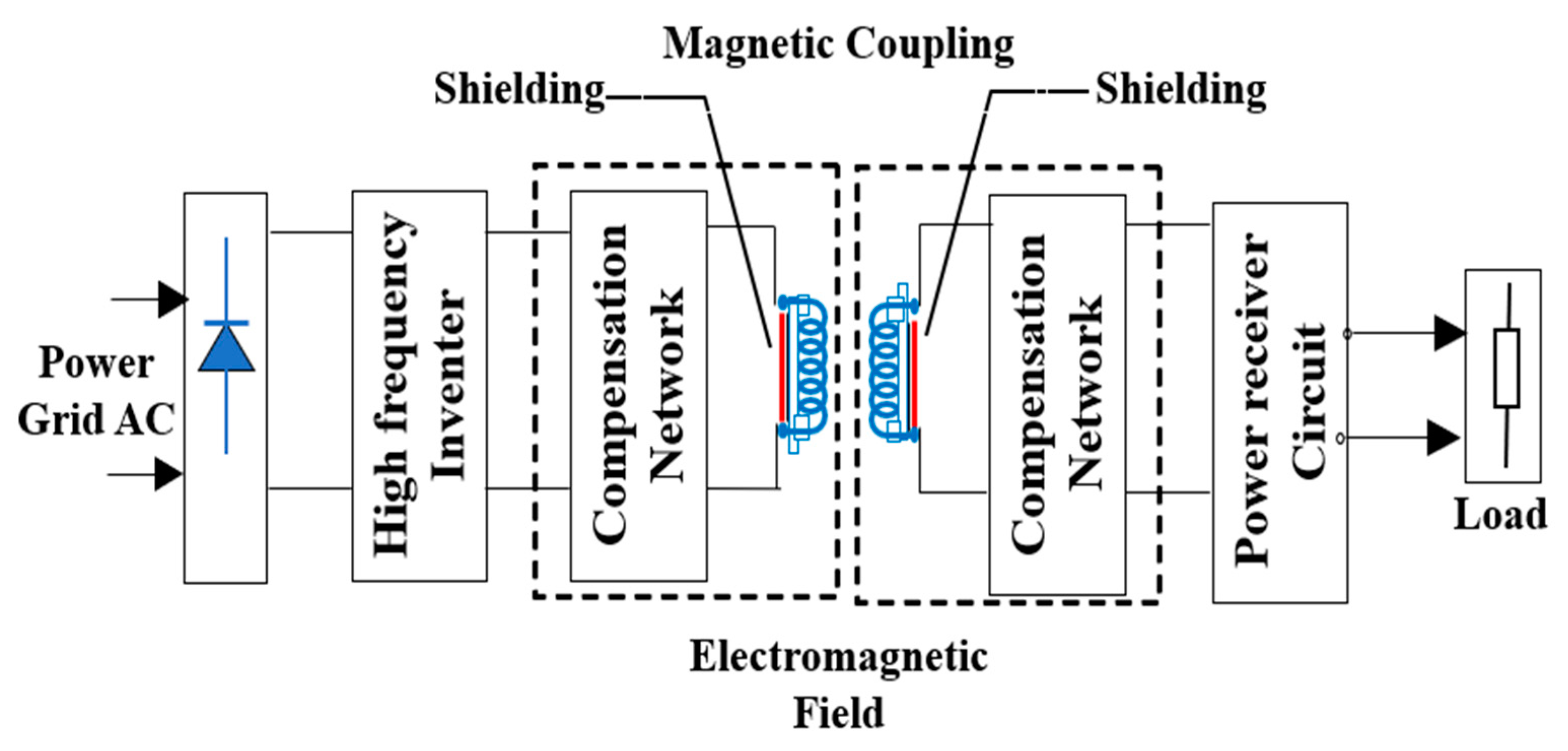
2. Description of WPT System

The system consists of two coils, one transmitting and the other receiving, which will serve as the transformer’s primary and secondary windings (Figure 1). The transmitting coil is supplied by an inverter which is connected to the grid through a rectifier. Once an alternating current is generated in the reception coil, a second rectifier is used to charge the battery [5].
The WPT system is represented by a single-phase transformer, shown by the equivalent circuit in Figure 2.
The governing system equations are expressed by [16]:
v 1 = L 1 d i 1 d t + M d i 2 d t + r 1 i 1
v 2 = L 2 d i 2 d t + M d i 1 d t r 2 i 2
The total radiated energy is expressed by:
W r a d = 1 2 L 1 i 1 2 + 1 2 L 2 i 2 2 + M i 1 i 2
where:
v1, v2; i1, i2; r1, r2; L1, L2 are respectively the voltages, currents, resistances and inductances of the primary and secondary coils.
M represents the mutual inductance between the primary and secondary coils.

3. Description of Spiral Coils in 3D

The transmitting and receiving coils have been modeled based on three-dimensional (3D) presentation using Ansys Maxwell software. The two copper coils with a plan spiral form are depicted in Figure 3. The distance between two adjacent wires in each coil, is taken equal to 50 mm. On the other hand, a rectangular plate is placed between the transmitter and the receiver coils in the main goal to ensure the capture of the magnetic field.
The simulations would take place fully in the air and would comprise 1000-square-millimeter areas. Figure 3 depicts the design of the rectangular spiral coils without ferrite core.
Table 1 includes information about the coil’s properties. Then, Table 2 and Table 3, respectively, provide information on the characteristics of the rectangular plate and the air region.

4. Analysis and Simulation Results

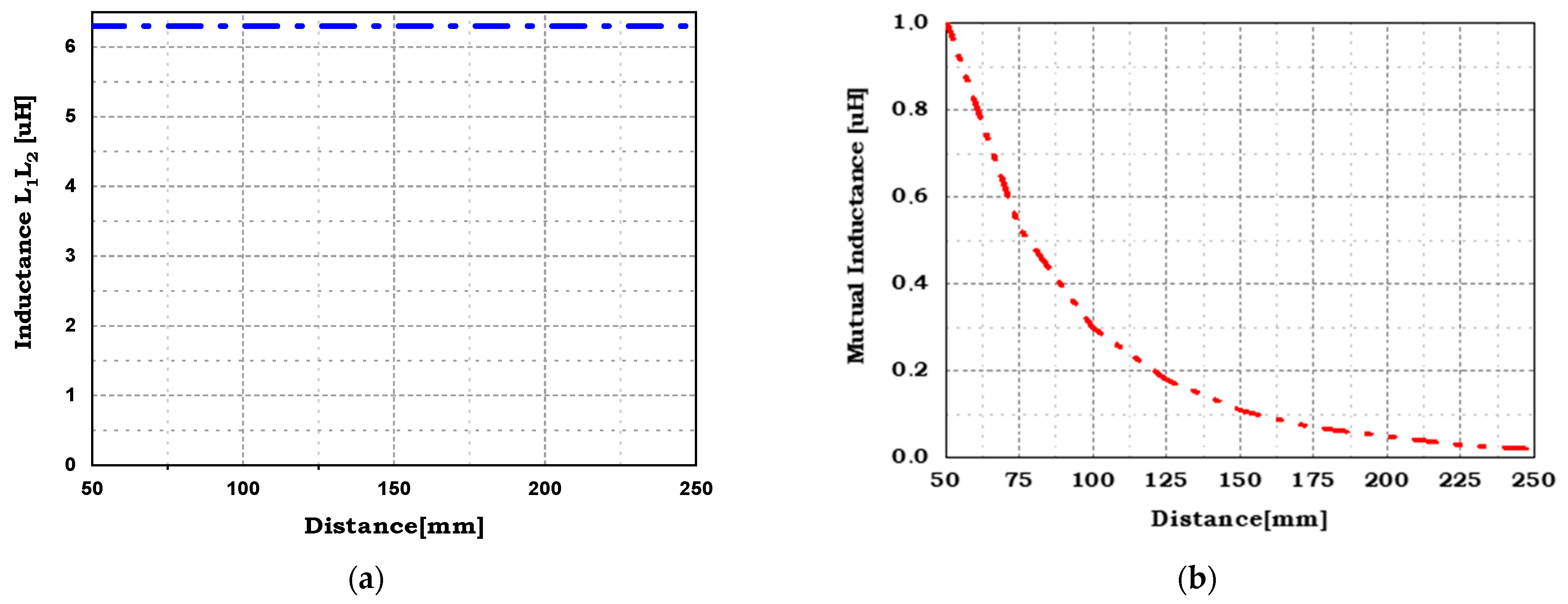
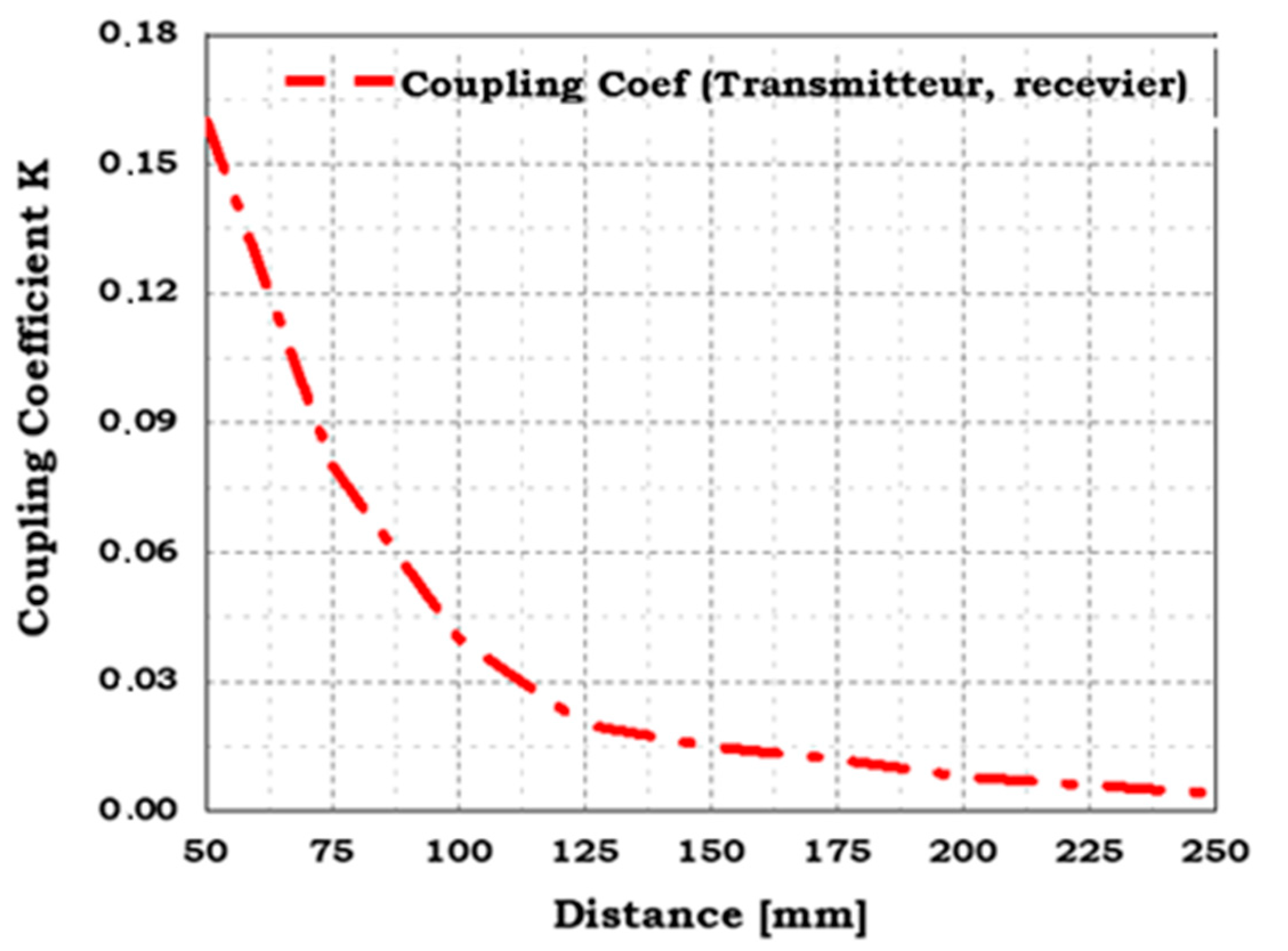
4.1. Case One: Coils in Air Gap

The authors in reference [16] limited their study to vertical misalignment. In this study, the two cases of vertical and horizontal misalignment are examined. The Ansys Maxwell tool is used to perform the 3D simulations and analysis of a spiral rectangular coil transformer. In the first step, according to Equation (3) the WPT model is examined without ferrite in order to provide the influence of the different electromagnetic parameters on the amount of energy transmitted as shown in Figure 4.

4.1.1. Vertical Misalignment (vd)

The calculation of the proper and mutual inductances is obtained by the variation of the vertical misalignment (vd) separating the two coils of the model. The magnetic permeability of the medium is that of air. As shown in Figure 5a, the self-inductances of the transmitting and receiving coils are constant despite variations in the vertical distance since the magnetic reluctance of each coil alone is unchanged. According to Figure 5b, the mutual inductance is inversely proportional to the distance between the two coils because the magnetic reluctance of the two coupled coils decreases.
Also, the radiated energy level can be estimated by the coupling coefficient. As can be seen in Figure 6, the coupling coefficient (K) varies in the same way as the mutual inductance as expressed by: K = M L 1 L 2 . Therefore, less radiated energy is obtained as the distance between the two coils increases.
Figure 7 shows that the field lines outside the region between the two coils are widespread. As a result, appropriate shielding is required.

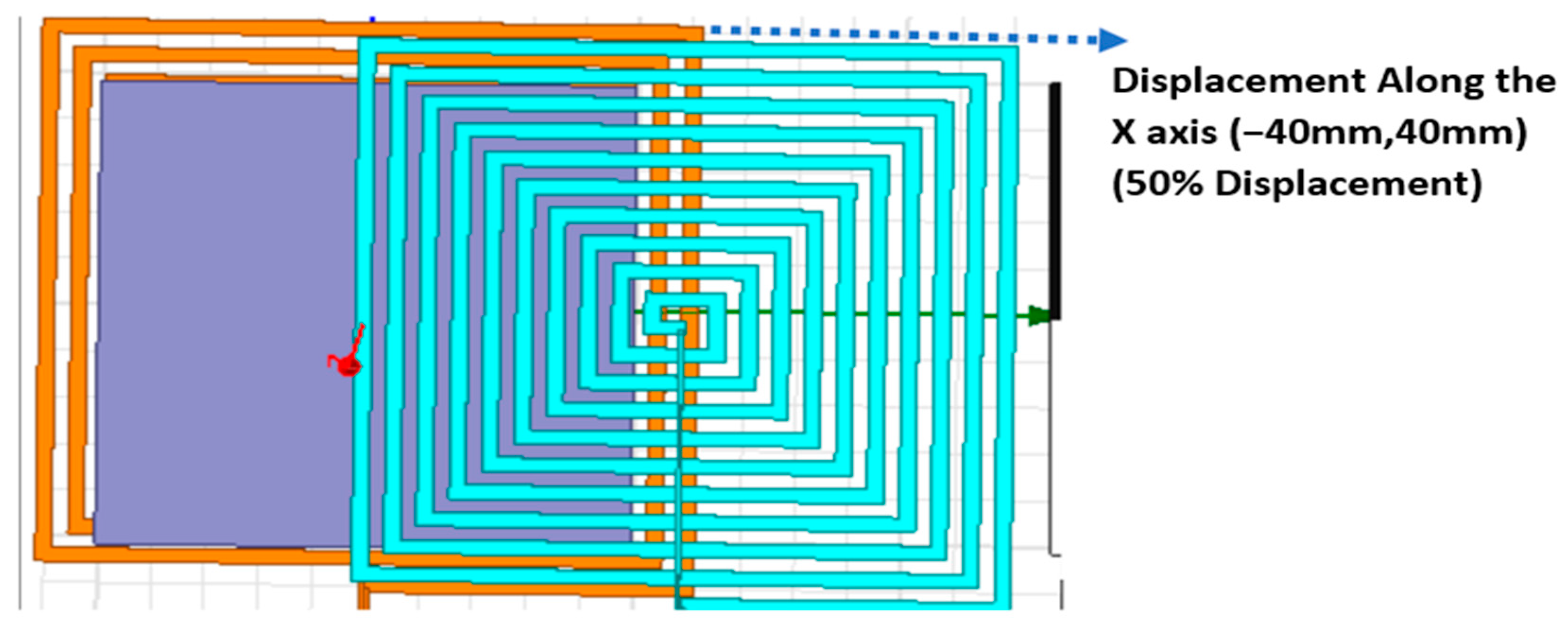
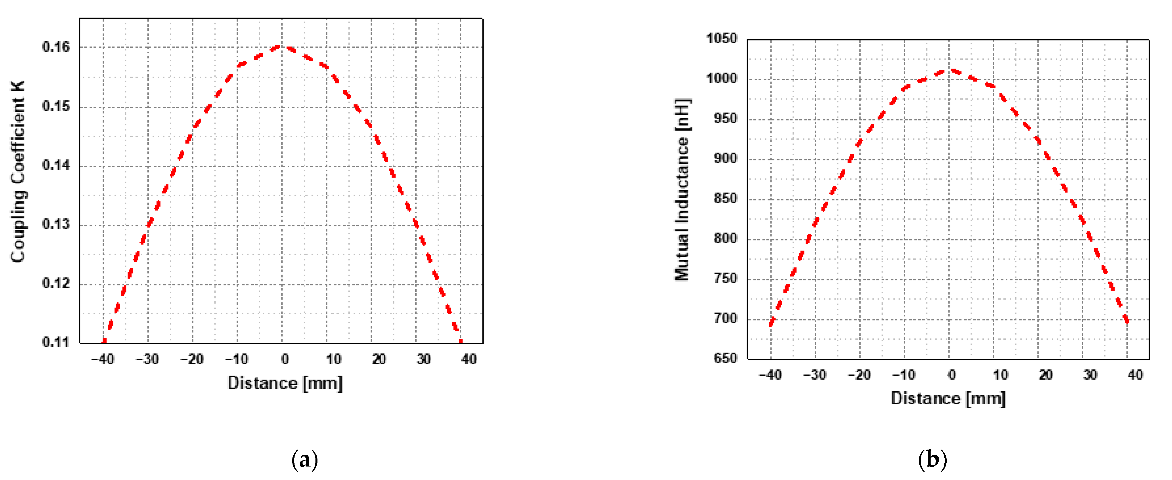
4.1.2. Horizontal Misalignment (hd)

This section examines the relationship between the coupling coefficient and the horizontal misalignment distances that range from −40 mm to 40 mm with a step of 10 mm as well as the relationship between the mutual inductance and the same distances as shown in Figure 8.
The obtained results show that the coupling coefficient and mutual induction vary in a parabolic-shaped forms. Both the mutual inductance and the coupling coefficient decrease as the misalignment is increased. When the misalignment is zero and the two coils are in phase (X = 0 mm), the coupling coefficient and mutual inductance also achieve their maximum values. As a result, the magnetic coefficients are more effective when the two coils are closely together, as shown in Table 4 and Table 5 and Figure 9.
From these results, it appears that in order to maintain a good level of radiated energy and the effectiveness of the power pad system, a series of transmitting coils must be installed along the path that the receiving coil follows.

4.2. Case Two: Ferrite on Coils (Simple Shielding)

The magnetic coupler leads to the channeling of the magnetic field lines in the energy transfer zone (between the two coils) and is designed to minimize their effect outside the coils. The position of the shielding is shown in Figure 10. In this figure, Lp and Ls are respectively the primary and secondary inductances and RL represents the charging battery.

4.3. Model of Single Shield Using Ferrite Core

Inserting the ferrite can enhance magnetic shielding and mutual inductance for a proper design of the magnetic coupler, particularly when there is a significant air gap as depicted in Figure 11. In this first part of the study, a magnetic coupler with and without ferrite cores is simulated using Ansys Maxwell.
The insertion of ferrite with higher relative magnetic permeability (μr ≈ 1000) improves the coupling coefficient and the energy transferred to the receiver coil especially for short gaps as shown in Figure 12.
The distribution of magnetic field lines is much more channeled in its propagation from the transmitting coil to the receiving coil. The simulated results show that the leakage flux remains important at the corners of the ferrite plate as depicted in Figure 13.
The insertion of the ferrite core has improved the shielding but the leakage flux still reduces the overall energy transfer. To overcome this drawback, a second shielding is introduced on top of the ferrite plate and the simulation results are described below.

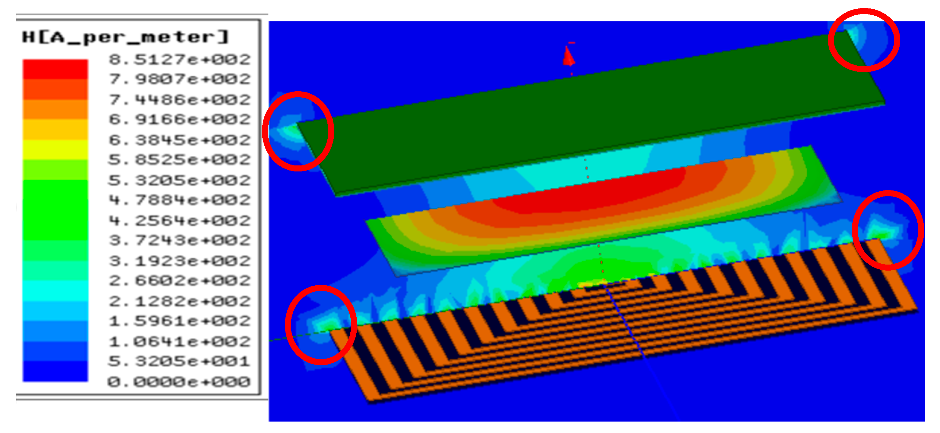
4.4. Case Three: Ferrite and Aluminum on Coils (Double Shielding)

The single shielding of the WPT model discussed above is improved in this second section by using a double shielding between the coils with Air gap of 50 mm where it is made by adding aluminum to the ferrite, realizing that the thickness of the Aluminum sheet is chosen as 1 mm as shown in Figure 14. The simulations are conducted using an eddy current solution with a frequency of 85 kHz with was undertaken with a starting frequency of 30 kHz and a stopping frequency of 85 kHz. Step Size 10 kHz and an alternating current.
The new self and mutual inductances are determined by varying the vertical distance (vd) between the two coils, as shown in Figure 15 and the results show that there is no effect of the double shielding on these parameters.
As shown in Figure 16, and indicated by red circles, the effect of adding a second shielding appears in reducing the leakage flux and thus improve the overall transfer of energy.

5. Conclusions

This article has dealt with the problem of energy transfer in WPT systems for electric vehicles. In order to optimize the power pad of the charging system, three cases of magnetic coupling between two identical rectangular spiral coils with the same number of turns depending on both the horizontal (X axis) and vertical (Z axis) alignment have been studied. In the first case where the magnetic circuit is air, the obtained results have shown that the primary and secondary self-inductances are constant and independent of the distance between the two coils. The distribution of the magnetic field has shown that the field lines are outside the area between the two coils which requires effective shielding. In the second case, a ferrite with a high magnetic permeability is inserted on top of the two coils so as to concentrate the field lines in the energy transfer area. As a result, the coupling coefficient was improved by 26%, as well as an increase in the level of transferred energy. This design improved the performance of the original system but the leakage flux still remains important. In the latter case, an additional insertion of an aluminum plate above the coils has been discussed. According to the results, aluminum effectively enhances the shielding. In perspective of the studies presented in this paper, the results can be validated and tested experimentally using different materials and shapes. Additionally, research should be done on the resonance phenomenon and the matrix of “emitting/receiving” coils in order to improve the effectiveness of the charging system.

Author Contributions

Conceptualization, N.B. and K.L.; methodology, N.B., K.L., I.B. and A.K.; software, N.B., K.L. and I.B.; validation, N.B., K.L., I.B. and A.K.; formal analysis, N.B., K.L., I.B. and A.K.; investigation, N.B., K.L., I.B., A.K., A.-D.B., R.K. and M.A.; resources, N.B., K.L., I.B. and A.K.; data curation, N.B., K.L., and I.B.; writing—original draft preparation, N.B., K.L., I.B. and A.K.; writing—review and editing, N.B., K.L., I.B., A.K., R.K. and M.A.; visualization, N.B., L.K, I.B. and A.K.; supervision, N.B., K.L., I.B., A.K., R.K. and M.A.; project administration, N.B., K.L., I.B., A.K., R.K. and M.A.; funding acquisition, R.K. and M.A. All authors have read and agreed to the published version of the manuscript.

Funding

This project was financially supported by the Directorate General for Scientific Research and Technological Development of the Algerian Ministry of Higher Education and Scientific Research in Algeria, the Laboratory of Applied automation and Industrial Diagnostics of Djelfa University, Algeria and the Laboratory LSPIE, University of Batna 2, Algeria.

Institutional Review Board Statement

Not applicable.

Informed Consent Statement

Not applicable.

Data Availability Statement

Not applicable.

Conflicts of Interest

The authors declare no conflict of interest.

References

  1. Brecher, A.; Arthur, D. Review and Evaluation of Wireless Power Transfer (WPT) for Electric Transit Applications; FTA Report No. 0060; Federal Transit Administration: Washington, DC, USA, 2014; pp. 1–61. [Google Scholar]
  2. Triviño-Cabrera, A.; González-González, J.M.; Aguado, J.A. Wireless Power Transfer for Electric Vehicles: Foundations and Design Approach; Springer: Cham, Switzerland, 2020. [Google Scholar] [CrossRef]
  3. Debbou, M.; Colet, F.; Kadem, K. Wireless inductive power transfer: Design and control for an optimal operation. In Proceedings of the 2018 20th European Conference on Power Electronics and Applications, Riga, Latvia, 17–21 September 2018; Volume 2018, pp. 1–8. [Google Scholar]
  4. Lassioui, A.; Fadil, H.E.; Belhaj, F.Z.; Rachid, A. Battery Charger for Electric Vehicles Based ICPT and CPT-A State of the Art. In Proceedings of the 2018 Renewable Energies, Power Systems Green Inclusive Economy (REPS-GIE), Casablanca, Morocco, 23–24 April 2018; pp. 1–6. [Google Scholar]
  5. Kim, J.; Kim, J.; Kong, S.; Kim, H.; Suh, I.-S.; Suh, N.P.; Cho, D.-H.; Kim, J.; Ahn, S. Coil Design and Shielding Methods for a Magnetic Resonant Wireless Power Transfer System. Proc. IEEE 2013, 101, 1332–1342. [Google Scholar] [CrossRef]
  6. Ongayo, D.; Hanif, M. Comparison of circular and rectangular coil transformer parameters for wireless Power Transfer based on Finite Element Analysis. In Proceedings of the 2015 IEEE 13th Brazilian Power Electronics Conference and 1st Southern Power Electronics Conference (COBEP/SPEC), Fortaleza, Brazil, 29 November–2 December 2015; pp. 1–6. [Google Scholar] [CrossRef]
  7. Mou, X.; Zhang, Y.; Jiang, J.; Sun, H. Achieving low carbon emission for dynamically charging electric vehicles through renewable energy integration. IEEE Access 2019, 7, 118876–118888. [Google Scholar] [CrossRef]
  8. Xiang, L.; Li, X.; Tian, J.; Tian, Y. A crossed DD geometry and its double-coil excitation method for electric vehicle dynamic wireless charging systems. IEEE Access 2018, 6, 45120–45128. [Google Scholar] [CrossRef]
  9. Mohammed, S.A.Q.; Jung, J.-W. A Comprehensive State-of-the-Art Review of Wired/Wireless Charging Technologies for Battery Electric Vehicles: Classification/Common Topologies/Future Research Issues. IEEE Access 2021, 9, 19572–19585. [Google Scholar] [CrossRef]
  10. Beretta, J. Report on User Centric EV Charging Infrastructure—INCIT-EV, 28 Sept, France. Available online: https://www.incit-ev.eu/report-on-user-centric-ev-charging-infrastructure/ (accessed on 15 September 2022).
  11. Cui, H.; Zhong, W.; Li, H.; He, F.; Chen, M.; Xu, D. A study on the shielding for wireless charging systems of electric vehicles. In Proceedings of the 2018 IEEE Applied Power Electronics Conference and Exposition (APEC), San Antonio, TX, USA, 4–8 March 2018; pp. 1336–1343. [Google Scholar]
  12. Campi, T.; Cruciani, S.; Feliziani, M.; Maradei, F. Magnetic field generated by a 22 kW–85 kHz wireless power transfer system for an EV. In Proceedings of the 2017 AEIT International Annual Conference, Cagliari, Italy, 20–22 September 2017. [Google Scholar]
  13. Wang, Q.; Li, W.; Kang, J.; Wang, Y. Electromagnetic safety of magnetic resonant wireless charging system in electric vehicles. In Proceedings of the 2017 IEEE PELS Workshop on Emerging Technologies: Wireless Power Transfer (WoW), Chongqing, China, 20–22 May 2017. [Google Scholar]
  14. Wang, Q.; Li, W.; Kang, J.; Wang, Y. Magnetic Field Distribution in a WPT System for Electric Vehicle Charging. In Proceedings of the Progress in Electromagnetic Research Symposium (PIERS), Shanghai, China, 8 August–11 September 2016; p. 5165. [Google Scholar]
  15. Sibakoti, M.J.; Hambleton, J. Wireless Power Transmission Using Magnetic Resonance; Cornell College PHY312: Mount Vernon, IA, USA, 2011. [Google Scholar]
  16. El-Shahat, A.; Ayisire, E. Novel Electrical Modeling, Designand Comparative Control Techniques for Wireless Electric Vehicle Battery Charging. Electronics 2021, 10, 2842. [Google Scholar] [CrossRef]
  17. De Santis, V.; Giaccone, L.; Freschi, F. Chassis Influence on the Exposure Assessment of a Compact EV during WPT Recharging Operations. Magnetochemistry 2021, 7, 25. [Google Scholar] [CrossRef]
  18. De Santis, V.; Giaccone, L.; Freschi, F. Influence of Posture and Coil Position on the Safety of a WPT System While Recharging a Compact EV. Energies 2021, 14, 7248. [Google Scholar] [CrossRef]
  19. Li, Y.; Zhang, S.; Cheng, Z. Double-Coil Dynamic Shielding Technology for Wireless Power Transmission in Electric Vehicles. Energies 2021, 14, 5271. [Google Scholar] [CrossRef]
  20. Xu, H.; Wang, C.; Xia, D.; Liu, Y. Design of Magnetic Coupler for Wireless Power Transfer. Energies 2019, 12, 3000. [Google Scholar] [CrossRef] [Green Version]
  21. International SAE J2954. Wireless Power Transfer for Light-Duty Plug-In/Electric Vehicles and Alignment Methodology; SAE International: Warrendale PA, USA, 2019. [Google Scholar]
  22. IEEE C95.1-2019. IEEE Standard for Safety Levels with Respect to Human Exposure to Electric, Magnetic, and Electromagnetic Fields, 0 Hz to 300 GHz; IEEE Press: Piscataway, NJ, USA, 2019. [Google Scholar]
  23. ICNIRP. Guidelines for Limiting Exposure to Time-Varying Electric and Magnetic Fields (1 Hz–100 kHz). Health Phys. 2010, 99, 818–836. [Google Scholar] [CrossRef] [PubMed]
  24. Park, S.W.; Wake, K.; Watanabe, S. Incident electric field effect and numerical dosimetry for a wireless power transfer system using magnetically coupled resonances. IEEE Trans. Microw. Theory Tech. 2013, 61, 3461–3469. [Google Scholar] [CrossRef]
  25. De Santis, V.; Campi, T.; Cruciani, S.; Laakso, I.; Feliziani, M. Assessment of the Induced Electric Fields in a Carbon-FiberElectrical Vehicle Equipped with a Wireless Power Transfer System. Energies 2018, 11, 684. [Google Scholar] [CrossRef] [Green Version]
  26. Arduino, A.; Bottauscio, O.; Chiampi, M.; Giaccone, L.; Liorni, I.; Kuster, N.; Zilberti, L.; Zucca, M. Accuracy Assessment of Numerical Dosimetry for the Evaluation of Human Exposure to Electric Vehicle Inductive Charging Systems. IEEE Trans. Electromag. Compat. 2020, 62, 1939–1950. [Google Scholar] [CrossRef]
  27. Kadem, K.; Bensetti, M.; LeBihan, Y.; Labouré, E.; Debbou, M. Optimal Coupler Topology for Dynamic Wireless Power Transfer for Electric Vehicle. Energies 2021, 14, 3983. [Google Scholar] [CrossRef]
  28. Mohameda, A.A.S.; Shaiera, A.A.; Metwallya, H.; Sameh, I.; Selem, S. A comprehensive overview of inductive pad in electric vehicles. Appl. Energy 2020, 262, 114584. [Google Scholar] [CrossRef]
  29. Yang, Y.; Cui, J.; Cui, X. Design and Analysis of Magnetic CoilsforOptimizingthe Coupling CoeffcientinanElectricVehicleWireless Power Transfer System. Energies 2020, 13, 4143. [Google Scholar] [CrossRef]
  30. Ahmad, A.; Alam, M.S.; Chabaan, R.; Mohamed, A. Comparative Analysis of Power Pad for Wireless Charging of Electric Vehicles; SAE Technical Paper 2019-01-0865; SAE: Sydney, Australia, 2019. [Google Scholar] [CrossRef]
  31. Benalia, N.; Kouider, L.; Benlaloui, I. Improvement of the Magnetic Coupler design for Wireless Inductive Power Transfer. In Proceedings of the 5th International Conference on Power Electronics and Their Applications ICPEA, Hail, Saudi Arabia, 29–31 March 2022. [Google Scholar] [CrossRef]
  32. Budhia, M.; Covic, G.A.; Boys, J.T. Design and Optimization of Circular Magnetic Structures for Lumped Inductive Power Transfer Systems. IEEE Trans. Power Electron. 2011, 26, 3096–3108. [Google Scholar] [CrossRef]
  33. Dolara, A.; Leva, M.S.; Longo, F.; Castelli-Dezza, M.M. Coil design and magnetic shielding of a resonant wireless power transfer system for electric vehicle battery charging. In Proceedings of the 2017 IEEE 6th International Conference on Renewable Energy Research and Applications (ICRERA), San Diego, CA, USA, 5–8 November 2017; pp. 200–205. [Google Scholar]
  34. Xu, D.; Zhang, Q.; Li, X. Implantable Magnetic Resonance Wireless Power Transfer System Based on 3D Flexible Coils. Sustainability 2020, 12, 4149. [Google Scholar] [CrossRef]
  35. Budhia, M.; Covic, G.; Boys, J. A New IPT Magnetic Coupler for Electric Vehicle Charging Systems. In Proceedings of the IECON 2010—36th Annual Conference on IEEE Industrial Electronics Society, Glendale, AZ, USA, 7–10 November 2010; pp. 2487–2492. [Google Scholar]
  36. Gao, Y.; Ginart, A.; Farley, K.B.; Tse, Z.T.H. Misalignment Effect on Efficiency of Wireless Power Transfer for Electric Vehicles. In Proceedings of the 2016 IEEE Applied Power Electronics Conference and Exposition (APEC), Long Beach, CA, USA, 20–24 March 2016; Volume 16, p. 24. [Google Scholar]
  37. Caillierez, A. Study and Implementation of the Transfer of Electrical Energy by Induction: Application to the Electric Road for Moving Vehicles. Master’s Thesis, University Paris-Saclay, Orsay, France, 2016. [Google Scholar]
  38. Razu, R.R.; Mahmud, S.; Uddin, M.J.; Islam, S.S.; Bais, B.; Misran, N.; Islam, M.T. Wireless Charging of Electric Vehicle While Driving. IEEE Access 2021, 9, 157973–157983. [Google Scholar] [CrossRef]
Figure 1. Typical WPT charging system for Evs.
Sustainability 15 01230 g001
Figure 2. The magnetic circular coupler and its analogous circuit.
Sustainability 15 01230 g002
Figure 3. Design of the rectangular spiral coils without ferrite.
Sustainability 15 01230 g003
Figure 4. Design of the rectangular spiral coils without ferrite.
Sustainability 15 01230 g004
Figure 5. (a) Self-inductances and (b) Mutual inductance, under variation of vertical misalignment d = 50 mm up to 250 mm, of the rectangular spiral coils without ferrite.
Sustainability 15 01230 g005
Figure 6. Coupling coefficient under variation of vertical d = 50 mm up to 250 mm, of two identical rectangular spiral coils without ferrite.
Sustainability 15 01230 g006
Figure 7. Distribution of magnetic field (H) lines for d = 50 mm.
Sustainability 15 01230 g007
Figure 8. Displacement with misalignment along the X axis.
Sustainability 15 01230 g008
Figure 9. Variation of: (a) coupling coefficient and (b) mutual inductance with horizontal misalignment hd = −40 mm up to 40 mm.
Sustainability 15 01230 g009
Figure 10. The inductive coupled (WPT) system.
Sustainability 15 01230 g010
Figure 11. Magnetic coupler with a single shielding.
Sustainability 15 01230 g011
Figure 12. Variations of the mutual inductance with and without ferrite along the misalignment distance.
Sustainability 15 01230 g012
Figure 13. Magnetic field (H) along the ZY axis with ferrite at vd = 50 mm.
Sustainability 15 01230 g013
Figure 14. Magnetic coupler with a double shielding.
Sustainability 15 01230 g014
Figure 15. (a) Mutual inductance;(b) coupling coefficient, with ferrite and a variation of d = 50 mm up to 250 mm.
Sustainability 15 01230 g015
Figure 16. Magnetic field (H) along the ZY axis with ferrite and aluminum (d = 50 mm).
Sustainability 15 01230 g016
Table 1. The coil’s properties.
NameTransmitter CoilReceiver Coil
Number of turns1010
Width of the spiral coil3 mm3 mm
Thickness of the spiral coil0.0762 mm0.0762 mm
Distance between turns6 mm6 mm
Frequency 85 kHz
Apparent Power33.6 KVA
Active Power14.8 KW
Table 2. Rectangular plate properties.
CommandCoordinate SystemPositionAxisY SizeZ Size
Rectangleglobal50, 0.70Z−70 mm−70 mm
Table 3. The air region properties.
NameValueUnitEvaluated Value
CommandCreated box
Coordinate systemGlobal
Position−500, −500, −500mm−500, −500, −500
Xsize1000mm1000
Ysize1000mm1000
Wsize1000mm1000
Table 4. Inductor values obtained from horizontal misalignment.
Z Space [mm]Mutual Inductance [nH]
1−40692.976
2−30819.490
3−20922.116
4−10989.814
501013.691
610991.027
720924.681
830822.780
940696.879
Table 5. Coupling coefficient values obtained from horizontal misalignment.
Z Space [mm]Coupling Coefficient
1−400.109618
2−300.129554
3−200.145936
4−100.156849
500.160521
6100.156756
7200.146528
8300.130157
9400.110225
Disclaimer/Publisher’s Note: The statements, opinions and data contained in all publications are solely those of the individual author(s) and contributor(s) and not of MDPI and/or the editor(s). MDPI and/or the editor(s) disclaim responsibility for any injury to people or property resulting from any ideas, methods, instructions or products referred to in the content.

