
Numerical Simulation of Corrugated Steel Concrete Prefabricated Support Structure for Underground Engineering

Abstract
:1. Introduction
2. Structural Design
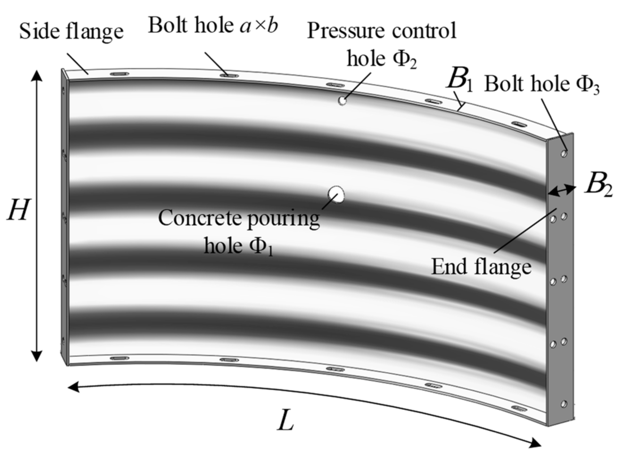
2.1. Main Structure
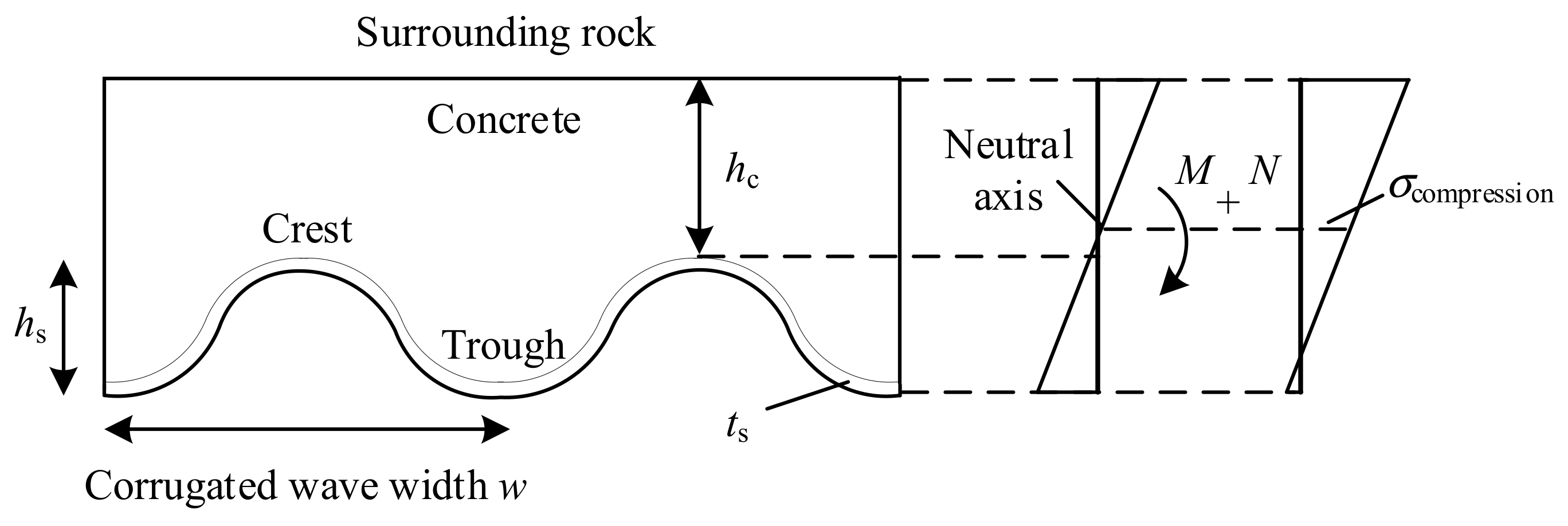
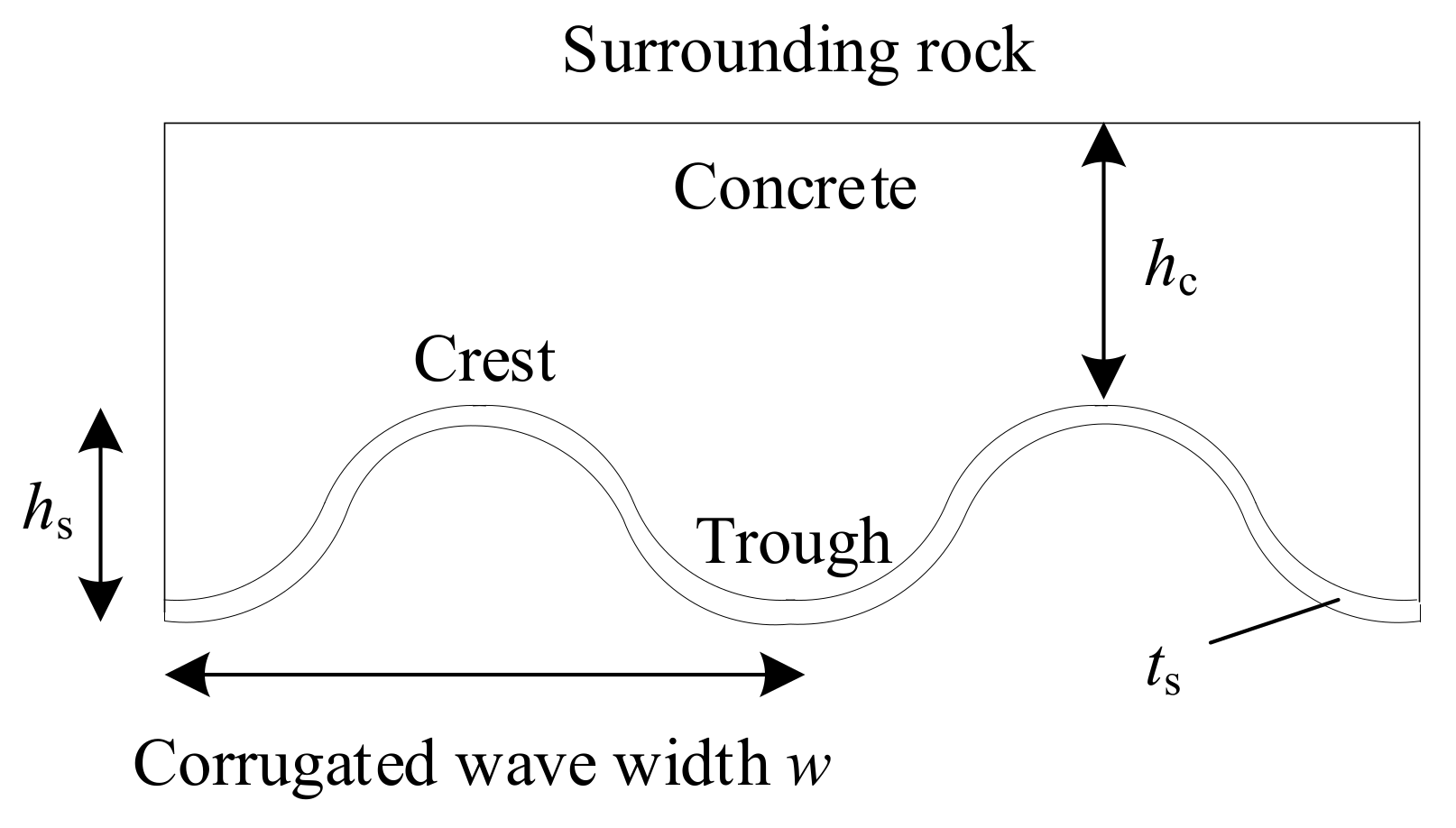
2.2. Corrugated Steel Plate
2.3. Structural Characteristics
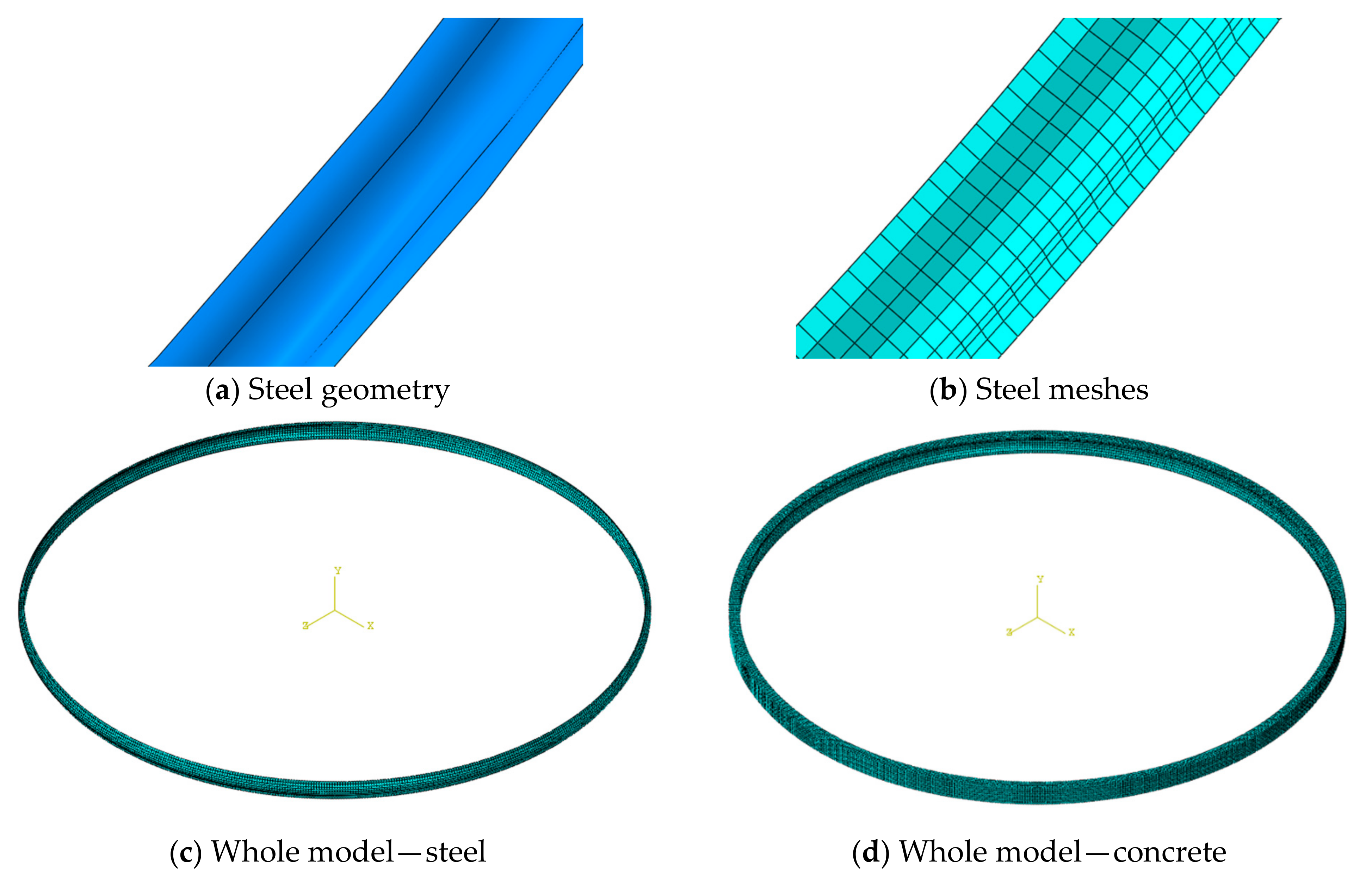
3. Numerical Modeling
3.1. General Setting
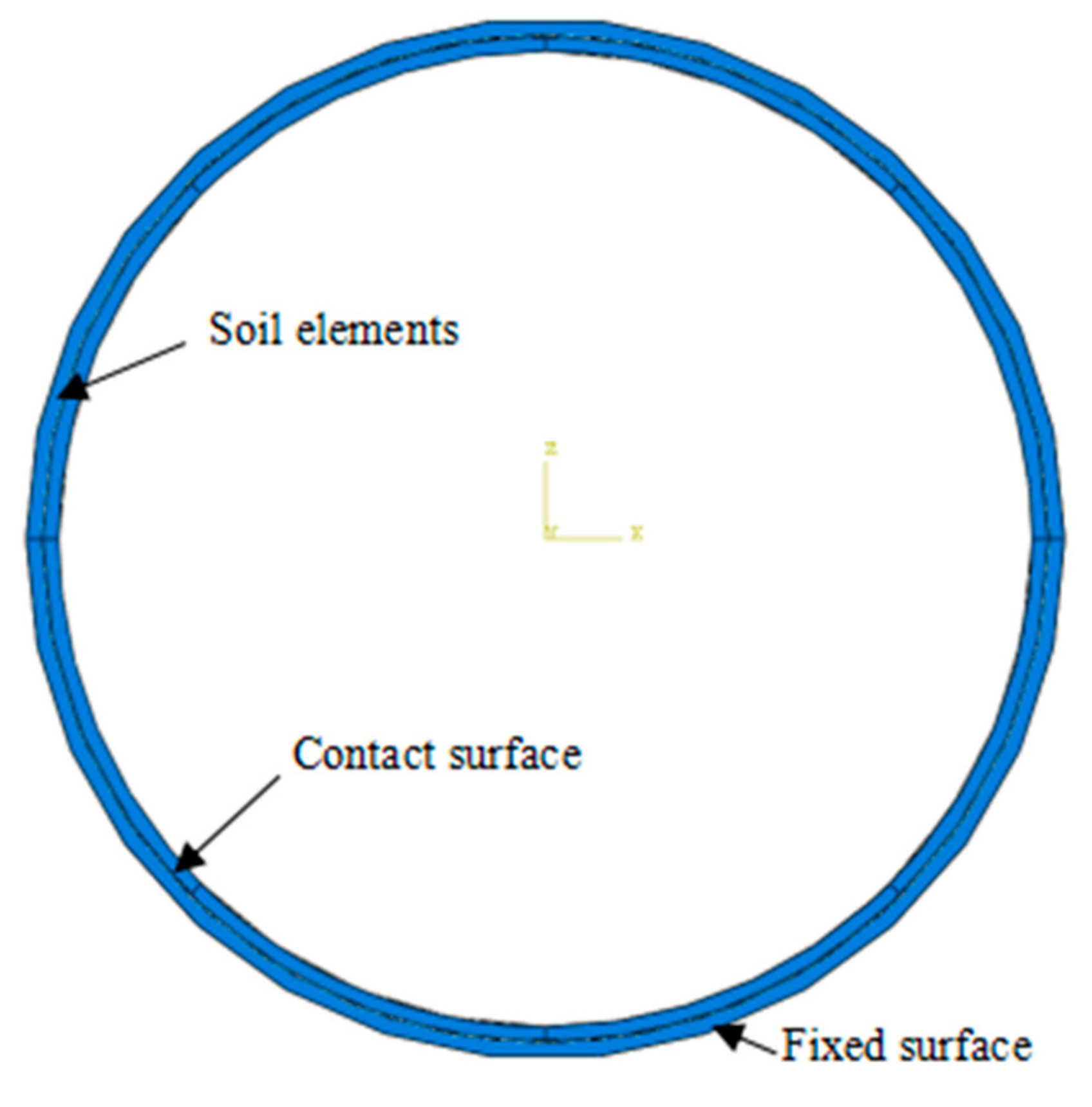
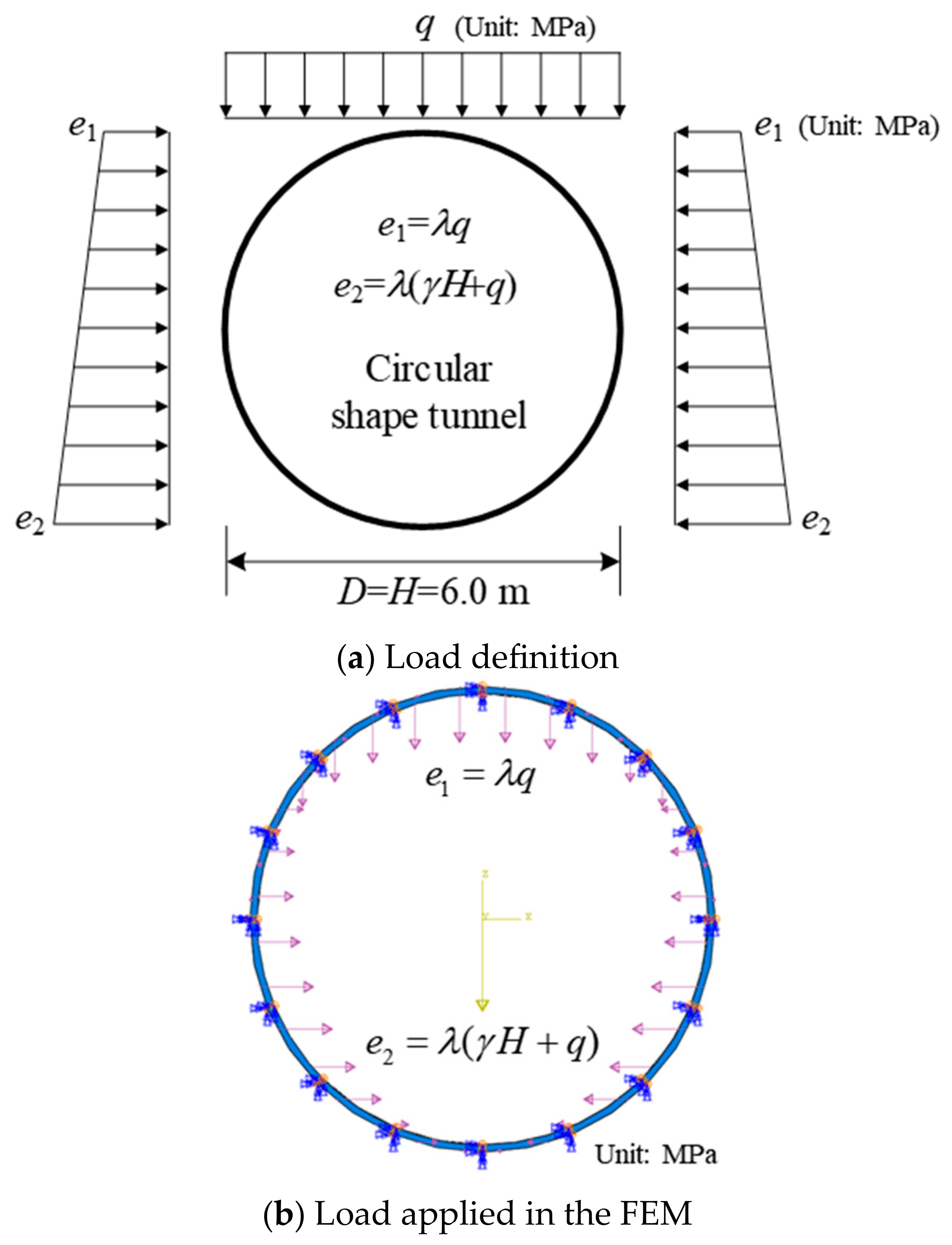
3.2. Boundary Conditions and Loads
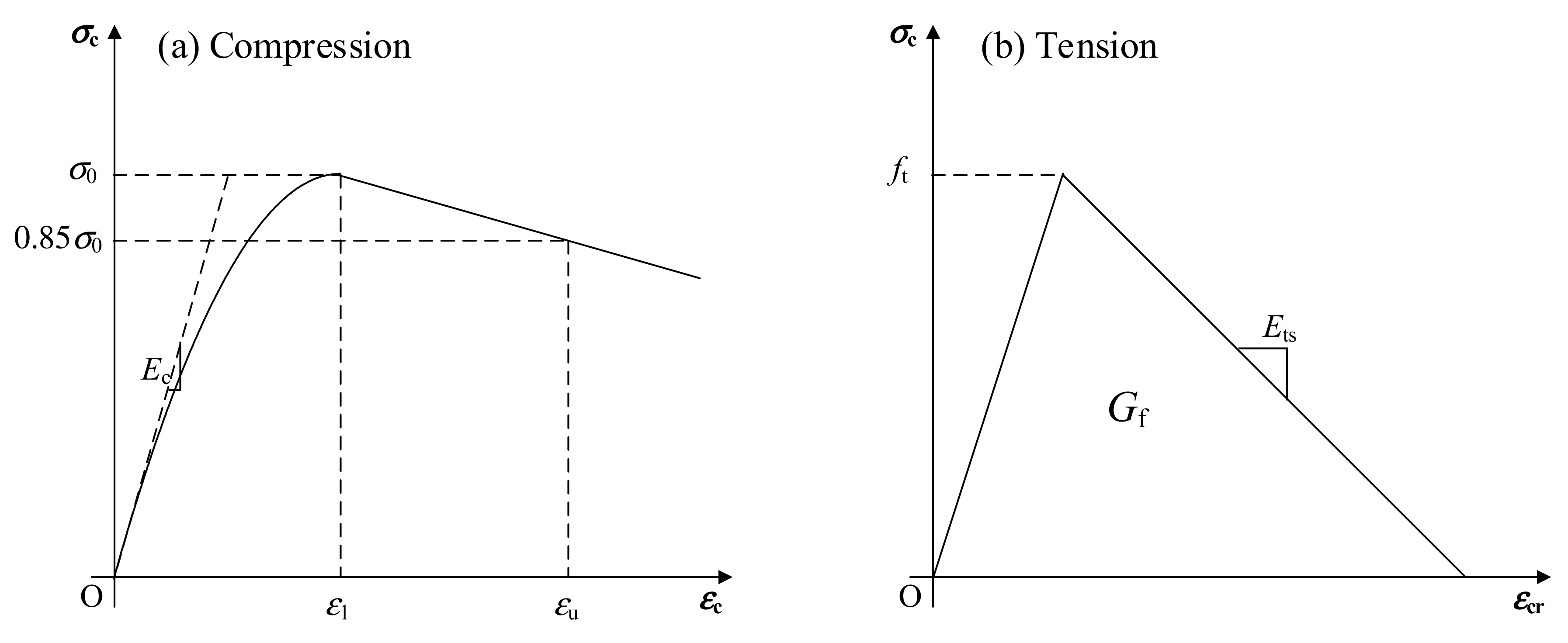
3.3. Materials
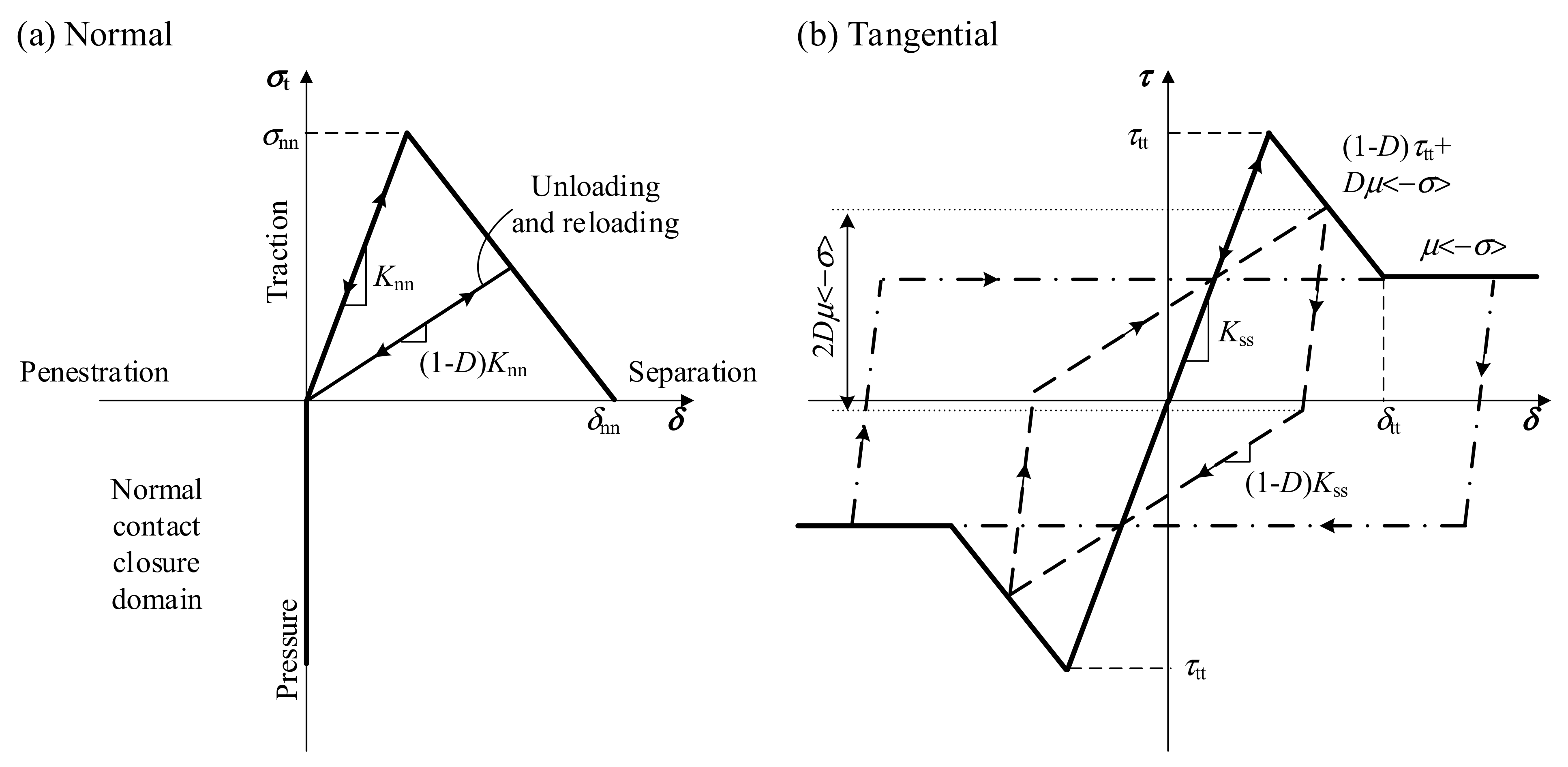
3.4. Interfaces
4. Results and Discussion
4.1. Influence of Interfacial Bond
4.2. Ultimate Response
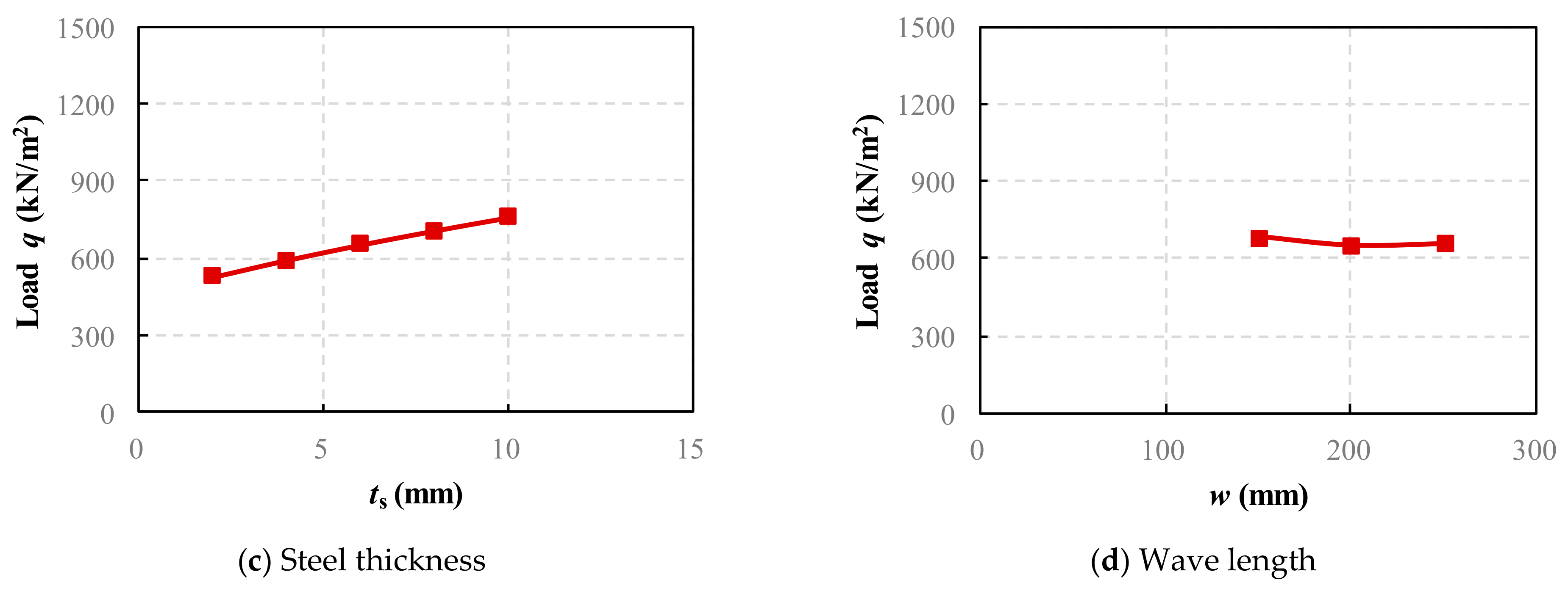
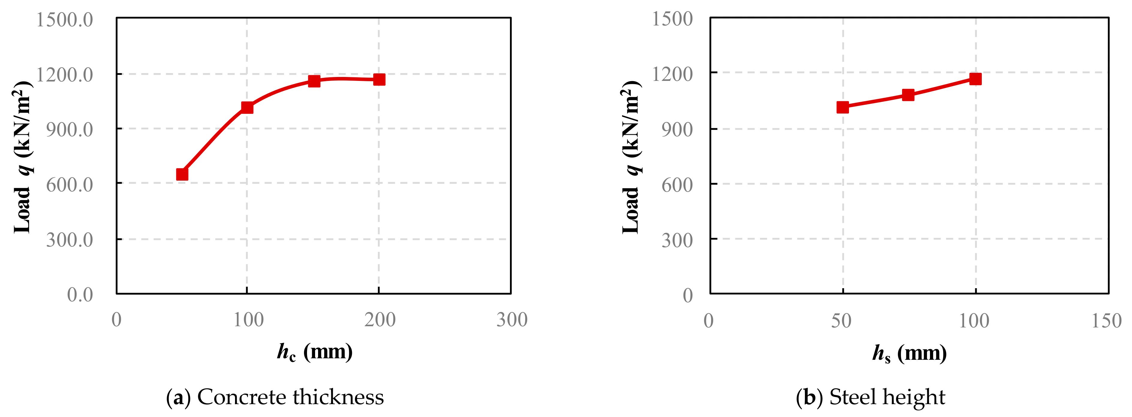
5. Parametric Studies
6. Design Considerations
7. Conclusions
- (1)
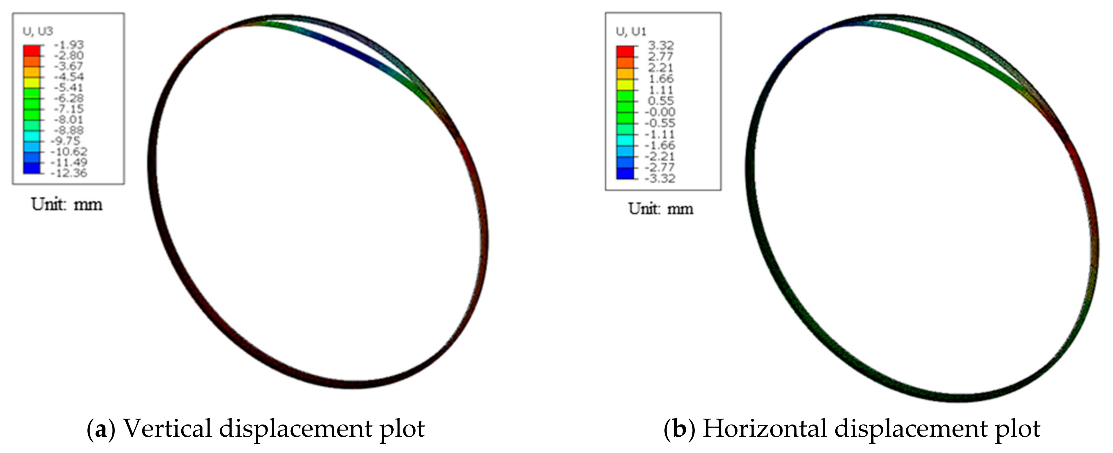
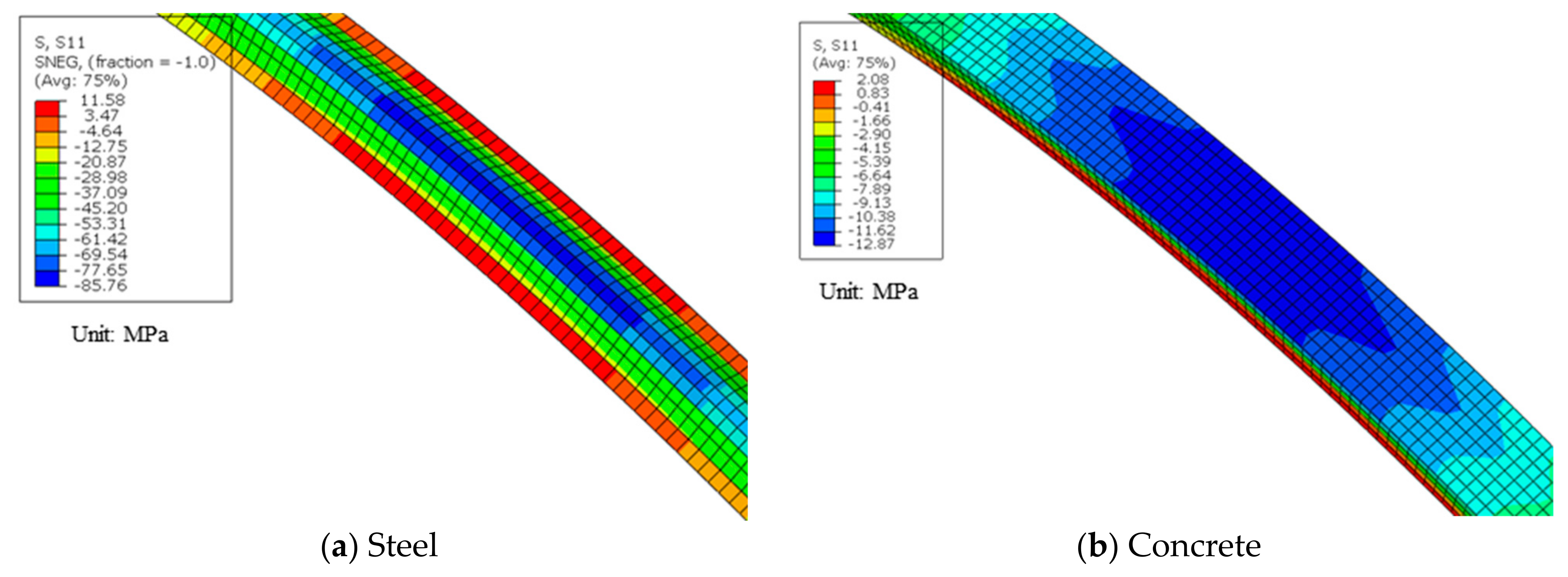
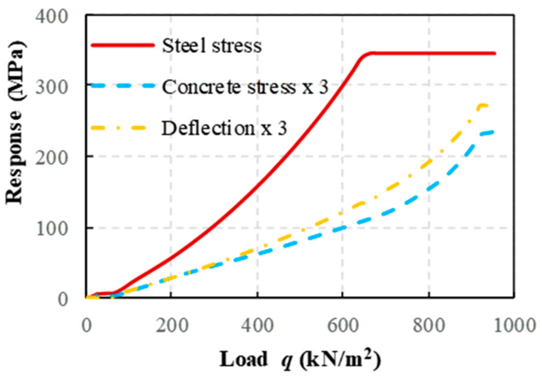
- An innovative CSC composite structure employed in tunnel support was proposed, accompanied by detailed construction methods. The novel composite structure has high stability performance compared to previous steel structures, since the concrete can provide out-of-plane support. Precise elastoplastic finite element models were developed to assess the mechanical response until the failure of the proposed system. These models additionally account for the steel–concrete interfacial properties and contact interactions. Non-uniform loads were analytically applied based on field methods, with foundation interactions computed through frictionless elements. Under typical loading conditions, cohesive stress and frictional forces provided adequate connections such that the structure behaved in a nearly fully composite way. The predominant failure modes were steel yield and concrete crushing in the middle top area.
- (2)
- Parametric analyses spanning common design ranges were conducted, revealing that the thickness of the concrete, thickness of the steel, and height of the corrugated plate were key factors affecting the structural response. Designers ought to avoid excessively thick concrete, which could lead to brittle concrete crushing failure.
- (3)
- Theoretical analyses were conducted based on numerical studies, from which design equations and recommendations were developed. These demonstrated high efficacy and accuracy for most engineering applications.
Author Contributions
Funding
Institutional Review Board Statement
Informed Consent Statement
Data Availability Statement
Conflicts of Interest
References
- National Research Council. Underground Engineering for Sustainable Urban Development; National Academies Press: Washington, DC, USA, 2013. [Google Scholar]
- Curiel-Esparza, J.; Canto-Perello, J.; Calvo, M.A. Establishing sustainable strategies in urban underground engineering. Sci. Eng. Ethics 2004, 10, 523–530. [Google Scholar] [CrossRef] [PubMed]
- Galan, I.; Baldermann, A.; Kusterle, W.; Dietzel, M.; Mittermayr, F. Durability of shotcrete for underground support–Review and update. Constr. Build. Mater. 2019, 202, 465–493. [Google Scholar] [CrossRef]
- Guler, S.; Öker, B.; Akbulut, Z.F. Workability, strength and toughness properties of different types of fiber-reinforced wet-mix shotcrete. Structures 2021, 31, 781–791. [Google Scholar] [CrossRef]
- Liu, G.; Zhao, J.; Zhang, Z.; Wang, C.; Xu, Q. Mechanical properties and microstructure of shotcrete under high temperature. Appl. Sci. 2021, 11, 9043. [Google Scholar] [CrossRef]
- Kaufmann, J.; Loser, R.; Winnefeld, F.; Leemann, A. Sulfate resistance and phase composition of shotcrete. Tunn. Undergr. Sp. Tech. 2021, 109, 103760. [Google Scholar] [CrossRef]
- Yelemessov, K.; Sabirova, L.B.; Martyushev, N.V.; Malozyomov, B.V.; Bakhmagambetova, G.B.; Atanova, O.V. Modeling and Model Verification of the Stress-Strain State of Reinforced Polymer Concrete. Materials 2023, 16, 9. [Google Scholar] [CrossRef] [PubMed]
- Siddique, R.; Naik, T.R. Properties of concrete containing scrap-tire rubber—An overview. Waste Manag. 2004, 24, 563–569. [Google Scholar] [CrossRef] [PubMed]
- Chen, T.; Su, M.; Pan, C.; Zhang, L.; Wang, H. Local buckling of corrugated steel plates in buried structures. Thin-Walled Struct. 2019, 144, 106348. [Google Scholar] [CrossRef]
- Zhang, W.; Mahdavian, M.; Yu, C. Lateral strength deflection of cold-formed steel shear walls using corrugated sheathing. J. Constr. Steel Res. 2018, 148, 399–408. [Google Scholar] [CrossRef]
- Zhang, M.; Han, Y.; Li, P.; Guo, C. Field experimental study on steel-corrugated plate-mold bag concrete supporting structure of circular shaft. Tunn. Constr. 2022, 42, 1146–1155. [Google Scholar]
- Chen, X. Numerical Simulation and Design Scheme of Assembled Type Corrugated Steel Plate Lining for Subway Tunnel; Beijing University of Technology: Beijing, China, 2017. [Google Scholar]
- Chen, W.; Liu, B.; Liu, R. Analysis of Working Effect of Corrugated Steel Lining on Tunnel Lining Fall. Tunn. Constr. 2018, 12, 384. [Google Scholar]
- Takashi, H. Corrugate Fiber Reinforced Plastic Sheet in Repairing Tunnel Linings. J. Civil Eng. Architect. 2015, 9, 684–690. [Google Scholar] [CrossRef]
- Korusiewicz, L.; Kunecki, B. Behaviour of the steel box-type culvert during backfilling. Arch. Civ. Mech. Eng. 2011, 11, 637–650. [Google Scholar] [CrossRef]
- García, D.B.; Moore, I.D. Behavior of coupling band joints in buried corrugated steel pipelines. J. Geotech. Geoenviron. 2014, 140, 04013014. [Google Scholar] [CrossRef]
- Sezen, H.; Yeau, K.Y.; Fox, P.J. In-situ load testing of corrugated steel pipe-arch culverts. J. Perform. Constr. Fac. 2008, 22, 245–252. [Google Scholar] [CrossRef]
- Beben, D. Dynamic amplification factors of corrugated steel plate culverts. Eng. Struct. 2013, 46, 193–204. [Google Scholar] [CrossRef]
- Li, Y.; Xu, J.; Nan, F.; Su, H.; Zhao, T. Dynamic Simulation and Experimental Study of the HDPE Double-Walled Corrugated Pipe Grouting Robot. Sustainability 2022, 14, 6776. [Google Scholar] [CrossRef]
- Sun, K.; Hong, Y.; Xu, W.; Hou, Z.; Liu, X.; Yu, M.; Yuan, Z. Analysis and prediction of mechanical characteristics of corru-gated plate as primary support in tunnels. Tunn. Undergr. Sp. Tech. 2021, 111, 103845. [Google Scholar] [CrossRef]
- Sun, K.; Hong, Y.; Xu, W.; Liu, H.; Zhen, Y.; Qin, J. Analysis and prediction of the mechanical behavior of corrugated plate as primary support in tunnels with elastoplastic constitution. Tunn. Undergr. Sp. Tech. 2022, 124, 104451. [Google Scholar] [CrossRef]
- Kunecki, B.; Korusiewicz, L. Field Test of Soil-Steel Arch with Ribs and Calculation of Internal Forces on the Basis of Measured Strains; Research and Applications in Structural Engineering, Mechanics and Computation; CRC Press: Boca Raton, FL, USA, 2013; pp. 933–934. [Google Scholar]
- Hatami, H.; Shariati, M. Numerical and experimental investigation of SS304L cylindrical shell with cutout under uniaxial cyclic loading. Iran. J. Sci. Technol. Trans. Mech. Eng. 2019, 43, 139–153. [Google Scholar] [CrossRef]
- Zhang, L.; Hebert, R.; Wright, J.T.; Shukla, A.; Kim, J.H. Dynamic response of corrugated sandwich steel plates with grad-ed cores. Int. J. Impact. Eng. 2014, 65, 185–194. [Google Scholar] [CrossRef]
- Zamanifar, H.; Sarrami-Foroushani, S.; Azhari, M. Static and dynamic analysis of corrugated-core sandwich plates using finite strip method. Eng. Struct. 2019, 183, 30–51. [Google Scholar] [CrossRef]
- Guo, Y.T.; Nie, X.; Tao, M.X.; Ding, R.; Tang, L.; Fan, J.S. Selected series method on buckling design of stiffened steel-concrete composite plates. J. Constr. Steel Res. 2019, 161, 296–308. [Google Scholar] [CrossRef]
- Sokolinsky, V.S.; Indermuehle, K.C.; Hurtado, J.A. Numerical simulation of the crushing process of a corrugated composite plate. Compos. Part A Appl. Sci. Manuf. 2011, 42, 1119–1126. [Google Scholar] [CrossRef]
- Cheng, Z.; Zhang, Q.; Bao, Y.; Deng, P.; Wei, C.; Li, M. Flexural behavior of corrugated steel-UHPC composite bridge decks. Eng. Struct. 2021, 246, 113066. [Google Scholar] [CrossRef]
- Guo, Y.T.; Yang, Y.; Song, S.Y.; Fan, J.S. Shear–slip failure in steel–concrete–steel composite beams with bidirectional webs. Thin-Walled Struct. 2021, 164, 107743. [Google Scholar] [CrossRef]
- Song, S.; Guo, Y.; Fan, J.; Elghazouli, A.Y. Shear Contribution of Flange Dowel Action in Steel-Concrete-Steel Composite Structures. Thin-Walled Struct. 2021, 169, 108354. [Google Scholar] [CrossRef]
- Guo, Y.T.; Nie, X.; Fan, J.S.; Tao, M.X. Shear resistance of steel–concrete–steel deep beams with bidirectional webs. Steel Compos. Struct. 2022, 42, 299–313. [Google Scholar]
- Abbas, H.S.; Bakar, S.A.; Ahmadi, M.; Haron, Z. Experimental studies on corrugated steel-concrete composite slab. Gradevinar 2015, 67, 225–233. [Google Scholar] [CrossRef]
- Zhang, J.; Liu, B.; Liu, R. Behavior of sinusoidal-corrugated-steel-plate–concrete composite slabs: Experimental investigation theoretical model development. J. Constr. Steel Res. 2021, 187, 106958. [Google Scholar] [CrossRef]
- Khanouki, M.A.; Sulong, N.R.; Shariati, M.; Tahir, M.M. Investigation of through beam connection to concrete filled circular steel tube (CFCST) column. J. Constr. Steel Res. 2016, 121, 144–162. [Google Scholar] [CrossRef]
- Kanchanadevi, A.; Ramanjaneyulu, K.; Gandhi, P. Shear resistance of embedded connection of composite girder with cor-rugated steel web. J. Constr. Steel Res. 2021, 187, 106994. [Google Scholar] [CrossRef]
- Sormunen, L.A.; Kalliainen, A.; Kolisoja, P.; Rantsi, R. Combining mineral fractions of recovered MSWI bottom ash: Im-provement for utilization in civil engineering structures. Waste Biomass Valori. 2017, 8, 1467–1478. [Google Scholar] [CrossRef]
- Leblouba, M.; Barakat, S.; Maalej, M.; Al-Toubat, S.; Karzad, A.S. Normalized shear strength of trapezoidal corrugated steel webs: Improved modeling and uncertainty propagation. Thin-Wall Struct. 2019, 137, 67–80. [Google Scholar] [CrossRef]
- National Railway Administration of the P.R.C. Code for Design of Railway Tunnel. China Railway Publishing House Co., Ltd.: Beijing, China, 2016. [Google Scholar]
- CEN European Committee for Standardization. EN 1994-1-1 Eurocode 4: Design of Composite Steel and Concrete Structures—Part 1-1: General Rules and Rules for Buildings; British Standards., Ltd.: London, UK, 2004. [Google Scholar]
- Code, M. Fib Model Code for Concrete Structures; Wilhelm Ernst & Sohn: Berlin, Germany, 2010. [Google Scholar]
- Hognestad, E. Study of Combined Bending and Axial Load in Reinforced Concrete Members; University of Illinois at Urbana Champaign, College of Engineering, Engineering Experiment Station: Urbana, IL, USA, 1951. [Google Scholar]
- DSS (Dassault Systèmes Simulia Corp). ABAQUS Analysis User’s Manual 6.14-2; DSS: Providence, RI, USA, 2014. [Google Scholar]
- Lourenço, P.B. Computational Strategies for Masonry Structures; Delft University of Technology: Delft, The Netherlands, 1996. [Google Scholar]
- Guo, Y.; Bompa, D.V.; Elghazouli, A.Y. Nonlinear numerical assessments for the in-plane response of historic masonry walls. Eng. Struct. 2022, 268, 114734. [Google Scholar] [CrossRef]
- Standardization Administration of the, P.R.C. Cold-Formed Corrugated Steel Pipes GB/T 34567-2017; Standardization Administration of the P.R.C.: Beijing, China, 2017. [Google Scholar]


| Parameters | Results | Prediction | |||||||||
|---|---|---|---|---|---|---|---|---|---|---|---|
| No. | w (mm) | hs (mm) | ts (mm) | hc (mm) | qmax (kN/m2) | σs (MPa) | σc (MPa) | δmax (mm) | q/δ | qpre (kN/m2) | Err. |
| 1 | 200 | 50 | 6.0 | 50 | 651.1 | 345.0 | 37.6 | 46.5 | 14.0 | 663.3 | 1.9% |
| 2 | 100 | 1012.9 | 345.0 | 44.4 | 54.7 | 18.5 | 1052.8 | 3.9% | |||
| 3 | 150 | 1155.8 | 230.4 | 39.7 | 44.7 | 25.9 | - | - | |||
| 4 | 200 | 1165.9 | 163.0 | 33.8 | 36.6 | 31.9 | - | - | |||
| 5 | 2.0 | 50 | 526.3 | 345.0 | 40.4 | 45.3 | 11.6 | 480.8 | −8.7% | ||
| 6 | 4.0 | 591.5 | 345.0 | 37.0 | 43.4 | 13.6 | 572.0 | −3.3% | |||
| 7 | 8.0 | 705.9 | 345.0 | 37.1 | 47.6 | 14.8 | 754.5 | 6.9% | |||
| 8 | 10.0 | 757.2 | 345.0 | 35.8 | 47.2 | 16.0 | 845.7 | 11.7% | |||
| 9 | 75 | 6.0 | 100 | 1076.7 | 345.0 | 38.7 | 49.5 | 21.7 | 1085.1 | 0.8% | |
| 10 | 100 | 1164.5 | 339.5 | 37.2 | 46.9 | 24.8 | - | - | |||
| 11 | 150 | 50 | 50 | 684.2 | 345.0 | 39.5 | 48.3 | 14.2 | 683.8 | −0.1% | |
| 12 | 250 | 656.9 | 345.0 | 37.0 | 47.5 | 13.8 | 653.2 | −0.6% | |||
| 13 | 75 | 25 | 4.0 | 50 | 545.7 | 345.0 | 53.6 | 53.9 | 10.1 | 585.7 | 7.3% |
| 14 | 125 | 25 | 4.0 | 50 | 525.9 | 345.0 | 54.1 | 58.0 | 9.1 | 565.3 | 7.5% |
| 15 | 150 | 50 | 6.0 | 100 | 1039.6 | 345.0 | 45.4 | 54.8 | 19.0 | 1073.3 | 3.2% |
| 16 | 200 | 55 | 6.0 | 100 | 1019.4 | 345.0 | 41.8 | 52.9 | 19.3 | 1058.5 | 3.8% |
| 17 | 230 | 64 | 6.0 | 100 | 1029.0 | 345.0 | 40.7 | 51.4 | 20.0 | 1059.2 | 2.9% |
| 18 | 300 | 110 | 6.0 | 150 | 1250.5 | 295.6 | 34.4 | 42.1 | 29.7 | - | - |
| 19 | 380 | 140 | 6.0 | 150 | 1409.8 | 345.0 | 33.5 | 45.5 | 31.0 | 1472.7 | 4.5% |
| 20 | 400 | 150 | 6.0 | 150 | 1445.1 | 345.0 | 34.2 | 45.8 | 31.5 | 1474.6 | 2.0% |
| AVE. | 2.7% | ||||||||||
| STD. | 4.7% | ||||||||||
Disclaimer/Publisher’s Note: The statements, opinions and data contained in all publications are solely those of the individual author(s) and contributor(s) and not of MDPI and/or the editor(s). MDPI and/or the editor(s) disclaim responsibility for any injury to people or property resulting from any ideas, methods, instructions or products referred to in the content. |
© 2023 by the authors. Licensee MDPI, Basel, Switzerland. This article is an open access article distributed under the terms and conditions of the Creative Commons Attribution (CC BY) license (https://creativecommons.org/licenses/by/4.0/).
Share and Cite
Guo, C.; Wang, Z.; Zhao, H.; Zhou, Z.; Wang, M. Numerical Simulation of Corrugated Steel Concrete Prefabricated Support Structure for Underground Engineering. Sustainability 2023, 15, 14495. https://doi.org/10.3390/su151914495
Guo C, Wang Z, Zhao H, Zhou Z, Wang M. Numerical Simulation of Corrugated Steel Concrete Prefabricated Support Structure for Underground Engineering. Sustainability. 2023; 15(19):14495. https://doi.org/10.3390/su151914495
Chicago/Turabian StyleGuo, Caixia, Zuozhen Wang, Hongbing Zhao, Zhiqiang Zhou, and Miao Wang. 2023. "Numerical Simulation of Corrugated Steel Concrete Prefabricated Support Structure for Underground Engineering" Sustainability 15, no. 19: 14495. https://doi.org/10.3390/su151914495
APA StyleGuo, C., Wang, Z., Zhao, H., Zhou, Z., & Wang, M. (2023). Numerical Simulation of Corrugated Steel Concrete Prefabricated Support Structure for Underground Engineering. Sustainability, 15(19), 14495. https://doi.org/10.3390/su151914495