Article

Study on Large Deformation Characteristics and Secondary Lining Supporting Time of Tunnels in Carbonaceous Schist Stratum under High Geo-Stress

1
School of Civil Engineering, Southwest Jiaotong University, Chengdu 610031, China
2
Key Laboratory of Transportation Tunnel Engineering, Ministry of Education, Southwest Jiaotong University, Chengdu 610031, China
*
Authors to whom correspondence should be addressed.
Sustainability 2023, 15(19), 14278; https://doi.org/10.3390/su151914278
Submission received: 22 August 2023 / Revised: 21 September 2023 / Accepted: 24 September 2023 / Published: 27 September 2023

Abstract

:
The deformation characteristics and the timing for secondary lining support in high geo-stress soft rock tunnels have drawn significant attention. In carbonaceous shale formations, tunnel construction deformations are very pronounced under construction disturbances due to the development of joints, dense fractures, and poor interlayer bonding. With the Xishuangbanna tunnel as our research backdrop, this study meticulously analyzed the deformation patterns and characteristics inherent to high geo-stress tunnels constructed within carbonaceous schist formations. Employing a comprehensive approach involving full displacement analysis and on-site construction mechanics testing, we utilized the displacement release rate and structural safety factors as key indicators to determine the secondary lining supporting time. Employing this innovative approach, we successfully identified the ideal junctures for implementing secondary lining support in tunnels excavated through high geo-stress carbonaceous schist. The research findings indicate that the primary damage modes in high geo-stress carbonaceous schist tunnels are initial support failure and extensive early support deformation. These vulnerabilities are primarily attributed to weak and fragmented strata, elevated ground stress levels, and inadequate support strength. During the early stages of tunnel construction, substantial deformations are observed, exhibiting high rates of change. Horizontal convergence, notably, significantly surpasses the settlement at the tunnel’s crown. When employing the three-bench method for construction, the deformation occurring before the excavation of the middle bench contributes the most to the total deformation monitored, whereas the deformation generated after the excavation of the inverted arch constitutes a minor proportion. The tunnel’s crown and invert experience tension while the secondary lining undergoes compression. The internal forces are most significant at the tunnel’s hance and knee, with the left tunnel knee being the weakest section of the secondary lining. The findings of our study are poised to guide the design and execution of tunnels constructed within high geo-stress carbonaceous schist formations.

1. Introduction

Large deformation is one of the most common tunnel engineering disasters, frequently occurring in soft rock strata with high ground stress. A large number of tunnels in the world have suffered large deformation disasters, such as the Jiazhujing Tunnel, the Xinshuhe Tunnel, and the Muzhailing Tunnel in China, the Arlberg Tunnel in Austria, the Turin Tunnel in Italy, and the St. Gotthard Tunnel in Switzerland [1,2]. Large deformation disasters increase the difficulty and risk of tunnel construction, posing significant challenges. Thus, there is an urgent need for in-depth research on the mechanism of large deformations in high-stress soft rock tunnels.
To ensure the construction safety of high-stress soft rock tunnels, it is imperative first to elucidate their deformation characteristics. Aiming at the large deformation of tunnels of soft rock, Zhao et al. [3] studied the large deformation characteristics of carbonaceous slate tunnels based on indoor experiments and field tests and found that the deformation of carbonaceous slate tunnels presented apparent asymmetric distribution. Chen et al. [4] and Li et al. [5] studied the large deformation characteristics of layered soft rock tunnels and proposed four deformation modes: spalling and overturning, bending and tensioning, shear slip, and buckling failure, revealing the deformation characteristics of the layered surrounding rock from interlayer dislocation to separation and then to buckling instability. For layered soft rock, Moussaei et al. [6] and Do et al. [7] analyzed the deformation characteristics of tunnels under different occurrences of rock by combining model tests and numerical simulation. Wang et al. [8] studied the failure characteristics of carbonaceous slate tunnels under different joint angles through Brazilian splitting tests. The tensile failure occurred on the bedding plane and base of the sample at β = 0° and 90°, respectively. When β = 30°, 45°, and 60°, the sample showed shear and tensile composite failure. Tan et al. [9] studied the deformation disaster characteristics of layered and soft rock tunnels in the Luang Prabang suture zone, and they found that the deformation of the surrounding rock showed prominent asymmetric characteristics due to the influence of the Luang Prabang geological suture zone, underground water, and the mechanical characteristics and occurrence of the rock mass. Combined with the engineering case, Wu et al. [10] pointed out that under the action of asymmetric load and high ground stress, the deeply buried bias broken phyllite stratum tunnel is prone to damage phenomena such as primary support cracking, steel arch deformation, and secondary lining side wall extrusion. Combined with the thin-layer soft rock tunnel, Zhang et al. [11] analyzed the mineral composition, physical properties, and uniaxial compressive strength of the surrounding rock and revealed that the tunnel deformation has the characteristics of asymmetry and significant deformation of the primary support. Chen et al. [12,13] found that the deformation and mechanical behavior of carbonaceous phyllite tunnels showed apparent asymmetry, resulting from the coupling effect of layered soft rock and tectonic shear stress. Li and Tan [14] established the relationship between the joint angle and the failure mode of the rock mass in fractured phyllite strata with high ground stress by studying the deformation and failure characteristics of the tunnel. They also identified the main failure modes of the tunnel side wall, arch, and invert. Lisjak et al. [15] studied the deformation characteristics of mudstone tunnels under different rock dip angles using numerical simulation.
Because the New Austrian Tunneling Method is widely used in tunnel construction [16,17,18], it is essential to determine the reasonable secondary lining supporting time for soft rock tunnels under high ground stress. Too-early or too-late construction of the secondary lining is not conducive to the long-term safety of the secondary lining. Therefore, many scholars have researched the secondary lining supporting time for large deformation tunnels. Based on the shear strain control theory, Sun and Hou [19] proposed that when the strain of the surrounding rock is equal to the allowable strain of the stratum, it is the best secondary lining supporting time and deduced the empirical formula for its calculation. Based on the convergence constraint method, Pacher [20] pointed out that when the stratum characteristic curve and the support constraint curve intersect, it is the best time to apply the secondary lining. Based on the convergence constraint method, Kaiser et al. [21], Sulem et al. [22], and Cai et al. [23] proposed a deformation convergence prediction method for circular tunnels by analyzing the convergence characteristics of circular tunnels. It was recommended that the secondary lining be constructed only after the surrounding rock has stabilized. Wang et al. [24] investigated the limit state of soft rock tunnels under two different surrounding rock conditions, proposed a criterion for determining the reasonable supporting time of soft rock tunnels, and used this criterion to determine the reasonable supporting time of tunnels under two surrounding rock conditions. The rheological property of rock mass is an essential reason for the long-term deformation of soft rock tunnels. Zhou et al. [25] derived the expressions of lining displacement and surrounding rock displacement considering the rheological properties of the surrounding rock. The theoretical calculation results were compared with the field monitoring results, and the secondary lining supporting time determined by the two methods was the same. Considering the rheological property of the surrounding rock, Sulem et al. [26] proposed a method to predict the convergence deformation of a circular tunnel, which provided a basis for the determination of the secondary lining supporting time. After determining the rheological parameters of the surrounding rock, Wang et al. [27] used these parameters to calculate the reasonable secondary lining supporting time for different initial support thicknesses and excavation spans. Combined with field monitoring, Choi et al. [28] studied the construction time of the tunnel lining in soft rock mass and obtained a reasonable construction time for the lining. Feng et al. [29] found that the reasonable secondary lining supporting time of soft rock tunnels is 24~25 days after excavation. Zhang et al. [30] analyzed a substantial amount of shallow buried tunnel displacement monitoring data in soft rock. Construction of the secondary lining is permissible when the tunnel vault’s settlement rate is below 0.49 mm/d and the side wall’s horizontal absolute convergence rate is below 0.15 mm/d. Following the principle of minimum support resistance, Wu et al. [31] found that when the displacement release ratio reaches 87%, it is the best supporting time for the large-span, flat, multi-arch tunnel.
Currently, research on the large deformation characteristics of tunnels mainly focuses on specific lithologies, such as carbonaceous slate, phyllite, and fault fracture zone layered rock mass. There have been few reports on the deformation characteristics of carbonaceous schist tunnels. Carbonaceous schist is a widely distributed typically weak surrounding rock. Compared with other strata, carbonaceous schist has prominent features such as joint fissure development, a smooth structural plane, poor interlayer binding, and serious rock mass stripping, which will bring different engineering effects under the disturbance of tunnel construction. Due to variations in geological conditions, excavation methods and support designs differ among different tunnels; the construction methods or techniques for controlling large deformations during tunnel excavation still require further development. The deformation characteristics of carbonaceous schist tunnels need to be further clarified.
Additionally, the high geo-stress in the deep rock mass leads to the large extrusion deformation of the tunnel, and deformation pressure is the main effect on the supporting structure [32]. Therefore, proper timing of supports will affect the safety of the tunnel structure [33]. According to the existing research results, on the one hand, scholars have tried to obtain the analytical solution of the secondary lining supporting time through theoretical analysis. On the other hand, for the special rock mass, combined with the analysis of a large number of deformation monitoring data, the secondary lining supporting time judgement indexes have been established. However, the theoretical analytical formula is no longer applicable once the tunnels pass through the complex and changeable stratum. Though the use of supporting time judgement indexes has certain advantages in operability and engineering applications, these indexes are more suitable for a single tunnel or tunnels in a specific stratum and do not fully consider the safety of the lining structure. Therefore, the current research on the secondary lining supporting time still has significant limitations, and it remains necessary to carry out further research on the secondary lining supporting time for soft rock tunnels.
In this study, the Xishuangbanna tunnel was presented as a case study to discuss the damage issues of tunnels under high ground stress. The deformation characteristics of tunnels in carbonaceous shale formations under high ground stress were clarified using on-site monitoring and regression analysis. Based on the New Austrian Tunnelling Method (NATM), the displacement release rate (η) was introduced to represent tunnel deformation. A suitable support period was determined based on the distribution of internal forces in the secondary lining. The proposed method of determining a reasonable support period for the secondary lining can provide a reference for similar tunnel construction in soft rock strata.

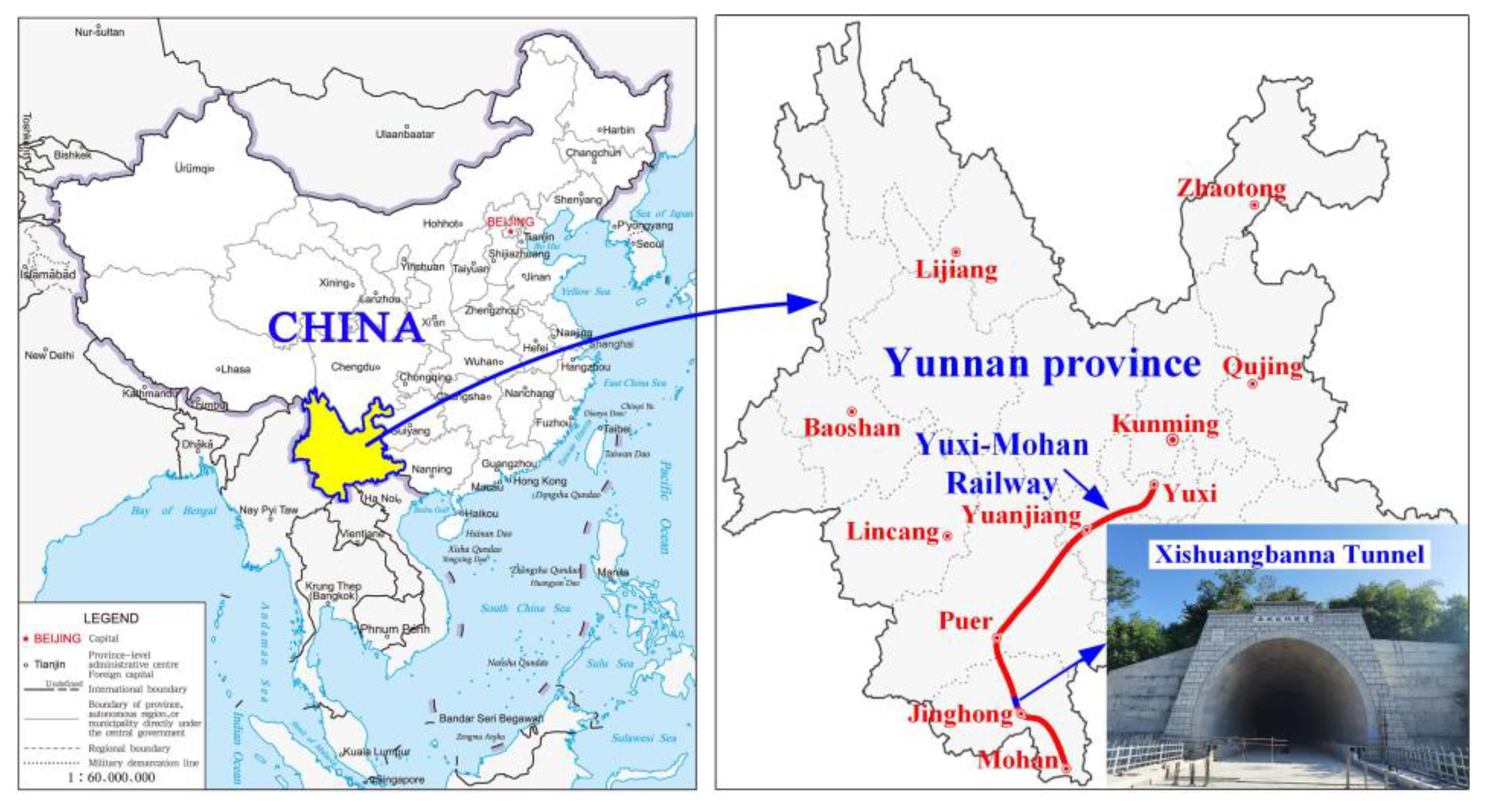
2. Project Description

This study focuses on the Xishuangbanna Tunnel, a vital part of the Yuxi-Mohan Railway project. This section introduces the project overview and construction scheme, including tunnel location, surrounding rock conditions, geological structures, construction methods, and support parameters.

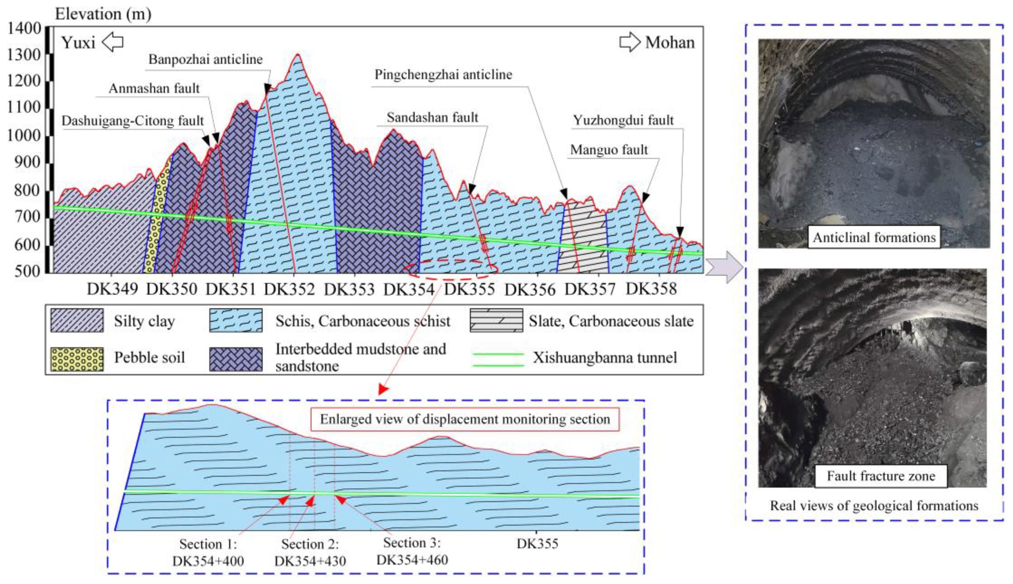
2.1. Engineering Overview

The Xishuangbanna tunnel is located in the Xishuangbanna Dai Autonomous Prefecture, Yunnan Province (Figure 1), with a total length of 10.68 km, a double-line tunnel, and a burial depth between 20 m and 750 m. The exposed surrounding rock shows that the tunnel is dominated by Class IV and Class V surrounding rock, with Class V surrounding rock accounting for 70.6% of the total tunnel length. The design life of the tunnel is 100 years. In conducting on-site monitoring research, the tunnel had yet to be operated. Therefore, the influence of train loads was not considered in this study.
Figure 2 elegantly illustrates the geological profile of the Xishuangbanna Tunnel. This region has five fault lines and two anticlinal formations oriented towards the northwest, indicating dynamic geological structural movements. The geological composition of the encompassing rock in the Xishuangbanna tunnel predominantly comprises schist, carbonaceous schist, and carbonaceous slate, presenting as delicate to moderately substantial layers, with thicknesses spanning from approximately 0.01 to 0.2 m. The surface water in the Xishuangbanna tunnel mainly comes from the Longyang River at the entrance of the tunnel. The aquifer in the surveyed area includes three types: loose rock porous water, fractured rock water, and structural fracture water from the Quaternary system. The predicted normal water inflow of the entire tunnel is about 3.0 × 10⁴ (m3/d), and the maximum water inflow during the rainy season is about 3.6 × 10⁴ (m3/d). Excavation revealed local seepage on the tunnel face, and there were drips on the initial support arch. After excavation, the rock mass became angular and gravelly, and excessive blasting vibration led to block detachment and collapse. Carbonaceous shale is prone to softening and slippage when immersed in water. The vigorous tectonic forces induce conspicuous deformation within the rock mass, marked by slight interlayer folding. The rock formation displays fractures, accompanied by the development of stratification planes and three to five sets of joints and crevice surfaces, exhibiting an average spacing of 0.05 m. Notably, the interconnections between these surfaces are relatively deficient, a point visually underscored in Figure 3.
The hydraulic fracturing method was used for in situ stress measurement. The principle of ground stress measurement using the hydraulic fracturing method involves using a pair of expandable rubber packers. These packers are placed at a predetermined testing depth to isolate a specific borehole section, followed by injecting liquid to apply pressure to this isolated section. The ground stress is calculated based on the pressure characteristic values of the fracturing process curve. The process includes packer setting, water injection and pressurization, rock wall fracturing, pump closure, pressure relief, re-expansion (continuous pressure cycling), unsealing, and recording the direction of fracturing.
The predominant stress on the ground in the test area was caused by tectonic activity. The maximum horizontal ground stress was 18 MPa, and the maximum ratio of the maximum horizontal principal stress to the vertical stress was 1.56, with an average of 1.39. Through uniaxial compression experiments, the saturated compressive strength of rock mass was determined to be RC = 11.9 MPa, and the strength–stress ratio of the rock was RC/δ = 0.66, which is an extremely high ground stress environment [34].

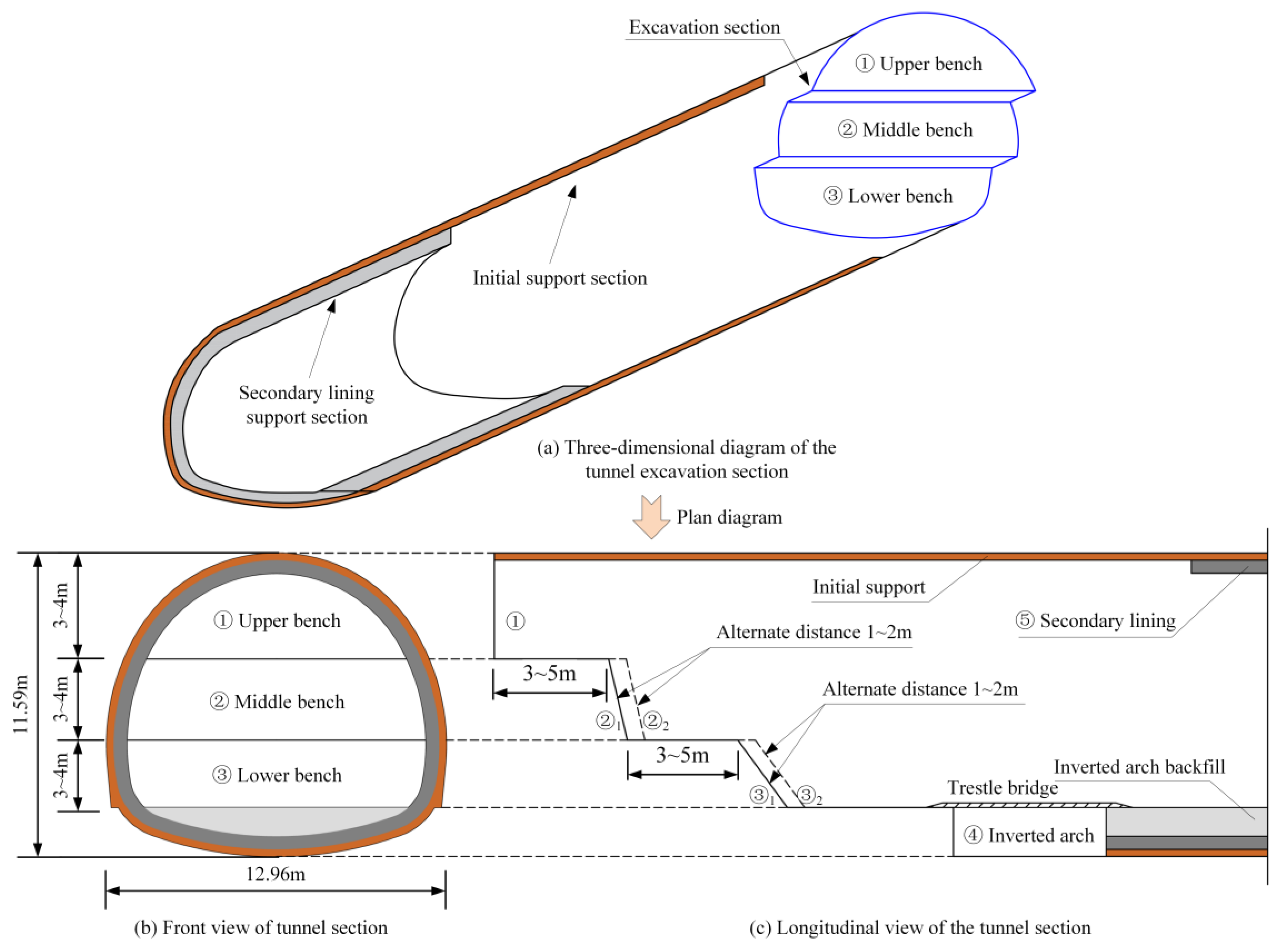
2.2. Construction Scheme

The three-bench method was used to excavate the weak surrounding rock section of the Xishuangbanna tunnel. The excavation footage was 1.2 m, and the deformation allowance was 15 cm. The cross-section and construction sequence of the tunnel are shown in Figure 4. The supporting structure of the tunnel is a composite lining; the primary support adopted shotcrete and a steel arch, and the secondary lining was full-ring reinforced concrete. The supporting parameters are detailed in Table 1.

3. Field Test of Tunnel Deformation Characteristics

The construction and structural safety of the Xishuangbanna tunnel are significantly affected by tectonic movement and high ground stress. This section will survey typical forms of damage during the tunnel construction process. Comprehensive deformation monitoring will be conducted on selected on-site segments to analyze deformation patterns during construction in carbonaceous shale formations.

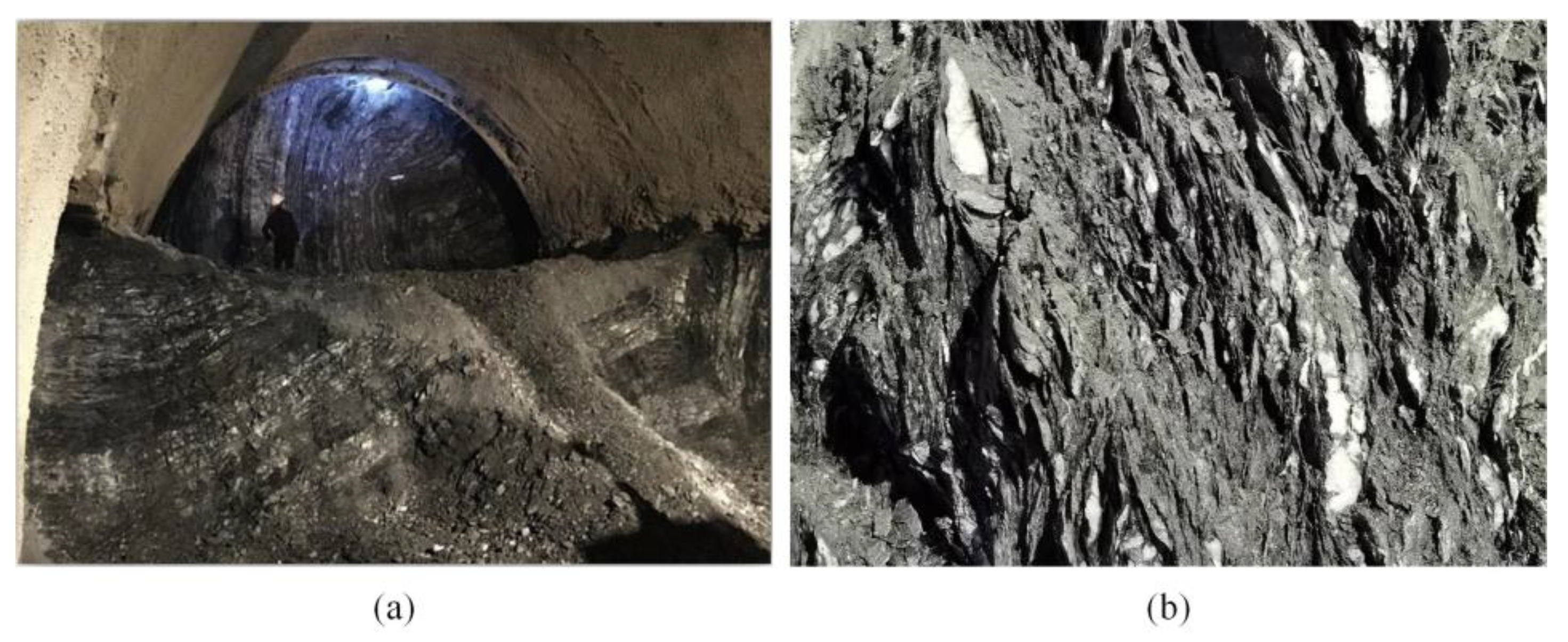
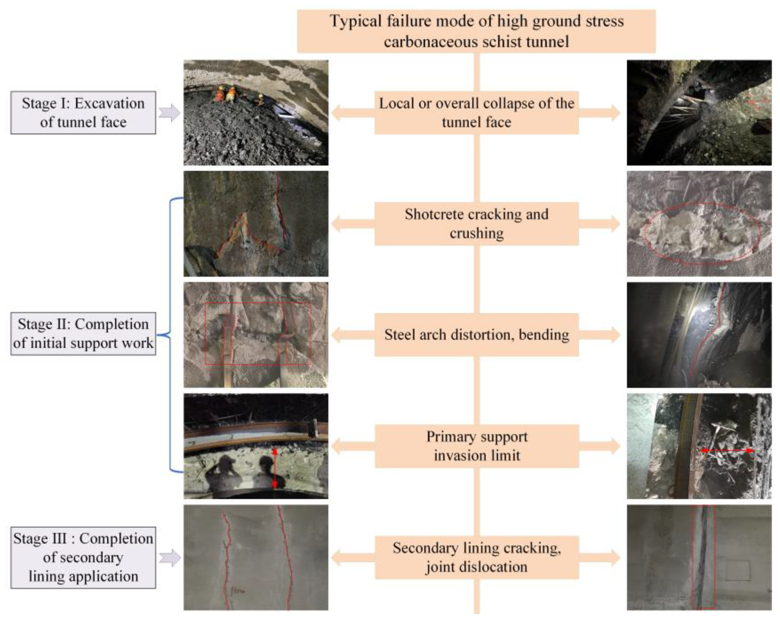
3.1. Failure Modes and Cause Analysis

According to the geological investigation in the early stage of tunnel construction and the statistical results during the construction phase, the tunnel area has not experienced significant earthquakes or large-scale displacements caused by active fault zones. Additionally, in the design of initial support and secondary lining structures, we took into account a significant safety margin and implemented various measures (grouting, enhancing the strength and thickness of the lining concrete, and incorporating a damping layer between the lining and surrounding rock) to enhance the tunnel’s seismic performance. Therefore, this paper focuses on the effects of soil displacement and deformation.
Subject to the dual influence of tectonic movements and high ground stress, the Xishuangbanna tunnel has experienced severe large-scale deformation disasters. This has posed substantial challenges to both tunnel construction safety and structural stability. In order to unravel the destructive characteristics of the high ground stress carbonaceous shale tunnel, a comprehensive survey of the extensive deformations in the Xishuangbanna tunnel was conducted. The main failure modes were classified according to the corresponding construction stage, as shown in Figure 5. Figure 5 illustrates the typical patterns of damage in high-ground-stress carbonaceous schist tunnels. Through on-site investigations, it was discerned that the predominant damage modes encompassed roof strata collapse, initial support cracking, steel frame failure, early support encroachment, and secondary lining fractures. The frequency of occurrence for each failure mode is 13.7% (local or overall collapse of the tunnel face), 19.3% (shotcrete cracking and crushing), 35.0% (steel arch distortion and bending), 23.5% (primary support invasion limit), and 8.5% (secondary lining cracking, joint dislocation). Among these, steel arch failure and primary support invasion were the most frequently occurring forms of damage.
In conjunction with the patterns of tunnel damage, an in-depth analysis of the causative factors behind such impairments is imperative. The root causes of the extensive deformation disasters witnessed in the Xishuangbanna tunnel can be attributed to three primary facets: the characteristics of the surrounding rock, initial ground stress, and the strength of the support system. Firstly, the encompassing rock primarily consists of carbonaceous schist, emblematic of a vulnerable geological stratum. Notably, this geological stratum is densely riddled with joints and fissures and is profoundly fractured due to the influence of structural planes. After excavation, the area is at a high risk of roof strata collapse. The carbonaceous schist exhibits rheological properties, which emerge as pivotal factors in the occurrence of secondary lining damage. Secondly, the tunnel is situated within an environment characterized by high ground stress, a pivotal factor leading to a spectrum of large-scale deformation disasters post-excavation. These disasters encompass the early-stage development of initial support cracking, the collapse of shotcrete, and the structural failure of steel framework components. Furthermore, in the early stages of tunnel support design, I20b steel arches spaced at 80 cm intervals were primarily employed as the load-bearing structures, supplemented by anchoring bars to fortify the arch walls. However, the absence of radial grouting in these arch walls led to an inadequacy in the initial support system’s strength.

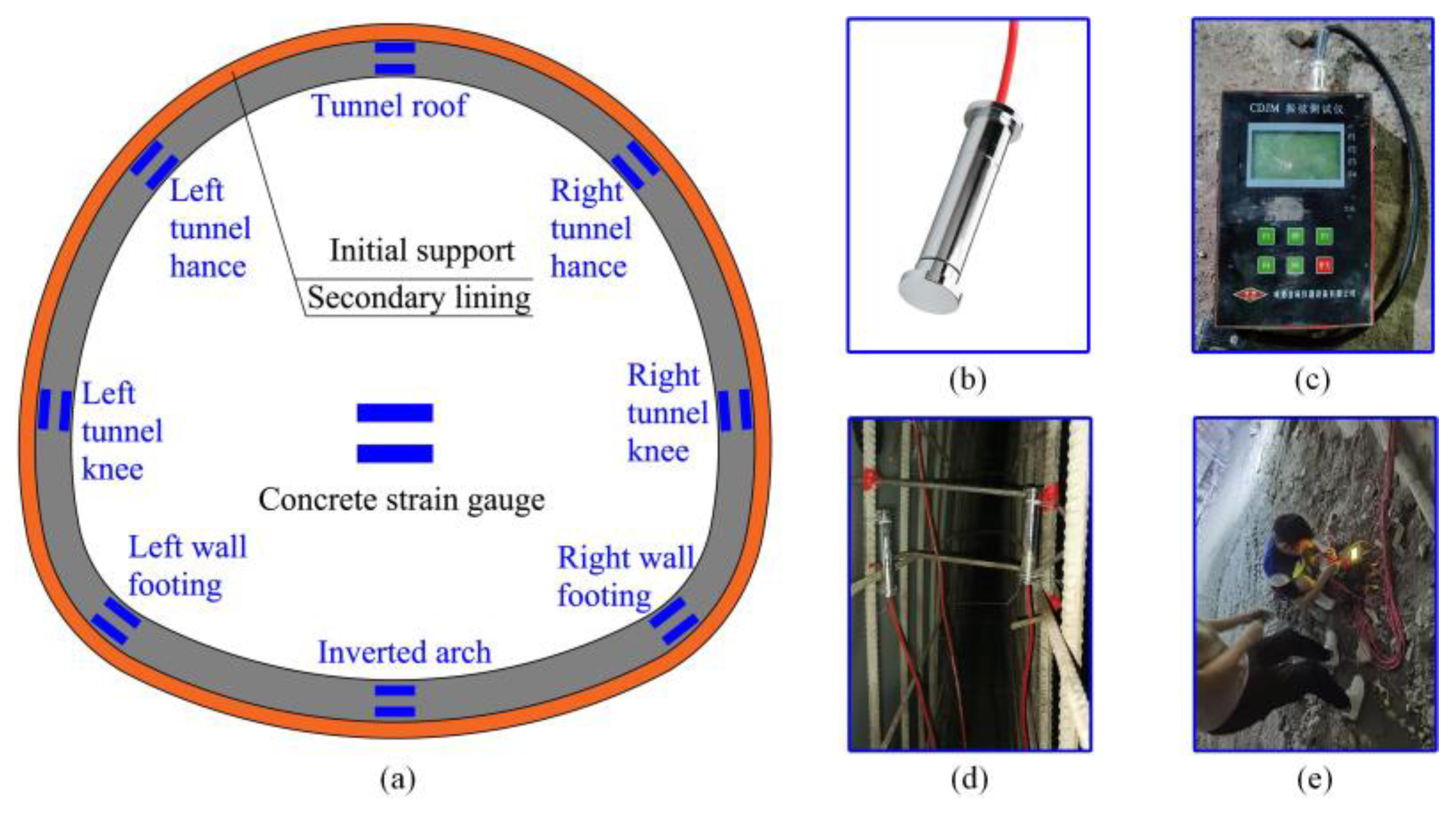
3.2. Layout of Monitoring Points

A comprehensive deformation monitoring scheme was implemented to gain insight into the tunnel’s deformation characteristics, with the arrangement of monitoring points as depicted in Figure 6. Point A is the tunnel vault settlement monitoring point for monitoring the displacement of the tunnel apex in the vertical direction. Meanwhile, monitoring lines designated S1, S2, and S3 were positioned at the upper, middle, and lower bench levels. Designations of S1-1, S1-2, S2-1, S2-2, S3-1, and S3-2 were employed to specify the endpoints of these convergence monitoring lines. The scope of monitoring encompassed assessments of both the arch crown settlement and tunnel perimeter convergence.

3.3. Field Test Results

In the construction area of the Xishuangbanna tunnel crossing carbonaceous schist, three characteristic sections of DK354 + 400 (Section 1), DK354 + 430 (Section 2), and DK354 + 460 (Section 3) were selected for tunnel deformation analysis, as shown in Figure 2. The Monitor Measurement Technology was used to track the deformation of each section. The deformation and deformation rate time–history curves of the three characteristic sections are shown in Figure 7.
It can be seen from Figure 7 that the tunnel deformation is large. The values measured at points S1 to S3 are positive, indicating that the tunnel has converged horizontally. The peripheral convergence is larger than the vault settlement due to the influence of horizontal ground stress. The peripheral convergence of the upper bench is the largest, with a maximum convergence of 629.6 mm and a maximum settlement of 505 mm. The deformation rate is high, the maximum convergence rate is larger than the maximum settlement rate, the maximum convergence rate is 40.20 mm/d, and the maximum settlement rate is 32.40 mm/d. The deformation lasts for a long period and does not stabilize for nearly two months. The cumulative deformation of each section exceeds the deformation allowance of 15 cm, and the primary support seriously invades the limit.
Excavation activities significantly influence tunnel deformation, and distinct trends in deformation development emerge. Following the excavation of the upper bench, the surrounding rock undergoes deformation at a relatively high rate, leading to a rapid accumulation of deformation. Subsequently, after the lower bench excavation is completed, typically within 2 to 3 days, the deformation rate in the surrounding rock diminishes, yet deformation continues to occur. When the construction of the inverted arch is carried out and the initial support is closed, usually 3 to 4 days after, the deformation rate notably decreases, and the cumulative tunnel deformation increases gradually. Consequently, based on the changing gradients of these curves, the evolution of tunnel deformation can be divided into three distinct stages: the rapid deformation stage (Stage 1), the sustained deformation stage (Stage 2), and the gradual deformation stage (Stage 3):
(1)
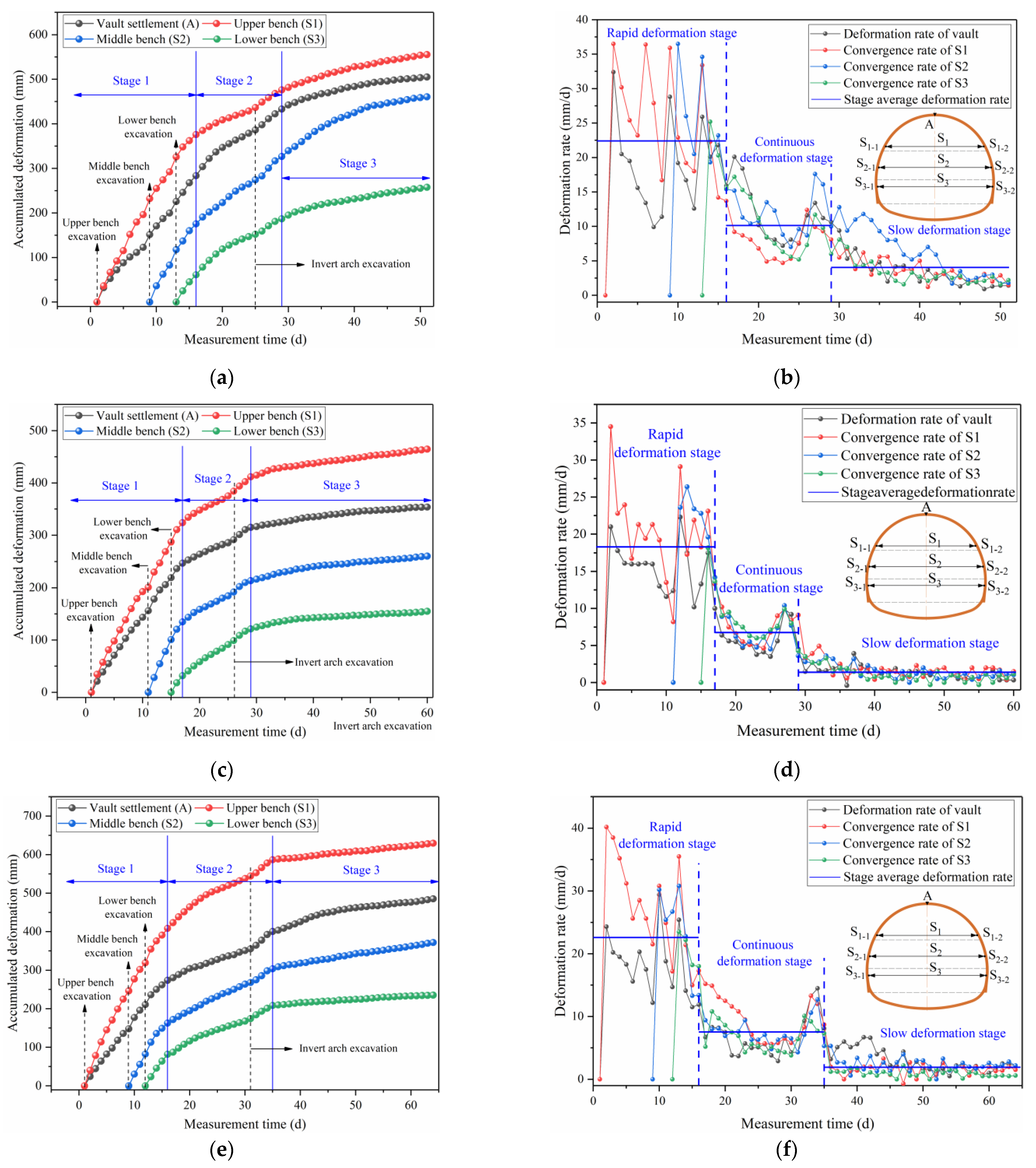
Rapid deformation stage: the excavation of the upper bench to 2~3 days after lower bench excavation. The maximum deformation rates of the three sections are 36.50 mm/d, 34.50 mm/d, and 40.20 mm/d, respectively, and the average deformation rates are 22.41 mm/d, 18.31 mm/d, and 22.60 mm/d, respectively.
(2)
Continuous deformation stage: 2~3 days after lower bench excavation to 3~4 days after the inverted arch excavation. The initial support is closed in this stage, and the deformation rate is significantly reduced compared with the rapid deformation stage. However, due to the low strength of the inverted arch at this time, the bearing capacity of the initial support is relatively limited, and the deformation rate is still significant. The average deformation rates of the three sections are 10.13 mm/d, 6.76 mm/d, and 7.54 mm/d, respectively.
(3)
Slow deformation stage: after 3~4 days of inverted arch excavation. In this stage, the supporting capacity of the initial support is greatly improved, and the deformation rate is reduced to a negligible level. However, under the influence of unfavorable factors such as the rheological behavior of the surrounding rock, high ground stress, and insufficient support strength, the tunnel still deforms slowly at a specific deformation rate. The average deformation rates of the three sections are 4.04 mm/d, 1.39 mm/d, and 1.92 mm/d, respectively.
According to Figure 7, the cumulative deformation in the rapid deformation (Stage 1) and sustained deformation (Stage 2) stages reaches nearly 90% of the maximum deformation, indicating that tunnel deformation primarily occurs in the first two deformation stages. Combining the deformation rate–time curves, the average settlement rates for Sections 1 to 3 in the first two deformation stages are 15.47 mm/d, 11.25 mm/d, and 11.78 mm/d, respectively. The average convergence rates (S1) for Sections 1 to 3 in the first two deformation stages are 17.00 mm/d, 14.70 mm/d, and 17.26 mm/d, respectively. The convergence rate is significantly higher than the settlement rate, indicating that the vertical deformation differs from the horizontal convergence, as demonstrated by the greater deformation of the lateral convergence compared to the tunnel arch within the same time frame. Furthermore, comparing the convergence rates of S1, S2, and S3, it is evident that there are significant differences in deformation rates among the three sets of measurement lines in the rapid deformation (Stage 1) and sustained deformation (Stage 2) stages. This indicates that the lateral convergence deformation processes differ at the three bench levels of the tunnel cross-section. As a result, there is a significant asymmetry in tunnel deformation.
In order to investigate the relationship between tunnel deformation and excavation steps, based on the maximum deformation value of the same section, the deformation ratios of vault settlement and peripheral convergence (S1) at the beginning of each key excavation step were calculated, as shown in Table 2.
According to Table 2, before the middle bench excavation, the average settlement value of the three sections accounted for 34.86%, and the average convergence value accounted for 41.01%. Before the lower bench excavation, the average settlement and convergence values were 50.06% and 57.07%, respectively. Before the inverted arch construction, the average settlement and convergence values accounted for 77.38% and 84.21%, respectively. Therefore, from the upper bench excavation to the middle bench excavation, the cumulative settlement value and the cumulative convergence value accounted for about 35% and 41% of the total deformation of the monitoring, respectively. After the middle bench excavation to before the lower bench excavation, the settlement and convergence values increase by about 15% and 16%, respectively. After the lower bench excavation to the inverted arch excavation, the settlement and convergence values increased by about 27%. After the inverted arch excavation and the closure of the initial support, the settlement and convergence accounted for about 23% and 16% of the total deformation monitored.
It can be seen from this that when the three-bench method is used for tunnel construction in carbonaceous schist strata under high ground stress, the cumulative deformation of the tunnel before the middle bench excavation accounts for the largest proportion, indicating that the upper bench excavation has the greatest impact on the deformation and that the early deformation of the tunnel is large. The proportion of deformation from the lower bench excavation to before the inverted arch excavation is the second, and the deformation after the inverted arch excavation accounts for the smallest proportion.

4. Supporting Time Analysis of Secondary Lining

This section introduces the displacement release rate η, which helps determine the self-supporting capacity of the surrounding rock and stress release due to deformation over time. It proposes a method for determining the timing of secondary lining support suitable for tunnels with large deformations. By analyzing the on-site deformation monitoring data and taking into account the stress characteristics of the secondary lining, the optimal timing for secondary lining support in the Xishuangbanna tunnel is determined.

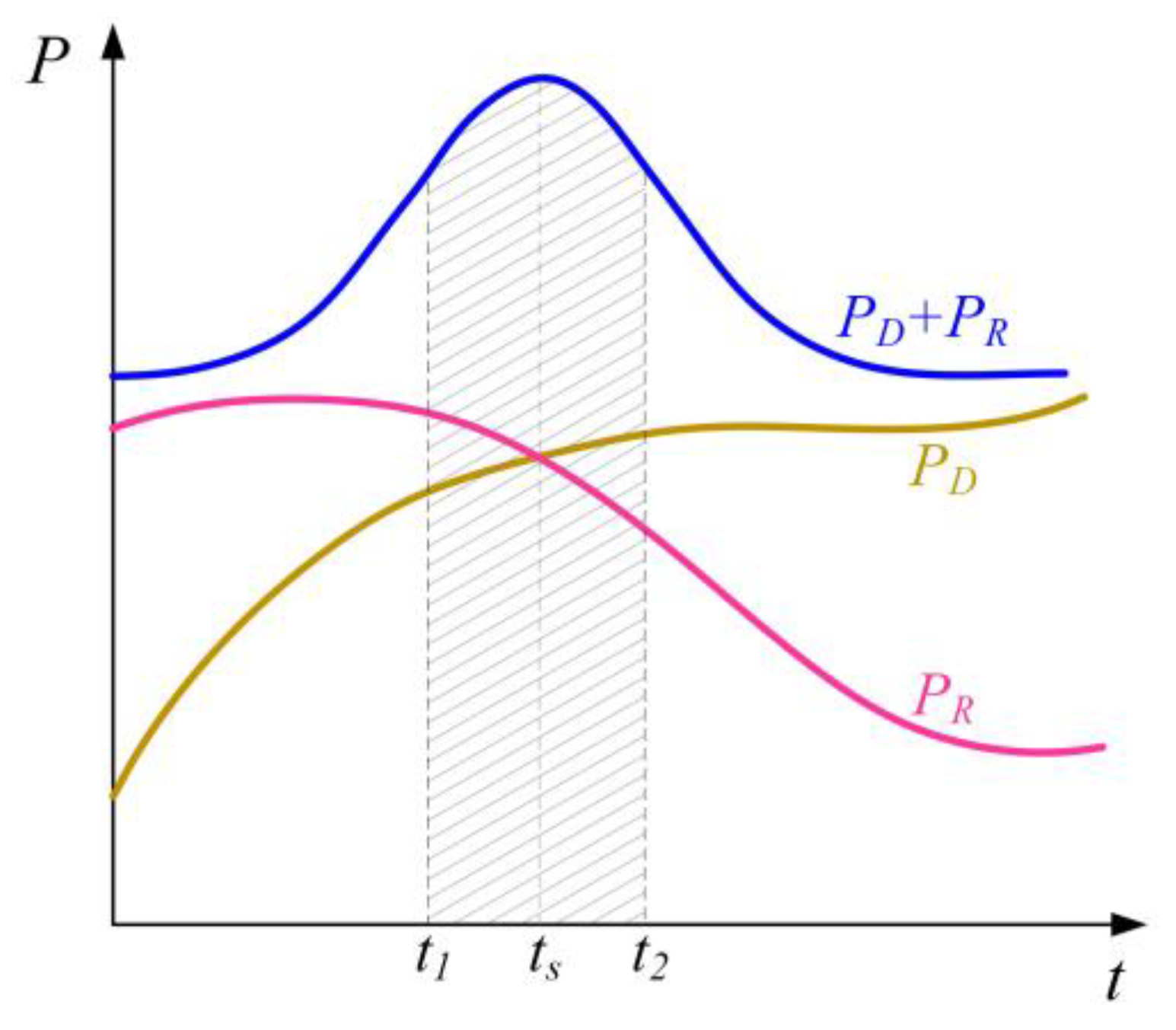
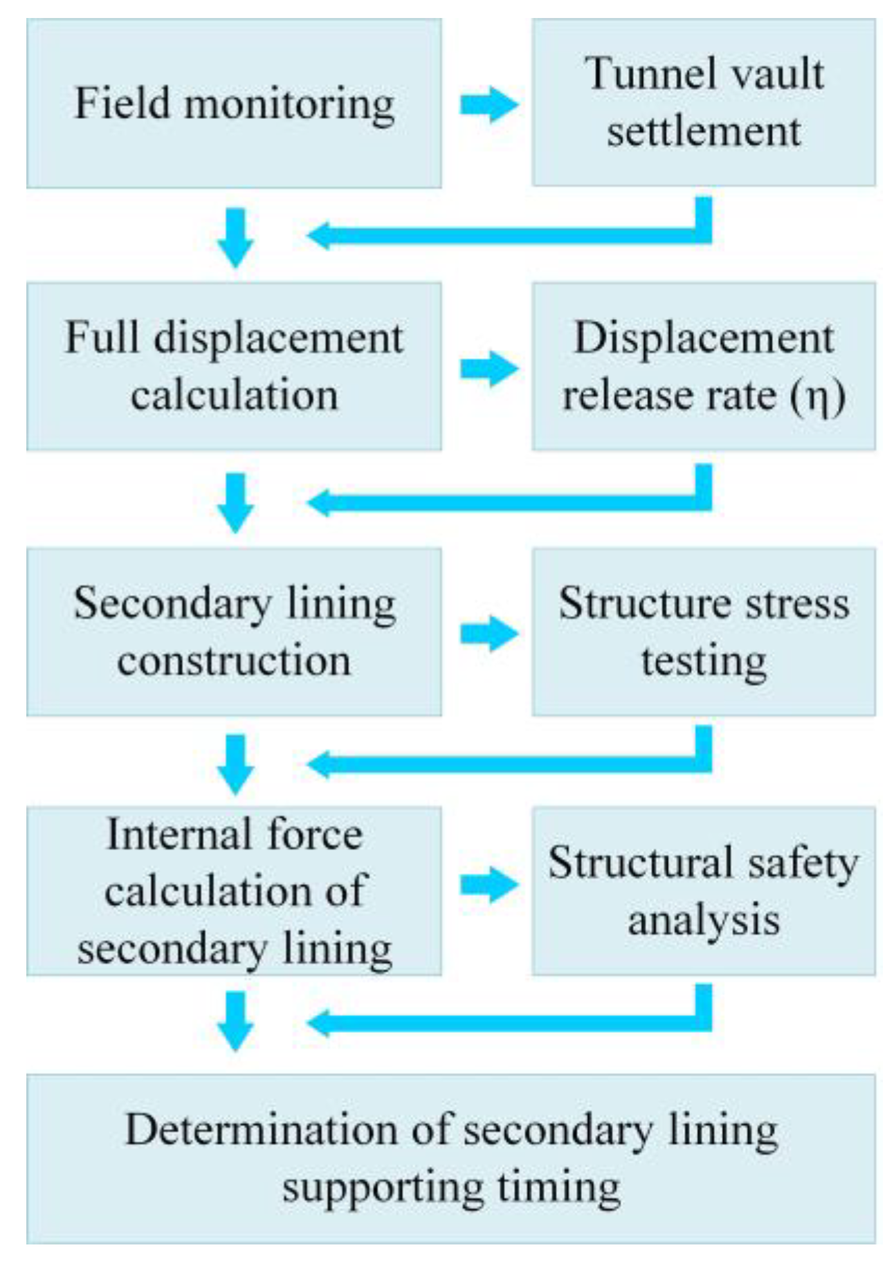
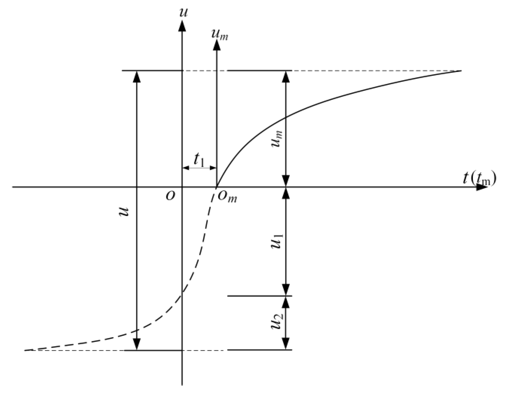
4.1. Determination Method of Supporting Time

The New Austrian Tunnelling Method (NATM) is widely used in tunnel construction. On the one hand, the NATM controls the deformation of the surrounding rock through shotcrete-bolt support, and on the other hand, it gives full play to the self-supporting capacity of the surrounding rock [35]. Therefore, for the weak surrounding rock tunnel constructed by the NATM, it is essential to determine the reasonable supporting time of the secondary lining. After tunnel excavation, the relationship between the self-supporting capacity (PR) of the surrounding rock and the stress (PD) released by the deformation with time is shown in Figure 8. When PD + PR reaches the maximum value, the corresponding time (ts) is the best supporting secondary lining. At this time, the self-supporting capacity of the surrounding rock is fully utilized, and the load on the secondary lining is the smallest. However, in practical engineering, due to the complexity of the construction process, it is often difficult to determine the best supporting time. Therefore, the supporting time of the secondary lining can be determined as the best supporting period (t1, t2).
PR and PD cannot be directly obtained during the construction process; this undoubtedly increases the difficulty of determining the supporting time of the secondary lining. However, both PR and PD are related to tunnel deformation. The deformation of the tunnel can be characterized by the displacement release rate (η), which is the ratio of the actual displacement to the full displacement. Thus, the best secondary lining supporting time can be determined by seeking the best displacement release rate (η). The purpose of determining the supporting time of the secondary lining is to ensure the safety of the tunnel structure. So, when seeking the optimal displacement release rate of the surrounding rock, it is necessary to judge according to structural safety. Based on the above ideas, the method of determining the supporting time of the secondary lining is determined, as shown in Figure 9.
As shown in Figure 9, the first step is to select the test section, monitor the tunnel deformation by Monitor Measurement Technology, and collect data. In the second step, the regression analysis of the monitoring data is carried out to obtain the full displacement under the initial support, and the displacement release rate of the surrounding rock is dynamically grasped. In the third step, when the displacement release rate of the surrounding rock reaches more than 80%, on the premise of ensuring that the displacement release rate of each section is different, the secondary lining is applied, and the stress of the secondary lining concrete is tested. The fourth step is to calculate the internal force of the structure according to the test results of the secondary lining stress and then analyze the structure’s safety by calculating the safety factor. In the fifth step, the structural safety of each section is compared to determine the supporting time of the secondary lining. In short, this method is based on a large number of monitoring and testing data and has high accuracy and reliability. At the same time, the secondary lining supporting time can be dynamically adjusted according to the test results.

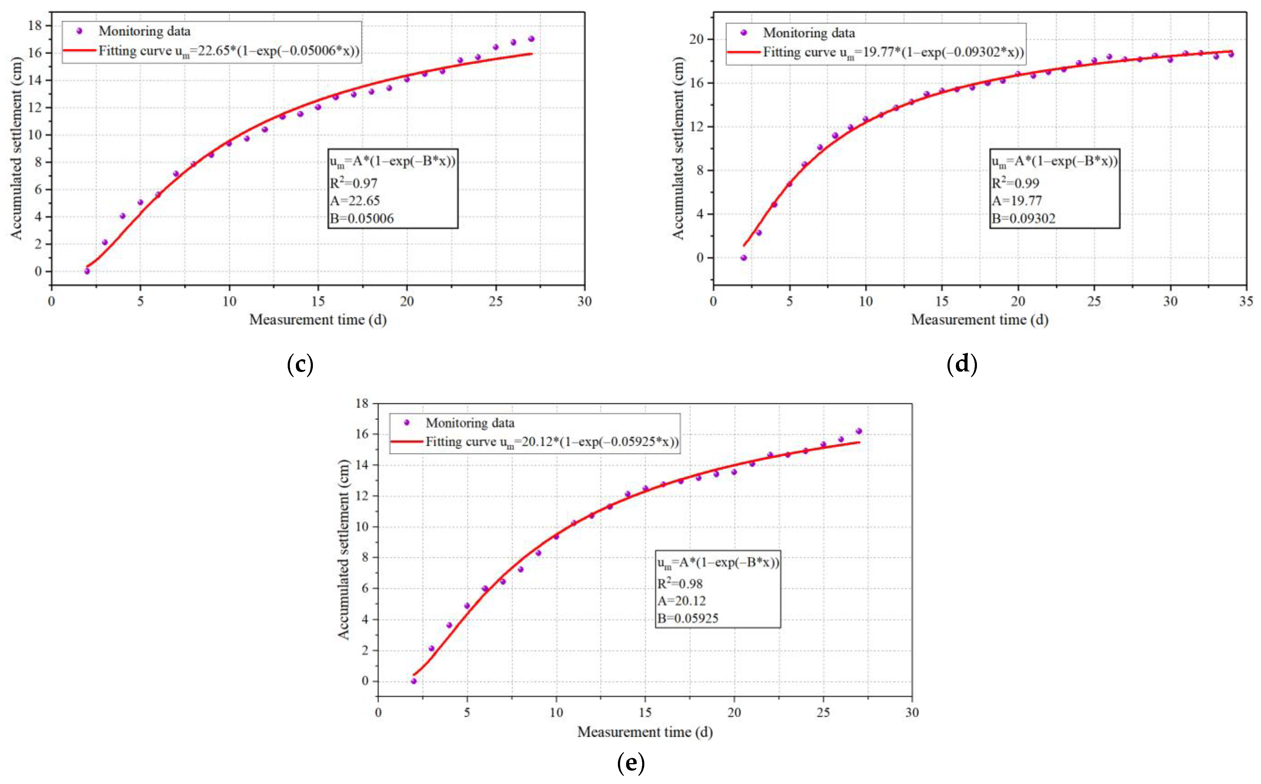
4.2. Full Displacement Calculation of Tunnel

In this section, five tunnel sections were selected for monitoring arch settlement in the large deformation surrounding the rock area. A comprehensive deformation of the tunnel containing all displacements was obtained by conducting regression analysis on the monitoring data and combining it with the theoretical analysis of the entire displacement curve.

4.2.1. Test Sections

According to the analysis of the large deformation characteristics and deformation causes of the Xishuangbanna tunnel, in order to solve the problem of insufficient original support strength, the support structure was adjusted. The adjusted steel arch adopted a I22b I-beam, the spacing was set to 0.6 m, the length of the bolt was adjusted to 4.5 m, and the excavation footage of the tunnel was shortened to 0.8 m. The deformation allowance was adjusted to 30 cm. After adopting the new support scheme, in order to obtain the full displacement of the tunnel deformation, five sections (Case 1~Case 5) were selected to monitor the vault settlement in the large deformation surrounding the rock area of the Xishuangbanna Tunnel, and the monitoring section spacing was 10 m.

4.2.2. Test Results

After the monitoring data are obtained, the exponential function is usually used as the regression function to perform regression analysis on the measured displacement curve, which can reduce the impact of accidental errors and achieve higher regression accuracy [36]. Therefore, this study used the exponential function shown in Equation (1) for regression analysis, where A and B are regression coefficients. A represents the final displacement, and B represents the deformation development characteristics. The deformation monitoring data and fitting curve of five sections are shown in Figure 10; an excellent fitting effect was obtained.
u = A ( 1 e B t )

4.2.3. Full Displacement Calculation

Indeed, on-site monitoring exhibits conspicuous lag characteristics. The surrounding rock has already undergone deformation, known as initial displacement, before tunnel excavation reaches the monitoring section, rendering this portion of displacement unmeasurable. Even when the excavation reaches the monitoring section, it is still impossible to fully measure the entire deformation of the surrounding rock post-excavation, as deformation continues to occur from excavation until the initial data recording period. Hence, it is impossible to derive the complete displacement solely through on-site monitoring, as illustrated by the full displacement curve in Figure 11. Nonetheless, a comprehensive tunnel deformation, encompassing all displacements, can be deduced through regression analysis of the test data combined with theoretical calculations.
Full displacement is calculated as follows:
u = u m + u 1 + u 2
where u is the full displacement; um is the measured part of the displacement caused by excavation; u1 is the unmeasured part of the displacement caused by excavation; u2 is the preexisting displacement before excavation; t1 is the retardation time of the first recorded data during the measurement.
The apparent displacement is the displacement caused by tunnel excavation, namely
u a = u m + u 1
As can be seen from the combination of Equation (1) and Figure 11, when t = ∞, then um = A; when t = −t1, then  u 1 = A ( e B t 1 1 ) . Therefore, the apparent displacement is
u m + u 1 = A e B t 1
The preexisting displacement before excavation is
u 2 = λ 1 λ A e B t 1
The full displacement of the surrounding rock is obtained by Equations (2), (4), and (5):
u = u m + u 1 + u 2 = A 1 λ e B t 1
where A is obtained by fitting the test data (Figure 10);  λ  is an empirical coefficient that characterizes the proportion of pre-existing displacement to full displacement. The value of the empirical coefficient λ mainly depends on the characteristics of the surrounding rock, and its value ranges from 0.265 to 0.33 [37]. The large deformation section of the Xishuangbanna tunnel is Class V surrounding rock; hence, λ is taken as 3 in this paper. The retardation time of the first recorded data during the measurement is 2, that is, t1 = 2.
Based on the monitored data’s regression analysis results, the displacement for each case is calculated using Equation (6) and is shown in Table 3.

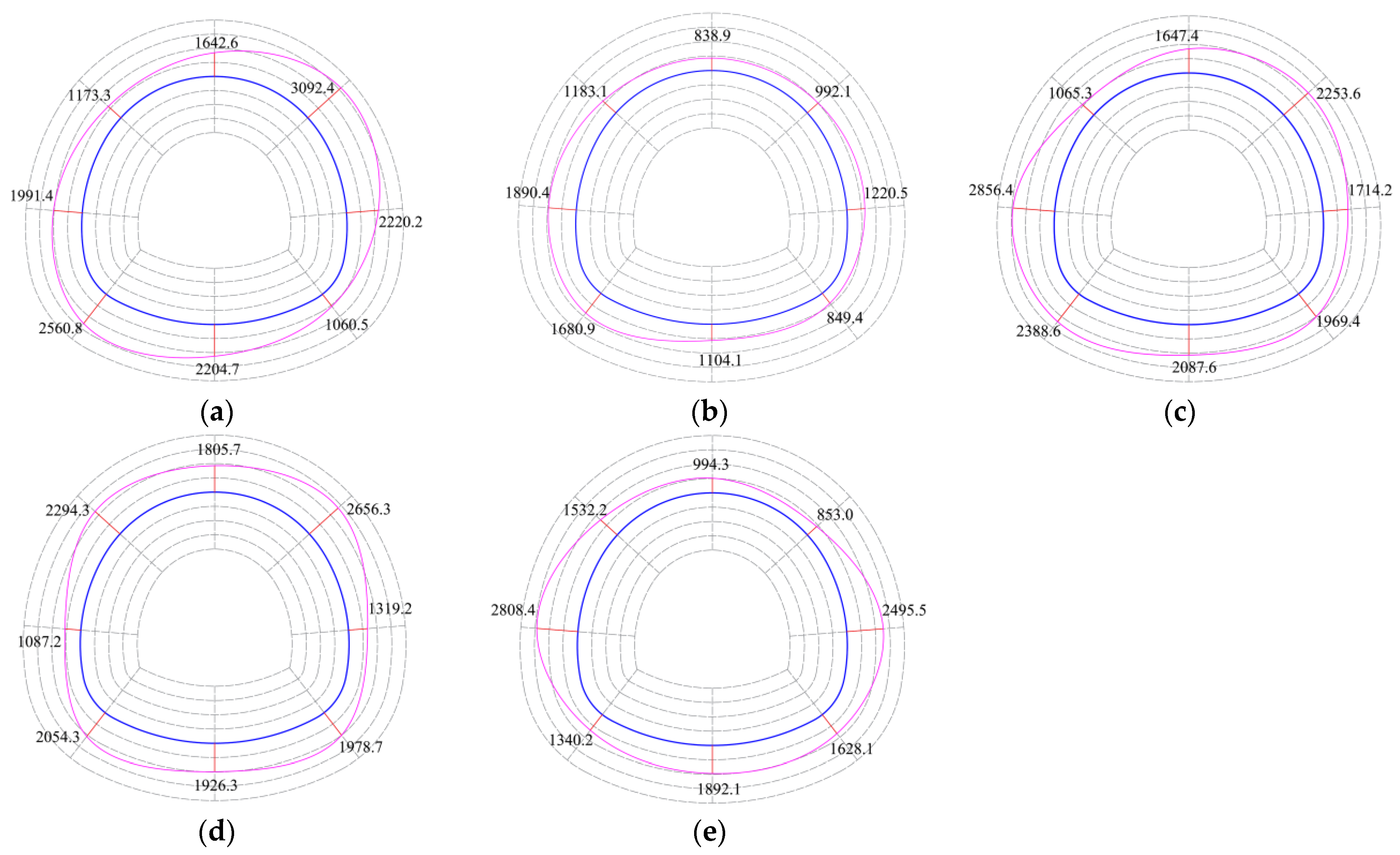
4.3. Field Test of Secondary Lining Internal Force

In order to carry out long-term monitoring of the internal stress of the secondary lining, concrete strain gauges were installed at the key positions of the tunnel. The accuracy of the concrete strain gauge used in the test meets ± 0.1% F.S., and the tensile and compressive measurement ranges are 0~800  μ ε  and 0~1200  μ ε , respectively. The concrete strain gauges were installed in pairs, on the inside and outside of the same position. The layout scheme of the strain gauge and field test are shown in Figure 12.
The vibration wire tester was used for data acquisition. When the strain test data reaches a constant value and shows no significant changes for a consecutive period of 15 days, it is considered that the strain reading has stabilized. After the concrete strain data were stable, the secondary lining’s bending moment and axial force were calculated according to Equations (7) and (8), and the safety factor of the secondary lining was further calculated. The safety factor judges the safety of the secondary lining. The calculation results of axial force, bending moment, and safety factor of the five sections are shown in Figure 13, Figure 14 and Figure 15, where the dark blue line represents the tunnel contour line, and the magenta line represents the bending moment (axial force/safety factor) envelope.
N = 1 2 E ( ε inner + ε outer ) b h
M = 1 12 E ( ε inner ε outer ) b h 2
where  N  represents the axial force, N;  M  represents the bending moment, N·m;  ε inner  and  ε outer  represent the outer strain and inner strain of the secondary lining;  b  represents the unit length, taken as 1 m;  h  represents the thickness of the secondary lining, m;  E  represents the elastic modulus of the secondary lining concrete, Pa.
According to the ‘Code for Design of Railway Tunnel’ [37], the equation for calculating the safety factor is as follows:
K N φ α R a b h
where K is the safety factor; N is the axial force in MN; Ra is the compressive ultimate strength of the lining structure; b is the cross-sectional width in m; h is the cross-sectional thickness in m; φ is the longitudinal bending coefficient, which is set at 1.0 in this context; α represents the eccentricity influence factor of the axial force.
As shown in Figure 13 and Figure 14, the inner side of the tunnel vault and inverted arch is mainly subjected to tension. Due to the significant and local wrinkles in the surrounding rock, the force of the remaining parts has no apparent regularity. According to the axial force diagram, the secondary lining of each test section is in a state of compression. The maximum bending moment and axial force mainly appear in the tunnel hance and knee. The maximum bending moment value is 298.6 kN·m, and the maximum axial force value is 3092.4 kN. The bending moment and axial force for each case are quite different. The reason is that the construction time of the secondary lining is different, resulting in different external loads acting on the secondary lining.
As shown in Figure 15, the minimum safety factors of cases 1 to 5 are 2.20, 5.80, 2.41, 2.50, and 2.50, respectively. From the perspective of structural safety, the safety of case 2 is the highest, and that of case 1 is the lowest, which does not meet the specification requirements (2.40). In the long-term operating environment, there is a safety hazard at the right wall footing of case 1, and it is recommended to strengthen the treatment of this part. At the same time, the minimum safety factor of each test section mainly appears in the left tunnel knee. Therefore, the left tunnel knee is the weak position of the secondary lining, and the construction quality control of the left tunnel knee should be strengthened.

4.4. Secondary Lining Supporting Time

Combined with the above analysis, the secondary lining supporting tunnel time in the carbonaceous schist stratum under high geo-stress is further determined. For the envelope diagram of the safety factor of each section, the minimum safety factor is taken to analyze the safety of the lining structure. The displacement release rate and minimum safety factor of each test section are shown in Table 4.
According to the allowable stress design method, the greater the safety factor of the structure, the safer the structure. Local weak positions often control the safety of tunnel structures. The larger the minimum safety factor of the test section, the safer the secondary lining structure; the lower the minimum safety factor, the more dangerous it is. The relationship between the minimum safety factor of each section and its corresponding displacement release rate is shown in Figure 16.
As seen from Figure 16, with the increase in displacement release rate, the minimum safety factor of the secondary lining gradually increases first and reaches the maximum when the displacement release rate is 90.8%. Then, with the continuous increase of displacement release rate, the minimum safety factor shows a downward trend. This shows that when the displacement release rate is 90.8%, the safety factor of the secondary lining is the highest, which is the best time for secondary lining support. However, it is difficult to grasp the best supporting time at the construction site accurately. Therefore, to ensure sufficient safety of the secondary lining, the displacement release rate of 88~93% can be used as the best supporting period, which is convenient for engineering applications.

5. Conclusions

Deformation monitoring and field tests were carried out on the Xishuangbanna tunnel. Based on the theoretical calculation, the large deformation characteristics and the secondary lining supporting time of the tunnel in carbonaceous schist stratum under high geo-stress were studied in depth. The main research conclusions are as follows:
(1)
In constructing a carbonaceous schist tunnel under high geo-stress, the main failure modes are tunnel face collapse, primary support cracking, steel arch damage, primary support invasion limit, and secondary lining cracking. These failure modes correspond to different construction stages. Among them, steel arch failure and primary support invasion were the most frequently occurring forms of damage. Weak and fragmented strata, high ground stress, and insufficient support strength are the leading causes of large deformations in the tunnel.
(2)
When the three-bench method is used for tunnel construction, the peripheral convergence is significantly greater than the vault settlement. The maximum convergence is 629.6 mm, and the maximum settlement is 505 mm. The early deformation is large, and the deformation rate is high. The maximum convergence rate is 40.20 mm/d, and the maximum settlement rate is 32.40 mm/d. Before the middle bench excavation, the deformation accounts for the largest proportion of the total deformation monitored, about 35~41%. From the lower step excavation to the inverted arch excavation, the deformation accounts for about 27% of the total deformation monitored. After the inverted arch excavation, the deformation accounts for the smallest proportion, about 16~23%. There are differences in the lateral convergence deformations of the three bench levels, and the tunnel deformations show significant asymmetry.
(3)
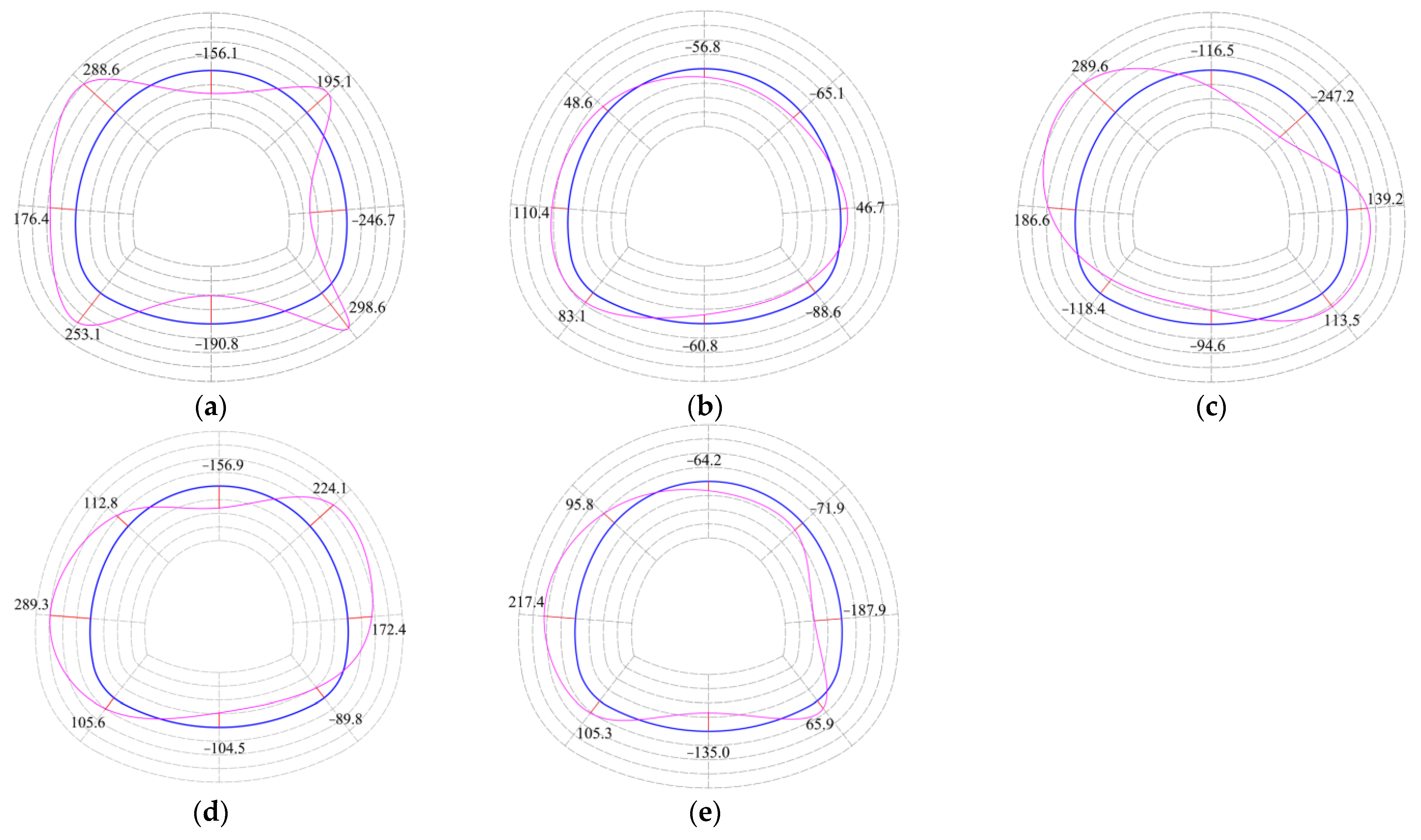
The secondary lining is in a state of compression. The inner side of the tunnel vault and inverted arch is mainly subjected to tension, and the force of the remaining positions has no obvious regularity. The maximum bending moment value and the maximum axial force value mainly appear in the tunnel hance and knee, and the maximum bending moment and axial force can reach 298.6 kN·m and 3092.4 kN, respectively. The left tunnel knee is the weak position of the secondary lining, and it should be strengthened during construction.
(4)
The optimal secondary lining supporting time can be indirectly characterized by the displacement release rate and structural safety factor. With the increase of the displacement release rate, the minimum safety factor of the secondary lining increases first and then decreases. The minimum safety factor is the largest when the displacement release rate is 90.8%. The displacement release rate corresponding to the optimal supporting time of the secondary lining is 90.8%, and the displacement release rate corresponding to the optimal supporting period is 88~93%.
Understanding the inherent deformation mechanisms for tunnels in weak surrounding rock is a crucial prerequisite for implementing effective control measures and preventing structural failures. Therefore, in future work, it is recommended to research the engineering characteristics, disaster-causing influencing factors, and disaster-causing mechanisms of carbonaceous shale formations in order to master the deformation mechanism of carbonaceous schist tunnels and to provide a basis for the effective control of large deformation in tunnels.

Author Contributions

Conceptualization, Y.T. and B.C.; data curation, Y.T. and Z.L.; formal analysis, Y.T. and B.C.; investigation, Y.T. and Z.L.; methodology, Y.T. and B.C.; resources, B.C.; software, Y.T. and B.C.; supervision, B.C. and Z.L.; visualization, Z.L.; writing—original draft, Y.T. and Z.L.; writing—review and editing, Y.T. and Z.L. All authors have read and agreed to the published version of the manuscript.

Funding

This research received no external funding.

Institutional Review Board Statement

Not applicable.

Informed Consent Statement

Not applicable.

Data Availability Statement

Not applicable.

Conflicts of Interest

The authors declare no conflict of interest.

References

  1. Sun, X.; Jiang, M.; Miao, C.; Wang, J.; Zhang, J. Study on large deformation and failure mechanism of deep buried stratified slate tunnel and control strategy of high constant resistance anchor cable. Eng. Fail. Anal. 2023, 144, 106953. [Google Scholar] [CrossRef]
  2. Yu, W.; Wang, B.; Zi, X.; Guo, X.; Wang, Z. Effect of prestressed anchorage system on mechanical behavior of squeezed soft rock in large-deformation tunnel. Tunn. Undergr. Space Technol. 2023, 131, 104782. [Google Scholar] [CrossRef]
  3. Zhao, Y.; Zhang, Y.; Yang, J.; Sun, R. Geotechnical monitoring and analyses on the stability of highway tunnel constructed in carbonaceous slate stratum. Geotech. Geol. Eng. 2019, 37, 4613–4625. [Google Scholar] [CrossRef]
  4. Chen, J.; Liu, W.; Chen, L.; Luo, Y.; Li, Y.; Gao, H.; Zhong, D. Failure mechanisms and modes of tunnels in monoclinic and soft-hard interbedded rocks: A case study. Ksce J. Civ. Eng. 2020, 24, 1357–1373. [Google Scholar] [CrossRef]
  5. Li, S.; Tan, Z.; Yang, Y. Mechanical analyses and controlling measures for large deformations of inclined and laminar stratum during tunnelling. Geotech. Geol. Eng. 2020, 38, 3095–3112. [Google Scholar] [CrossRef]
  6. Moussaei, N.; Sharifzadeh, M.; Sahriar, K.; Khosravi, M.H. A new classification of failure mechanisms at tunnels in stratified rock masses through physical and numerical modeling. Tunn. Undergr. Space Technol. 2019, 91, 103017. [Google Scholar] [CrossRef]
  7. Do, N.A.; Dias, D.; Dinh, V.D.; Tran, T.T.; Dao, V.C.; Dao, V.D.; Nguyen, P.N. Behavior of noncircular tunnels excavated in stratified rock masse–case of underground coal mines. J. Rock Mech. Geotech. Eng. 2019, 11, 99–110. [Google Scholar] [CrossRef]
  8. Wang, H.; Ren, F.; Chang, Y. Effect of bedding angle on tunnel slate failure behavior under indirect tension. Geomat. Nat. Hazards Risk 2020, 11, 428–445. [Google Scholar] [CrossRef]
  9. Tan, Z.; Li, S.; Yang, Y.; Wang, J. Large deformation characteristics and controlling measures of steeply inclined and layered soft rock of tunnels in plate suture zones. Eng. Fail. Anal. 2022, 131, 105831. [Google Scholar] [CrossRef]
  10. Wu, H.; Fan, F.; Yang, X.; Wang, Z.; Lai, J.; Xie, Y. Large deformation characteristics and treatment effect for deep bias tunnel in broken phyllite: A case study. Eng. Fail. Anal. 2022, 135, 106045. [Google Scholar] [CrossRef]
  11. Zhang, X.; He, M.; Wang, F.; Li, G.; Xu, S.; Tao, Z.; Cheng, W. Study on the large deformation characteristics and disaster mechanism of a thin-layer soft-rock tunnel. Adv. Civ. Eng. 2020, 2020, 8826337. [Google Scholar] [CrossRef]
  12. Chen, Z.; He, C.; Xu, G.; Ma, G.; Wu, D. A case study on the asymmetric deformation characteristics and mechanical behavior of deep-buried tunnel in phyllite. Rock Mech. Rock Eng. 2019, 52, 4527–4545. [Google Scholar] [CrossRef]
  13. Chen, Z.; He, C.; Xu, G.; Ma, G.; Yang, W. Supporting mechanism and mechanical behavior of a double primary support method for tunnels in broken phyllite under high geo-stress: A case study. B Eng. Geol. Environ. 2019, 78, 5253–5267. [Google Scholar] [CrossRef]
  14. Li, L.; Tan, Z. Characteristic and mechanism research for large deformation problem in squeezing-shattered soft rock tunnel. Chin. J. Rock Mech. Eng. 2018, 37 (Suppl. S1), 3593–3603. [Google Scholar] [CrossRef]
  15. Lisjak, A.; Garitte, B.; Grasselli, G.; Müller, H.R.; Vietor, T. The Excavation of a Circular Tunnel in a Bedded Argillaceous Rock (Opalinus Clay): Short-Term Rock Mass Response and Fdem Numerical Analysis. Tunn. Undergr. Space Technol. 2015, 45, 227–248. [Google Scholar] [CrossRef]
  16. Kovari, K. Erroneous concepts behind the new Austrian tunnelling method. Tunn. Tunn. Int. 1994, 26, 38–42. [Google Scholar]
  17. Kovári, K. History of the Sprayed Concrete Lining Method—Part I: Milestones Up to the 1960S. Tunn. Undergr. Space Technol. 2003, 18, 57–69. [Google Scholar] [CrossRef]
  18. Ng, C.W.; Lee, K.M.; Tang, D.K. Three-Dimensional numerical investigations of new austrian tunnelling method (natm) twin tunnel interactions. Can. Geotech. J. 2004, 41, 523–539. [Google Scholar] [CrossRef]
  19. Sun, J.; Hou, X. Underground Structure; Science Press: Beijing, China, 1991. [Google Scholar]
  20. Pacher, F. Deformationsmessungen im versuchsstollen als mittel zur erforschung des gebirgsverhaltens und zur bemessung des ausbaues. In Grundfragen auf dem Gebiete der Geomechanik/Principles in the Field of Geomechanics; Springer: Berlin, Germany, 1964; pp. 149–161. [Google Scholar] [CrossRef]
  21. Kaiser, P.K.; Guenot, A.; Morgenstern, N.R. Deformation of small tunnels—Iv. behaviour during failure. Int. J. Rock Mech. Min. Sci. Geomech. Abstr. 1985, 22, 141–152. [Google Scholar] [CrossRef]
  22. Sulem, J.; Panet, M.; Guenot, A. Closure Analysis in Deep Tunnels. Int. J. Rock Mech. Min. Sci. Geomech. Abstr. 1987, 24, 145–154. [Google Scholar] [CrossRef]
  23. Cai, Y.; Esaki, T.; Jiang, Y. An analytical model to predict axial load in grouted rock bolt for soft rock tunnelling. Tunn. Undergr. Space Technol. 2004, 19, 607–618. [Google Scholar] [CrossRef]
  24. Wang, Z.; Fang, J.; Xia, C.; He, K. A method for determining second lining supporting opportunity in soft rock tunnel. Adv. Mater. Res. 2011, 243–249, 3644–3651. [Google Scholar] [CrossRef]
  25. Zhou, Y.; Liu, J.; Fang, J.; Liu, Q. Numerical simulation for appropriate lining time of tunnel considering rock mass rheological conditions. Rock Soil Mech. 2012, 33, 268–272+279. [Google Scholar] [CrossRef]
  26. Sulem, J.; Panet, M.; Guenot, A. An analytical solution for time-dependent displacements in a circular tunnel. Int. J. Rock Mech. Min. Sci. Geomech. Abstr. 1987, 24, 155–164. [Google Scholar] [CrossRef]
  27. Wang, Z.; Fang, J.; Xia, C.; Bian, Y.; Jin, L. Determination method of supporting time forsecondary lining in tunnel considering rock creep behaviors. Chin. J. Rock Mech. Eng. 2010, 29 (Supp. S1), 3241–3246. [Google Scholar]
  28. Choi, S.O.; Shin, H. Stability Analysis of a Tunnel Excavated in a Weak Rock Mass and the Optimal Supporting System Design. Int. J. Rock Mech. Min. 2004, 41, 876–881. [Google Scholar] [CrossRef]
  29. Feng, J.; Wang, X.; Zhou, Y.; Liu, G.; Liu, K. Study on the Supporting Time of the Secondary Lining of the Highway Tunnel with Weak Surrounding Rock. Iop Conf. Series. Earth Environ. Sci. 2021, 643, 12042. [Google Scholar] [CrossRef]
  30. Zhang, J.; Wang, X.; Wang, S.; Wen, S. Retracted: Study on Construction Time of Secondary Lining for Large Section Shallow Buried Tunnel in Soft Rock. In Proceedings of the 2016 International Conference on Smart City and Systems Engineering (ICSCSE), Zhangjiajie, China, 25–26 November 2016. [Google Scholar] [CrossRef]
  31. Wu, M.; Zhang, Y.; Liu, X.; Li, Y. A Study of the Optimal Supporting Time of Large Span and Flat Multi-Arch Tunnel Based on Site Monitoring. Hydrogeol. Eng. Geol. 2012, 39, 53–57. [Google Scholar] [CrossRef]
  32. Yang, J.; Chen, W.; Zhao, W.; Tan, X.; Tian, H.; Yang, D.; Ma, C. Geohazards of tunnel excavation in interbedded layers under high in situ stress. Eng. Geol. 2017, 230, 11–22. [Google Scholar] [CrossRef]
  33. Cao, C.; Shi, C.; Lei, M.; Yang, W.; Liu, J. Squeezing failure of tunnels: A case study. Tunn. Undergr. Space Technol. 2018, 77, 188–203. [Google Scholar] [CrossRef]
  34. Meng, L.; Huang, Y.; Li, T.; Chen, B.; Zhang, W.; Chen, H.; Li, H. An improved classification method of asymmetrical squeezing large deformation of layered soft rock tunnels under high geo-stresses. Chin. J. Rock Mech. Eng. 2022, 41, 147–156. [Google Scholar] [CrossRef]
  35. Chen, B.; Zhang, Z.; Tan, Y.; Liu, Y. Study on structural mechanical characteristics and safety warning of NATM tunnel in aquifer. Mar. Georesources Geotechnol. 2022, 27, 1–16. [Google Scholar] [CrossRef]
  36. Wang, J. Discussion on monitoring and measurement issues in tunnel engineering. Mod. Tunn. Technol. 2008, 45 (Supp. S1), 7–14. [Google Scholar] [CrossRef]
  37. National Railway Adiministtration of the People’s Republic of China. Code for Design of Railway Tunnels, 3rd ed.; China Railway Publishing House: Beijing, China, 2005. [Google Scholar]
Figure 1. Geographical location of Xishuangbanna tunnel.
Sustainability 15 14278 g001
Figure 2. Geological profile of Xishuangbanna tunnel.
Sustainability 15 14278 g002
Figure 3. Surrounding rock condition of tunnel face. (a) Overall situation of tunnel face. (b) Local characteristics of tunnel face.
Sustainability 15 14278 g003
Figure 4. Tunnel cross-section and three-bench method construction sequence.
Sustainability 15 14278 g004
Figure 5. Main failure modes (classified according to construction stages).
Sustainability 15 14278 g005
Figure 6. Layout of deformation monitoring points.
Sustainability 15 14278 g006
Figure 7. Characteristic section deformation and deformation rate time–history curve. (a) The deformation curve of Section 1. (b) The deformation rate curve of Section 1. (c) The deformation curve of Section 2. (d) The deformation rate curve of Section 2. (e) The deformation curve of Section 3. (f) The deformation rate curve of Section 3.
Sustainability 15 14278 g007
Figure 8. The best supporting time (period).
Sustainability 15 14278 g008
Figure 9. Determination method of secondary lining supporting time.
Sustainability 15 14278 g009
Figure 10. Vault settlement test data and fitting curve. (a) Case 1: DK356 + 260. (b) Case 2: DK356 + 270. (c) Case 3: DK356 + 280. (d) Case 4: DK356 + 290. (e) Case 5: DK356 + 300.
Sustainability 15 14278 g010aSustainability 15 14278 g010b
Figure 11. Full displacement curve.
Sustainability 15 14278 g011
Figure 12. Test layout and field test. (a) Site installation. (b) Concrete strain gauge. (c) Vibration wire tester. (d) Site installation. (e) Data acquisition.
Sustainability 15 14278 g012
Figure 13. Axial force of secondary lining: (a) Case1: DK356 + 260. (b) Case 2: DK356 + 270. (c) Case 3: DK356 + 280. (d) Case 4: DK356 + 290. (e) Case 5: DK356 + 300 (unit: kN).
Sustainability 15 14278 g013
Figure 14. Bending moment of secondary lining: (a) Case1: DK356 + 260. (b) Case 2: DK356 + 270. (c) Case 3: DK356 + 280. (d) Case 4: DK356 + 290. (e) Case 5: DK356 + 300 (unit: kN·m).
Sustainability 15 14278 g014
Figure 15. Safety factor of secondary lining. (a) Case1: DK356 + 260. (b) Case 2: DK356 + 270. (c) Case 3: DK356 + 280. (d) Case 4: DK356 + 290. (e) Case 5: DK356 + 300.
Sustainability 15 14278 g015
Figure 16. Relationship between minimum safety factor and displacement release rate.
Sustainability 15 14278 g016
Table 1. Design parameters of tunnel supporting structure.
Support TypeItemSupport Parameters
Initial supportShotcrete gradeC25
Thickness of shotcrete27 cm
Steel arch typeI20b
Spacing of steel arch80 cm
Bolt typeArch: φ25 combination hollow bolt
Side wall: φ22 mortar bolt
Spacing of bolt120 cm × 100 cm
(circumferential × longitudinal)
Length of bolt3.5 m
Size of steel meshφ8
Spacing of steel mesh20 cm × 20 cm
Secondary liningThickness50 cm
Concrete gradeC35
Invert fillingConcrete gradeC20
Table 2. Accumulative deformation ratio.
Excavation
Step
Middle Bench ExcavationLower Bench ExcavationInverted Arch Construction
Section Vault
Settlement
Peripheral
Convergence
Vault
Settlement
Peripheral
Convergence
Vault
Settlement
Peripheral
Convergence
DK354 + 40030.00%40.67%44.73%58.63%76.50%83.44%
DK354 + 43044.10%43.24%61.99%61.88%82.40%82.69%
DK354 + 46030.48%39.12%43.45%50.70%73.25%86.48%
Average value34.86%41.01%50.06%57.07%77.38%84.21%
Table 3. Calculation results of full displacement.
Monitoring SectionRegression EquationFull Displacement/cm
Case 1: DK356 + 260 u = 15.84 × ( 1 e 0.08433 t ) 26.80
Case 2: DK356 + 270 u = 19.96 × ( 1 e 0.06235 t ) 32.30
Case 3: DK356 + 280 u = 22.65 × ( 1 e 0.05006 t ) 35.80
Case 4: DK356 + 290 u = 19.77 × ( 1 e 0.09302 t ) 34.00
Case 5: DK356 + 300 u = 20.12 × ( 1 e 0.05925 t ) 32.40
Table 4. Displacement release rate and minimum safety factor.
Monitoring SectionMeasured Displacement um/cmTotal Displacement before Secondary Lining Construction
(u1 + u2 + um)/cm
Displacement Releasing Rate η
/%
Minimum Safety Factor
Case 114.8825.8496.42.20
Case 216.9929.3390.85.80
Case 317.2030.3684.82.41
Case 418.0532.2794.92.50
Case 516.0828.3587.53.60
Disclaimer/Publisher’s Note: The statements, opinions and data contained in all publications are solely those of the individual author(s) and contributor(s) and not of MDPI and/or the editor(s). MDPI and/or the editor(s) disclaim responsibility for any injury to people or property resulting from any ideas, methods, instructions or products referred to in the content.

