Article

Design and Experiment of Header Height Adaptive Adjustment System for Maize (Zea mays L.) Harvester

1
College of Biological and Agricultural Engineering, Jilin University, Changchun 130022, China
2
College of Automotive Engineering, Jilin University, Changchun 130022, China
3
Changchun ZhongDa Tractor Manufacturing Co., Ltd., Changchun 130000, China
*
Author to whom correspondence should be addressed.
Sustainability 2023, 15(19), 14137; https://doi.org/10.3390/su151914137
Submission received: 10 August 2023 / Revised: 8 September 2023 / Accepted: 19 September 2023 / Published: 24 September 2023
(This article belongs to the Section Sustainable Agriculture)

Abstract

:
In Northeast China, the maize (Zea mays L.) harvester header height is still manually controlled, and the control precision is poor, which limits the quality of maize harvesting and is unfavorable to the long-term development of agricultural harvesting. This work created an adaptive adjustment method for header height to address this issue. A maize harvester header, an STM32 control unit and key module, a hydraulic adjustment mechanism, and a pressure-wheel profiling device comprise the majority of the system. In this scenario, the proposed pressure-wheel profiling device is mounted to the ridge’s surface and walks along it, delivering real-time data on terrain changes. The terrain change signals are received and processed in real time by the STM32 control unit, which subsequently operates the hydraulic adjustment mechanism to alter the header height. The structural dimensions and operational parameters of the essential components for pressure-wheel profiling device were determined using force analysis. A kinematic analysis of the hydraulic adjusting mechanism was performed, and the expression of the relationship between the displacement of hydraulic cylinder and the header height was obtained. The pressure-wheel profiling device was calibrated, the adaptive adjustment parameter model was constructed, and the PID control technique was employed to achieve automatic header height adjustment. This study analyzed the effects of harvester different forward speeds (1.25, 1.45, 1.65, 1.85, and 2.05 m/s) and different operating modes (open and unopened system) on the test indexes (Errors in the automatic adjustment of header height, Cob loss rate, Coefficient of variation in stubble height). The results revealed that, with the adaptive adjustment system mode on, the average difference between the measured actual header height and the predetermined height was 9.96 mm, the average coefficient of variation in stubble height was lowered by 34.44%, and the average cob loss rate was decreased by 7.98%, both of which may accommodate the needs of maize harvester header height adjustment. This study serves as a reference for the automated design of a maize harvester for monopoly crops.

1. Introduction

Maize (Zea mays L.) harvesters are crucial pieces of agricultural machinery, whose performance has an impact on the sustainable development of agricultural harvest. The maize harvester has a complex structure and need simultaneously perform the operations of walking, cutting, conveying, peeling, and grain gathering [1,2]. As one of the core components of a maize harvester [3], the header height can adapt to different harvesting environments, improve harvesting efficiency, and reduce labor costs, so the entire harvesting process of maize harvester is greatly influenced by the header height [4]. The harvester operating quality is greatly influenced by a number of critical aspects, one of which is the header height [5]. If the header height is set too high, it is difficult to harvest whole plants and only a portion of the cob can be taken, which leads to crop loss [6,7]. On the other hand, lowering the header height too far can easily lead to clogging and damage to the body as the header comes in contact with the ground [8,9]. Therefore, the refinement level in maize harvesting is affected by the header height of the maize harvester.
To increase the uniformity of the header height, extensive study has been done on automatic harvester header height adjustment. The header height adjustment is mostly focused on non-contact and contact [10,11]. Non-contact adjustment is through infrared, ultrasonic, laser and other sensors to directly measure the header height from the ground, and then combined with the hydraulic control system to realize the real-time adjustment of the header height. For example, Sun et al. [12] proposed a method to indirectly measure the header height. This approach produced a trustworthy calculation model based on the inclination sensor and displacement sensor on the body. The operation of the tracked chassis lifting mechanism was evaluated by the calculation model. The results showed that the accuracy of the measurement model developed using this method was high. Zhang Zhenping [13] placed an ultrasonic sensor at the bottom of the back side of header, which paired with a displacement sensor positioned on the hydraulic cylinder to determine header height in real time. The field test findings demonstrated that the study could achieve high-precision control of the header height adjustment. In order to realize the automatic adjustment of the header height, Zhang Cong [14] used a plate array ultrasonic sensor to directly measure the header height from the ground, and designed an automatic control strategy for the header height. The results of the field test indicated that the control error of header height complies with the specifications. An adaptive adjustment system of header height was designed by Liao Yong et al. [15]. The technology uses solenoidal infrared reflection to determine the crop height and a displacement sensor and solenoid valve to lift and lower the header. According to the test results, there is a maximum inaccuracy of 2 cm in the height adjustment of the header, and this height adjustment is now automated.
The contact adjustment is realized by the mechanical imitation device in direct contact with the ground and real-time detection of the ground undulation, in order to achieve automatic adjustment of the header height. For example, in order to modify the header height of a soybean harvester, a platen-linkage profiling mechanism and an adaptive adjustment system were created by Ni et al. [16]. Field performance tests showed that the absolute error between the actual stubble height after harvest and the set profile height was less than 2 mm. Jin Chengqian et al. [17] designed a primary–secondary plate compression mechanism in order to improve the sensitivity of the harvester header to the perception of terrain changes. The profiling mechanism rotates the angle sensor with the terrain. It also sends adjustment commands to the solenoid valve through the control system to control header height. A floating compression profiling mechanism was proposed by Geng Aijun et al. [18], which was capable of walking attached to the ground. By using a profiling mechanism to detect the header height above the ground, the control system may then automatically modify header height using a hydraulic cylinder. The test results of the control system showed that the error between the actual header height and the set height under the automatic control mode was within 20 mm, which met the needs of the control for maize harvester header. Gong Yuanjuan et al. [19] proposed a self-weighted oscillating profiling mechanism in order to realize the automatic adjustment of header height for a sugarcane harvester. The mechanism could be attached to the ground in such a way that the header height was detected and adjusted in real time. According to field tests, the broken head rate could be reduced by 18.5% when the header height was automatically adjusted as opposed to manually adjusted.
In summary, researchers have studied the automatic adjustment of header height of soybean, sugarcane and grain harvesters by contact and non-contact adjustment, but less research has been done on the height adjustment of maize harvesters header in the northeastern ridge culture. The most recent data indicate that in 2022, the Northeast produced 25.9 million tons of maize, or around 22.7% of the total amount produced nationwide [20]. The Northeast plays a significant role in the nation’s food production through maize cultivation. However, the regulation of maize harvester header for Northeast ridge crop is still at the stage of joystick manipulation [21,22], with lower regulation accuracy and efficiency, which restricts the quality of maize harvesting. Therefore, it is crucial to conduct research on the automatic adjustment technology of the maize harvester header height in the ridge culture.
The researchers adjusted the header height using a non-contact method. It was prone to weed and soil clod interference during operation and had poor following ability in the case of sloping terrain [23,24]. Accordingly, this study offered an adaptive adjustment method for the header height and constructed a pressure-wheel profiling device in order to achieve the automatic adjustment of header height for maize harvester in the northeast ridge culture. In order to offer real-time feedback on the topographical changes, the designed profiling equipment was attached to the ridge’s surface and walked on the ridge’s surface. The hydraulic adjustment mechanism and profiling device underwent a theoretical study, and their structural parameters and essential dimensions were identified. The header height control strategy was established using the PID control theory, and the software design for the header height adaptive adjustment system was finished. Harvester forward speed is critical to the quality of harvesting operations. However, previous researchers did not consider the effect of forward speed on the designed leveling system performance [16,18,19], which is not conducive to the comprehensive evaluation of the system performance. In this study, we analyzed the effects of different harvester forward speeds and different operating modes on the test indexes, in order to objectively evaluate the reliability and stability of the designed adaptive leveling system.

2. Materials and Methods

2.1. Overall Program Design of the Adaptive Adjustment System of Header Height

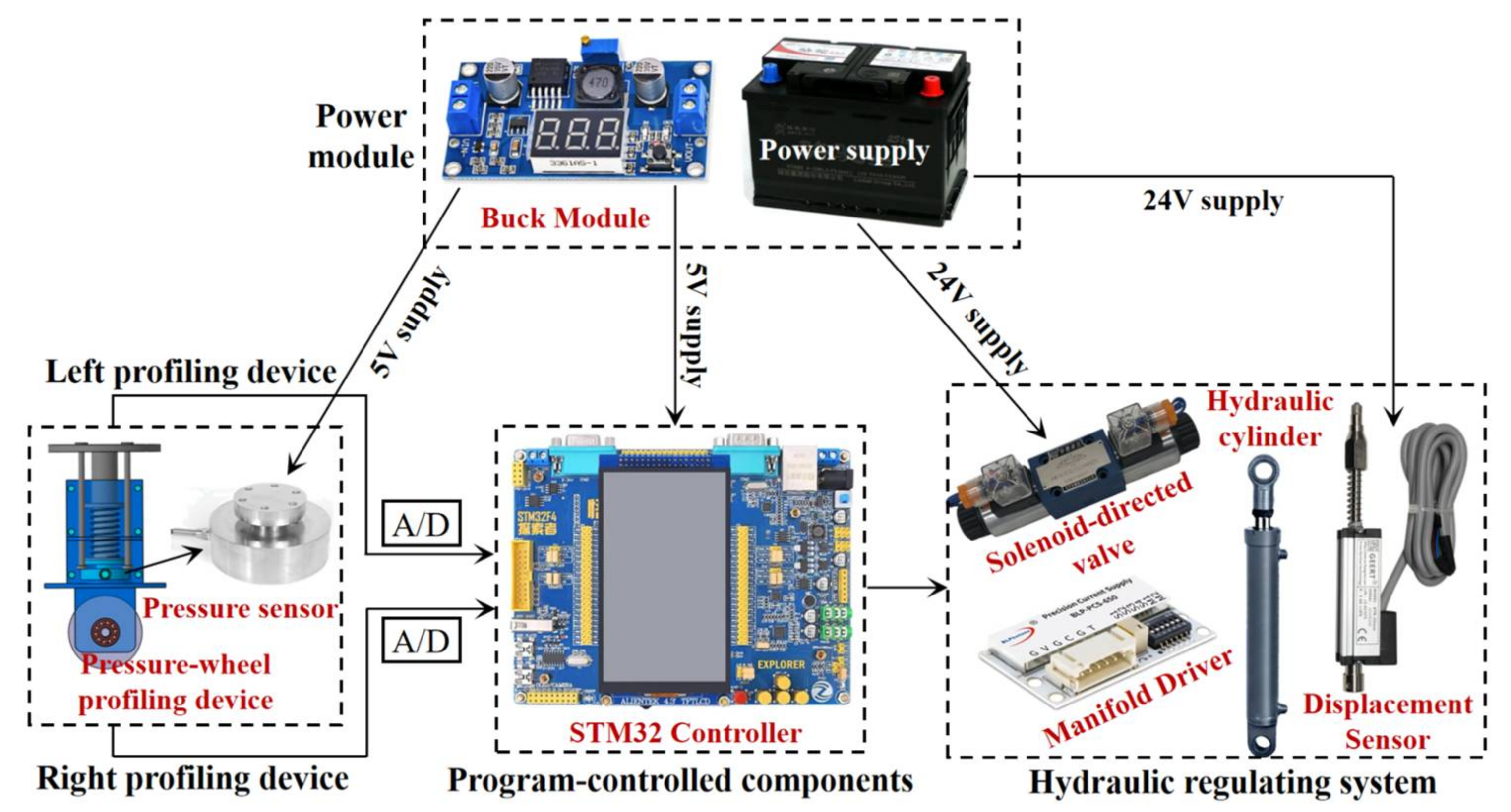
2.1.1. Structure and Composition

Adaptive regulation system of header height was designed to provide adaptive control of maize harvester header height in a ridge crop as well as to reduce the cob loss rate during harvesting operations. In contrast to the conventional manual adjustment mode, adaptive adjustment involves the maize harvester header automatically completing its own height adjustment while it is in operation. The adaptive adjustment system mainly consists of the maize harvester header, STM32 control unit and key module, hydraulic adjustment system, and the pressure-wheel profiling device, as shown in Figure 1.
In conjunction with a buck module, the power supply for the maize harvester supplies 24V DC to the solenoid reversing valves and linear displacement sensors, and 5V DC to the STM32 microprocessor and pressure sensors. The STM32 microcontroller was chosen as the principal controller for the program control section, which processed and converted information between sensors and hydraulic actuators. The pressure-wheel profiling device is mounted under the header by means of a connecting beam, which is mechanically assembled to ensure that it is always perpendicular to the ground. Due to the limited area on the monopoly platform, the pressure-wheel profiling device wandered in field ditch during the harvesting operation. Its pressure-wheel could deform in response to ground undulation, while the acquired data on ground height change was translated into electrical impulses and sent to the program control element. The ground conditions of ridge crop were more challenging; therefore, the profiling device was placed in the same straight line on the left and right sides of the harvester to assure the accuracy of the profiling device in detecting changes in the terrain. A hydraulic tank, a solenoid valve set, and hydraulic cylinders were all part of the hydraulic regulating system. The hydraulic adjustment system adjusted the harvester height cutting table according to the output signal of the microcontroller. According to the microcontroller output signal, the hydraulic adjustment system modified the harvester header height. The components of the adaptive adjustment system for the header height are shown in Figure 2.

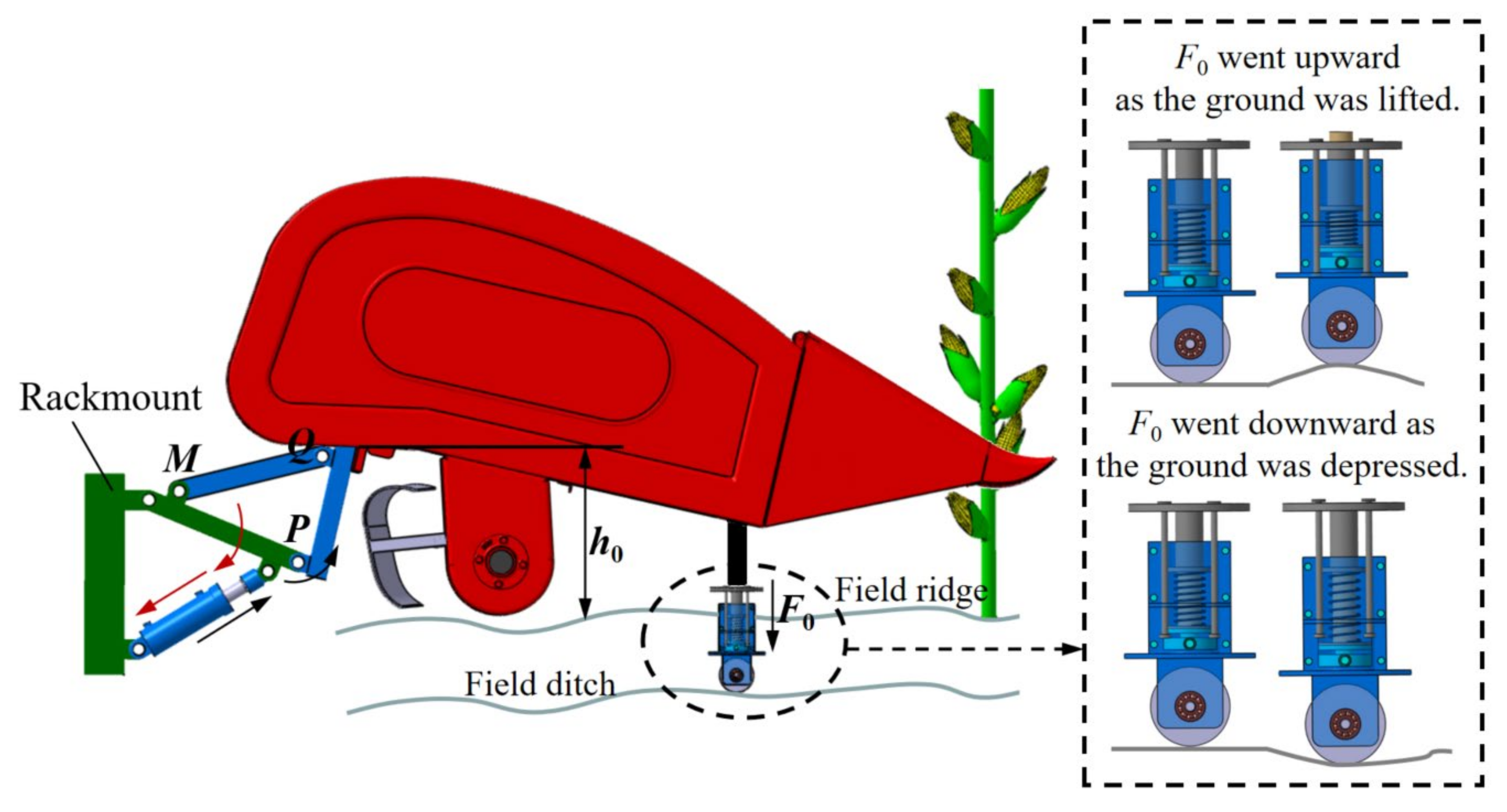
2.1.2. Working Principle

The pressure-wheel profiling device moved on the ridges in the adaptive adjustment system of header height, detecting and feeding back real-time changes in the terrain. To avoid having header height that were too high or too low, the harvester began work with the header set to the optimum height for harvesting activities (i.e., h0). At this moment, the target pressure value (i.e., F0) corresponded to the pre-pressure value corresponding to the profiling device. The pressure-wheel in the profiling device went upward as the ground was lifted, and the regulating spring compressed, increasing F0. The controller directed the solenoid valve to operate in accordance with the pressure value information received. The hydraulic cylinder extended to drive the connecting plate MPQ to rotate counterclockwise, and the header was raised to release the pressure of regulating spring. The pressure value was reset to F0, and the cutter height was reset to h0. Similarly, when the ground was depressed, the pressure-wheel moved downward, and the regulator spring extended to decrease F0. The hydraulic cylinder was shrunk and the connection plate MPQ was turned clockwise to lower the header height under the control of the controller and solenoid valve. After the pressure value of the regulating spring had increased to F0 and the header height had returned to h0, the system stopped working (Figure 3).

2.2. Hardware Design of the Adaptive Adjustment System of Header Height

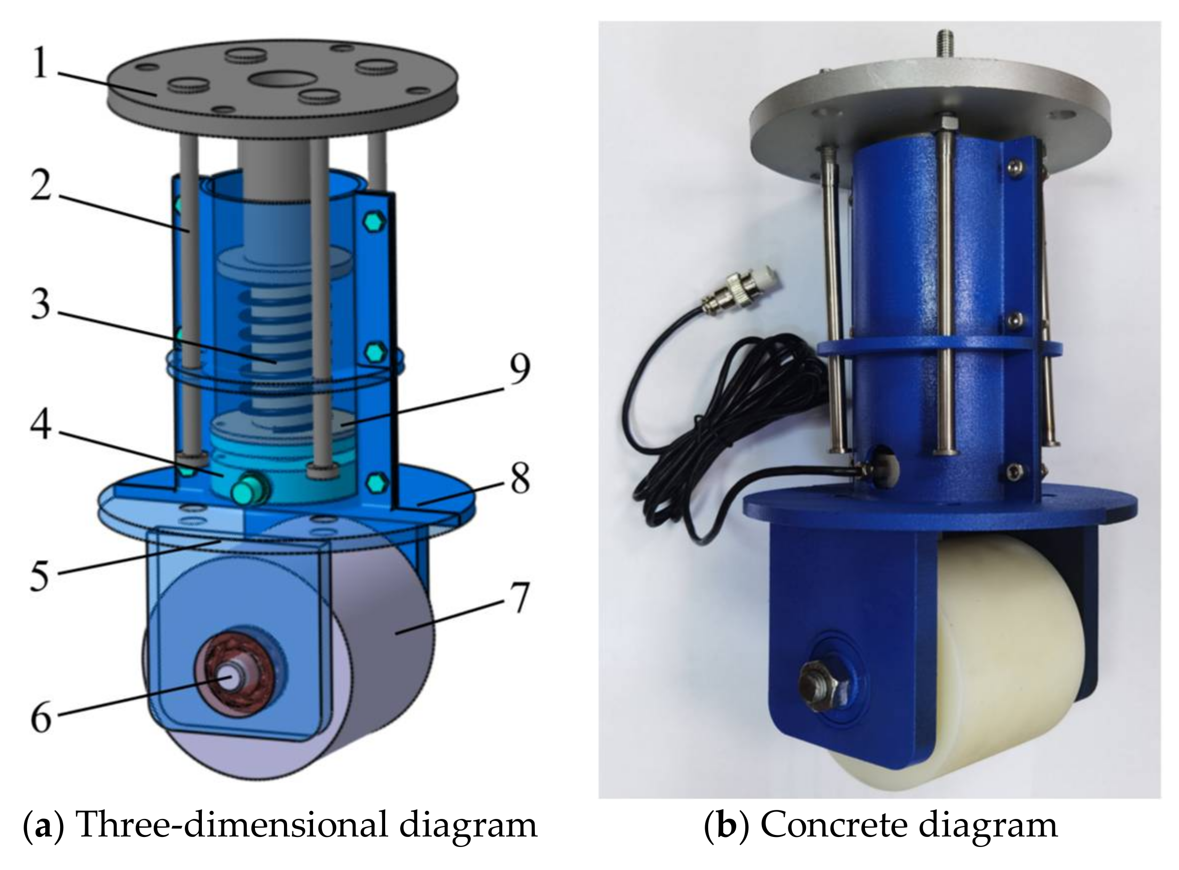
2.2.1. Design of Pressure-Wheel Profiling Device

The pressured plate, connecting rod, regulating spring, pressure sensor, left and right shell plates, the connecting shaft, the pressure-wheel, and the spring pallet make up the pressure-wheel profiling device. A three-dimensional diagram of the device structure is shown in Figure 4a. Bolts were used to attach the left and right side shell plates. Its top portion was hollow, forming a cylinder that housed pressure sensors, a regulating spring, and other parts. The lower half was connected to the pressure-wheel by a connecting shaft. The upper end of the connecting rod was connected to the pressurized plate. The lower end of connecting rod was connected to the left and right side shell plates. Both ends of connecting rod were fitted with limit nuts. The regulating spring was placed on the spring pallet, which had been bolted to the pressure sensor. The physical drawing of the pressure-wheel profiling device is shown in Figure 4b.
The pre-pressure value was directly influenced by the parameters value of the regulating spring, which was a crucial functioning component of pressure-wheel profiling device. The force analysis of the imitation device structure was conducted using the pressure-wheel as the study focal point. As indicated in Figure 5, the x-axis should be parallel to the ground, and the y-axis should be perpendicular to the ground. Several forces were applied to pressure-wheel while it was in use, including the gravity force (G) from the profiling device, the pre-pressure force (F0) from the regulating spring, and dQ, which was the pressure-resistant reaction force of a small segment corresponding to a point on the arc of the pressure-wheel’s soil-touching surface (n1n2). The load on pressure-wheel was equal in magnitude to the total compressive reaction force of the soil. Mechanical equations were established for the press wheel to obtain Equation (1). The force acting on the pressure-wheel had a magnitude equal to that of the soil’s overall compressive reaction force. Equation (1) was obtained by establishing mechanical equations for the pressure-wheel.
F 0 + G d Q cos α 0 = F 0 + G p B d s cos α 0 = 0
where: B is the width of pressure-wheel, p is the soil compressive strength.
From the geometric relationship (ds = cosα0dx), Equation (2) was obtained.
F 0 + G 0 l p B d x = F 0 + G p B l = 0
where: l is the length of the x-axis projection of arc n1n2.
A relational expression for the soil compressive strength (p) was obtained based on the Reece bearing model [25,26].
p = ( c k c + λ s B k φ ) ( Z 0 B ) n
where: c is the cohesiveness of the soil, the dimensionless soil cohesion and friction deformation moduli, respectively, are denoted by the letters kc and kφ, λs is the bulk weight of the soil, Z0 is the degree of soil subsidence, n is the soil deformation index.
An expression for the pre-pressure was obtained from Hooke’s law [27].
F 0 = k F Δ l
where: kF is the stiffness of the regulating spring, Δl is the deformation of the regulating spring.
Equations (3) through (4) were introduced into Equation (2), and after simplification, the final expression (5) was obtained. Because the structure and dimensions of the pressure-wheel profiling device remained unchanged, the mass m0 and width of the pressure-wheel B remained constant. The maize harvester operated in the same plot and under the same soil conditions, therefore the parameters c, kc, kφ, λs and so on remained constant. To summarize, the stiffness and deformation of the regulator spring had a direct impact on the degree of soil subsidence.
k F Δ l + m 0 g B l ( c k c + λ s B k φ ) ( Z 0 B ) n = 0
where: m0 is the mass of pressure-wheel profiling device.
The profiling device went along the ridges, which had a non-rigid road surface. Equation (1) illustrated the computation of the pressure-wheel subsidence based on the prior research basis [28].
Z 0 = 6 ( F 0 + G ) 5 K B D 1 / 2
K = γ ( 1 + 0.27 B )
where: K is the soil characterization coefficient, γ is a parameter related to soil properties.
The expression for the grounding area S of pressure-wheel, as shown in Equation (8), might be derived from the geometric relationship in Figure 5.
S = B D α 0 2 cos α 0 = D 2 Z 0 D
where: α0 is the contact angle, i.e., the angle corresponding to the arc n1n2.
Less hydrophilic polyvinyl fluoride was used to make the pressure-wheel material, which lessened the adhesion effect when it interacted with the ridge soil. Greater hardness was found in polyvinyl fluoride. The distortion of pressure-wheel during operation was so little that it might be considered a rigid body with no discernible elasto-plastic deformation. The soil at the upper edge and center of the grounding surface of pressure-wheel might be regarded as equally compacted. In this manner, the vertical force of pressure-wheel on the ground was dispersed evenly across the contact surface. The final expression for the ground pressure P0 of pressure-wheel is shown in Equation (9).
P 0 = F 0 + G S = 2 k F Δ l + m 0 g D B arccos 1 12 k F Δ l + m 0 g 5 γ ( 1 + 0.27 B ) B D 3 / 2
During spring planting, the earth in the ridge was compressed by the planter ground wheels. The soil property-related parameters for the suppressed soil were taken to be γ = 1.42 [29,30] and soil subsidence Z0 = 5 mm [31,32]. The field ditch width was 290 mm for standard monoculture plowing in the Northeast. The pressure-wheel width was taken to be B = 100 mm and the diameter to be D = 110 mm in order to prevent increasing the operational error when the profiling device met the ridge wall during operating. To further determine the structural properties of the regulating spring, 20 ridges were randomly picked from Changchun Jixin Agricultural Equipment Co., Ltd.’s test site in Changchun City, Jilin Province (125°22′ E, 43°93′ N), in China. Five points per furrow were randomly selected and soil firmness was measured from 0 to 50 mm at each point. The average soil firmness in the 0–50 mm depth of the experimental plots’ ridges was 126.7 kPa after computation. Other physical and chemical properties of ridge soil are shown in Table 1. To avoid grounding pressures of pressure-wheel that are too high, causing pressure-wheel sinking and affecting the device accuracy with ground profiling, the pressure was set to P0 ≤ 65 kPa. The chosen type of regulator spring was a helical compression spring with particular specifications, including the spring mid-diameter of 37.8 mm, the number of spring coils of 11, the spring wire diameter of 2.2 mm, and the spring stiffness coefficient kF = 49.34 N/mm. The theoretical range of the governing spring deformation variable ∆l could be found to be between 0 and 23.7 mm after entering the parameter values into Equation (9). The pressure sensor is exposed to a pressure value of 1169.4N when the regulating spring type variable reaches its maximum value (23.7 mm). The pressure sensor range should be set to (0–2000), and Table 2 lists the additional pressure sensor parameters. This is because the complexity of the field conditions and the impact of harvester fast speed on profiling device should be taken into consideration.

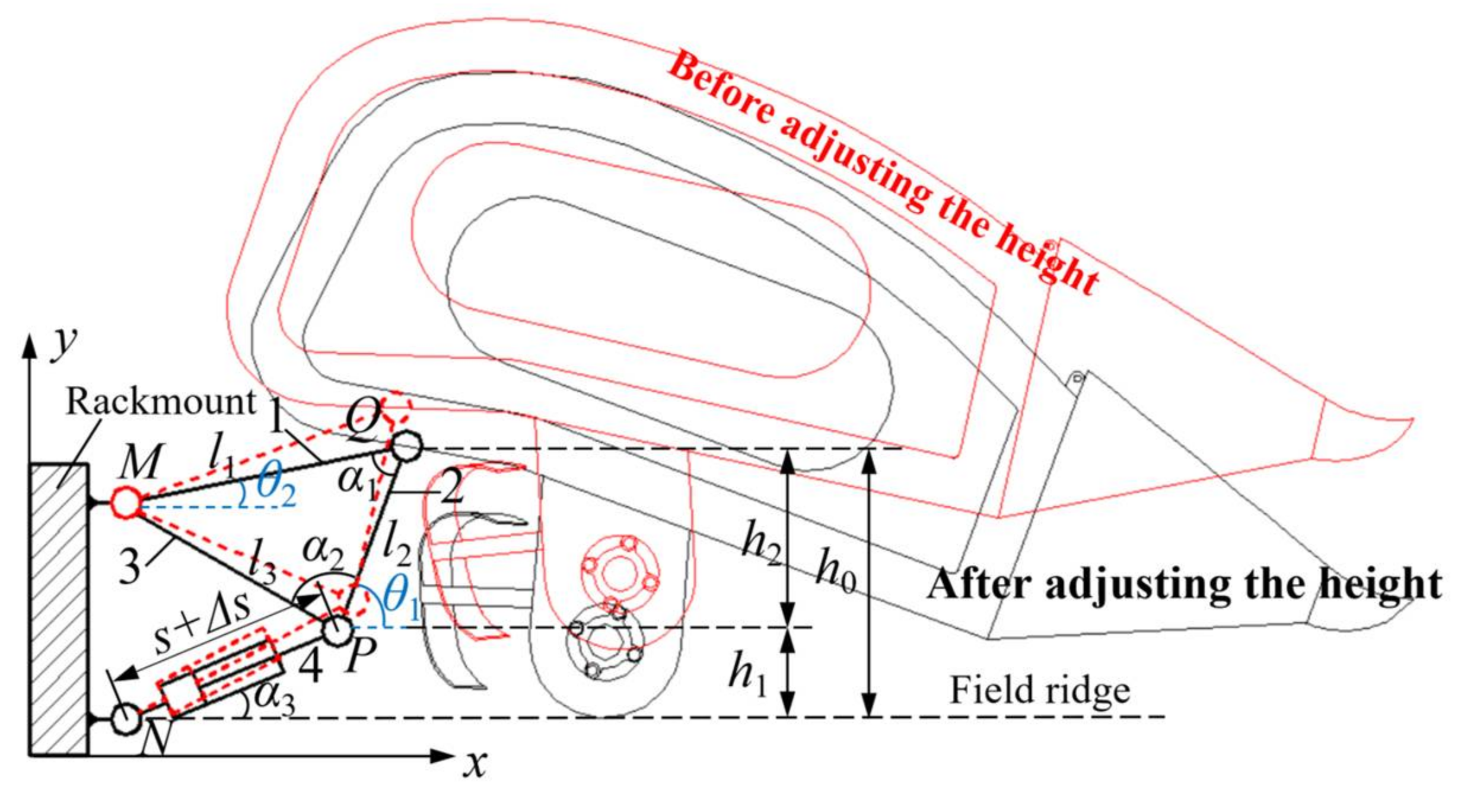
2.2.2. Design of Hydraulic Regulating Mechanism

It was necessary to analyze the movement relationship of each component in the hydraulic adjustment mechanism and find a solution to the expression of the relationship between the displacement of each hydraulic cylinder (s + Δs) and header height (h0) in order to ensure the accuracy of the automatic adjustment for maize harvester header height. On the tracked chassis frame, the two hydraulic adjustment mechanisms for the header were symmetrically located from left to right. The hydraulic cylinder served as the main mover in the unilateral mechanism, with the connecting plates for the frame upper, lower, and hydraulic cylinder acting as the follower. The mechanism has a total of five moving parts (two moving parts for each hydraulic cylinder), six rotating parts, and one movable part, giving it a freedom degree of one. Since there are as many prime movers as there are freedom degree, the mechanism moves with a clear propensity. In Figure 6, the red portion represents the situation before the header height is modified, and the black portion represents the situation following that adjustment. Both the master and the follower experience an angular change as the mechanism moves.
The x-axis was created along its horizontal direction, and the y-axis was produced perpendicular to the direction of field ridge. The positioning angles of the upper and lower connecting plates of frame were angles θ1 and θ2, respectively. The angle θ2 could be calculated using Equation (10), which was based on the positional connection between the rods inside the mechanism. From the geometric relationship depicted in Equation (11), the angle θ1 could be further deduced.
θ 2 = π α 1 + α 2 + arccos [ ( s + Δ s ) cos α 3 l 3 ]
θ 1 = θ 2 + α 1 = π α 2 + arccos [ ( s + Δ s ) cos α 3 l 3 ]
where: α1 is the angle between rod l1 and l2, α2 is the angle between rod l2 and l3, α3 is the position angle of the hydraulic cylinder.
According to Figure 5, h1 is the projected length of the active hydraulic cylinder in the y-axis, while h2 is the projected length of the connecting plate l2 under the frame in the y-axis. Equation (12) expresses the relationship between the two.
h 1 = ( s + Δ s ) sin α 3 h 2 = sin θ 1
The header height is equal to the sum of h1 and h2. Equations (11) and (12) state that h0 can be calculated using Equation (13).
h 0 = ( s + Δ s ) sin α 3 + l 2 sin α 2 + arccos [ ( s + Δ s ) cos α 3 l 3 ]
The 4YZL-2H crawler maize harvester, with a header mass of 1172 kg, was used in this investigation. Hydraulic cylinders with a capacity of 2 tons (manufactured by Shandong Hengdingsheng Hydraulic Machinery Co., Ltd. with a range of 150 mm and an initial cylinder length of 370 mm) were chosen in order to satisfy the load-bearing criteria. The hydraulic cylinder installation angle is α3 = 23° when taken into account alongside the actual size of header and the rationalization of the hydraulic adjustment mechanism installation. The frame’s upper and lower connecting plates as well as the connecting plate for the hydraulic cylinder were measured at l1 = 492 mm, l3 = 425 mm, and l2 = 341 mm, respectively. The pinch angles α1 and α2 at this moment are 58° and 80°, respectively. The final equation for the link between the displacement of the hydraulic cylinder and the header height is produced by substituting each parameter into Equation (13).
h 0 = 0.39 ( s + Δ s ) + 341 sin [ 80 ° + arccos ( s + Δ s 462 ) ]

2.3. Software Design of the Adaptive Adjustment System of Header Height

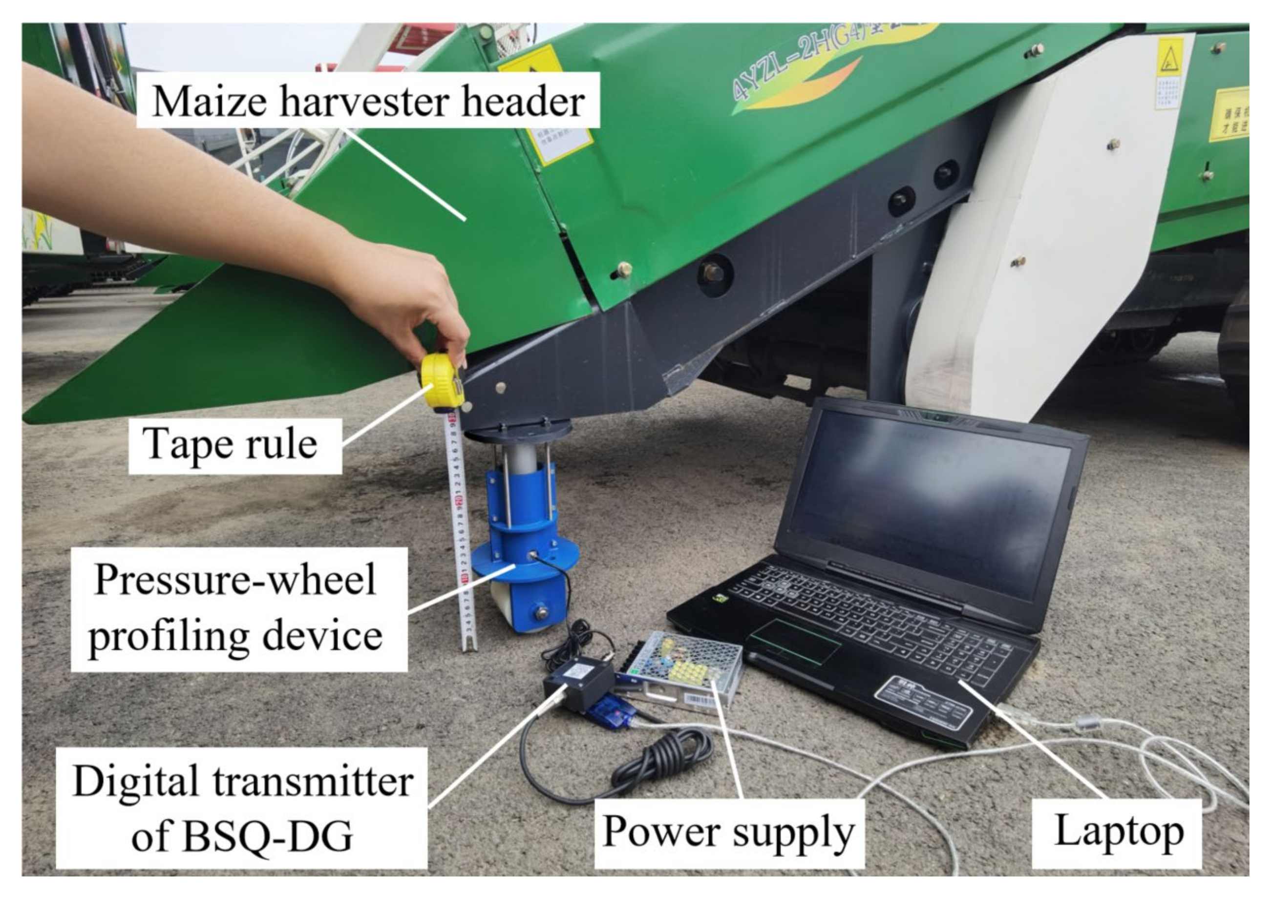
2.3.1. Calibration of Pressure-Wheel Profiling Device

When the pressure-wheel profiling device was in use, its pressure-wheel oscillated up and down in step with the terrain undulations, and the pressure regulating spring deforms. The pressure-wheel profiling device was calibrated as depicted in Figure 7 on 2 August 2022, at Changchun Jixin Agricultural Equipment Co., Ltd. (125°22′ E, 43°93′ N). The pressure-wheel was bent as a result of the header being gently pulled downward. It was evident from the calculations of the force on the profiling device discussed above that the theoretical deformation of the regulating spring was 0~23.7 mm. When the spring deflection reached 5 mm, 10 mm, 15 mm, and 20 mm, respectively, a tape measure was employed to record the information sent by the pressure sensor. After data processing and computations, it was found that the output voltage signal of pressure sensor was linear. Equation (15) illustrates the connection between the pressure value F and the output voltage U0.
F = 362.49 U 0 861.47
The test calibration was used to derive the equation relating the header height to the pressure value of the profiling device.
h 0 = 496.51 0.028 F

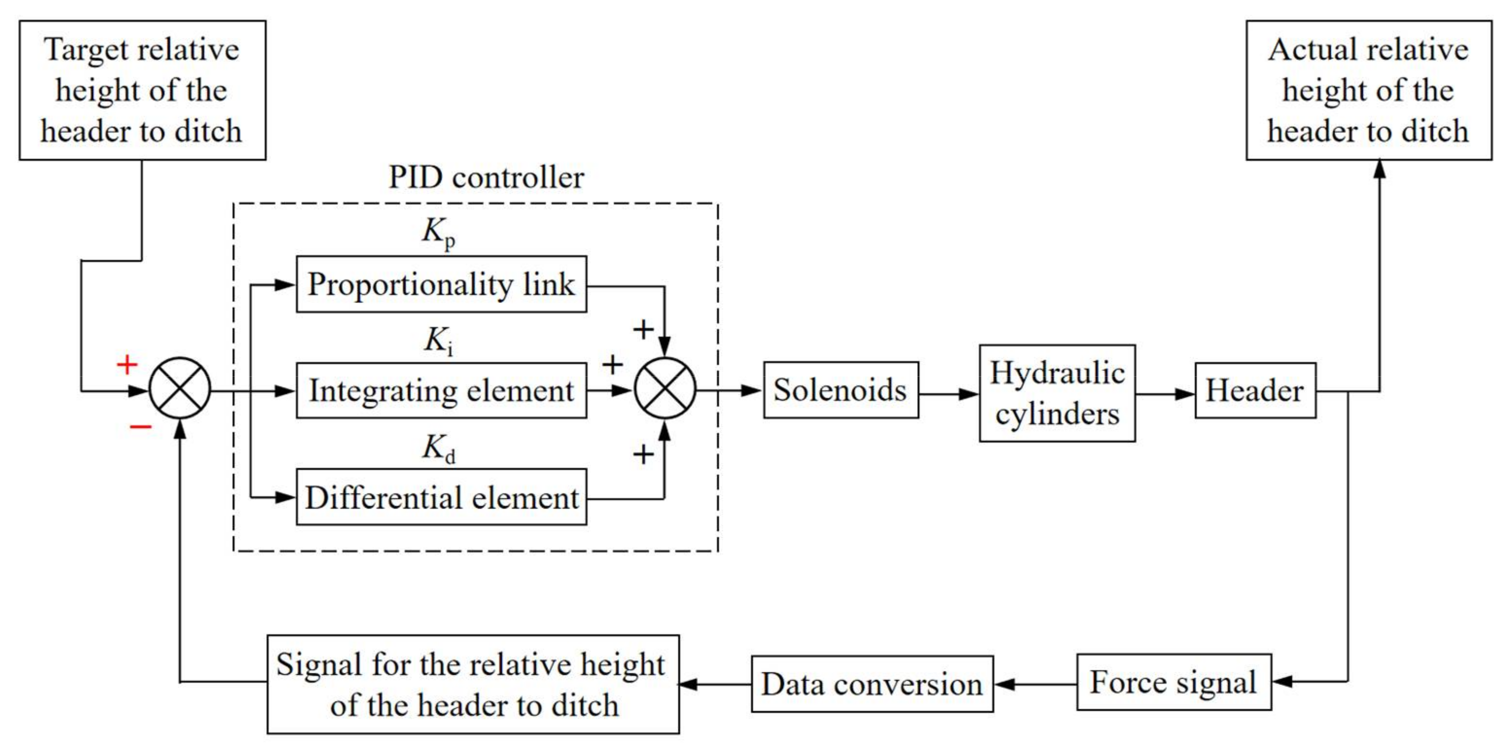
2.3.2. Control Methods for Adaptive Regulation Systems

The profiling device was used by the adaptive header height adjustment system to detect changes in the landscape relief. To determine the control deviation E(t), the set height, or the target relative header height to the field ditch, was contrasted with the feedback value of displacement sensor. The controller delivered a signal to the solenoid valve after using the PID control approach to determine the system output value. A solenoid valve managed the expansion and contraction of hydraulic cylinder as well as the header height. At this point, the force output of pressure sensor was analyzed and turned into a height signal to further determine whether the header had attained the desired relative height and enable the adaptive header height adjustment. The PID control schematic is shown in Figure 8.

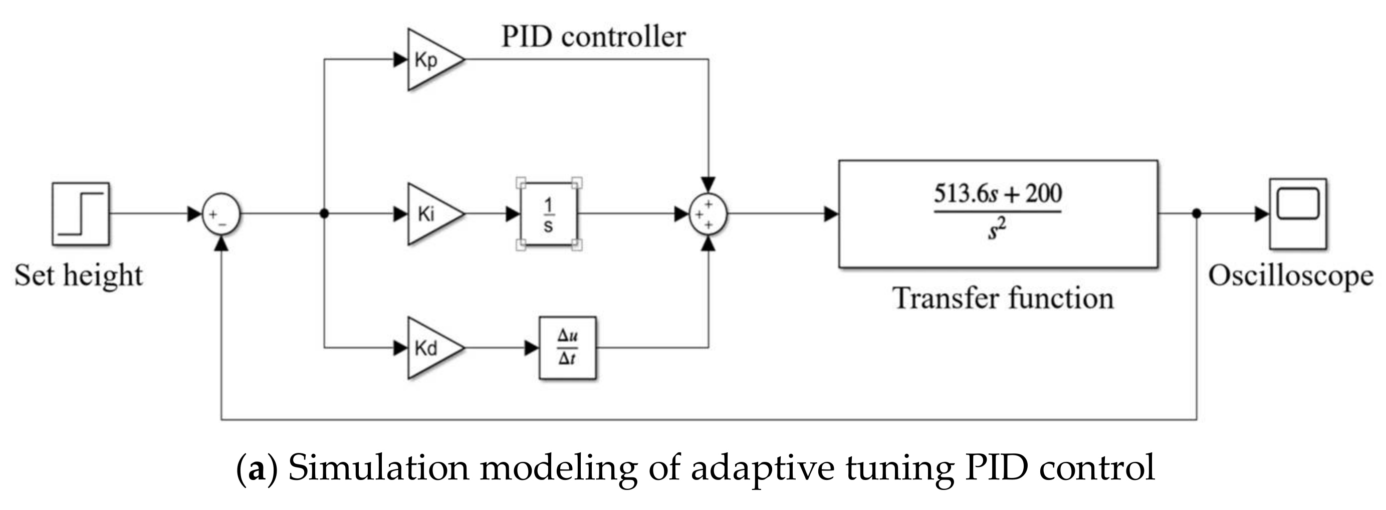
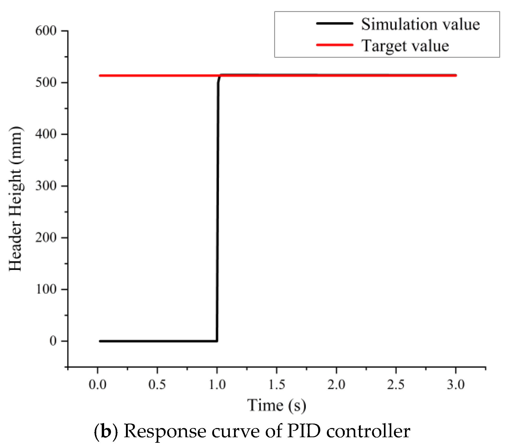
2.3.3. Simulation of Adaptive Regulation System

A simulation model was developed in the Matlab(R2021a)/Simulink software, as shown in Figure 9a, in order to further assess the viability of the control strategy, optimize the operating parameters of the adaptive adjustment system of the header height, and observe the dynamic response of the system in real time. The control system was simulated with a 3 s simulation time and a 0.01 s sampling interval. When the proportional coefficient Kp = 0.3, the integral coefficient Ki = 0.001, and the differential coefficient Kd = 4 × 10⁵, the maximum output value of PID controller was 514.9 mm, the regulation time was 0.59 s, the response overshooting percentage was 0.058%, and the steady state error was 1 mm. According to the simulation results, the system used in this study can match the design specifications for the cutter height adaptive adjustment system since it responds quickly and overshoots only little. As seen in Figure 9b, the step responses curve.

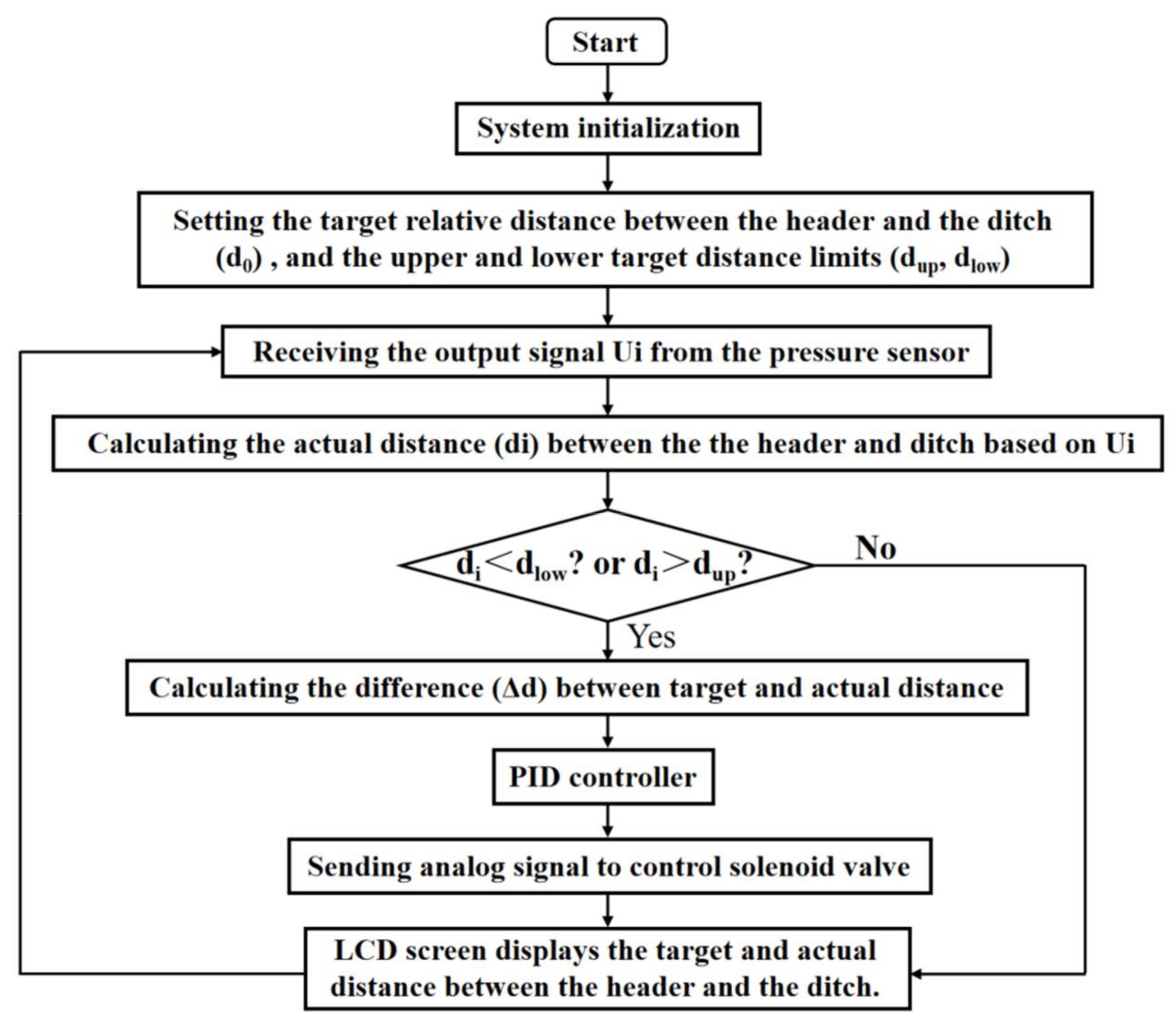
2.3.4. Programming of Adaptive Regulation Systems

In the adaptive adjustment system, the analog voltage signal (0–5 V) from the pressure sensor is used to feed back the analog current signal (4–20 mA) from the displacement sensor of the hydraulic cylinder. This signal is then filtered and processed to connect with the interface of the A/D conversion circuit. A serial communication interface is used to transmit the digitally altered analog signal to the controller. The signals that the left and right profiling devices collected must be processed by the controller. Despite the complicated field circumstances, for a given plot, the soil condition in the furrows on the left and right sides of harvester should be the same. The following conclusions are drawn about variations in ground undulation in order to prevent rapid changes in the profiling device caused by external effects. The controller will activate the hydraulic adjustment mechanism to raise or lower the header if both sides of the profiling device detect that the height has changed.
The internal system of microcontroller is initialized once the software begins to run. The upper and lower values of the goal distance are set to dup and dlow, respectively. The target relative distance between the header and the field ditch is set to be d0 (i.e., the sum of the header height h0, and ridge height). The controller receives and processes the output signal of pressure sensor, and using the processed electrical signal determines the actual distance (di) between the header and the ditch. The header height needs to be adjusted if the actual distance is outside of the target distance of upper and lower limit settings. An analog signal is supplied to regulate the solenoid valve after a PID controller determines the difference (Δd) between the goal and actual distance. The solenoid valve starts the process, and the hydraulic system is operated to adjust the header height. The operator of the harvester can observe the target and actual distance between the header and the ditch in real time via the LCD screen (Figure 10).

2.4. Field Test

2.4.1. Test Site

To verify the operational performance of the header adaptive adjustment system, the field test was conducted on 12 August 2022, at the test site of Changchun Jixin Agricultural Equipment Co. in Jilin Province (125°22′ E, 43°93′ N). This study site belonged to the continental seasonal climate, and was located at the transition from the wet zone to semi-arid zone. The experimental plot was 370 m long and 485 m wide, and its cultivation method was monopoly. The distance between the ridges was 650 mm, where the ridge width was 370 mm and the ditch width was 290 mm. Prior to seeding, the test site was plowed, and the ridges and furrows all had the same general slope. The slope undulation ranged from 14° to 21°, according to the actual measurements. “JINONGDA 823” was the name of the maize variety that was sown at the test location. Plants were spaced 230 mm apart, were 2180 mm tall on average, and had a 17.47% average moisture content in the straws. A northern black loam with a dry soil surface made up the soil at the test site. Photographs of the test site are shown in Figure 11.
All test equipment are as follows. 4YZL-2H crawler maize harvester (produced by Changchun Jixin Agricultural Equipment Co., Ltd.), Pressure-wheel profiling device, Pressure sensor (Model: JHBM-H1; Manufacturer: Bengbu Jinnuo Sensor Co., Ltd.; Country: China), Controller (Model: STM32; Manufacturer: Guangzhou Starwing Electronic Technology Co., Ltd.; Country: China), DC Power Supply (Model: VC3305; Manufacturer: Shenzhen Yisheng Shengli Technology Co., Ltd.; Country: Linyi City in China), Displacement sensor (Model: KTR-200 mm; Production company: Shenzhen Hongmai Technology Co., Ltd.; Country: China), Solenoid Valve (Model: CG24N9Z5L; Manufacturer: Beijing Huade Hydraulic Industry Group Limited Company; Country: China), Hydraulic cylinder (produced by Shandong Hengdingsheng Hydraulic Machinery Co., Ltd., with a range of 150 mm and an initial cylinder length of 370 mm; country: China), Weighing Electronic Scale, spirit level, and measuring tape.

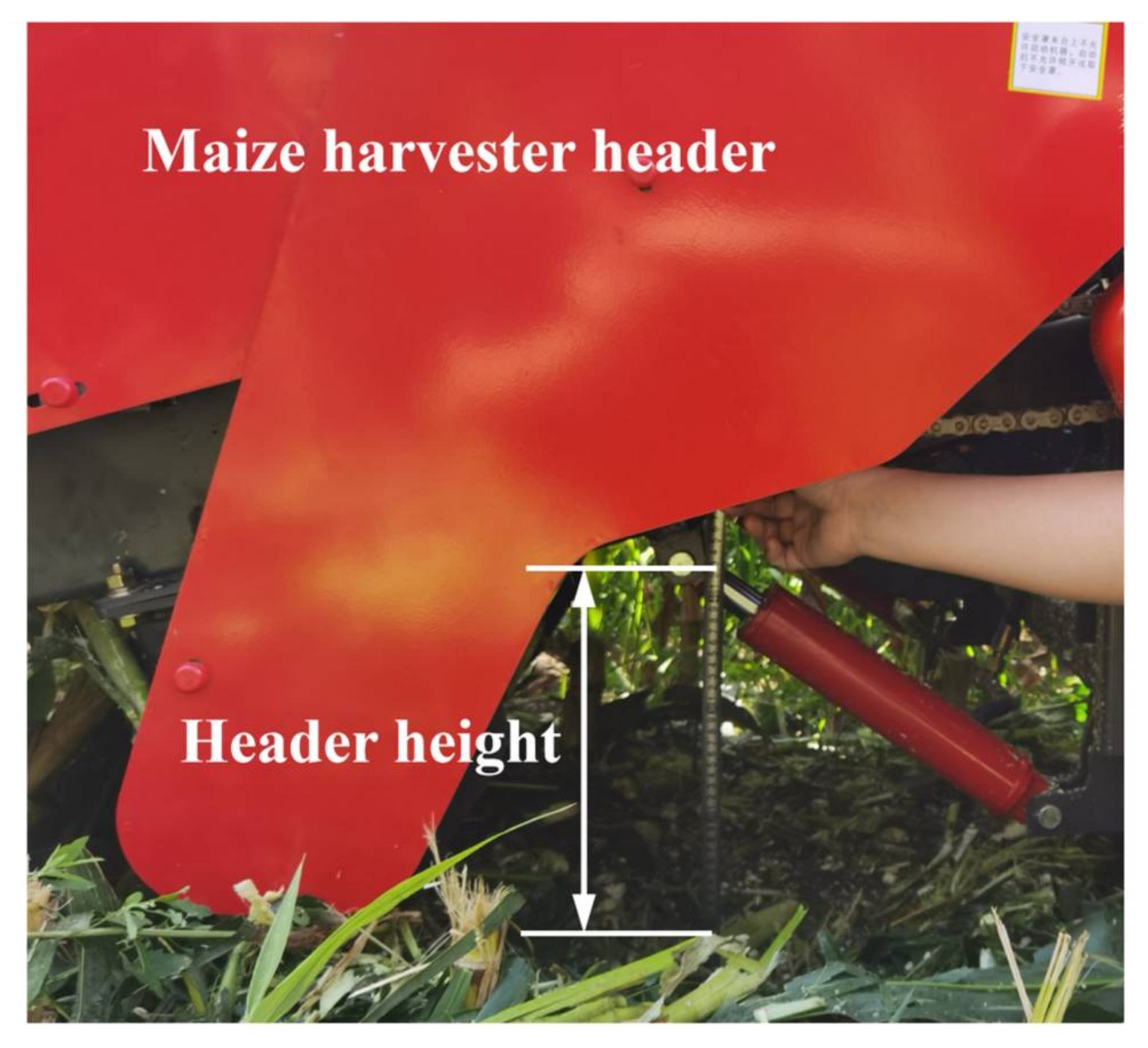
2.4.2. Verification Test of Automatic Adjustment of Header Height

A two-row equipment, the 4YZL-2H crawler maize harvester harvests two rows of maize plants simultaneously during each operation. Five test zones, each measuring 200 m in length and twice the breadth of the rows apart, were created from the test field. The test area was separated into three sections: the preparation area, measuring 5 m in length, the test area, measuring 190 m in length, and the finishing area, measuring 5 m in length. The maize harvester header was equipped with a pressure-wheel profiling device before the test, and its linear displacement sensor and pressure transducer signals had their signals calibrated. Additionally, the adaptive adjustment system of header height had been troubleshot. The operator activated the adaptive adjustment system for maize harvester header height. The system automatically adjusted the header height to 516 mm. The speed of maize harvester operating in the northeast ridge is not less than 1.2 m/s. The maximum operating speed of the 4YZL-2H crawler maize harvester in this study was 2.2 m/s. Therefore, the forward speed of harvester was selected as 1.25, 1.45, 1.65, 1.85 and 2.05 m/s in this test. In each test area, the harvester was randomly stopped after each operating distance. The testers used a measuring tape to measure the actual header height. The header height is measured as shown in Figure 12. Harvester test data were recorded separately for each speed.

2.4.3. Comparative Tests of Cob Loss Rate

At the test location, two test zones were chosen for the two operating modes of harvester—without the adaptive tuning system on and with it on. For each operation, cob quality was measured using the five-point sampling method [33,34]. Each test area contained 20 ridges whose length was 300 m. The maize harvester traveled at a speed of 1.65 m/s. After the operation of the maize harvester, a plot with an area of 1.3 m × 1.3 m was randomly selected as the measurement area, as shown in Figure 13. The diagonal lines midpoint was chosen as the center sampling point, and four places on the line that were equally spaced from the center sample point were chosen as sample points. Each of the sample points had a measurement area of 0.4 m by 0.4 m. The central sampling point was then selected from the sample point. To guarantee the accuracy of the measurements, the outcomes of 5 measurements were averaged. Harvester test data were recorded separately for each speed.
Missed and fallen cobs were gathered at the measurement area, and then they were weighed on an electronic scale. Equation (17) provides the results of the computation for the cob loss rate [35,36].
W = M 1 M 2 × 100 %
where: W is the cob loss rate, M1 is the mass of missed and fallen cobs in the measurement area, and M2 is the total mass of cobs in the measurement area.

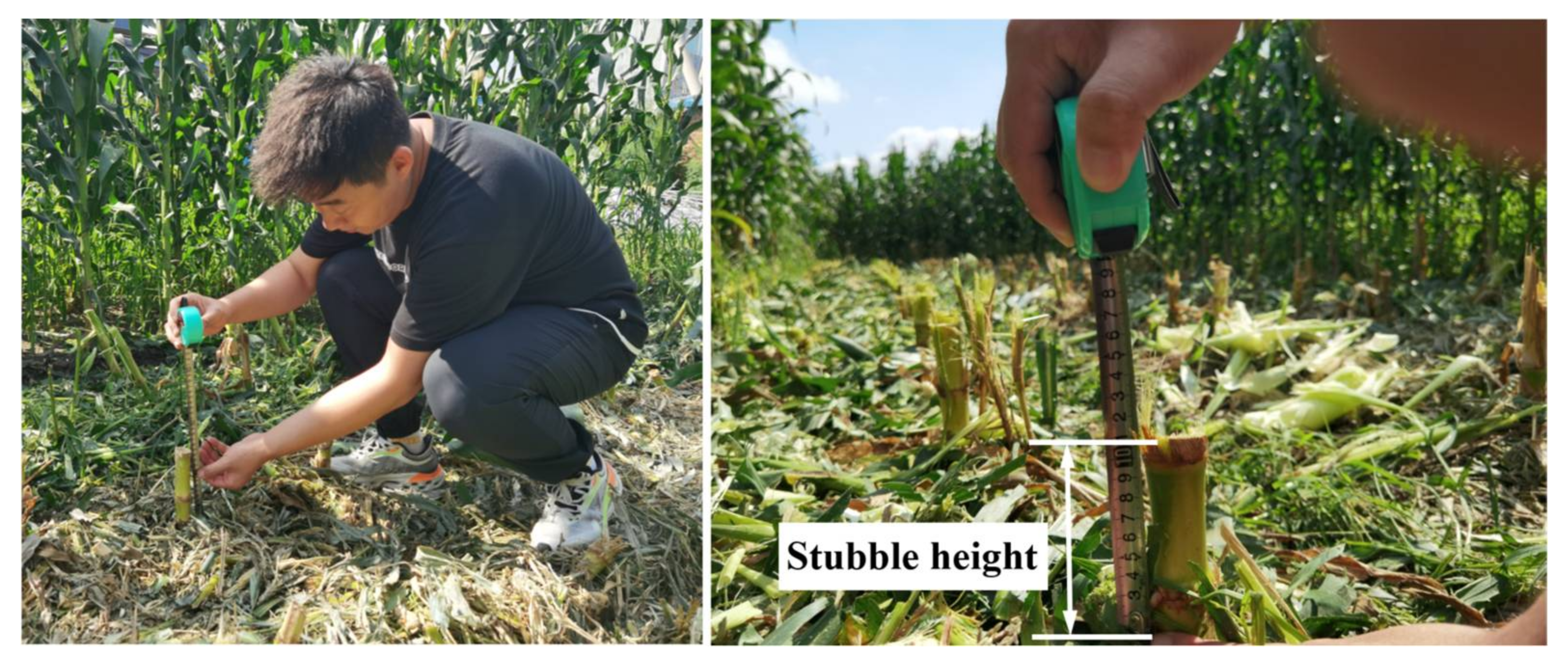
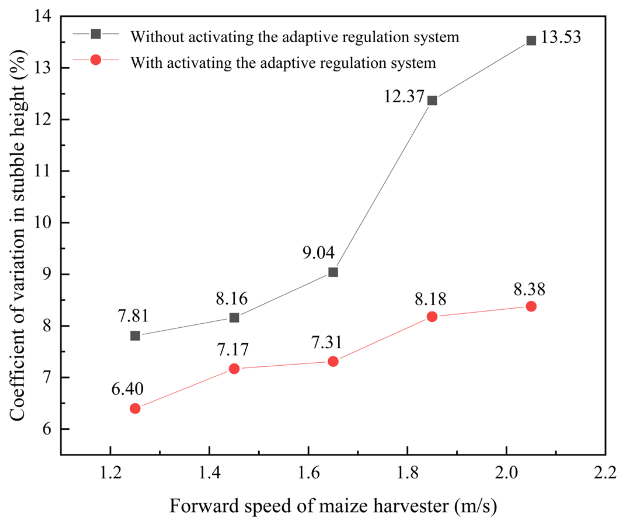
2.4.4. Comparative Tests of Coefficient of Variation for Stubble Height

The coefficient of variation in stubble height is a key indicator of the operating efficiency of the adaptive adjustment system. It is also a measurement of stability in header height operating. Two test zones were chosen at the testing location for the harvester to run in, respectively, with and without the adaptive adjustment system turned on, in order to further check the operational performance of the header height adaptive adjustment system. There were 10 ridges totaling 300 m in length in each test location. The maize harvester moved at a 1.65 m/s speed. Five rows and five measurement sites were randomly chosen in each row of each test plot at the conclusion of the harvesting process. Each measurement point was vertically measured using a measuring tape, and the distance from the ridge surface to the greatest point of stubble retention was noted, as shown in Figure 14. To guarantee the precision of the measurement, make sure the measuring tape is constantly perpendicular to the ridge surface. Harvester test data were recorded separately for each speed.
The experimental results were gathered after measuring a total of 50 points in both modes of operation. Equation (18) demonstrates the calculation of the coefficient of variation of stubble height [37].
C V = S x ¯ × 100 %
where: CV is the coefficient of variation of stubble height, is the average of stubble height, S is the standard deviation of stubble height.

3. Results and Discussion

3.1. Errors in the Automatic Adjustment of Header Height
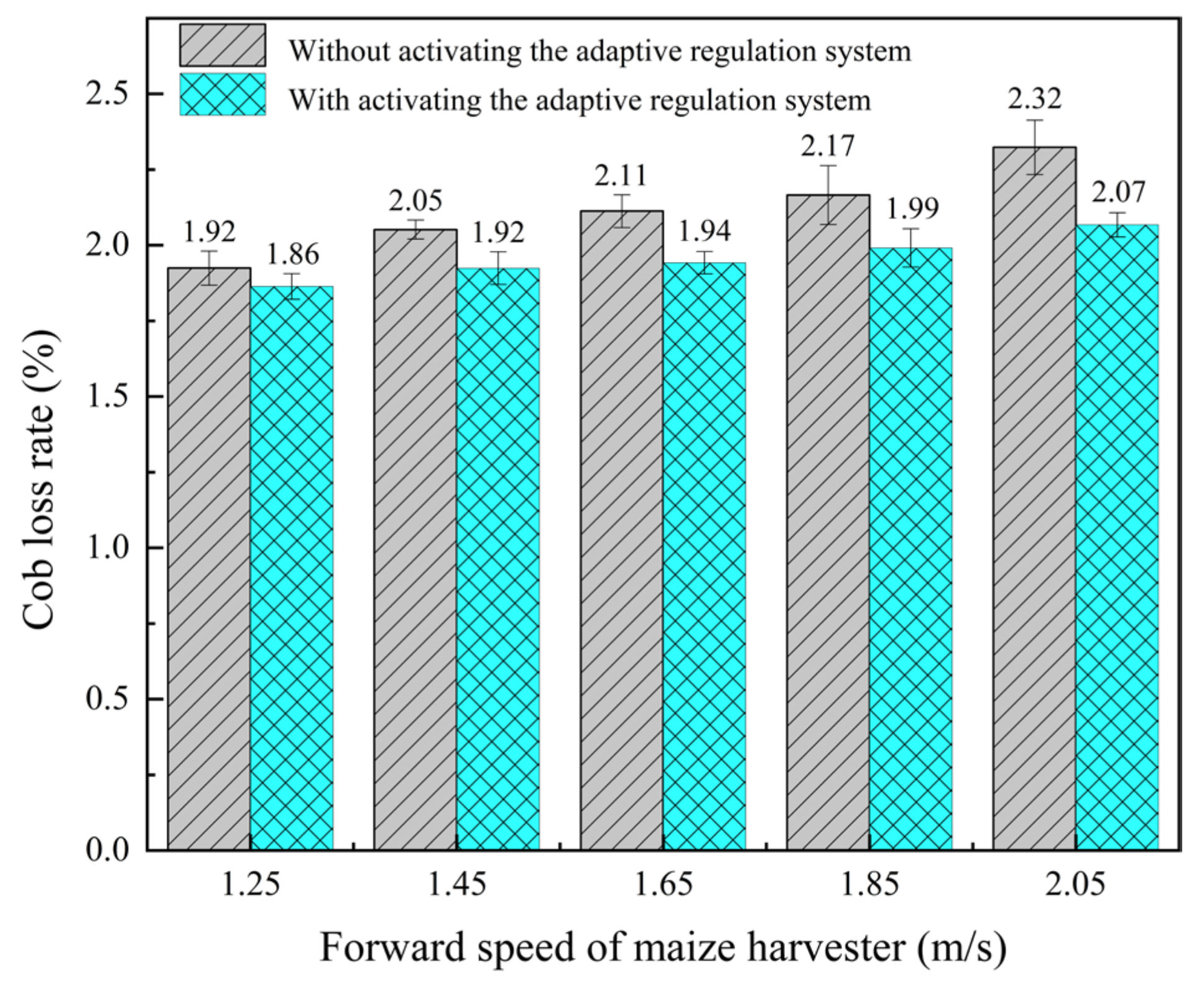
Test results of header height adjustment error at different forward speeds of maize harvester are shown in Table 3. The smallest deviation of the header height adjustment was 3 mm, and the maximum deviation was 22 mm when the results of the tests at the five forward speeds were combined, which is caused by the uneven terrain of the test location and vibration interference inside the harvester [38,39,40]. Average header height adjustment variations in the five test regions were calculated to be 7.4, 8.76, 10.22, 10.72, and 12.68 mm, in that order, with harvester operation speeds ranging from 1.25 m/s to 2.05 m/s. As forward speed increases, the average variation of header height also rises. An adaptive system is needed for the automatic adjustment of height in order to change the height of the ground in response to feedback from the profiling device. The pressure-wheel impacts from the bottom of the furrow grow as the harvester travel speed does. Increased spring vibration causes oscillations in the data acquired from the pressure sensor, which in turn causes the regulation error to grow. Furthermore, the vibration produced by the engine, debris removal fan, and straw return device inside the maize harvester operation will also affect the mechanism, leading to an adjustment error. The average deviation of header height adjustment for all test areas at all forward speeds was 9.96 mm, which is a negligibly tiny deviation value and satisfies the field operation criteria [18].

3.2. Cob Loss Rate

Comparative test results of cob loss rate under different advancing speed of maize harvester are shown in Figure 15. According to real measurements and estimates, the cob loss rate rises in both modes of operation—without the adaptive adjustment system turned on and with it on—as the harvester forward speed rises. This is due to the fact that the test site was a complex ridge-crop slope, and the greater the harvester forward speed, the greater the error in the header height adjustment (as shown by the analysis of the data in Table 2). Higher cob loss rates are caused by large operating header height changes. Compared with the operation without turning on the adaptive adjustment system, the maize harvester with the adaptive adjustment system reduced the cob loss rate by 3.23%, 6.77%, 8.76%, 9.05%, and 12.08% for the five forward speed modes, in that order. From the data, the greater the harvester forward speed, the more effective the system works. Without an adaptive adjustment system, the operator must manually adjust the header height, which results in a significant cob loss rate due to the height adjustment inaccuracy. When the adaptive adjustment system is on, the system continuously monitors and adjusts header height using its hydraulic adjustment mechanism. The header height is regulated in real time and more maize cobs enter the scope of harvester operation, which lowers the cob loss rate. The maximum value of cob loss rate after maize harvester operation was 2.37% and less than 2.5% in the system regulation mode, which complies with the national technical standard GB/T 34373-2017 [41], “maize Harvester—Cob Picking and Header”.

3.3. Coefficient of Variation in Stubble Height

Comparative test results of coefficient of variation in stubble height under different advancing speed of maize harvester are shown in Figure 16. Based on the test data, it is clear that in all operating modes without activating the adaptive adjustment system, the coefficient of variation in stubble height rises as forward speed increases. After a forward speed of 1.65 m/s, the coefficient of variation in stubble height accelerated. The coefficient of variation in stubble height decreased for each of the five forward speed modes after activating the adaptive adjustment system by 22.03%, 13.81%, 23.67%, 51.22%, and 61.46%, in that sequence. When the harvester forward speed is at its highest, the system performs at its best. This is as a result of the adaptive adjustment system of header height, which can provide real-time monitoring of monopoly platform height changes and timely management of the hydraulic adjustment mechanism to modify the header height. The distance between the center of the moveable knife roller of the straw returning device and the ridge platform is also steady when the operational header height is kept constant, which lowers the error of the height of the straw stubble. Without an adaptive adjustment system, the operator is limited to manually adjusting the header height as the terrain changes. Because of the significant adjustment error, the variance coefficient of stubble height has increased.

4. Conclusions

A header height adaptive adjustment system based on a 4YZL-2H crawler maize harvester was built to address the issue of low automation of header height adjustment of maize harvesters in ridges of Northeast China. The pressure-wheel profiling device, which gives real-time input on terrain change, is used to control the system while a person is walking on the ridge and furrow surface. Automatic adjustment is achieved by the STM32 control unit receiving and processing the terrain change signals in real-time before controlling the hydraulic adjustment mechanism to change the header height.
A force analysis of the pressure-wheel profiling device was performed in the adaptive adjustment system hardware to determine the structural dimensions and operational parameters of its major components. The pressure-wheel had a diameter of 110 mm and a breadth of 100 mm, respectively. The middle diameter, coil count, wire diameter of regulating spring and stiffness coefficient were each 37.8 mm, 11 mm, 2.2 mm, and 49.34 N/mm, respectively. Theoretically, the controlling spring might have morphologies ranging from 0 to 23.7 mm. A kinematic analysis of the hydraulic regulating mechanism was performed to generate an expression for the mathematical link between the hydraulic cylinder displacement (s + Δs) and the cutting table height (h0). A PID control method was developed, system simulation in Matlab/Simulink software was performed, the operating parameters of the adaptive regulation system were optimized, and system programming was completed.
The forward speed of maize harvester and the working mode of the adaptive adjustment system were taken as test factors. The header height adjustment error, cob loss rate and coefficient of variation in stubble height were taken as test indexes. Field test trials were conducted. Test data with and without the adaptive tuning system on were analyzed and compared for five forward speeds. The findings revealed that, with the adaptive adjustment system mode on, the average difference between the measured actual header height and the predetermined height was 9.96 mm, which improves the performance of header height automatic adjustment. The average coefficient of variation in stubble height was lowered by 34.44%, which can effectively improve the maize harvesting quality and enhance the adaptability of header to fallen corn. In addition, the average cob loss rate was decreased by 7.98%, both of which may accommodate the needs of maize harvester header height adjustment.
Although header height adaptive adjustment system in this study aids in the automation of maize harvesters for ridged crops in Northeast China, it also has several flaws. When the harvester forward speed hits 2.05 m/s, the pressure regulating spring of the profile device vibrates more, causing irregularities in the acquisition of the pressure sensor signal. The cob loss rate and coefficient of variation in stubble height are impacted, and the header height adjustment error rises as a result. Our team will investigate how the harvester forward speed and pressure-wheel profiling device work through following research, and will also further optimize the operational parameters of regulating spring. At the same time, the team will also explore the relationship between the movement state of corn stalks between pick sticks and the structure and movement parameters of ear picking, to further optimize the operating parameters of the height adaptive adjustment system. Finally, test research on the effectiveness of the header height adaptive adjustment system in this paper only uses one model. The team will investigate the system operational performance on several harvester model types in forthcoming research to assess the system generalizability.

Author Contributions

Conceptualization, H.T. and G.W.; methodology, H.T. and G.W.; software, S.Z., H.J., M.X. and X.G.; validation, S.Z., H.J. and Z.Z. (Zihao Zhou); formal analysis, M.Q., Z.Z. (Zhaobo Zou) and H.L.; investigation, M.Q.; resources, M.X. and M.Q.; data curation, H.J. and S.Z.; writing—original draft preparation, H.T. and G.W.; writing—review and editing, H.T. and G.W.; visualization, H.T., S.Z. and H.J.; supervision, M.Q. and Z.Z. (Zhaobo Zou); project administration, G.W. and H.J.; funding acquisition, G.W. and H.J. All authors have read and agreed to the published version of the manuscript.

Funding

This research was funded by the National Key R & D Program of China (grant number: 2022YFD1500701), and the Science and Technology Development Project of Jilin Province (grant number: 20210202019NC, 20220203081SF).

Institutional Review Board Statement

Not applicable.

Informed Consent Statement

Not applicable.

Data Availability Statement

Not applicable.

Acknowledgments

We highly appreciate Changchun Jixin Agricultural Equipment Co., Ltd. for providing the test site.

Conflicts of Interest

The authors declare no conflict of interest.

References

  1. Lin, J.; Yang, M.; Zhang, X.; Liu, P.; Li, S.; Peng, J. Evaluation of Wheat and Corn Harvester Selection in Hilly and Mountainous Area. Trans. CSAM 2022, 53, 150–157. [Google Scholar]
  2. Zhang, Z.; Li, S.; Han, Z.; Bai, X.; Li, T.; Zhang, B. Design and Test of a New Type Header of Corn Harvester for Reaping Both Corn Stalk and Spike. In Proceedings of the 2017 ASABE Annual International Meeting, Spokane, WA, USA, 16–19 July 2017; p. 1701395. [Google Scholar]
  3. Li, Z.; Jianqun, Y.; Qiang, Z.; Chuanxin, L.; Xvwen, F. Design and Experimental Study of Bionic Reverse Picking Header for Fresh Corn. Agriculture 2022, 13, 93. [Google Scholar]
  4. Nigon, B.J.; Shinners, K.J.; Cook, D.E. Harvester Modifications to Alter Composition and Dry Matter of Corn-Silage. Appl. Eng. Agric. 2016, 32, 157–167. [Google Scholar]
  5. Tao, C.; Fan, C.; Zhang, D.; Li, Y.; LI, Y.; Zhao, H. Research Progress of Maize Mechanized Harvesting Technology. Trans. CSAM 2019, 50, 1–13. [Google Scholar]
  6. Xu, H. Research on Intelligent Control Design of Sugarcane Harvest; Guangxi University of Science and Technology: Liuzhou, China, 2022. [Google Scholar]
  7. Liu, H. Research on Structural Optimization and Control Strategies for Adaptive Wheat Cutting Tables; Shandong University of Technology: Zibo, China, 2022. [Google Scholar]
  8. Liu, Y. Design and Experiment of Wide Folding Rape Windrower Based on Crawler Type Power Chassis; Huazhong Agricultural University: Wuhan, China, 2022. [Google Scholar]
  9. Long, Z.; Xiang, Y.; Li, Y.; Hu, Z.; Liu, A.; Dai, X. Adaptive Adjustment System of Header Height Based on Inclination Sensor. J. China Agric. Univ. 2021, 26, 200–208. [Google Scholar]
  10. Song, Y. Design and Test of Adaptive Adjustment System for Combine Harvester Header Height; Huazhong Agricultural University: Wuhan, China, 2022. [Google Scholar]
  11. Liu, G.; Ni, Y.; Yang, T.; Qi, Y.; Jin, C. Design and Experiment of Header Height Automatic Control System for Soybean Harvester. J. Chin. Agric. Mech. 2023, 44, 155–160. [Google Scholar]
  12. Sun, Y.; Xu, L.; Jing, B.; Chai, X.; Li, Y. Development of A Four-point Adjustable Lifting Crawler Chassis and Experiments in A Combine Harvester. Comput. Electron. Agric. 2020, 173, 105416. [Google Scholar] [CrossRef]
  13. Zhang, Z. Design and Analysis of Hydraulic Lifting System of Combine Harvester Cutting Table; Shandong University of Science and Technology: Qingdao, China, 2019. [Google Scholar]
  14. Zhang, C. Research on Header Profiling and Crop Height Measurement Method; Southeast University: Nanjing, China, 2019. [Google Scholar]
  15. Liao, Y.; Xiang, Y.; Wu, M.; Liu, D.; Cheng, Y.; Li, Y. Design and Test of the Adaptive Height Adjustment System for Header of the Combine–Harvester. J. Hunan Agric. Univ. 2018, 44, 326–329. [Google Scholar]
  16. Ni, Y.; Jin, C.; Chen, M.; Yuan, W.; Qian, Z. Computational Model and Adjustment System of Header Height of Soybean Harvesters Based on Soil-machine System. Comput. Electron. Agric. 2021, 183, 105907. [Google Scholar] [CrossRef]
  17. Jin, C.; Liu, G.; Ni, Y.; Yang, T.; Wang, T.; Qi, Y. Design and Experiment of Header Profiling Mechanism for Combine Harvester Based on MBD-DEM Coupling. Trans. CSAE 2022, 38, 1–10. [Google Scholar]
  18. Geng, A.; Zhang, M.; Zhang, J.; Zhang, Z.; Gao, A.; Zheng, J. Design and Experiment of Automatic Control System for Corn Header Height. Trans. CSAM 2020, 51, 118–125. [Google Scholar]
  19. Gong, Y.; Jin, Z.; Bai, X.; Wang, S.; Wu, L.; Huang, W. Design and Experiment of Servo Control System for Sugarcane Header. Trans. CSAM 2023, 54, 119–128. [Google Scholar]
  20. Luo, N.; Meng, Q.; Feng, P.F.; Qu, Z.; Yu, Y.; Liu, D.; Müller, C.; Wang, P. China can be self-sufficient in maize production by 2030 with optimal crop management. Nat. Commun. 2023, 14, 2637. [Google Scholar] [CrossRef] [PubMed]
  21. Zhuang, X.; Li, Y. Header Height Control Strategy of Harvester Based on Robust Feedback Linearization. Trans. CSAM 2020, 51, 123–130. [Google Scholar]
  22. Zhou, D.; Jin, C.; Ni, Y.; Zhang, G. Design and test on fuzzy control system for height of combine harvester header. Jiangsu Agric. Sci. 2019, 47, 264–267. [Google Scholar]
  23. Tian, W. Research and Implementation of Ultrasonic Distance Measurement System; Nanjing University of Posts and Telecommunications: Nangjing, China, 2017. [Google Scholar]
  24. Ji, K.; Li, Y.; Li, G.; Wang, X.; Wang, H. Design and Test of Height Auto-control Device of Combine Header. J. Agric. Mech. Res. 2023, 45, 85–89, 94. [Google Scholar]
  25. Li, J.; Huang, H.; Wang, Y.; Tian, L.; Ren, L. Development on Research of Soft-terrain Machine Systems. Trans. CSAM 2015, 46, 306–320. [Google Scholar]
  26. Zhai, G. Research on Dynamics of Combined Contact Mode of Wheel-Ground on Planetary Rovers; Beijing Jiaotong University: Beijing, Chiina, 2020. [Google Scholar]
  27. Zhang, J.; Yang, C.; Zhang, L.; Jiang, Y.; Wang, C. Analysis and experiment on strength and vibration characteristics of corn stubble plucking mechanism. Trans. CSAE 2018, 34, 72–78. [Google Scholar]
  28. Zhao, S.; Tan, H.; Wang, J.; Yang, C.; Yang, Y. Design and experiment of multifunctional integrated seeding opener. Trans. CSAE 2018, 34, 58–67. [Google Scholar]
  29. Tong, J.; Zhang, Z.; Chen, D.; Zhang, Q.; Ma, Y. Three-dimensional dynamic finite element analysis of interaction between toothed wheel and soil. Trans. CSAE 2014, 30, 48–58. [Google Scholar]
  30. Tong, J.; Zhang, Q.; Chang, Y.; Li, M.; Zhang, L.; Liu, X. Finite Element Analysis and Experimental Verification of Bionic Press Roller in Reducing Adhesion and Resistance. Trans. CSAM 2014, 45, 85–92. [Google Scholar]
  31. Liu, H.; Zhao, S.; Tan, H.; Yang, Y.; Zhang, X. Investigation on Press Device in Reducing Adhesion and Resistance Based on Scrape and Vibration Principle. Trans. CSAM 2018, 49, 86–92. [Google Scholar]
  32. Tong, J.; Zhang, Q.; Chang, Y.; Chen, D.; Dong, W.; Zhang, L. Reduction of Soil Adhesion and Traction Resistance of Ridged Bionic Press Rollers. Trans. CSAM 2014, 45, 135–140. [Google Scholar]
  33. Jia, H.; Tan, H.; Ma, Z.; Zhou, S.; Wang, G. Design and experiment of the straw breaking and diversion device for maize harvesters. Trans. CSAM 2022, 38, 12–23. [Google Scholar]
  34. Li, Y.; Guo, C.; Yao, D.; He, N.; Zhang, X.; Wu, Z.; Li, Y. Design and experiment of banana straw crushing and returning machine with anti-wrapping device supported by flailing blade. Trans. CSAE 2021, 37, 11–19. [Google Scholar]
  35. Geng, D.; Sun, Y.; Li, H.; Mou, X.; Zhang, G.; Wang, Z.; Lu, X. Design and experiment of crawler corn harvester for sloping fields. Trans. CSAE 2021, 37, 11–19. [Google Scholar]
  36. Tang, Z.; Liu, S.; Zhou, F.; Li, T.; Wang, J.; Li, C. Design and Experiment of Ear Harvester for Seed Corn. Trans. CSAM 2021, 52, 102–112. [Google Scholar]
  37. Zhang, Z.; He, J.; Li, H.; Wang, Q.; Ju, J.; Yan, X. Design and Experiment on Straw Chopper Cum Spreader with Adjustable Spreading Device. Trans. CSAM 2017, 48, 76–87. [Google Scholar]
  38. Pang, J.; Li, Y.M.; Ji, J.T.; Xu, L.Z. Vibration excitation identification and control of the cutter of a combine harvester using triaxial accelerometers and partial coherence sorting. Biosyst. Eng. 2019, 185, 25–34. [Google Scholar] [CrossRef]
  39. Yao, Y.; Song, Z.; Du, Y.; Zhao, X.; Mao, E.; Liu, F. Analysis of vibration characteristics and its major influenced factors of header for corn combine harvesting machine. Trans. CSAE 2017, 33, 40–49. [Google Scholar]
  40. Lai, X.; He, G.; Li, S.; Zeng, B.; Mo, H.; Teng, X.; Cao, B. Experimental research on the axial vibration of the cutting system for sugarcane harvesters. Trans. CSAE 2021, 37, 12–20. [Google Scholar]
  41. GB/T 34373-2017; Corn Harvest Machine—Picking Header. General Administration of Quality Supervision, Inspection and Quarantine: Beijing, China, 2017.
Figure 1. Structure diagram of adaptive adjustment system of header height of maize harvester. (1) maize harvester header, (2) STM32 control unit and key module, (3) Hydraulic adjustment system, (4) Pressure-wheel profiling device.
Sustainability 15 14137 g001
Figure 2. Adaptive adjustment system for the header height.
Sustainability 15 14137 g002
Figure 3. Working Principle of adaptive adjustment system for header height.
Sustainability 15 14137 g003
Figure 4. Structure diagram of pressure-wheel profiling device. (1) Pressured plate, (2) Connecting rod, (3) Regulating spring, (4) Pressure sensor, (5) Left shell plate, (6) Connecting shaft, (7) Pressure-wheel, (8) Right shell plate, (9) Spring pallet.
Sustainability 15 14137 g004
Figure 5. Schematic diagram of force analysis of pressure-wheel profiling device.
Sustainability 15 14137 g005
Figure 6. Schematic diagram for kinematic analysis of hydraulic mechanisms. (1) Connecting plate for the frame upper, (2) Connecting plate for the frame lower, (3) Connecting plate for hydraulic cylinders, (4) Hydraulic cylinders.
Sustainability 15 14137 g006
Figure 7. Calibration of pressure-wheel profiling device.
Sustainability 15 14137 g007
Figure 8. Schematic diagram of PID control for header height adaptive adjustment.
Sustainability 15 14137 g008
Figure 9. Simulation of Adaptive Regulation System.
Sustainability 15 14137 g009aSustainability 15 14137 g009b
Figure 10. Flowchart of the adaptive regulation system.
Sustainability 15 14137 g010
Figure 11. Field test site.
Sustainability 15 14137 g011
Figure 12. Measurement of header height.
Sustainability 15 14137 g012
Figure 13. Measurement of cob loss rate.
Sustainability 15 14137 g013
Figure 14. Measurement of coefficient of variation for stubble height.
Sustainability 15 14137 g014
Figure 15. Comparative test results of cob loss rate under different advancing speeds.
Sustainability 15 14137 g015
Figure 16. Comparative test results of coefficient of variation in stubble height under different advancing speeds.
Sustainability 15 14137 g016
Table 1. Soil physical and chemical properties.
TargetsValue
(Depth 0~100 mm) Average soil moisture content/%16.49
(Depth 0~50 mm) Average soil firmness/kPa126.7
(Depth 0~50 mm) Soil capacity/(g·cm−3)1.17
Soil composition/%12.68 (Viscous particles), 64.15 (Powder particles), 23.17 (Sand particles)
PH-value7.04
Organic matter content/%2.53
Table 2. Instrument technical details.
InstrumentTypeManufacturerRangeAccuracy
MicrocontrollerSTM32F4072GGuangzhou Starwing Electronic Technology Co., Ltd., Guangzhou City, Guangdong Province, China//
Pressure SensorJHBM-H1Bengbu Jinnuo Sensor Co., Ltd., Bengbu, Anhui Province, China0~3000 N±10 N
Solenoid-directed valve4WE6F61B/CG24N9Z5LBeijing Huade Hydraulic Industry Group Limited Liability Company, Beijing, China0~31.5 Mpa0.1 Mpa
Displacement SensorKTR-200Shenzhen Hongmai Technology Co., Ltd., Shenzhen, China0~200 mm0.01 mm
Hydraulic cylinder40-25-150Shandong Hengdingsheng Hydraulic Machinery Co., Ltd., Linyi City, Shandong Province, China0~150 mm/
Table 3. Test results of header height adjustment error at different forward speeds of maize harvester.
Test AreaTest NumberSetting Header Height/mmDifferent Forward Speeds of Maize Harvester (m/s)
1.251.451.651.852.05
Measured Value/mmDeviation/mmMeasured Value/mmDeviation/mmMeasured Value/mmDeviation/mmMeasured Value/mmDeviation/mmMeasured Value/mmDeviation/mm
11516520450795226522649521
2516509752155193519350917
35165261050313501155011552711
45165106507952913529135088
551650795248507950795204
215165088528125088508850610
251651065226525952595259
351652265079527115271150016
451650795193498184981850412
5516521550511505115051149719
315165041250313524852485215
251651155215500165001649521
351652375133503135031350313
4516510649917521552155248
5516509750795079507950511
41516522651155248524852610
251650511528125106510650610
351650975097505115051149521
45165261052711529135291352913
5516512450610512451245079
51516523752595259525949422
2516507951155248524852711
35165061049917506105061050313
451651335088513351335248
5516505115133497194971950115
Disclaimer/Publisher’s Note: The statements, opinions and data contained in all publications are solely those of the individual author(s) and contributor(s) and not of MDPI and/or the editor(s). MDPI and/or the editor(s) disclaim responsibility for any injury to people or property resulting from any ideas, methods, instructions or products referred to in the content.

