
Efficient Production of Doughnut-Shaped Ce:Nd:YAG Solar Laser Beam
 ,
,  , , , ,
  , and
, and
Abstract
:1. Introduction
2. Materials and Methods
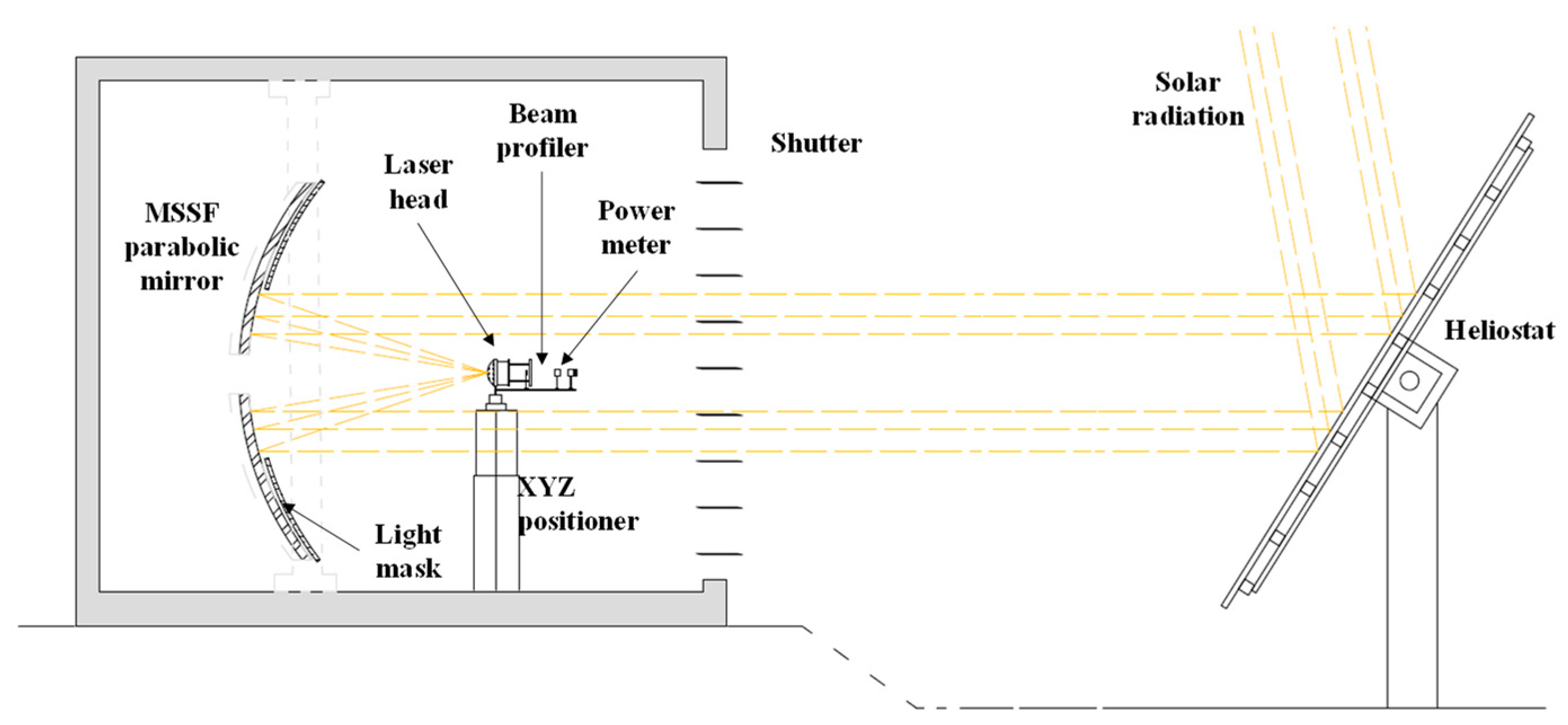
2.1. Solar Energy Collection and Concentration: MSSF Heliostat-Parabolic System
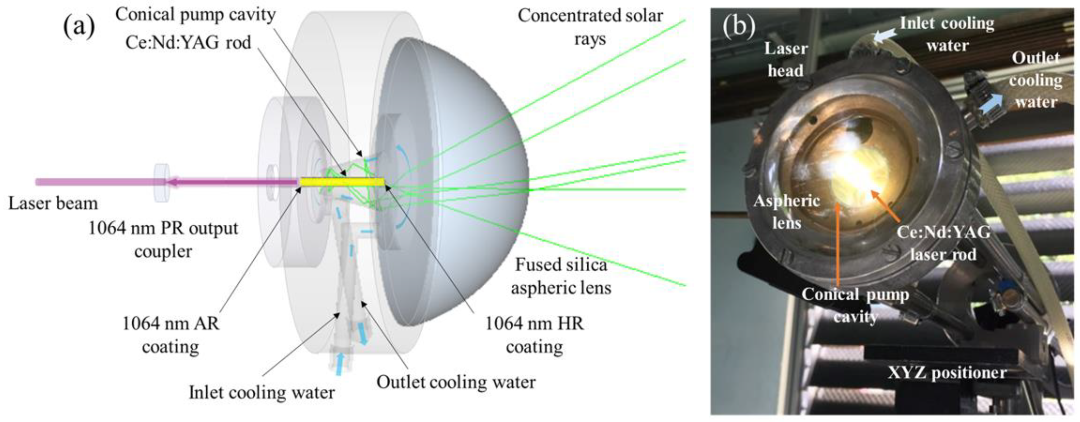
2.2. End-Side Pumped Solar Laser Head
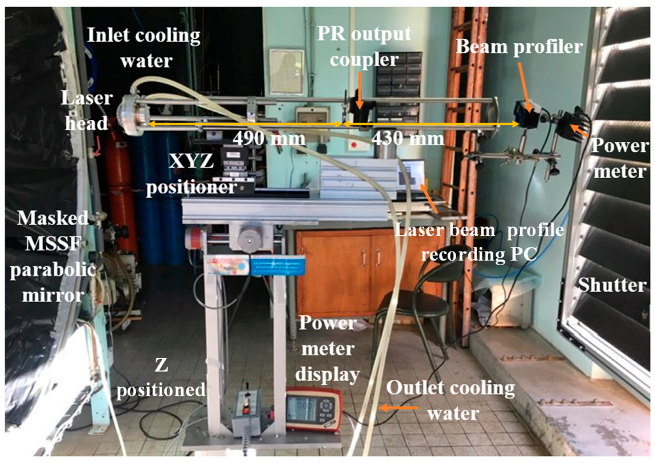
2.3. Resonant Cavity and Beam Profile Setup
3. Measurements and Results
3.1. Ce:Nd:YAG End-Side-Pumped Solar Laser Experiment during the Cloudless Sky Period
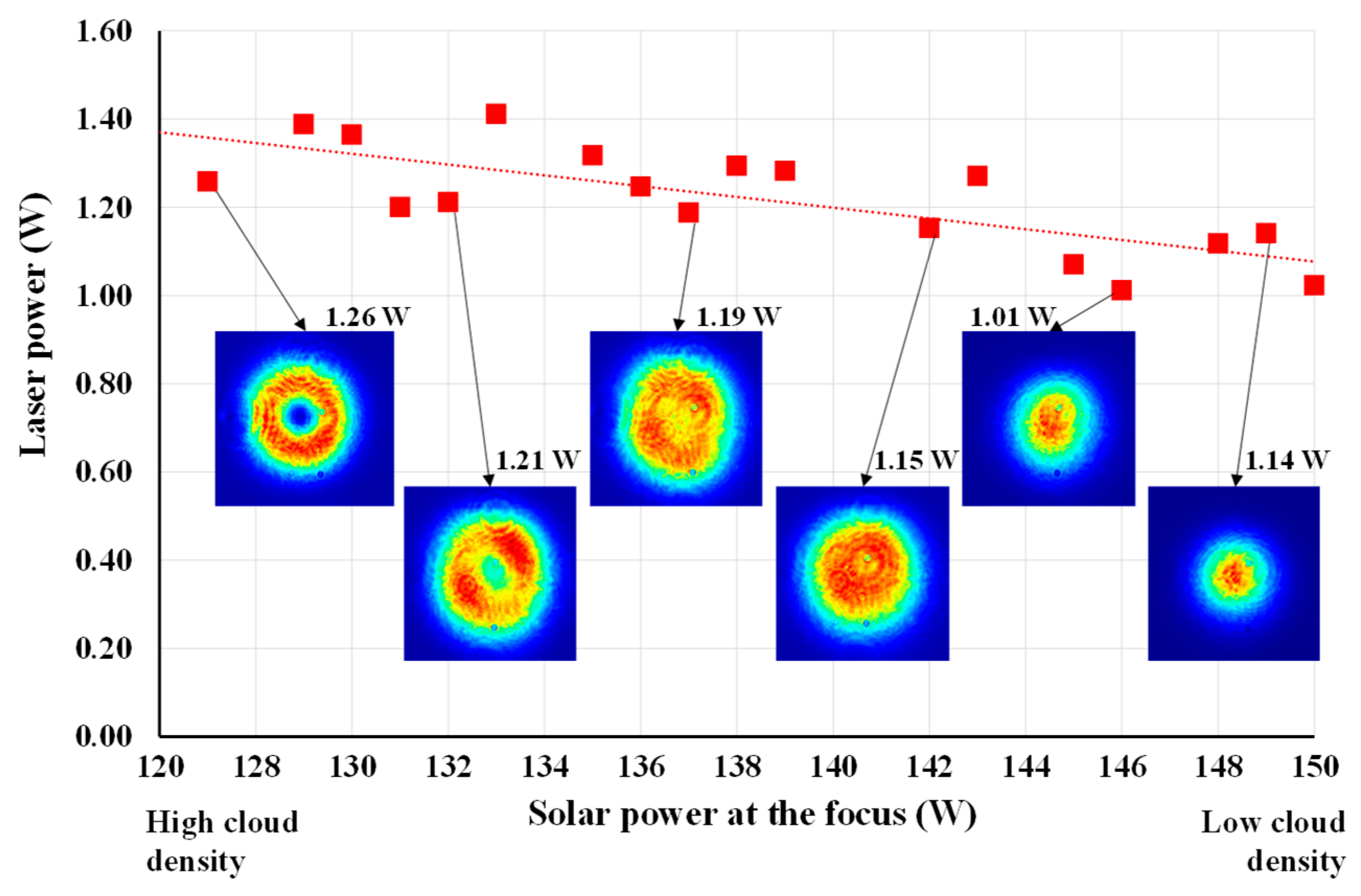
3.2. Ce:Nd:YAG End-Side-Pumped Solar Laser Experiment during a Thin Layer of Clouds
3.3. Solar Laser Beam in Cloudy Sky Conditions
4. Discussions
4.1. Solar Laser Power Emission during Clear and Cloudy Weather
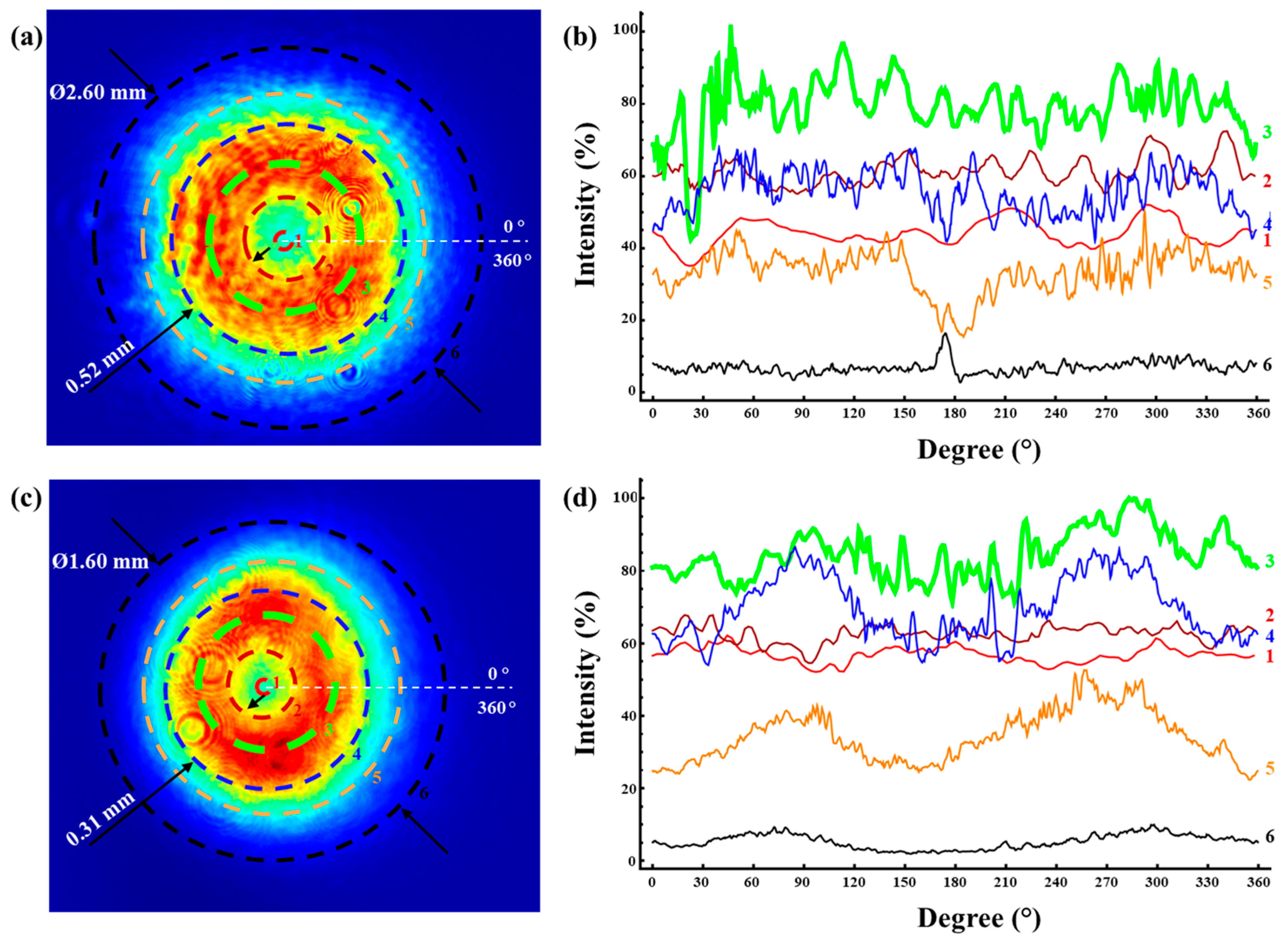
4.2. Rotational Symmetry and Depletion Depth of the Doughnut-Shape Beam
5. Conclusions
Author Contributions
Funding
Institutional Review Board Statement
Informed Consent Statement
Data Availability Statement
Acknowledgments
Conflicts of Interest
References
- Lando, M.; Kagan, J.A.; Shimony, Y.; Kalisky, Y.Y.; Noter, Y.; Yogev, A.; Rotman, S.R.; Rosenwaks, S. Solar-pumped solid state laser program. In Proceedings of the 10th Meeting on Optical Engineering in Israel, Jerusalem, Israel, 2–6 March 1997. [Google Scholar]
- Vasile, M.; Maddock, C.A. Design of a formation of solar pumped lasers for asteroid deflection. Adv. Space Res. 2012, 50, 891–905. [Google Scholar] [CrossRef]
- Abdel-Hadi, Y.A. Space-based solar laser system simulation to transfer power onto the earth. NRIAG J. Astron. Geophys. 2020, 9, 558–562. [Google Scholar] [CrossRef]
- The Global Goals. Goal 9: Industry, Innovation and Infrastructure. 2020. Available online: https://www.globalgoals.org/goals/9industry-innovation-and-infrastructure/ (accessed on 1 April 2022).
- Motohiro, T.; Takeda, Y.; Ito, H.; Hasegawa, K.; Ikesue, A.; Ichikawa, T.; Higuchi, K.; Ichiki, A.; Mizuno, S.; Ito, T.; et al. Concept of the solar-pumped laser-photovoltaics combined system and its application to laser beam power feeding to electric vehicles. Jpn. J. Appl. Phys. 2017, 56, 08MA07. [Google Scholar] [CrossRef]
- Vistas, C.R.; Liang, D.; Almeida, J.; Tibúrcio, B.D.; Garcia, D. A doughnut-shaped Nd:YAG solar laser beam with 4.5 W/m2 collection efficiency. Sol. Energy 2019, 182, 42–47. [Google Scholar] [CrossRef]
- Kiss, Z.J.; Lewis, H.R.; Duncan, R.C. Sun Pumped Continuous Optical Maser. Appl. Phys. Lett. 1963, 2, 93–94. [Google Scholar] [CrossRef]
- Young, C.G. A Sun-Pumped cw One-Watt Laser. Appl. Opt. 1966, 5, 993–997. [Google Scholar] [CrossRef]
- Arashi, H.; Oka, Y.; Sasahara, N.; Kaimai, A.; Ishigame, M. A Solar-Pumped cw 18 W Nd:YAG Laser. Jpn. J. Appl. Phys. 1984, 23, 1051. [Google Scholar] [CrossRef]
- Weksler, M.; Shwartz, J. Solar-pumped solid-state lasers. IEEE J. Quantum Electron. 1988, 24, 1222–1228. [Google Scholar] [CrossRef]
- Dinh, T.H.; Ohkubo, T.; Yabe, T.; Kuboyama, H.J.O.L. 120 watt continuous wave solar-pumped laser with a liquid light-guide lens and an Nd:YAG rod. Opt. Lett. 2012, 37, 2670–2672. [Google Scholar] [CrossRef]
- Lando, M.; Kagan, J.; Linyekin, B.; Dobrusin, V. A solar-pumped Nd:YAG laser in the high collection efficiency regime. Opt. Commun. 2003, 222, 371–381. [Google Scholar] [CrossRef]
- Bouadjemine, R.; Liang, D.; Almeida, J.; Mehellou, S.; Vistas, C.R.; Kellou, A.; Guillot, E. Stable TEM00-mode Nd:YAG solar laser operation by a twisted fused silica light-guide. Opt. Laser Technol. 2017, 97, 1–11. [Google Scholar] [CrossRef]
- Mehellou, S.; Liang, D.; Almeida, J.; Bouadjemine, R.; Vistas, C.R.; Guillot, E.; Rehouma, F. Stable solar-pumped TEM00-mode 1064 nm laser emission by a monolithic fused silica twisted light guide. Sol. Energy 2017, 155, 1059–1071. [Google Scholar] [CrossRef]
- Ohkubo, T.; Yabe, T.; Yoshida, K.; Uchida, S.; Funatsu, T.; Bagheri, B.; Oishi, T.; Daito, K.; Ishioka, M.; Nakayama, Y.; et al. Solar-pumped 80 W laser irradiated by a Fresnel lens. Opt. Lett. 2009, 34, 175–177. [Google Scholar] [CrossRef] [PubMed]
- Guan, Z.; Zhao, C.; Li, J.; He, D.; Zhang, H. 32.1 W/m2 continuous wave solar-pumped laser with a bonding Nd:YAG/YAG rod and a Fresnel lens. Opt. Laser Technol. 2018, 107, 158–161. [Google Scholar] [CrossRef]
- Garcia, D.; Liang, D.; Vistas, C.R.; Costa, H.; Catela, M.; Tibúrcio, B.D.; Almeida, J. Ce:Nd:YAG Solar Laser with 4.5% Solar-to-Laser Conversion Efficiency. Energies 2022, 15, 5292. [Google Scholar] [CrossRef]
- Garcia, D.; Liang, D.; Almeida, J.; Catela, M.; Costa, H.; Tibúrcio, B.D.; Guillot, E.; Vistas, C.R. Lowest-threshold solar laser operation under cloudy sky condition. Renew. Energy 2023, 210, 127–133. [Google Scholar] [CrossRef]
- Liang, D.; Vistas, C.R.; Garcia, D.; Tibúrcio, B.D.; Catela, M.; Costa, H.; Guillot, E.; Almeida, J. Most efficient simultaneous solar laser emissions from three Ce:Nd:YAG rods within a single pump cavity. Sol. Energy Mater. Sol. Cells 2022, 246, 111921. [Google Scholar] [CrossRef]
- Cai, Z.; Zhao, C.; Zhao, Z.; Zhang, J.; Zhang, Z.; Zhang, H. Efficient 38.8 W/m2 solar pumped laser with a Ce:Nd:YAG crystal and a Fresnel lens. Opt. Express 2023, 31, 1340–1353. [Google Scholar] [CrossRef]
- Gahagan, K.T.; Swartzlander, G.A. Trapping of low-index microparticles in an optical vortex. J. Opt. Soc. Am. B 1998, 15, 524–534. [Google Scholar] [CrossRef]
- Liu, S.; Kong, F.; Shi, S.; Kovacevic, R. Study of a hollow laser beam for cladding. Int. J. Adv. Manuf. Technol. 2014, 73, 147–159. [Google Scholar] [CrossRef]
- Jabar, S.; Barenji, A.B.; Franciosa, P.; Kotadia, H.R.; Ceglarek, D. Effects of the adjustable ring-mode laser on intermetallic formation and mechanical properties of steel to aluminium laser welded lap joints. Mater. Des. 2023, 227, 111774. [Google Scholar] [CrossRef]
- Zhou, L.M.; Xiao, K.W.; Yin, Z.Q.; Chen, J.; Zhao, N. Sensitivity of displacement detection for a particle levitated in the doughnut beam. Opt. Lett. 2018, 43, 4582–4585. [Google Scholar] [CrossRef]
- Rasch, M.; Roider, C.; Kohl, S.; Strauß, J.; Maurer, N.; Nagulin, K.Y.; Schmidt, M. Shaped laser beam profiles for heat conduction welding of aluminium-copper alloys. Opt. Lasers Eng. 2019, 115, 179–189. [Google Scholar] [CrossRef]
- Laskin, A.; Kaiser, P.; Laskin, V.; Ostrun, A. Laser beam shaping for biomedical microscopy techniques. In Biophotonics: Photonic Solutions for Better Health Care V; SPIE: Washington, DC, USA, 2016; Volume 9887. [Google Scholar]
- Zhang, J.; Shi, S.; Fu, G.; Shi, J.; Zhu, G.; Cheng, D. Analysis on surface finish of thin-wall parts by laser metal deposition with annular beam. Opt. Laser Technol. 2019, 119, 105605. [Google Scholar] [CrossRef]
- Duocastella, M.; Arnold, C.B. Bessel and annular beams for materials processing. Laser Photonics Rev. 2012, 6, 607–621. [Google Scholar] [CrossRef]
- Harrison, J.; Buono, W.T.; Forbes, A.; Naidoo, D. Aberration-induced vortex splitting in amplified orbital angular momentum beams. Opt. Express 2023, 31, 17593–17608. [Google Scholar] [CrossRef]
- Wu, Y.; Wen, J.; Tang, F.; Pang, F.; Guo, H.; Huang, S.; Wang, T. Orbital-angular-momentum fluorescence emission based on photon–electron interaction in a vortex field of an active optical fiber. Nanophotonics 2023, 12, 43–53. [Google Scholar] [CrossRef]
- Hasegawa, S.; Ito, H.; Toyoda, H.; Hayasaki, Y. Diffraction-limited ring beam generated by radial grating. OSA Contin. 2018, 1, 283–294. [Google Scholar] [CrossRef]
- Reddy, S.G.; Kumar, A.; Prabhakar, S.; Singh, R.P. Experimental generation of ring-shaped beams with random sources. Opt. Lett. 2013, 38, 4441–4444. [Google Scholar] [CrossRef]
- Reddy, I.V.A.K.; Bertoncini, A.; Liberale, C. 3D-printed fiber-based zeroth- and high-order Bessel beam generator. Optica 2022, 9, 645–651. [Google Scholar] [CrossRef]
- Zhang, H.; Li, X.; Ma, H.; Tang, M.; Li, H.; Tang, J.; Cai, Y. Grafted optical vortex with controllable orbital angular momentum distribution. Opt. Express 2019, 27, 22930–22938. [Google Scholar] [CrossRef] [PubMed]
- Forbes, A. Structured Light from Lasers. Laser Photonics Rev. 2019, 13, 1900140. [Google Scholar] [CrossRef]
- Koechner, W. Solid-State Laser Engineering; Springer: Berlin/Heidelberg, Germany, 2006. [Google Scholar]
- Magni, V. Resonators for solid-state lasers with large-volume fundamental mode and high alignment stability. Appl. Opt. 1986, 25, 107–117. [Google Scholar] [CrossRef] [PubMed]
- Andrews, R.W.; Pearce, J.M. The effect of spectral albedo on amorphous silicon and crystalline silicon solar photovoltaic device performance. Sol. Energy 2013, 91, 233–241. [Google Scholar] [CrossRef]
- Bird, R.E.; Hulstrom, R.L.; Kliman, A.W.; Eldering, H.G. Solar spectral measurements in the terrestrial environment. Appl. Opt. 1982, 21, 1430–1436. [Google Scholar] [CrossRef]
- Grünewald, J.; Gehringer, F.; Schmöller, M.; Wudy, K. Influence of Ring-Shaped Beam Profiles on Process Stability and Productivity in Laser-Based Powder Bed Fusion of AISI 316L. Metals 2021, 11, 1989. [Google Scholar] [CrossRef]


| Sky Status | Clear | Thin-Layer Cloud | Cloudy | |
|---|---|---|---|---|
| Collection area | 0.226 m2 | 0.332 m2 | 0.332 m2 | 0.332 m2 |
| Beam profile shape | Doughnut | Doughnut | TEM00-mode | TEM00-mode |
| Maximum laser power | 1.34 W | 1.26 W | 1.14 W | 1.56 W |
| Solar power at the focus | 123.8 W | 127.2 W | 149.1 W | 145.7 W |
| Solar-to-laser power conversion efficiency | 1.08% | 0.99% | 0.77% | 1.07% |
| Collection efficiency | 5.93 W/m2 | 3.80 W/m2 | 3.43 W/m2 | 4.70 W/m2 |
| Parameters | Vistas et al., 2019 [6] | This Work | Improvements |
|---|---|---|---|
| Sky status | Clear | Semi-clear | |
| Primary concentrator | Parabolic mirror (NOVA) | Parabolic mirror (PROMES-CNRS) | |
| Total reflectivity of the collection system | 75% | 59% | |
| Tracking method | Via heliostat | Via heliostat | |
| Active medium Pumping method | Nd:YAG End-side-pump | Ce:Nd:YAG End-side-pump | |
| Laser rod dimensions | Ø 4.0 mm × 35 mm | Ø 2.5 mm × 25 mm | |
| Solar irradiance | ~850 W/m2 | ~950 W/m2 | |
| Effective collection area | 1.000 m2 | 0.332 m2 | ×0.32 |
| Maximum solar power at the focus | 636.0 W | 127.1 W | ×0.19 |
| Maximum laser power | 4.20 W | 1.26 W | ×0.30 |
| Solar collection efficiency | 4.20 W/m2 | 3.80 W/m2 | ×0.90 |
| Solar-to-laser conversion efficiency at the focus | 0.70% | 0.99% | ×1.41 |
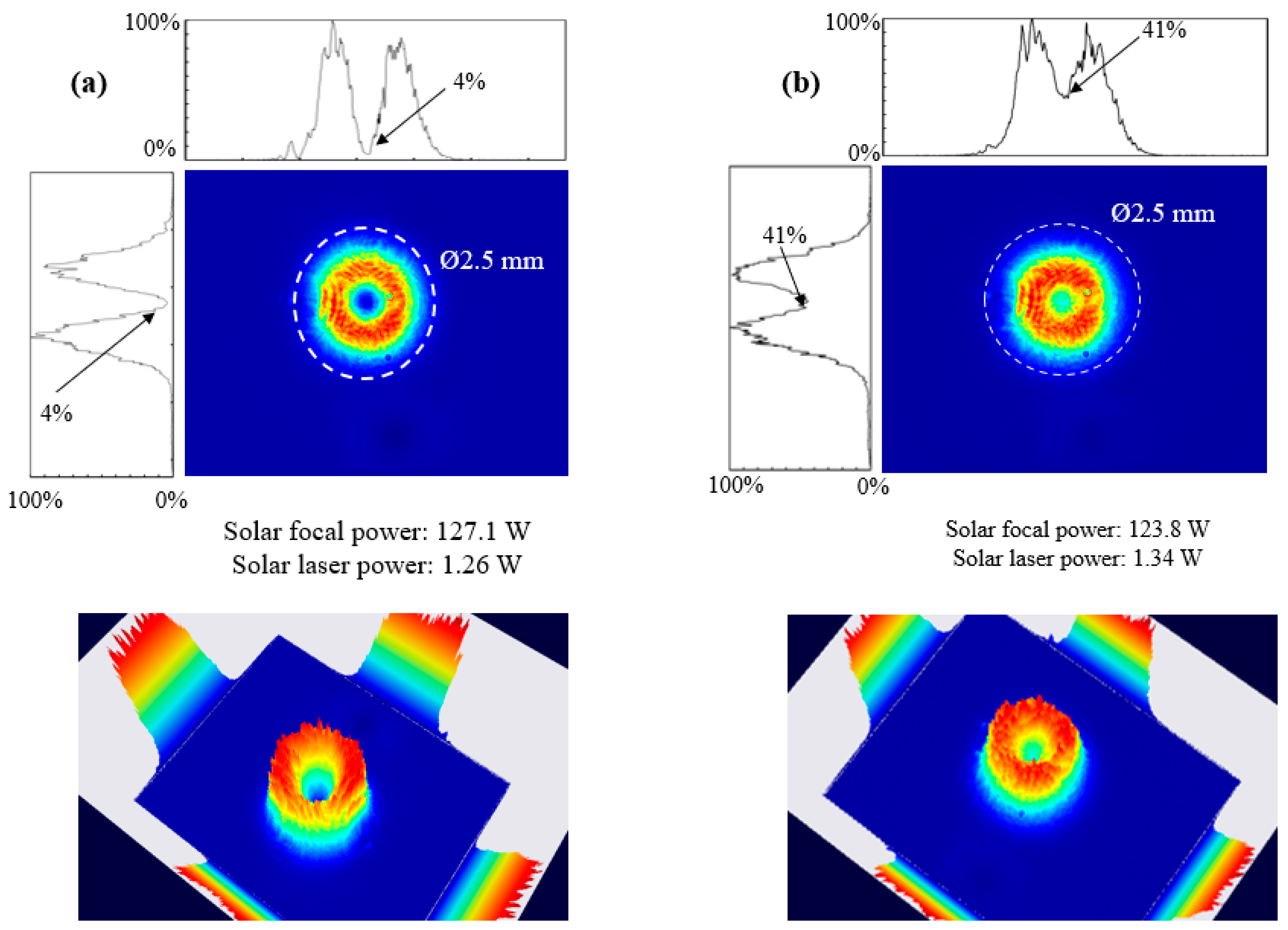
| Maximum intensity at the center | 18% | 4% | ×0.22 |
| Beam size (diameter) | 1.6 mm | 2.5 mm | ×1.56 |
| Energy wall thickness (60% at maximum energy intensity) | 0.30 mm | 0.39 mm | ×1.30 |
| Parameters | Vistas et al., 2019 [6] | This Work | Improvements |
|---|---|---|---|
| Sky status | Clear | Clear | |
| Primary concentrator | Parabolic mirror (NOVA) | Parabolic mirror (PROMES-CNRS) | |
| Total reflectivity of the collection system | 75% | 59% | |
| Tracking method | Via heliostat | Via heliostat | |
| Active medium Pumping method | Nd:YAG End-side-pump | Ce:Nd:YAG End-side-pump | |
| Laser rod dimensions | Ø 4.0 mm × 35 mm | Ø 2.5 mm × 25 mm | |
| Solar irradiance | ~850 W/m2 | ~950 W/m2 | |
| Effective collection area | 1.000 m2 | 0.226 m2 | ×0.32 |
| Maximum solar power at the focus | 636.0 W | 123.8 W | ×0.19 |
| Maximum laser power | 4.50 W | 1.34 W | ×0.30 |
| Solar collection efficiency | 4.50 W/m2 | 5.93 W/m2 | ×1.32 |
| Solar-to-laser conversion efficiency at the focus | 0.70% | 1.08% | ×1.41 |
| Maximum intensity at the center | 57% | 41% | ×0.89 |
| Beam size (diameter) | 1.6 mm | 2.6 mm | ×1.63 |
| Energy wall thickness (60% at maximum energy intensity) | 0.31 mm | 0.52 mm | ×1.63 |
Disclaimer/Publisher’s Note: The statements, opinions and data contained in all publications are solely those of the individual author(s) and contributor(s) and not of MDPI and/or the editor(s). MDPI and/or the editor(s) disclaim responsibility for any injury to people or property resulting from any ideas, methods, instructions or products referred to in the content. |
© 2023 by the authors. Licensee MDPI, Basel, Switzerland. This article is an open access article distributed under the terms and conditions of the Creative Commons Attribution (CC BY) license (https://creativecommons.org/licenses/by/4.0/).
Share and Cite
Garcia, D.; Liang, D.; Almeida, J.; Catela, M.; Costa, H.; Tibúrcio, B.D.; Guillot, E.; Vistas, C.R. Efficient Production of Doughnut-Shaped Ce:Nd:YAG Solar Laser Beam. Sustainability 2023, 15, 13761. https://doi.org/10.3390/su151813761
Garcia D, Liang D, Almeida J, Catela M, Costa H, Tibúrcio BD, Guillot E, Vistas CR. Efficient Production of Doughnut-Shaped Ce:Nd:YAG Solar Laser Beam. Sustainability. 2023; 15(18):13761. https://doi.org/10.3390/su151813761
Chicago/Turabian StyleGarcia, Dário, Dawei Liang, Joana Almeida, Miguel Catela, Hugo Costa, Bruno D. Tibúrcio, Emmanuel Guillot, and Cláudia R. Vistas. 2023. "Efficient Production of Doughnut-Shaped Ce:Nd:YAG Solar Laser Beam" Sustainability 15, no. 18: 13761. https://doi.org/10.3390/su151813761
APA StyleGarcia, D., Liang, D., Almeida, J., Catela, M., Costa, H., Tibúrcio, B. D., Guillot, E., & Vistas, C. R. (2023). Efficient Production of Doughnut-Shaped Ce:Nd:YAG Solar Laser Beam. Sustainability, 15(18), 13761. https://doi.org/10.3390/su151813761