Abstract
Due to their great efficiency and minimal loss, self-priming jet pumps are frequently employed in a variety of sectors for sustainable development. A short jet self-priming pump’s steady and unsteady flow characteristics are investigated numerically in this study using a standard k-ε turbulence model. The precision and dependability of the numerical calculations used in this work are demonstrated by the less than 2% difference between the pump performance data from the numerical calculation and the external characteristics test results for each flow condition. It was found that due to the perpendicularity of the nozzle axis to the impeller axis, the high-flow velocity zone in the nozzle gradually deviates to the side away from the impeller under high-flow conditions. Backflow is generated on the side close to the impeller, where eccentric vortices are created. As time progresses, the asymmetry of the low-pressure zone within the impeller becomes more pronounced under high-flow conditions, and the fluid is unable to form a stable vortex structure at a specific location. This is an important cause of impeller vibration and noise. The nonlinear vibration at the impeller inlet is less periodic, while the increase in flow rate can make the nonlinear vibration generated within the impeller more regular and stable. This reflects the fact that the fluid flow at small flow rates is more likely to be affected by the blade configuration and the shape of the flow channel, which leads to fluid instability and discontinuity. For various flow rates, the main frequency of the pressure pulsation is higher at the impeller intake (W1) than it is in the impeller channel (W2~7). Additionally, the pressure pulsation is more frequent before 10 times the rotational frequency, with no significant regularity. This suggests that the impeller and injector rear chamber dynamic and static interference impacts may have some bearing on the pressure pulsation. The pressure pulsation coefficients (W2~7) in the impeller at different flow rates show an exponentially decreasing trend with the increase of multiples of five in the rotation frequency. The equations for the relationship between CP and 5NF were obtained, respectively: CP-Q1 = 0.07044 × exp(−0.2372NF), CP-Q3 = 0.06776 × exp(−0.2564 NF), CP-Q5 = 0.07005 × exp(−0.2884 NF). The findings of this study contribute to understanding the flow inhomogeneities inside the pump as well as the analysis of the internal pump vibration, enhancing the jet pump’s efficiency and lifespan.
1. Introduction
The traditional self-priming centrifugal pump assembly has a complex structure, and it is difficult to ensure hydraulic efficiency. Furthermore, the power generation, petroleum, and chemical sectors find it difficult to modernize their pumps because of their often massive bodies [1,2,3]. Fluids that are corrosive, abrasive, and include solid particles are frequently transported using self-priming jet pumps, which do not have dynamic seals or moving components. It does not cause mechanical wear or leakage issues because of its effectiveness. Therefore, it is crucial to do research on self-priming jet pumps to decrease energy waste and advance sustainable development.
Researchers looked at the cavitation reactor’s cavitation-generating process and the effects of various component settings on the cavitation characteristics in their work on improving the performance of jet self-priming pumps [4,5,6]. Scholars also studied the effect of various geometric parameters in the injector structure on jet self-priming pumps. Sheha et al. [7] found through numerical simulations that the diffusion angle at optimum efficiency was 5° and the relative length of the mixing chamber was 5.48. Kwidzinski et al. [8] achieved good predictions of outlet pressure and temperature. Aissa et al. [9] demonstrated the theory that changing the jet pump area ratio could change the jet pump’s performance. Additionally, several academics participated in t experimental investigations on the effects of the nozzle profile, flow ratio, and distance between the nozzle and throat on pump efficiency and self-priming performance [10,11,12]. Bauzvand et al. [13] investigated a new geometry of an injector using CFD. The results showed that the new injector had a better entrainment ratio and efficiency than conventional injection under similar working conditions. A maritime gas turbine disk cavity’s flow and performance were investigated by Hu et al. [14] at various nozzle pressures and slow rotating speeds. The study’s findings provided accurate predictions regarding the matching properties of pre-rotating nozzles and slanted receiving holes.
In the study of the internal flow characteristics of self-priming jet pumps, numerous scholars used numerical simulations to investigate the self-priming process, cavitation phenomenon, and two-phase flow characteristics inside the pumps [15,16,17,18,19,20]. Jet self-priming pumps’ vortex flow pumping and fluid-induced vibration have both been explored by academics. Li et al. [21] found that the nonlinear flow mechanism in the critical transition state of MVCT leads to complex oscillatory phenomena generated by pressure pulsations. Based on the Flügge shell hypothesis, Wang et al. [22] looked into how the vibrational properties of thin-walled cylindrical shells evolved. Finally, a straight crack diagnosis approach based on intrinsic frequency contours and amplitude maximization, as well as a method for nonlinear vibration response analysis, were developed. For the gear mesh lubrication thermal fluid field, Gu et al. [23] suggested a dynamic modeling and solution approach. The dynamic evolution rule and heat transfer characteristics were analyzed at different rotational speeds and steering angles. Long et al. [24] investigated experimentally and numerically calculated vortex structures generated in the fast-rapid area of a jet pump under different cavitation conditions. The study summarized the primary elements influencing the development of vortex structures in the fast-rapid flow area and showed the flow features in the fast-rapid flow area at various cavitation stages. In their investigation of the pump’s nonconstant flow features, Zhao et al. [25] investigated the kinetic behavior of water jet propulsion pump blade cavitation under nonuniform guide vane wake disturbance. Zhang et al. [26] investigated the conventional flow patterns and development of a centrifugal pump under rotating stall conditions and elucidated the relative velocity distributions of important internal components. Hu et al. [27] found a strong correlation between the long and short blade structures and the characteristic frequency and root mean square pressure pulsation amplitude of the pressure pulsations. The pressure pulsation in the pump outlet pipe as a whole decreased with increasing distance from the impeller.
The research of the above scholars mainly focuses on the optimization of the structure of the injector as well as the internal flow characteristics of the jet self-priming pump under the coaxial situation of the nozzle and the impeller. However, there are fewer studies on the internal flow characteristics of jet self-priming pumps when the nozzle axis is perpendicular to the impeller axis [28,29]. In order to fill this gap, the numerical calculations in this paper are combined with experiments on the external characteristics of the pump to investigate the internal steady and unsteady flow characteristics of a short jet self-priming pump under various flow circumstances. This covers the jet pump’s steady-state complete flow field, the impeller flow field’s characteristics for changing over time, and the features of the pressure pulsations in the time and frequency domains. The results of the study may not only help to provide insight into possible flow inhomogeneities but also help to reduce component damage caused by irregular nonlinear vibrations, thereby improving jet pump performance and service life [30].
2. Mathematical Models and Calculation Methods
2.1. Geometry
JET series jet pumps are characterized by a deep suction range, a high head, a short self-priming time, smooth operation, etc. The JET1100 model is the intermediate model in this series of jet pumps. An in-depth study of the JET1100 model allows the establishment of benchmarks on performance characteristics at different flow conditions, which in turn can be used to predict and optimize the performance of other models of jet pumps. This cross-model prediction aids in raising the jet pump’s general effectiveness and performance. It also helps engineers better tune relevant parameters to optimize design and performance.
Therefore, the JET1100 jet self-priming pump is the subject of the study, as seen in Figure 1. Its general hydraulic design characteristics are a rated head H of 28 m, a rated flow rate Q of 3 m3/h, and a speed n of 2850 r/min. The injector system described in the text consists of a nozzle, a nozzle tube, an injector front chamber, and an injector rear chamber. Figure 2 illustrates the main dimensions of the injector and impeller, where the nozzle outlet diameter D1 is 9 mm, the effuser diameter D2 is 15 mm, the inlet diameter D3 is 47.5 mm, the outlet diameter D4 is 129.5 mm, the nozzle length L1 is 22 mm, the entrance region length L2 is 12.5 mm, the throat length L3 is 25 mm, the divergent cone length L4 is 62 mm, the number of blades Z is six, the blade placement angle of inlet β1 is 36°, the blade placement angle of outlet β2 is 37.5°, and the blade wrap angle φ is 106°.
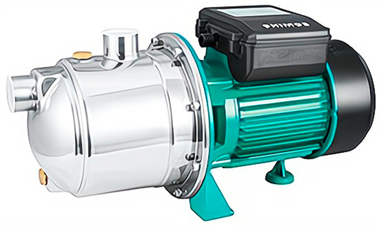
Figure 1.
Jet self-priming pump.
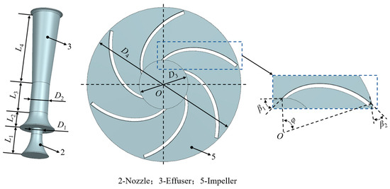
Figure 2.
The main dimensions of the injector and impeller.
2.2. Computational Domains and Boundary Conditions
Figure 3 displays the domain of computation for the jet self-priming pump components discussed herein. When the pump turns on, the high-pressure medium in the guiding vane’s rear chamber sprays through the nozzle and into the effuser, creating a negative jet pressure at the nozzle’s inlet location. The air in the front chamber of the intake is drawn into the effuser by the negative pressure and expelled after passing the impeller and guide vane, causing the pump to self-prime. After the pump completes the self-priming process, the ejector at the front of the impeller still causes the high-pressure medium flowing from the guide vane to be ejected from the nozzle into the effuser.
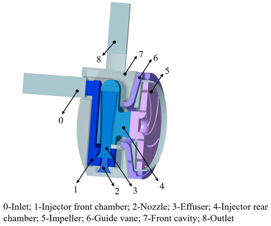
Figure 3.
Water body of each component in the computational domain.
ICEM 14.5 software is employed to grid the whole fluid domain of the jet self-priming pump. Figure 4 illustrates the major computational domain’s meshing elements. Among them are the inlet part, injector structure, impeller, and outlet part of the more regular water body for hexahedral meshing. The complex front cavity and guide vane are divided using an unstructured meshing with better adaptability. The number of impeller grids is 680,000, the number of guide vane grids is 530,000, the number of nozzle grids is 210,000, the number of effuser grids is 330,000, the number of injector front chamber grids is 630,000, the number of injector rear chamber grids is 380,000, the number of grids of the remaining components is 1,130,000, and the total number of grids of the jet pump is 3,890,000. The mesh division ratio is 1.2 to 1.5, and the mesh quality is all greater than 0.6.
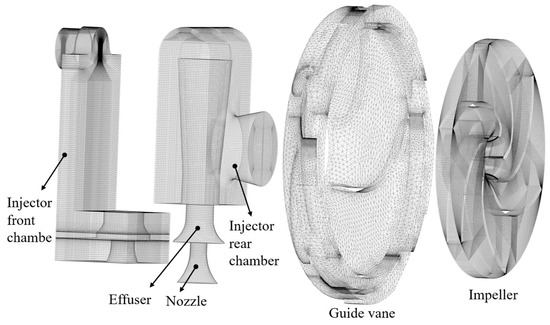
Figure 4.
Mesh of the main parts of the computational domain.
The entire computational domain undergoes numerical simulation employing ANSYS CFX 14.5 software, with the inlet configured as a pressure inlet and the outlet as a mass flow outlet. Set the impeller to the rotational computational domain and the rest of the computational domain to the stationary domain. The interface between the moving and static parts is handled by Frozen-rotor. The SIMPLE algorithm is used in this paper. When the residual value of the control equation is less than 10−4, the solution is determined to have converged. In the steady-state calculations, the inlet pressure was set to 0 atm, the reference pressure to 0 atm, and the outlet mass flow was set to 1, 2, 3, 4, and 5 m3/h, respectively. For unsteady state calculations, the steady state results file serves as the initial file for commencing the unsteady state calculations. The time step was chosen to be 0.00011696 s, CFL = 0.83, and the total time was 0.1684224 s. One step is calculated for every 2° rotation of the impeller, and a total of 1440 steps are calculated, with 20 iterations per step. Processing is performed by the Transient Rotor Stator on the moving and static intersections.
2.3. Turbulence Modeling and Computational Setups
Jet self-priming pumps have many more complex geometries, and the use of a standard k-ε turbulence model not only helps to avoid instability and divergence problems in the numerical solution but also has a faster computational speed. The flow within the injector is predominantly shear laminar, and the overall pressure gradient within the pump is not significant. The model assumes that the fluid is incompressible, the turbulence is isotropic, and the backpressure gradient is small. The model is more accurate for identifying the characteristics of the flow field in the jet self-priming pump, so the standard k-ε turbulence model is selected as the control equation in this paper. The equations for turbulent kinetic energy k and dissipation rate ε are shown below [31,32]:
where C1ε, C2ε, C3ε are constants, Gk denotes the turbulent kinetic energy due to the laminar velocity gradient, σk and σε are the turbulent Prandtl numbers for the k and ε equations, Gb is the turbulent kinetic energy due to buoyancy, YM is the fluctuation due to the diffusion of the transition in compressible turbulence, and Sk and Sε are user-defined source terms.
The calculation formula of turbulent viscosity coefficient is:
where Cμ is a constant.
2.4. Grid Independence
In general, the resolution of the grid has a large impact on the effect of numerical simulation, so it is necessary to verify the irrelevance of the mesh. Due to the large number of flow-through components of this jet self-priming pump, the impact of conducting a grid number study for all flow-through components is minimal. As shown in Table 1, five mesh schemes are set up for the main components of computational analysis. From the external characteristics obtained from the numerical calculations, it can be found that the values of the pump head, power, and efficiency change very little as the amount of the grid grows. Among them, only the number of meshes differs between Schemes 4 and 5, and the results obtained from numerical simulations are basically the same. This indicates that the quality of the mesh at Scheme 4 has reached a high level of accuracy, and the mesh division standard of Scheme 4 is selected for subsequent calculations in order to save computational resources. The computational domain of this research has an entire 3.89 million grids, with a grid quality of more than 0.6 for each component.

Table 1.
Grid independence.
2.5. Numerical Validation
Figure 5 shows the performance of a pump during numerical simulation and testing at various flow rates. When Q is between 1 and 3 m3/h, the difference between the simulation and the test for each performance parameter of the pump fluctuates in a small range, and the head and power calculated numerically at this time have a certain deviation from the test results. When compared to an ordinary centrifugal pump, the ejector structure in the front portion of the impeller gives the flow field structure inside each component of the pump a stronger coupling impact. When Q = 3 m3/h, there is a difference of 0.33% in power, 0.89% in the head, and 0.6% in efficiency between the numerical simulation and experimental values. The numerical calculation technique used in this study is very accurate for estimating the performance and flow structure of the jet pump under rated flow settings, as shown by the fact that all three discrepancies are less than 2%. When Q > 3.5 m3/h, the simulated and experimental values of each performance parameter of the jet pump are gradually approached. In particular, when Q = 5 m3/h, the basic agreement between the simulated and experimental values of each performance parameter further demonstrates the high precision of the numerical calculation in this study.
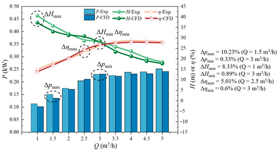
Figure 5.
Comparison of a jet self-priming pump test and numerical calculation.
3. Results and Analysis
3.1. Steady-State Full Flow Field
Figure 6 illustrates the narrowing of pressure within the front cavity and outlet pipe as the flow rate increases. A low-pressure zone begins to appear in the impeller channel and gradually expands, while the effuser throat pressure gradually decreases. By the time the flow rate increased to 4 m3/h, there was already a significant low-pressure zone in the throat. At a flow rate of 5 m3/h, the low-pressure zone here has spread throughout the effuser and propagates downstream through the rear chamber of the injector. A large low pressure zone at the impeller inlet will affect the performance of the pump because as the flow rate increases, the effuser throat pressure decreases in order to reel in more media. When the throat pressure is lower than the local vaporization pressure, the gas phase produced by cavitation can block the passage flow path of the media in the effuser. Due to the action of the jet, the gas phase will be impacted and shot into the injector rear chamber, affecting the flow of the medium in the injector rear chamber, leading to the turbulence of the medium entering the impeller, generating a wide range of low-pressure areas, and affecting the performance of the pump. Therefore, the use of a suitable throat diameter has a positive effect on the suppression of cavitation under high-flow conditions.
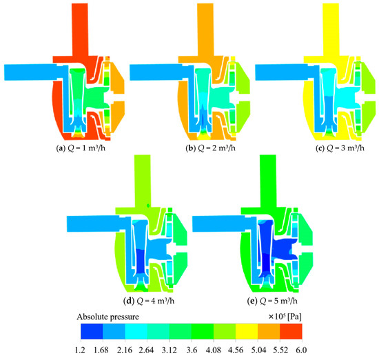
Figure 6.
Cloud plot of pressure at the axial plane in a short jet self-priming pump at different flow rates.
From Figure 7, it is evident that the highest flow velocity in the short jet self-priming pump is predominantly localized at the nozzle outlet and the effuser. As the flow rate increases, the flow rate at the nozzle outlet decreases, and the high-flow rate zone in the effuser is gradually shifted towards the left side wall of the effuser. At the same time, it can be observed that the area where the deflection occurs is also changing, gradually moving closer to the nozzle outlet from the effuser area. This is due to the fact that as the flow rate continues to increase, the impeller head begins to decrease, and the energy entering the front cavity via the impeller gradually diminishes. The flow rate into the nozzle is reduced, while a low-pressure zone occurs at the throat of the effuser, resulting in a weakening of the medium’s ability to be coiled and sucked. As a result, under high-flow conditions, high-flow velocity excursions begin to occur close to the nozzle outlet.
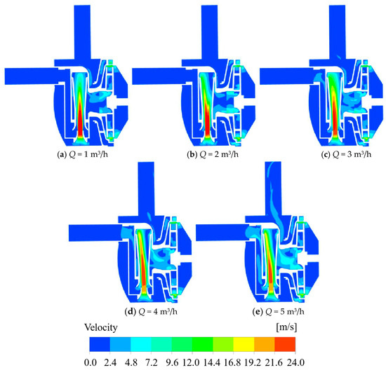
Figure 7.
Cloud plot of velocity at the axial plane in a short jet self-priming pump at different flow rates.
The area showcasing the greatest turbulent kinetic energy within the short jet self-priming pump is prominently visible in Figure 8, primarily distributed within the effuser. As the flow rate continues to increase, its position gradually shifts from the effuser inlet to the effuser outlet. Simultaneously, the region characterized by elevated turbulent kinetic energy within the effuser is undergoing contraction. This is due to the deviation of the high velocity zone in the effuser, which leads to the concentration of the medium ejected from the left side of the outlet and the backflow on the right side. The energy exchange at the effuser outlet is vigorous, the flow is disordered, and a large hydraulic loss is generated. Simultaneously, while the area of high turbulent kinetic energy relocates from the central part of the effuser to its outlet, the high-flow-velocity zone within the effuser undergoes a gradual reduction, accompanied by a gradual decrease in turbulent kinetic energy. As depicted in Figure 9, the distribution of turbulent kinetic energy among the flow channels within the impeller is not uniform. With the escalation of flow rate, the turbulent kinetic energy at the impeller inlet experiences a gradual augmentation, ultimately resulting in an upsurge in the turbulent kinetic energy in proximity to the inlet within the impeller channel. Due to the elevated flow velocity at the impeller inlet, the strength of the eccentric vortex at the impeller inlet experiences augmentation. Therefore, the dissipation at the impeller inlet increases, resulting in greater turbulent kinetic energy. Concurrently, the vortex diffuses into the impeller channel, causing a large hydraulic loss near the inlet of the impeller channel.
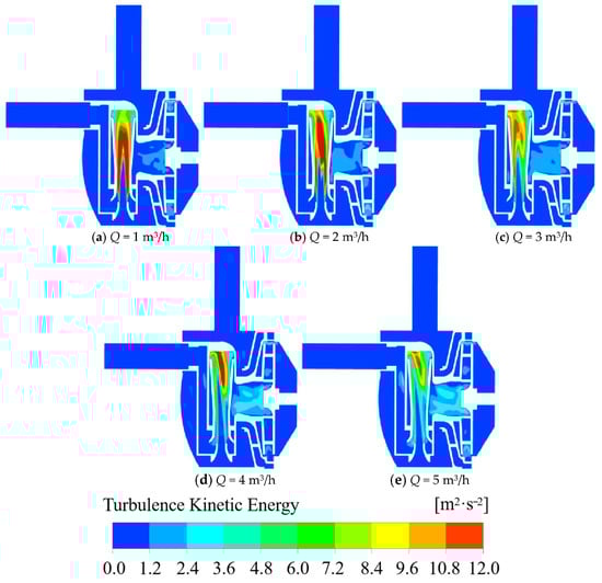
Figure 8.
Cloud plot of turbulent kinetic energy at the axial plane in a short jet self-priming pump at different flow rates.
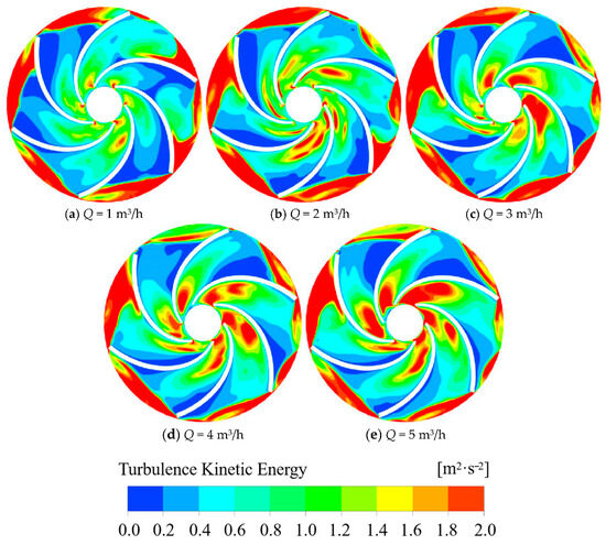
Figure 9.
Cloud plot of turbulent kinetic energy in the midsection of the impeller at different flow rates.
In general, as the flow rate escalates, the low-pressure zone and high-velocity region inside the nozzle progressively move towards the effuser outlet. At the same time, it deviates to the side away from the impeller and produces backflow on the side near the impeller. The eccentric vortex appears at the inlet of the impeller and gradually diffuses to the impeller channel, resulting in a large turbulent kinetic energy. This is likely caused by the nozzle axis being perpendicular to the impeller axis, and the pump’s performance can be improved by using the appropriate throat diameter.
3.2. Unsteady Flow Field Inside the Impeller
The impeller flow channel is divided into six parts, and the flow regime of each flow channel is analyzed and studied. The specific arrangement is shown in Figure 10.
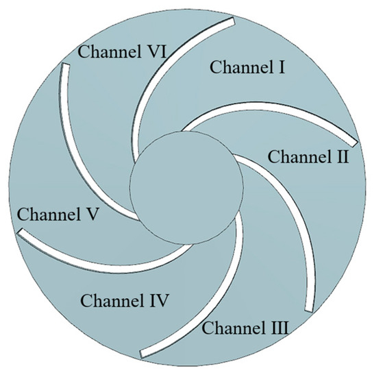
Figure 10.
Schematic diagram of impeller flow channel division.
Figure 11a shows the flow of media, the media in the impeller inlet pressure minimum, the pressure in the impeller channel gradually rising, and finally the impeller outlet pressure maximum, which is in line with the impeller. It has a pressurized media discharge working principle. Concurrently, it shows that as the flow rate increases, the pressure in each flow channel of the impeller gradually decreases. In Figure 11b–d, it is shown that the pressure distribution in each flow channel of the impeller is not uniform at different times under different flow rates, which may be the reason for the vibration and noise of the impeller. At low-flow conditions (Q = 1 m3/h), the range of low-pressure zones in the impeller increases and then decreases with time. When t = 5/6 T, the low-pressure zone within the flow channel V begins to segregate, indicating that unsteady flow is generated at this point. Under the rated flow condition (Q = 3 m3/h), when t =1/6 T, the region with the lowest pressure first appears in the flow channel VI. With time, at t =3/6 T, the region with the lowest pressure spreads into the flow channel V. At t = T, the region with the lowest pressure in the flow channel VI gradually disappears, and only a smaller area of the lowest pressure region exists in the flow channel I. In the case of high-flow rates (Q = 5 m3/h), low-pressure zones appeared in flow channels V, VI, and I at different moments. At this point, the minimum pressure is less than the standard atmospheric pressure value, which indicates that cavitation occurs in the impeller channel and begins to affect the flow regime of the medium in the impeller. Under high-flow conditions, the low-pressure area is mostly spread towards the back of each runner blade. This is because, as the impeller inlet flow rate increases, the impeller rotation generates centrifugal force. The flow of media in the flow path interaction generated by the secondary flow impact on the back of the impeller reduces its pressure and creates a low-pressure zone.
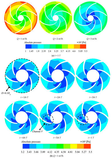
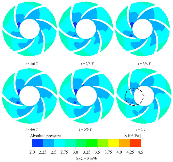
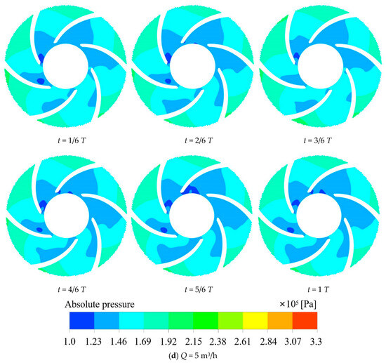
Figure 11.
(a)—Cloud plot of pressure in the midsection of the impeller at different flow rates; (b–d)—Cloud plot of pressure variation with time for the midsection of the impeller.
Figure 12 shows that the trends of the impeller’s middle section velocity changes at various times when Q = 1, 3, or 5 m3/h are all close to the same. The media flow rate is larger at the impeller inlet and gradually decreases when passing through the impeller runner, and the speed gradually increases at the impeller outlet. This is attributed to the impeller’s rotational centrifugal force, energy accumulation in the medium in the flow channel, and contact with secondary flow in the flow channel, which lowers the flow rate. However, at the exit, the media is thrown out due to the centrifugal force increasing its flow rate. Additionally, it has been discovered that the flow field within each of the impeller’s flow channels exhibits asymmetry at various times and at various flow rates, and the strength of the vortex formed is also quite diverse. This is because the media flow rate into the impeller channel was changed, resulting in the strength of the phenomenon of secondary flow in various flow channels also being very varied. In addition to creating a vortex on the blade’s working surface, the media flow’s instability at the impeller outlet also causes an increase in the vortex’s strength there.
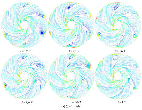
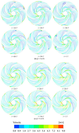
Figure 12.
Streamline plot of variation with time for the midsection of the impeller.
When Q = 1 m3/h, there are more vortex structures generated in each flow channel of the impeller, and there are vortices with different vortex strengths in almost every flow channel at different moments. With the change of time, the intensity of the vortex in flow channel II gradually decreases, and at t = T, only a tiny vortex exists at the impeller outlet. The vortex at the working surface of the blade in flow channel III gradually disappears, and at the same time, the strength of the vortex at the back of the blade can be monitored to gradually increase. This is due to the high impeller speed under the low-flow conditions, at different moments, the media velocity distribution entering the impeller flow channel is not uniform, the flow rate at the inlet biased towards the blade working surface is large. When Q = 3 m3/h, the vortex structure generated in each flow channel of the impeller is significantly reduced, the flow regime of the medium in the flow channel is significantly improved, and only the more significant vortex exists in flow channels I and VI. This is due to the increased ability of the impeller to do work and the increased ability to roll and suck the media into the impeller flow path, thus allowing the media to flow more smoothly in the impeller. When Q = 5 m3/h, the streamlines in the impeller channels are smoother, and only a small range of vortex structure is observed in channel VI. This is because under high-flow conditions, the increase in impeller inlet speed makes the medium enter the impeller channel at a higher speed, thus impacting the impeller channel and enhancing the flow regime inside the impeller.
Overall, the distribution of low-pressure zones in each runner of the impeller at different moments at different flow rates is not uniform, which will cause the impeller to vibrate and make noise. As time progresses, the asymmetry in the low-pressure zone for higher flow conditions becomes more pronounced. This may be due to the fact that the nozzle axis is perpendicular to the impeller axis, and the increase in flow velocity causes the fluid to rotate more eccentrically. Moreover, under high-flow conditions, the fluid is unable to form a stable vortex structure at a specific location, making the presence of vortices almost impossible to observe.
3.3. Pressure Pulsation in the Impeller
3.3.1. Arrangement of Monitoring Points and Determination of Parameters
Due to the uneven pressure distribution in each runner of the impeller, a total of seven monitoring points from W1 to W7 were set up in the impeller inlet and each runner, as shown in Figure 13, to study the pressure pulsation patterns of the impeller inlet and flow channels [33,34].
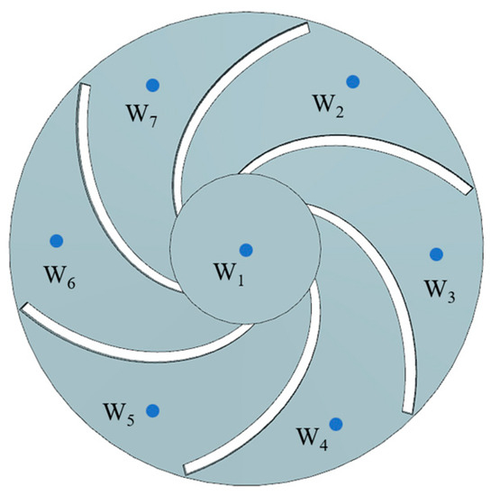
Figure 13.
Arrangement of monitoring points.
For the purpose of eliminating the influence of static pressure on the flow field of the jet self-priming pump, a dimensionless coefficient Cp is applied to characterize the pressure pulsation in the flow field. The coefficient of pressure pulsation Cp is defined as follows:
where is an abbreviation for static pressure, which is the average pressure for one spin cycle. p stands for the static pressure reading in Pa at a particular time at a monitoring station. The symbol ρ symbolizes the fluid density in kg/m3. The impeller output circumferential velocity is shown by the symbol u in units of m/s.
The rotational frequency of a jet self-priming pump can be obtained from the impeller rotation speed as follows:
The frequency is converted to a multiplier of the rotational frequency of the impeller for ease of observation. The multiplier of rotational frequency NF is defined as follows:
where n represents the impeller speed in r/min, and f represents the frequency obtained after a fast Fourier transform in Hz. For both a time-domain and a frequency-domain study of the pressure pulsation, the data from the four most recent cycles are used once the computation results have stabilized.
3.3.2. Characterization of the Time Domain
The pressure pulsations at monitoring locations W2~W7 in the impeller flow channel exhibit good periodicity at various flow levels, as illustrated in Figure 14. Because of the impact of the impeller rotation during a cycle, the pressure in the impeller flow channel exhibits alternating fluctuations. The pressure pulsation at monitoring location W1 at the impeller inlet has weak periodicity, and when the flow rate rises, the magnitude of the pressure pulsation varies noticeably. The reason for this is that the media does not flow inlet from the center of the impeller inlet because of the eccentric rotation of the impeller inlet during the flow of the medium into the impeller through the rear chamber of the injector. Pressure variations at the impeller inlet become more intense as the flow rate rises because the intensity of the medium’s eccentric spin at the impeller inlet rises along with it.
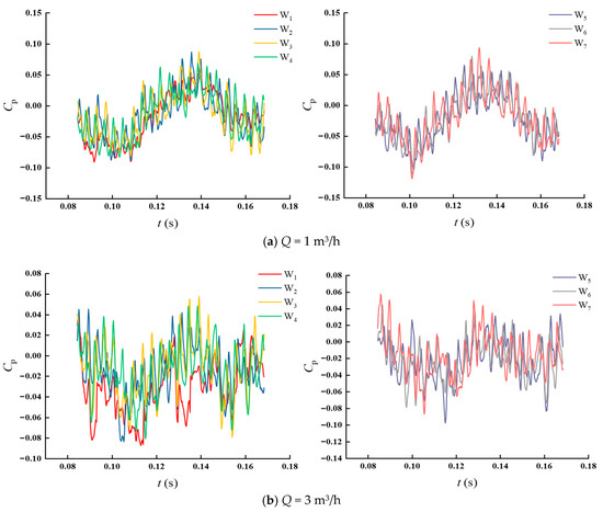

Figure 14.
Time domain plot of pressure pulsation.
Figure 15 shows a plot of the maximum and minimum difference between the peaks and troughs of the pressure pulsations at each monitoring point during a cycle. Evidently, the peak mean of pressure pulsation is larger at Q = 1 m3/h, and the greatest disparity is observed at monitoring point W3. This is due to the fact that fluid flow may be more susceptible to blade configuration and runner shape under low-flow conditions. This leads to instabilities and discontinuities in the fluid, resulting in more irregular nonlinear vibrations. When Q = 3 m3/h, the peak mean of the pressure pulsation at each monitoring point increases and then decreases, which is more regular compared to the low-flow condition. The peak mean of the pressure pulsation at each monitoring site is comparable when Q = 5 m3/h. This is due to the faster flow rate of the fluid, the more stable flow, and the averaging of turbulence effects. Overall, the increase in flow causes the impeller to vibrate more regularly and nonlinearly, and the regular vibration helps to more accurately assess the fatigue life of the impeller components.
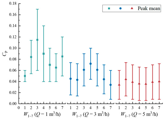
Figure 15.
Peak difference plot of pressure pulsation (maximum and minimum difference between peaks and troughs in one cycle).
3.3.3. Characterization of the Frequency Domain
From Figure 16, it is observed that when Q = 1 m3/h, the dominant frequency of the monitoring points within the impeller is distributed around 0.25 times of the rotational frequency (0.25 F), i.e., a low-frequency region of the rotational frequency F. The secondary dominant frequency distribution of the impeller inlet monitoring point W1 is not obvious. This is due to the medium at the impeller inlet by the impeller and the injector rear chamber’s role in static and dynamic interference making the pulsate more turbulent, resulting in poor symmetry of the flow field. At rated flow (Q = 3 m3/h), the amplitude of pressure pulsation occurs at one and five times the rotational frequency and its multiple frequencies in the impeller flow channel. In the meantime, as frequency rises, pressure pulsation amplitude declines. This happens as a result of the medium’s fluctuations, which alter the pressure distribution in the impeller flow channel, during the flow from the impeller to the guide vane. The pressure pulsation at the monitoring location W1 at the impeller inlet is more frequent before 10 times the rotational frequency, and there is an significant crossover phenomenon, while after 10 times the rotational frequency, the amplitude of pressure pulsation gradually decreases and tends to level off. When Q = 5 m3/h, the pressure in the impeller runner varies more drastically, and the pressure shows an up-and-down trend. This is attributed to the fact that high-flow rates can easily induce leakage, turbulence, water flow detachment, and cavitation backflow, resulting in large pressure fluctuations.
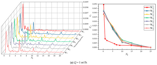
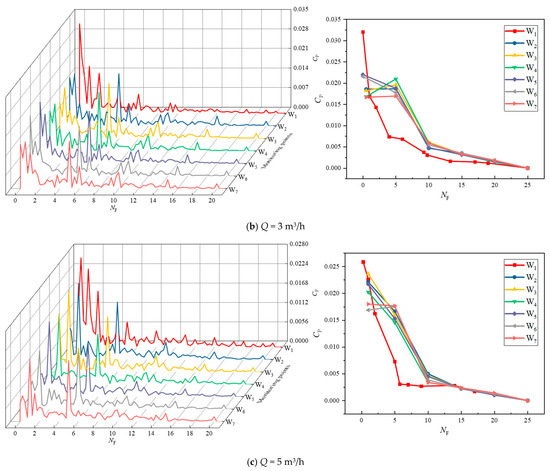
Figure 16.
Frequency domain plot of pressure pulsation. The left figure shows the detailed pattern of change of CP and NF at the monitoring points (W1~7), and the right figure shows the pattern of change of amplitude of CP and NF.
In general, for various flow rates, the amplitude of the main frequency of pressure pulsations at the impeller intake (W1) is greater than the amplitude of pressure pulsations in the impeller channel (W2~7). Additionally, the pressure pulsation is more frequent before 10 times the rotational frequency, with no significant regularity. This indicates that the impeller’s and the injector’s rear chamber have a dynamic and static interference impact that affects the pressure pulsation in a specific way. Within the flow channel, monitoring locations W2~7 appear in amplitude at secondary dominant frequencies of five times the rotational frequency and multiples of the vane passing frequency. This demonstrates that the impeller and guide vane working together have a major impact on the medium in the impeller flow channel.
A similar trend of decreasing pressure pulsation coefficient with increasing five times the rotational frequency can be found in Figure 17 for different flow rates, both showing an exponentially decreasing trend. It can be observed that the pressure pulsation coefficient decreases slightly as the flow rate increases. This is due to the increase in flow velocity within the impeller, which results in improved flow stability, reduced flow separation, and thus improved flow uniformity. The derivation of these curves helps Jet Series jet pumps gain insight into cyclic variations in fluid flow and vibration phenomena and helps predict impeller pressure pulsation variations for other conditions or models.
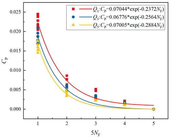
Figure 17.
Frequency domain plot of pressure pulsation at multiples of 5 rotational frequencies (W2~7).
Flow separation, reverse pressure gradients, and complicated turbulent behavior are still limitations of the standard k-ε model, despite its widespread usage in many technical applications. This paper only set up monitoring points for the impeller part, and the other parts of the jet pump did not carry out targeted research. Only the exterior performance test of the jet self-priming pump was conducted because of the circumstances’ restrictions. We recognize the limitations of the study in this paper, which may limit full understanding of the overall jet pump flow behavior. In future research, the group intends to test the cavitation and self-priming processes of the jet pump using the visualization equipment. A more in-depth study of the flow behavior in different parts of the jet pump is carried out to ensure the accuracy and reliability of our results in practical applications.
4. Conclusions
The following findings are reached after discussing the steady-state and unsteady-state flow characteristics within a short jet self-priming pump:
(1) With an escalation in flow rate, the high-flow rate zone in the nozzle gradually shifts to the side away from the impeller and produces backflow on the side close to the impeller. Moreover, the eccentric vortex at the impeller inlet gradually spreads to the impeller channel, generating large hydraulic losses. This is caused by the nozzle axis being perpendicular to the impeller axis, and using the proper throat diameter can improve pump performance.
(2) Overall, the distribution of low-pressure zones in each flow channel of the impeller at different moments at different flow rates is not uniform, and the flow regime has asymmetry. With the passage of time, the asymmetry of the low-pressure zone of the high-flow condition becomes more significant, which is an important cause of vibration and noise generated by the impeller. The increased flow rate makes it more difficult for the fluid to form a stable vortex structure at a given location, which elevates the flow regime within the impeller.
(3) The nonlinear vibrations at the impeller inlet are less periodic. The increase in flow rate makes the nonlinear vibration generated in the impeller more regular and stable. This reflects the fact that the fluid flow at small flow rates is more susceptible to the influence of the blade configuration and the shape of the flow channel, leading to fluid instability and discontinuity.
(4) For various flow rates, the amplitude of the main frequency of pressure pulsations at the impeller intake (W1) is greater than the amplitude of pressure pulsations in the impeller channel (W2~7). Furthermore, the pressure pulsation is more frequent before 10 times the rotational frequency, with no significant regularity. This illustrates that the interaction between the impeller and the rear chamber of the injector, both dynamically and statically, can have an impact on pressure pulsation. The pressure pulsation coefficients at the monitoring points (W2~7) in the impeller at different flow rates show an exponentially decreasing trend with the increase of multiples of five in the rotation frequency. Among them, the relationship equation between Cp and 5NF for low-flow condition is CP-Q1 = 0.07044 × exp(−0.2372NF), the relationship equation between Cp and 5NF for rated flow condition is CP-Q3 = 0.06776 × exp(−0.2564 NF), the relationship equation between Cp and 5NF for large flow condition is CP-Q5 = 0.07005 × exp(−0.2884 NF). These formulas can reveal the vibration characteristics of the impeller more comprehensively and provide a reference for the performance optimization of the pump.
Author Contributions
Data curation, C.W. and S.W.; formal analysis, Y.Y. and G.L.; writing-original draft, H.W. and S.L.; writing-review and editing, H.Y. and Y.Y.; software, W.C. All authors have read and agreed to the published version of the manuscript.
Funding
This research was funded by the National Natural Science Foundation of China (No. 51979240 and 52009013), China Postdoctoral Science Foundation (No. 2023M732828), Sixth “333 Project” Young Talents Program of Jiangsu Province (No. 114), Open Research Fund of Hainan Vocational University of Science and Technology, Jiangsu Province Key R&D Program (No. BE2020330), and Key Laboratory of Modern Agricultural Equipment and Technology (Jiangsu University), Ministry of Education (No. NZ201604).
Institutional Review Board Statement
Not applicable.
Informed Consent Statement
Not applicable.
Data Availability Statement
Not applicable.
Conflicts of Interest
The authors declare no conflict of interest.
References
- Stuparu, A.; Baya, A.; Bosioc, A.; Anton, L.; Mos, D. Experimental investigation of a pumping station from CET power plant Timisoara. IOP Conf. Ser. Earth Environ. Sci. 2019, 240, 032018. [Google Scholar] [CrossRef]
- Shen, Z.; Chu, W.; Li, X.; Dong, W. Sediment erosion in the impeller of a double-suction centrifugal pump—A case study of the Jingtai Yellow River Irrigation Project, China. Wear 2019, 422, 269–279. [Google Scholar] [CrossRef]
- Perissinotto, R.M.; Verde, W.M.; Biazussi, J.L.; Bulgarelli, N.A.V.; Fonseca, W.D.P.; de Castro, M.S.; de Moraes Franklin, E.; Bannwart, A.C. Flow visualization in centrifugal pumps: A review of methods and experimental studies. J. Pet. Sci. Eng. 2021, 203, 108582. [Google Scholar] [CrossRef]
- Wang, J.; Cheng, H.; Xu, S.; Ji, B.; Long, X. Performance of cavitation flow and its induced noise of different jet pump cavitation reactors. Ultrason. Sonochem. 2019, 55, 322–331. [Google Scholar] [CrossRef] [PubMed]
- Choi, Y.-D.; Shrestha, U. Cavitation Performance Improvement of an Annular Jet Pump by J-Groove. KSFM J. Fluid Mach. 2020, 26, 25–35. [Google Scholar] [CrossRef]
- Xu, S.; Wang, J.; Cai, B.; Cheng, H.; Ji, B.; Zhang, Z.; Long, X. Investigation on cavitation initiation in jet pump cavitation reactors with special emphasis on two mechanisms of cavitation initiation. Phys. Fluids 2022, 34, 013308. [Google Scholar] [CrossRef]
- Sheha, A.A.A.; Nasr, M.; Hosien, M.A.; Wahba, E. Computational and experimental study on the water-jet pump performance. J. Appl. Fluid Mech. 2018, 11, 1013–1020. [Google Scholar] [CrossRef]
- Kwidzinski, R. Experimental and theoretical investigations of two-phase flow in low pressure steam–water injector. Int. J. Heat Mass Transf. 2019, 144, 118618. [Google Scholar] [CrossRef]
- Aissa, W.A.; Eissa, M.S.; Mohamed, A.H.H. Experimental and Theoretical Investigation of Water Jet Pump Performance. Int. J. Appl. Energy Syst. 2021, 3, 1–14. [Google Scholar] [CrossRef]
- Zhu, X.; Wang, D.; Xu, C.; Zhu, Y.; Zhou, W.; He, F. Structure influence on jet pump operating limits. Chem. Eng. Sci. 2018, 192, 143–160. [Google Scholar] [CrossRef]
- Wang, Q.; Wang, Y.; Zhu, R.; Cao, P.Y.; Tang, H.T.; Yu, H.Q. Experimental study on the optimal range on nozzle-to-throat clearance of jet centrifugal pump. IOP Conf. Ser. Earth Environ. Sci. 2019, 240, 032033. [Google Scholar] [CrossRef]
- Jiang, T.; Huang, Z.; Li, J.; Zhou, Y.; Xiong, C. Experimental investigation of internal and external flow fields of jetting nozzles with different structures. J. Pet. Sci. Eng. 2022, 217, 110891. [Google Scholar] [CrossRef]
- Bauzvand, A.; Tavousi, E.; Noghrehabadi, A.; Behbahani-Nejad, M. Study of a novel inlet geometry for ejectors. Int. J. Refrig. 2022, 139, 113–127. [Google Scholar] [CrossRef]
- Hu, B.; Yao, Y.; Wang, M.; Wang, C.; Liu, Y. Flow and Performance of the Disk Cavity of a Marine Gas Turbine at Varying Nozzle Pressure and Low Rotation Speeds: A Numerical Investigation. Machines 2023, 11, 68. [Google Scholar] [CrossRef]
- Kong, D.; Pan, Z.; Yang, B. Characteristics of gas-liquid two-phase flow in self-priming pump. J. Drain. Irrig. Mach. Eng. 2022, 40, 15–21. [Google Scholar] [CrossRef]
- Zhao, K.; Cheng, H.Y.; Long, X.P.; Ji, B.; Lai, X. FTLE evaluation method for mixing capacity of jet pump. J. Drain. Irrig. Mach. Eng. 2022, 40, 556–562. [Google Scholar] [CrossRef]
- Chen, W.; Huang, C.; Bai, Y.; Chong, D.; Yan, J.; Liu, J. Experimental and numerical investigation of two phase ejector performance with the water injected into the induced flow. Int. J. Adv. Nucl. React. Des. Technol. 2020, 2, 15–24. [Google Scholar] [CrossRef]
- Chen, X.R.; Xiong, B.; Liu, M.J.; W, J.J. Effect of annular jetting hole specific area on performance of vertical self-priming pump. J. Drain. Irrig. Mach. Eng. 2023, 41, 1–7. [Google Scholar] [CrossRef]
- Bornhoft, B.J.; Edwards, J.R.; Lin, K.-C. Numerical Simulation of Two-Phase Flow Within Aerated-Liquid Injectors. J. Propuls. Power 2019, 35, 1034–1047. [Google Scholar] [CrossRef]
- Qian, H.; Mou, J.; Ren, Y.; Zhu, Z.; Liu, N.; Zheng, S.; Wu, D. Investigation of Self-Priming Process of a Centrifugal Pump with Double Blades. J. Therm. Sci. 2020, 30, 849–858. [Google Scholar] [CrossRef]
- Li, L.; Tan, Y.; Xu, W.; Ni, Y.; Yang, J.; Tan, D. Fluid-induced transport dynamics and vibration patterns of multiphase vortex in the critical transition states. Int. J. Mech. Sci. 2023, 252, 108376. [Google Scholar] [CrossRef]
- Wang, T.; Wang, C.; Yin, Y.; Zhang, Y.; Li, L.; Tan, D. Analytical approach for nonlinear vibration response of the thin cylindrical shell with a straight crack. Nonlinear Dyn. 2023, 111, 10957–10980. [Google Scholar] [CrossRef]
- Gu, Y.; Zheng, G. Dynamic Evolution Characteristics of the Gear Meshing Lubrication for Vehicle Transmission System. Processes 2023, 11, 561. [Google Scholar] [CrossRef]
- Long, Y.; An, C.; Zhu, R.; Chen, J. Research on hydrodynamics of high velocity regions in a water-jet pump based on experimental and numerical calculations at different cavitation conditions. Phys. Fluids 2021, 33, 045124. [Google Scholar] [CrossRef]
- Zhao, G.; Liang, N.; Zhang, Y.; Cao, L.; Wu, D. Dynamic behaviors of blade cavitation in a water jet pump with inlet guide vanes: Effects of inflow non-uniformity and unsteadiness. Appl. Ocean Res. 2021, 117, 102889. [Google Scholar] [CrossRef]
- Zhang, N.; Jiang, J.; Gao, B.; Liu, X. DDES analysis of unsteady flow evolution and pressure pulsation at off-design condition of a centrifugal pump. Renew. Energy 2020, 153, 193–204. [Google Scholar] [CrossRef]
- Hu, J.; Kang, C.; Xing, Z.L.; Zhang, W.B. Effect of long and short blades on outlet pressure fluctuation characteristics of condensate pump. J. Drain. Irrig. Mach. Eng. 2022, 40, 654–659. [Google Scholar] [CrossRef]
- Wang, Y.; Cui, Y.; Wang, K.; Wang, W.; Yin, G. Analysis of unsteady flow in flow-ejecting self-priming centrifugal pump based on les. J. Drain. Irrig. Mach. Eng. 2015, 33, 481–487. [Google Scholar] [CrossRef]
- Guo, R.; Li, R.; Zhang, R.; Han, W. Numerical Study of the Unsteady Flow Characteristics of a Jet Centrifugal Pump under Multiple Conditions. Processes 2019, 7, 786. [Google Scholar] [CrossRef]
- Tang, S.; Zhu, Y.; Yuan, S. An improved convolutional neural network with an adaptable learning rate towards multi-signal fault diagnosis of hydraulic piston pump. Adv. Eng. Inform. 2021, 50, 101406. [Google Scholar] [CrossRef]
- Gusev, A.; Zalesny, V. Analytical solution technique in k-omega and k-epsilon turbulence parameterizations and their implementation in the OGCM. In Proceedings of the EGU General Assembly Conference Abstracts, Online, 4–8 May 2020; p. 17693. [Google Scholar] [CrossRef]
- Adanta, D.; Fattah, I.M.R.; Muhammad, N.M. Comparison of standard k-epsilon and sst k-omega turbulence model for breastshot waterwheel simulation. J. Mech. Sci. Eng. 2020, 7, 39–44. [Google Scholar] [CrossRef]
- Ni, D.; Chen, J.; Wang, F.; Zheng, Y.; Zhang, Y.; Gao, B. Investigation into Dynamic Pressure Pulsation Characteristics in a Centrifugal Pump with Staggered Impeller. Energies 2023, 16, 3848. [Google Scholar] [CrossRef]
- Zhang, S.; Chen, H.; Ma, Z.; Wang, D.; Ding, K. Unsteady flow and pressure pulsation characteristics in centrifugal pump based on dynamic mode decomposition method. Phys. Fluids 2022, 34, 112014. [Google Scholar] [CrossRef]
Disclaimer/Publisher’s Note: The statements, opinions and data contained in all publications are solely those of the individual author(s) and contributor(s) and not of MDPI and/or the editor(s). MDPI and/or the editor(s) disclaim responsibility for any injury to people or property resulting from any ideas, methods, instructions or products referred to in the content. |
© 2023 by the authors. Licensee MDPI, Basel, Switzerland. This article is an open access article distributed under the terms and conditions of the Creative Commons Attribution (CC BY) license (https://creativecommons.org/licenses/by/4.0/).