Article

Study on Overburden Fracture and Structural Distribution Evolution Characteristics of Coal Seam Mining in Deep Large Mining Height Working Face

1
State Key Laboratory of Coking Coal Exploitation and Comprehensive Utilization, Pingdingshan 467099, China
2
State Key Laboratory for Geomechanics and Deep Underground Engineering, China University of Mining and Technology, Xuzhou 221116, China
*
Author to whom correspondence should be addressed.
Sustainability 2023, 15(18), 13365; https://doi.org/10.3390/su151813365
Submission received: 20 July 2023 / Revised: 11 August 2023 / Accepted: 4 September 2023 / Published: 6 September 2023
(This article belongs to the Special Issue Advances in Coal Mine Disasters Prevention)

Abstract

:
Coal mining has gradually entered the deep mining era, and large-height mining is an important way to mine thick coal seams in the deep. The high coal wall will inevitably make the distribution of the overburden structure in the coal mining face more complicated, and the large buried depth will also cause more intense mine pressure. The study of the distribution and evolution of the overburden structure and stress in the mining site can provide theoretical guidance for safe mining. In this work, a physical similarity modeling test was carried out based on the physical–mechanical parameters of overburden rock and similarity theory, taking the mining of a deep, large-height working face in Pingdingshan Coal Mine as an example. The results show that the deformation and breakage of overburden rock in deep, large-height workings occurring during mining is persistent and not only in a short period of time. The breakage form of overburden can be categorized into two types based on the deformation characteristics: (I) non-separation-induced type, and (II) separation-induced type. Among these, the breakage induced by separation can be divided into two categories: (i) dominated by self-weight stress, and (ii) affected by shear cracks. It also summarizes the form of the overburden structure and the structural morphology of the stope. The overburden structure shows a “combined cantilever beam structure-articulated rock-slab structure-non-articulated rock-slab structure”. Among these, the periodic breakage of the upper cantilever beam evolved articulated and non-articulated rock-slab structure in the lower part, which weakened the supporting effect of the lower gangue and further aggravated the breakage of the upper overburden rock. The shape of the main structure of the stope mainly depends on the fracture line from the advancing coal wall to the upper overburden: from a rectangular shape without collapse to a trapezoidal shape at the initial stage of collapse, to a trapezoidal shape with multiple steps after the main roof collapse.

1. Introduction

The world’s most important source of energy is still fossil fuels, and the mining of coal resources is related to the sustainable and healthy development of the national economy [1,2,3]. With the gradual entry of mineral mining into the era of deep earth, how to safely mine deep coal resources has become an important research topic in view of the engineering characteristics of the “three highs and one disturbance” in the deep part of the earth [4,5,6,7]. Reviewing the research from existing scholars in coal seam mining, either from the law of mineral pressure appearance [8,9,10], from the control technology of surrounding rock [11,12,13], or from the structural characteristics of overburden rock. The following will focus on the research of this paper, combing the overburden-rock-structure-related research. For example, scholars have proposed a variety of classical structure hypotheses for overburden, including arches, beams, plates, and other forms. The main hypotheses concerning the arch are the pressure arch hypothesis [14,15,16], the natural equilibrium arch hypothesis [17,18], and the surrounding rock stress shell theory [19,20]. The hypothesis of the beam is widely used, including cantilever beam theory [21,22], masonry beam theory [23,24], transfer rock beam theory [25,26], and elastic foundation beam theory [27,28]. The plate hypothesis mainly includes the thin plate theory [29,30] and the Kirchhoff plate theory [31,32].
Further, scholars have extended these classical hypotheses. In the aspect of high-stress mining sites with large burial depths, some scholars have analyzed the damage mode of overburden rock in high-stress environments: e.g., Meng et al. [33] explored the different damage processes of deep-buried soft rock under the influence of different factors and summarized several failure modes. Cheng et al. [34] jointly applied distributed fiber optic sensing (DFOS), high-density resistivity tomography (HD-ERT), and close-range photogrammetry (CRP) techniques to study the spatial and temporal evolutionary characteristics of overburden deformation in deeply buried quarries, showing that the deformation of mining overburden is a dynamic evolutionary process, and summarizing the damage of overburden into three categories: bending tension damage, integral shear damage, and shear-slip damage. Some scholars have analyzed the damage mechanism of coal pillars and roadways in the working face based on the form of overburden structures in large burial depths. For example, based on the relationship between the overburden structure and the influence of large-scale crushing movement on the damage of coal rock mass, Zhu et al. [35] studied the induced scouring machine of dynamic and static load combination mode of isolated coal pillars in irregular working faces with large buried depths. He et al. [36] used the discontinuous deformation analysis method to numerically study the mechanism of pressure arch formation and anchor support during subsurface excavation in deeply buried stratified rock masses. The effects of burial depth, stratigraphic dip angle, and other factors on the formation of global pressure arches and local voussoir beam arches were investigated. Li et al. [37] analyzed the movement law and stress evolution characteristics of the overburden structure in the step zone of the deep-buried variable-length working face. In addition, scholars have carried out many studies on the roof breakage characteristics, in situ stress distribution characteristics, and surrounding rock stability control technology for deep-buried stopes with different overburden geological conditions [38,39,40].
In terms of large-height mining, scholars have either established the mechanical model of surrounding rock, classified the immediate roof, or predicted and revealed the strong pressure of large-height mining according to the evolution of key layer structure. For example, Liang et al. [41] proposed that there are two structural forms and six movement forms in the key layer of the large-height mining face with large mining height by theoretical analysis method, and revealed the influence of the six-movement forms on the mine pressure based on numerical simulation, which was verified based on on-site measurements. Xu et al. [42] carried out the work on the classification of key layer structures, which were categorized into the “cantilever beam” structural formations in the key layer of collapse zones and stable “articulated” structural formations in the key layer of fracture zone, and gave the conditions for their formation. In addition, the movement patterns of overburden rock under different structural patterns are discussed, and the UDEC numerical simulation method is used to verify the movement patterns of key layers under different formation conditions, which reveals the influence of the movement patterns of key layers on the mine pressure in the quarry and is verified by the field measurement data. Some other scholars have analyzed the means through various engineering measurements and experiments. For example, Li et al. [43] analyzed the influence of large-height mining shallow buried working face movement on the pressure performance of the mine, taking the 1313 oversized mining height top coal release face as an example, and dividing the key strata of the working face. Combining theoretical analysis, on-site measurement, and numerical simulation, the influence mechanism of the key layer was analyzed. Zhang et al. [44] used a variety of field measurement techniques (borehole measurement, displacement observation, and borehole peeping) to monitor the structural changes of overburden rock in large-height working face: roof movement, and discussed the temporal and spatial relationship between overburden structure change and mining pressure based on numerical calculation. Or by proposing a large-height mining masonry beam model and a variety of overburden rock fracture expansion and development mechanisms to explain the law of overburden rock fracture [45,46,47].
In summary, scholars have carried out much useful research on the overburden rock structure of the stope and summarized various structural forms and breakage types for different engineering conditions. However, there are few studies on the breakage and structural evolution of overburden rock in the stope with large buried depth coupled with high coal wall. The mining of deep and thick coal seams often adopts a large mining height working face. The large falling space of the working face with a large height will inevitably make the distribution of the overburden structure more complex, and the large buried depth will also cause more intense mine pressure to appear. Therefore, in this work, based on the physical and mechanical parameters of real overburden rock and similarity theory, the physical similarity modeling test of mining action of deep large-height mining face in the Pingdingshan mining area is carried out. The deformation and breakage characteristics of overburden rock in deep large-height working faces were studied: breakage process, deformation and settlement, breakage form of overburden rock, and type of caving induced by separation. The structural form of overburden rock and the structural form of the stope were also summarized. In addition, the stress distribution evolution law of overburden rock under mining action was analyzed.

2. Engineering Background

2.1. Mining and Geological Condition

The object of the study is the 12,110 large-height mining face in Shoushan No. 1 Mine. The mine is located in the northeast corner of Pingdingshan City, Henan Province, China, with an overall mine area of about 27 km2, a north–south width of about 4.3 km, and an east–west length of about 6.6 km. The 12,110 working face is located in the lower extension east flank of this mining area, with a burial depth of 796.5–881.1 m (in this work, the depth of burial is taken to be 800 m). The thickness of the coal seam planned to be recovered from this working face is 4.6–6.1 m, with an average thickness of 5.6 m (Table 1). The working face is a typical deep large mining height working face. The recoverable coal seam inclination angle of the whole working face is about 7°, which is suitable for adopting a large mining height intelligent integrated mechanized recovery process.
According to the field survey, the coal seam and the upper and lower rock layers are shown in Table 1: the overall thickness of the coal seam is uniform, medium, and thick, with a recoverable index of 1.00 and a variability coefficient of 19.8%, which is suitable for large-height comprehensive mining. The coal produced from this working face is mainly bright coal, black powder, relatively loose and broken, with a hardness range of 0.1–0.4 f. The direct roof of this mining face is mudstone–sandy-mudstone, with a thickness of about 4.5–7.8 m. The basic roof is fine to medium-grained sandstone, with a thickness of about 11.8–19.5 m. The direct bottom is a sandy mudstone interbed, with a thickness of about 4.2–5.8 m. The basic bottom is limestone with a thickness of 21.3–27.5 m.

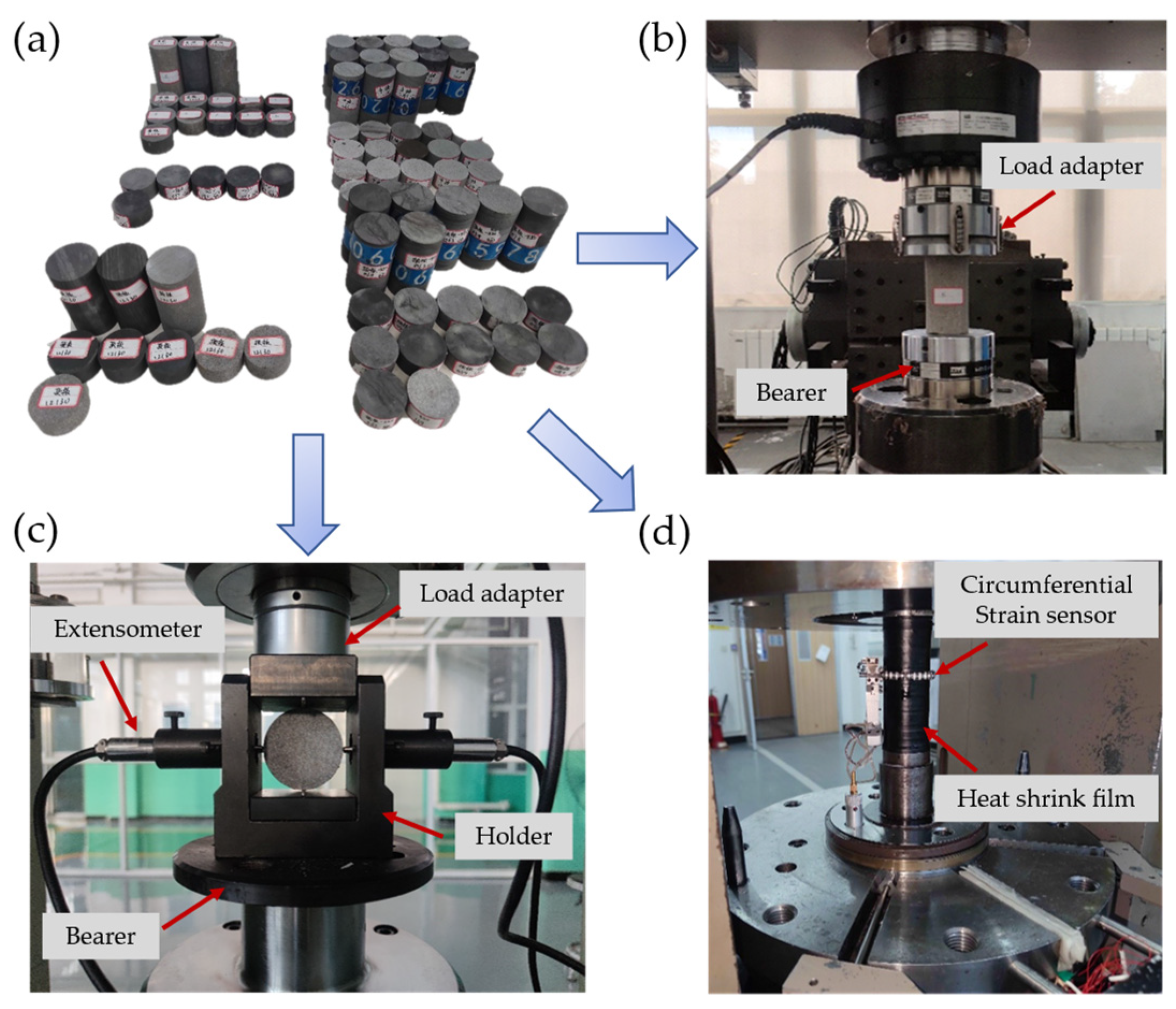
2.2. Experiments for Determining Rock Mechanical Properties

In order to obtain the physical and mechanical parameters of the rock formation, samples were taken from the upper and lower rock layers on the 12,110 working face, and standard specimens of 25 mm in height, 50 mm in diameter, and 100 mm in height and 50 mm in diameter were prepared, as in Figure 1a. The standard specimens were weighed and a uniaxial compression test (Figure 1b), indirect tensile test (Figure 1c), and triaxial compression test (Figure 1d) of the original rock specimens were carried out by using the MTS816 testing machine, the RMT-301 rock direct shear/triaxial compression compound testing machine, and the MTS815 testing machine, respectively. The specific operation standard of the test is based on the method recommended by the International Society of Rock Mechanics (ISRM) [48,49]. The physical and mechanical parameters of the rock layers above and below the working face were obtained as shown in Table 2.

3. Physically Similar Simulation of Overburden Movement under Deep Large Mining Face Mining

3.1. Similarity Theory

The physical similarity model test method has been maturely applied in the research of mine pressure and strata control [50,51,52]. It can clearly and intuitively observe the phenomenon of mine pressure behavior, the migration of overlying strata, and the related conditions of working face. With the help of monitoring equipment, it is possible to qualitatively and quantitatively analyze the deformation, migration, roof breakage, separation development, and stress evolution of overburden rock during the mining of coal seam. Whether the results of the physical similarity model test are reliable depends on the similarity between the similarity model and the actual engineering conditions. Generally, the similarity model test follows the following three similarity laws: the similarity positive law, the similarity π law, and the similarity inverse law [53,54].
The inverse law of similarity points out that the geometric dimensions, initial stress state, and boundary conditions between the engineering prototype and the model should be similar, and the physical quantities that play a key role in the research should also be proportional. Among them, the criterion composed of physical quantities and geometric properties that are strongly correlated or significant to the test results is called the dominant similarity criterion. Although ideally, the model should be similar to the prototype one-to-one, the study of deep underground space is a systematic project with a complex geological background and stress environment. Therefore, it is practically difficult to realize that every physical quantity is similar, and blindly pursuing full similarity will increase the task and deviate from the starting point of simplifying the experiment. According to previous studies, the dominant similarity criterion of this experiment is determined, i.e., satisfying Equation (1) [55]:
f [ P , E , L , R , σ , ε , γ , δ , μ ] = 0
where P is the overlying compensation load, MPa; E is the elastic modulus of rock, GPa; L is the geometric size of the model, m; R is the strength of the rock, MPa; σ is stress on the rock, MPa; ε is the strain on the rock; γ is the bulk density of the rock, N/m3; δ is the deformation of the rock, m; and μ is the Poisson’s ratio of the rock.
Specifically, the geometric size (Lp) of the model should be similar to the geometric size (Lm) of the prototype, and the similarity ratio CL, such as Equation (2) [55].
C L = L p L m
According to the similarity of the phenomenon of similarity test: the trajectories of the corresponding points of the two are similar, then the time similarity coefficient (CT is the ratio of the time spent on the geometric similarity distance between the prototype and the physical similarity model) and the geometric similarity ratio satisfy the relationship of Equation (3) [55]. Among these, tm is the time of the model and tp is the time of the prototype project.
C T = t p t m = C L
In addition, the density similarity ratio is determined according to the weighted average density (ρp) of similar materials and the weighted average density (ρm) of prototype strata, as shown in Equation (4) [55].
C ρ = ρ p ρ m
Furthermore, the stress similarity ratio is determined, as shown in Equation (5) [55]:
C σ = F p F m = m p ( d v p d t p ) m m ( d v m d t m ) = σ p σ m = L p L m γ p γ m = L p L m ρ p ρ m = C L C ρ
where F, m, and v are the force, mass, and velocity within the corresponding system, respectively.

3.2. The Basic Process of the Test Method

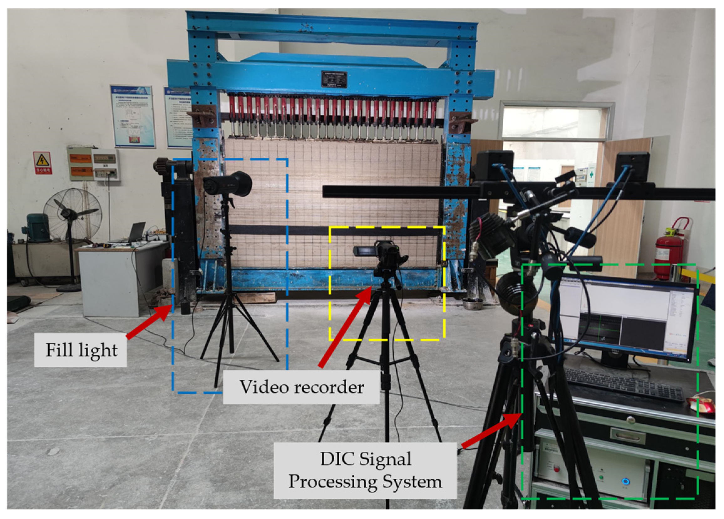
3.2.1. Experimental Device

The test was carried out using the KD-01 plane strain test bench (Figure 2). Its main body consists of a model frame, a side baffle, a moving beam, a central console, and a pressurized oil pump. The testing machine is equipped with several hydraulic loading heads, which can realize the loading function in the vertical direction (a load of 0.1–1.0 MPa can be applied stably). The test bench can accommodate a similar model of 2550 mm × 1500 mm × 300 mm, and the accuracy of loading deviation is less than 1%, which is able to carry out similar simulation experiments of overburden rock migration and roadway support under mining. Comprehensively considering the actual engineering stope conditions (such as the height of the caving zone, the height of the key layer, and the height of the mining face) and the size of the similar model test machine system to accommodate the model, the geometric similarity ratio of the test was determined to be 50. That is, the total height of the physical similarity model is 1500 mm, which corresponds to 75 m of the actual project, and the distance of the coal seam from the top of the model is 1000 mm, which corresponds to 50 m of the actual project. In addition, a video recorder with a resolution of 1280 × 720 was deployed in front of the model to record the whole test process. Based on the captured deformation and fracture images of overburden rock, the digital image correlation (DIC) signal acquisition system [56,57] was used to analyze and calculate the deformation field and displacement field of overburden rock.

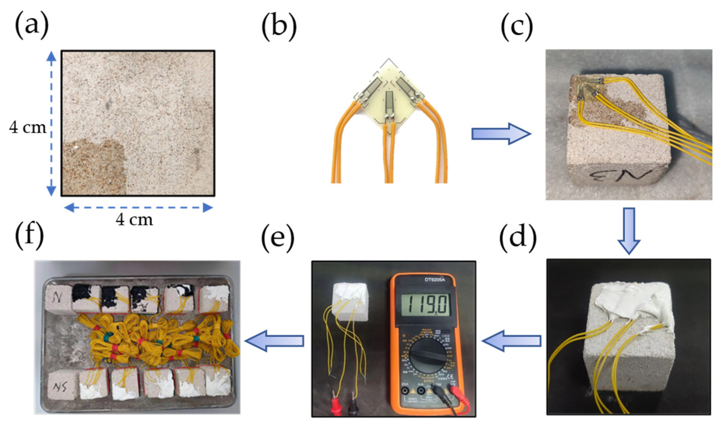
3.2.2. Similar Materials for the Model

The selection of similar materials directly affects the failure pattern and the collapse characteristics of the physical similarity model. Therefore, it is particularly important to select suitable materials with similar proportions, which is directly related to the final results of the test. However, blindly pursuing the perfect similarity between similar materials and prototypes will violate the starting point of similarity test simplification. The selection of actual similar materials should meet the similarity requirements as far as possible in terms of Poisson’s ratio, stress–strain response characteristics, material strength, and other major mechanical properties.
Referring to the research experience of previous scholars in similar rock materials, the experimental design selects fine sand, barite powder, talcum powder, and cement (32.5 ordinary silicates) as the main components for preparing similar materials for each stratum [58,59]. Among these, fine sand and barite powder as aggregates can effectively improve the overall strength of similar materials; the cement has a strong bonding force, which can effectively improve the bonding strength of the material. In addition to acting as fine aggregate, talcum powder can also effectively adjust the friction angle and other parameters of similar materials. In order to prepare similar materials for different strata that meet the test requirements, a large number of similar material preparation work was carried out before the model test. Physical and mechanical tests were carried out on similar material samples with different proportions (mainly testing their compressive and tensile strength, uniaxial compression and Brazilian fracture tests were carried out, respectively). In the orthogonal matching ratio test, the change in the average density of similar samples caused by the change in the ratio was small. Finally, the average density of similar materials was determined to be 2441.64 kg/m3, while the actual weighted average density of strata was 2551.99 kg/m3. The bulk density similarity ratio Cρ = 1.045 can be calculated. Then the stress similarity ratio of the model is determined to be 52.26. The mechanical properties are compared to determine the mix ratio of similar materials in each rock stratum. The physical and mechanical parameters of similar materials in each rock stratum of the model are shown in Table 3.

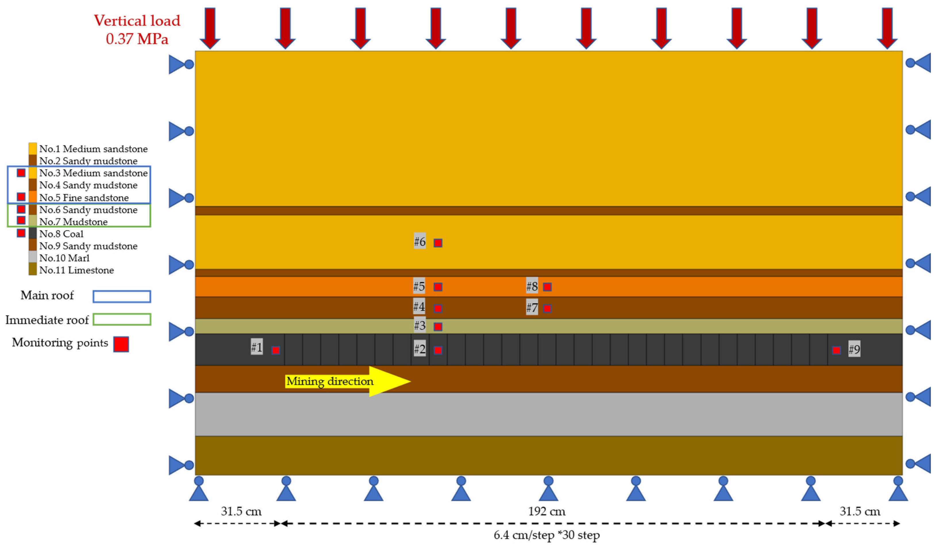
3.2.3. Model Stress Response Monitoring Method and Excavation Process

The stress response of the overlying rock was collected by means of a strain brick connected by means of a strain brick connected strain collecting instrument. The arrangement of strain bricks is shown in Figure 3. A total of nine measuring points is arranged, which are buried in coal seam (No. 8), mudstone of immediate roof (No. 7), sandy mudstone of immediate roof (No. 6), fine sandstone of main roof (No. 5), and medium sandstone of main roof (No. 3). The preparation process of the strain brick is as shown in Figure 4. The cubic similar material sample with a side length of 4 cm was prepared by using the similar mix ratio corresponding to the layer where the measuring point was located. The substrate was applied on the strain brick to enhance the contact effect between the strain brick and the strain gauge, and then the BMB120-3CA strain gauge was pasted on the strain brick. Then the waterproof adhesive was applied to prevent the strain brick from short-circuiting due to moisture, and the resistance value was measured to determine that the strain gauges were working properly before connecting the extension leads.
After the model was laid, an equivalent load of 0.37 MPa was applied to the top of the model through the upper hydraulic system (the equivalent compensated stratigraphic load with a thickness of 750 m was about 19.14 MPa, with a stress similarity ratio of 52.26). After the initial stability of the stress, the mining was carried out gradually along the direction shown in Figure 3. The open-off cut was selected at 31.50 cm on the left side of the model to eliminate the possible influence of boundary effect on the results. Then, 6.40 cm was taken as the excavation step of each time, i.e., the excavation was carried out gradually at a rate of 6.40 cm every 3.39 h, which corresponds to a daily excavation rate of 3.20 m in the actual project.

4. Result Analysis

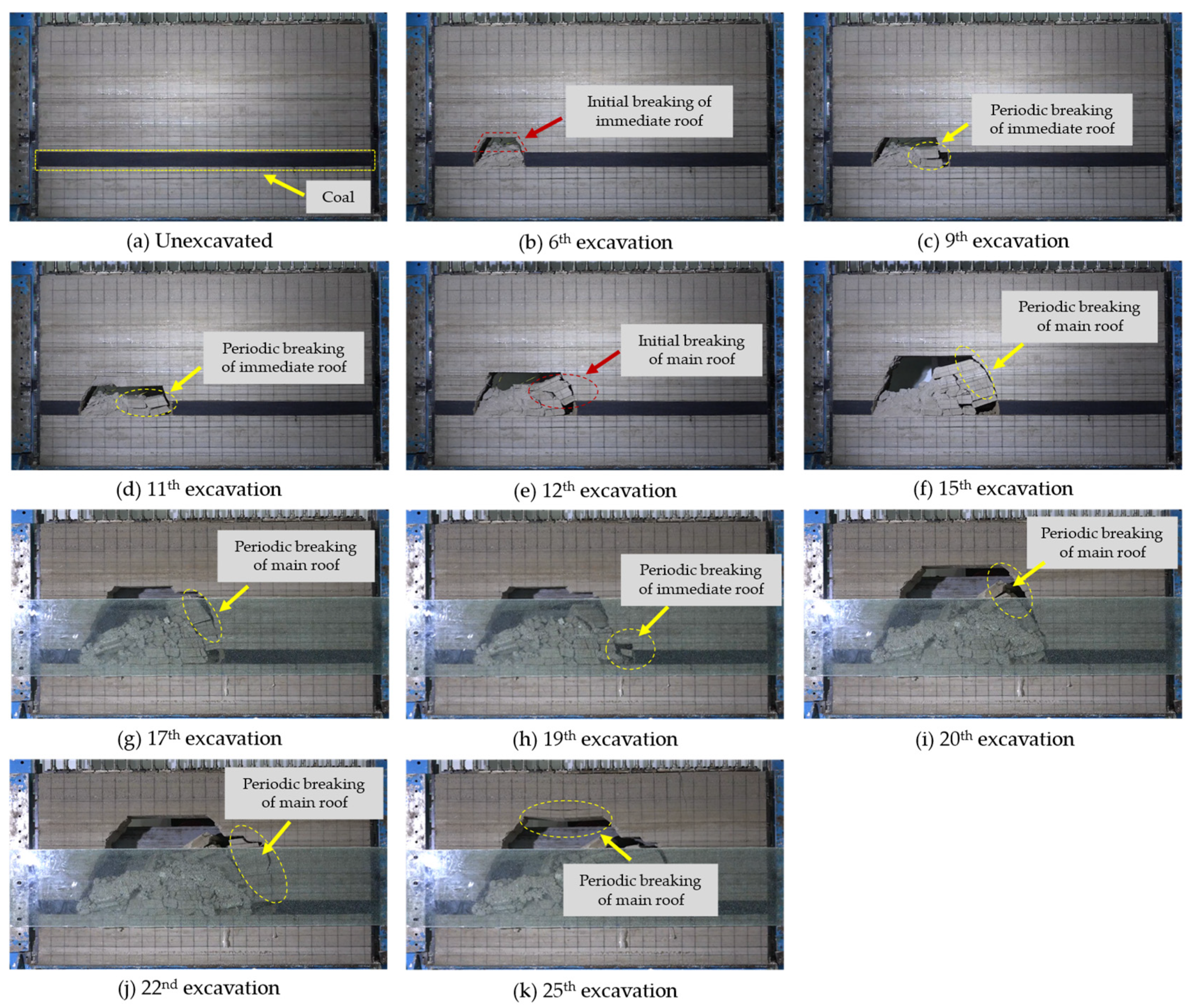
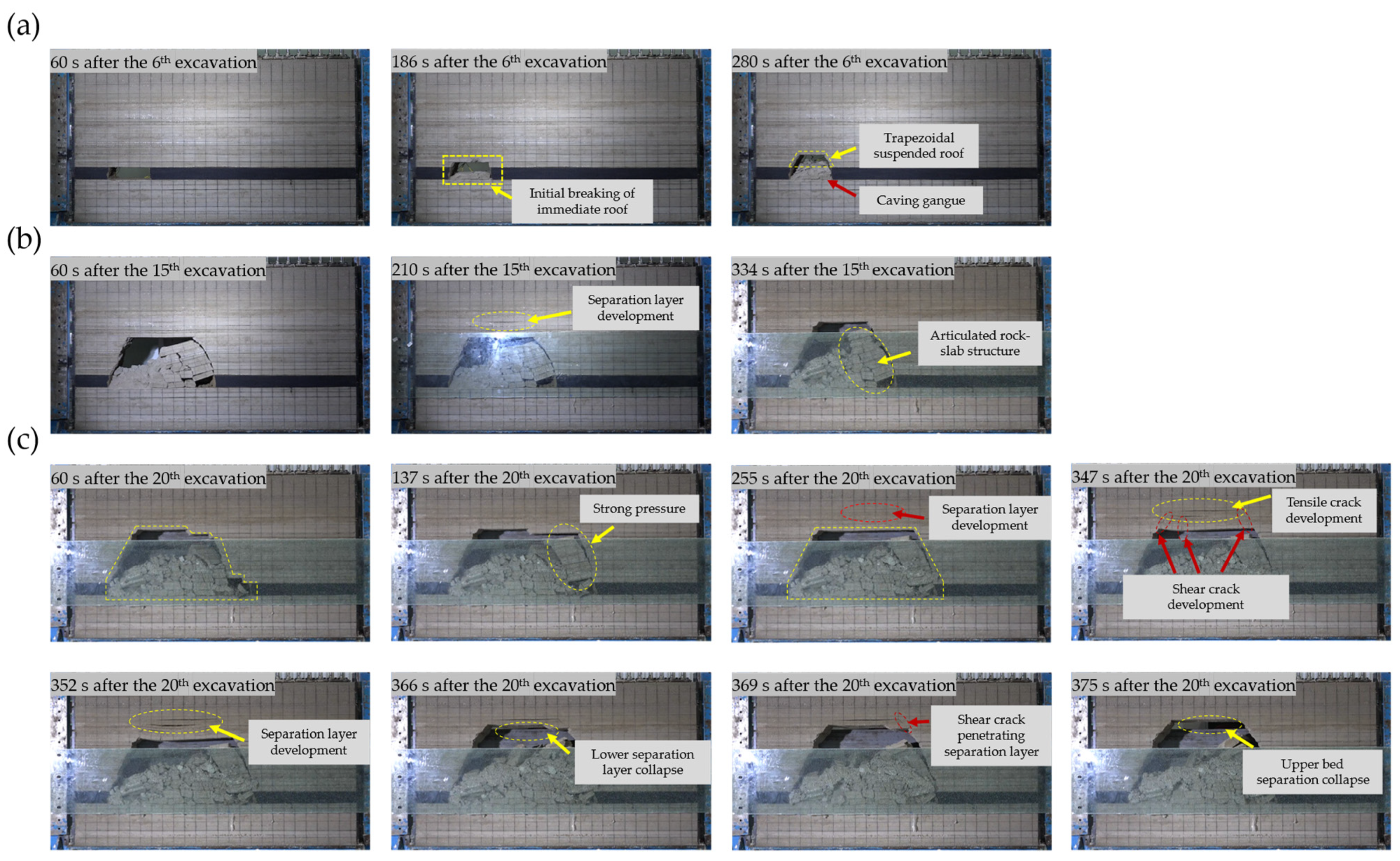
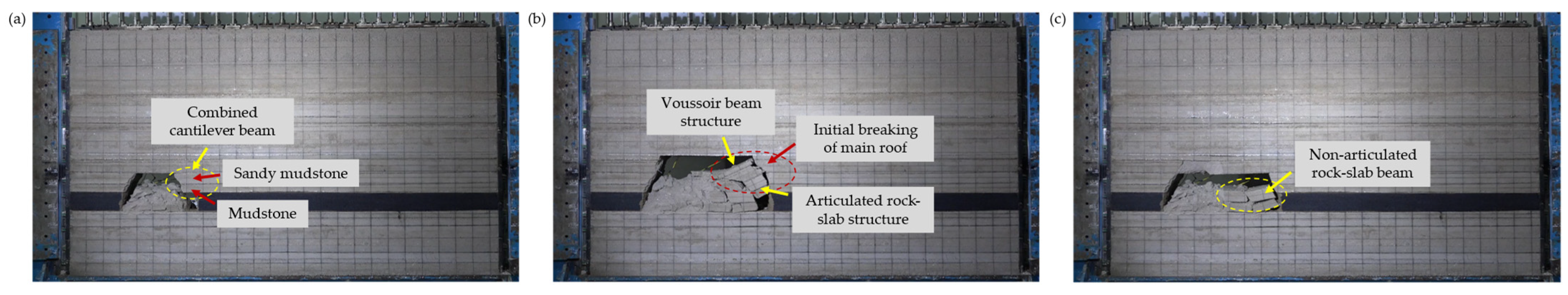
4.1. The Breaking Characteristics of the Immediate Roof and Main Roof

Figure 5 shows the process of periodic breakage of the overburden rock of the deep large-height working face during excavation. In the sixth excavation (corresponding to the actual project of 19.20 m), the first breakage of the immediate roof of the working face occurred as shown in Figure 5a. Subsequently, the periodic breakage of the immediate roof occurred in the 9th and 11th excavations, respectively. At the 12th excavation (corresponding to the actual project of 38.40 m), the main roof of the working face was broken for the first time, as shown in Figure 5e. When the working face was advanced to 48 m (Figure 5f), the caving zone continued to extend upward to the junction of sandy mudstone and medium sandstone of the main roof, with the height of the collapse zone of 11.40 m. When the working face was advanced to 54.40 m (Figure 5g), the main roof broke again, the caving zone continued to expand, and the height of the caving zone increased to 16.80 m. In addition, separation development can be seen in the upper part of the main roof. It is worth noting that the caving height and the total volume of gangue caused by this overburden rock breaking are larger, which would cause stronger pressure and make the load of hydraulic support in practical engineering, especially the dynamic load caused by the fall, more intense. Compared with the breakage of the immediate roof, the falling height of the basic roof breakage is higher and the accompanying caving zone area is larger. Therefore, more attention should be paid to the roof management of the basic roof and the resistance setting of the hydraulic support in actual engineering.
In addition to good periodicity, the deformation and breakage of overburden rock in a deep large-height working face is also persistent, i.e., it does not just occur in a short period of time. Figure 6 shows the persistent deformation of overburden rock in the stage of stress rebalance after excavation. It can be seen that the breakage of overburden rock does not always fall with mining: for deep large-height working faces, the process of stress rebalancing after mining is more complicated. Under the influence of self-weight stress and internal crack development, the overburden rock breaks in the equilibrium stage. After the breakage, the stress of the overburden rock is redistributed again, and the deformation or breakage occurs until it is stabilized. This persistent deformation and breakage process is not only manifested as rupture but also in the development of the upper separation layer (e.g., Figure 6b). In addition, the breakage is also characterized by upward expansion breakage (Figure 6a) and lateral pressure breakage (Figure 6b,c).
It is worth noting that the duration of the persistent deformation of the overburden rock increases with the expansion of the working face. In Figure 6a,b, the 6th excavation and the 15th excavation stopped obvious deformation or breakage after 280 s and 334 s of excavation, respectively. The persistent deformation of the overburden rock in the 20th excavation lasted longer, and the deformation and structural evolution of the overburden rock were more complicated (Figure 6c). The immediate roof and the main roof were broken at the same time to form strong pressure at 137 s. When the deformation of overburden rock evolves to 255 s, the structure of the stope evolves from an inverted step to a trapezoidal shape, and the separation layer is formed in the upper part of the goaf. At 347 s, the separation layer continues to develop and expand, and the hanging top at the lower part of the separation layer germinates the shear crack, which is mainly concentrated at the tip of the tensional crack of the separation layer. After the separation layer germinated, the opening of the separation layer continued to increase. At 366 s, the lower strata of the separation layer broke, and at 375 s. The upper part of the separation layer also broke and reached equilibrium again.

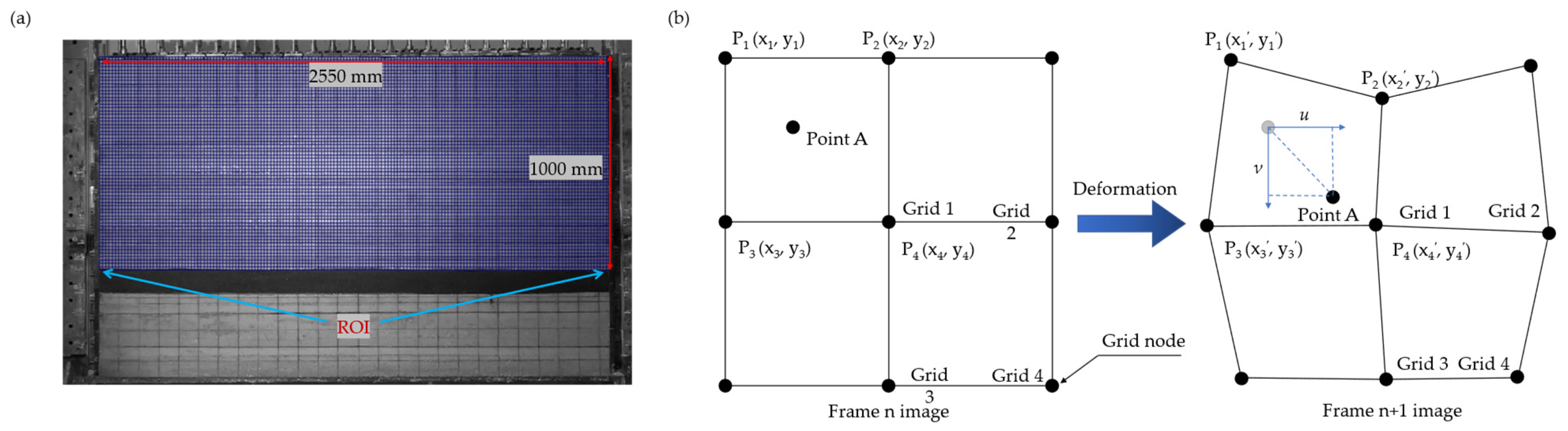
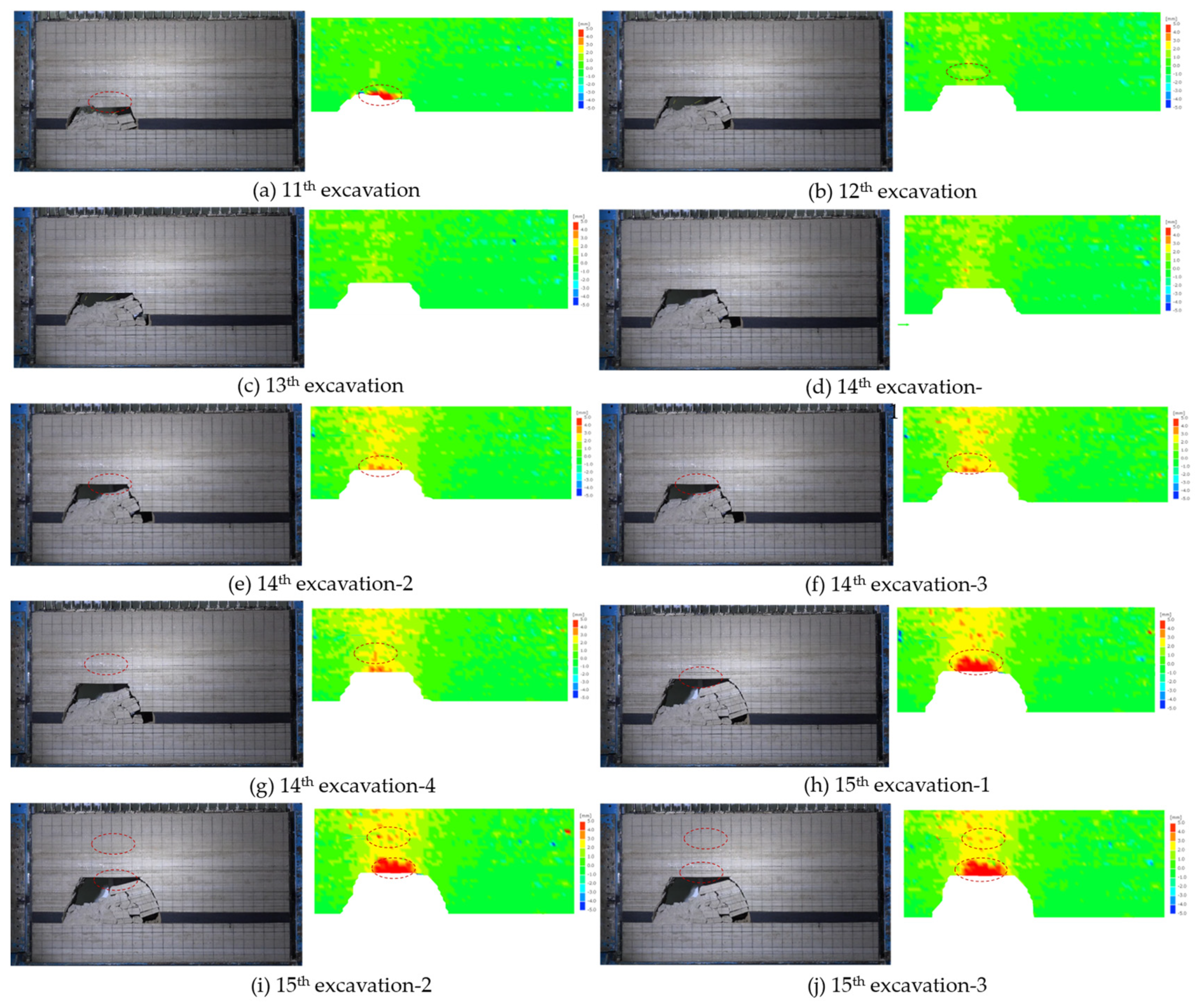
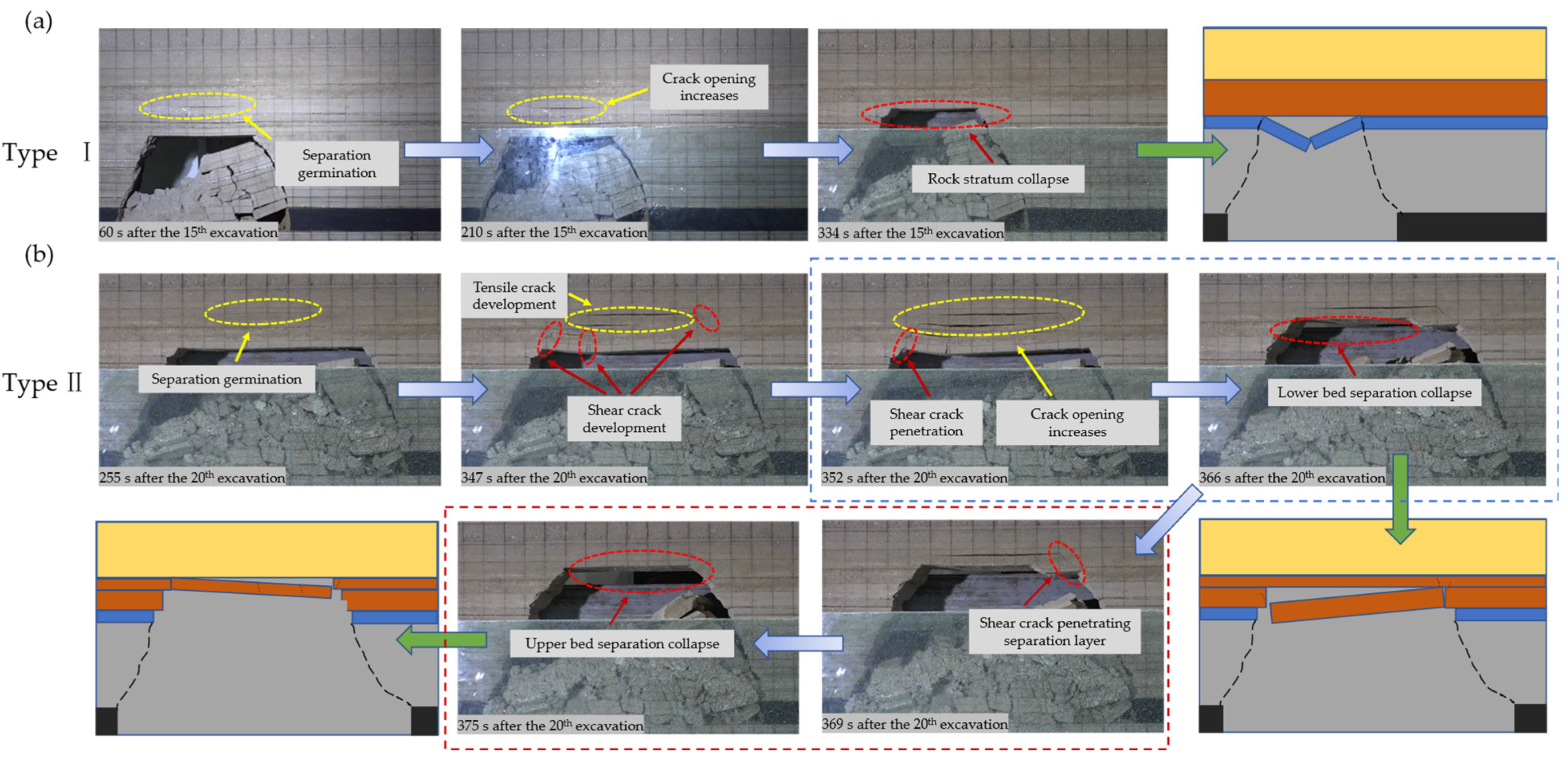
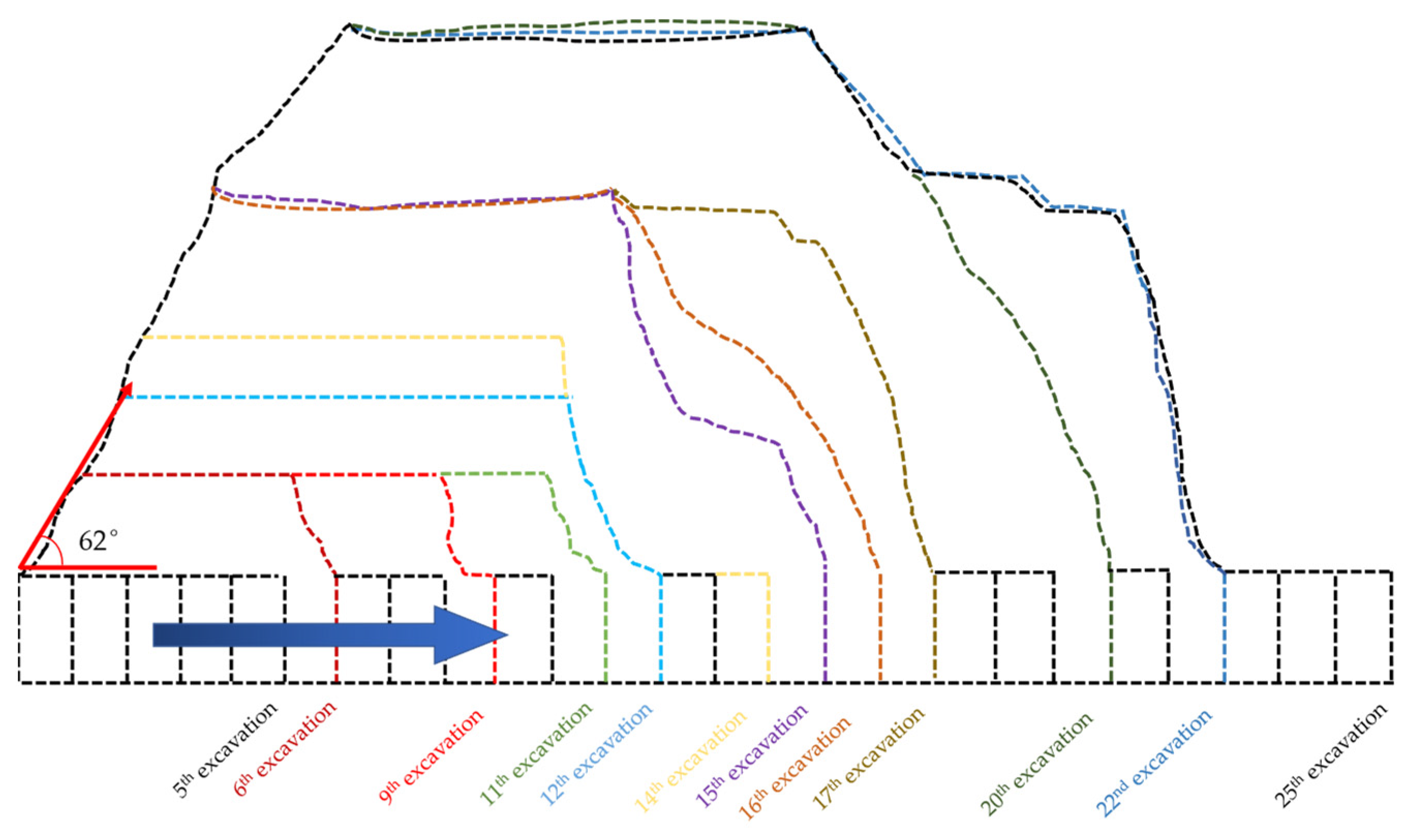
4.2. Overburden Deformation Law Based on DIC

It is clear from the above that the breakage of overburden rock is caused by the accumulation of continuous deformation. However, the persistent deformation of overburden rock is often unable to be measured directly. Therefore, this work used the DIC method to quantitatively measure the deformation characteristics of overburden rock under mining action: vertical displacement field. The overburden rock in the upper part of the coal seam was the region of interest (ROI: 2550 mm × 1000 mm). By setting the seed points and tracking the speckle image of the object surface, the measurement of the two-dimensional coordinates, displacement, and strain of the object surface during the deformation process was realized [60,61,62], as shown in Figure 7.
Figure 8 is the vertical displacement cloud diagram of overburden rock under the mining action of the physical similarity model of deep large-height working face (the 11th to 15th excavation is selected as the object). It can be seen that the overburden rock in the goaf presents subsidence migration as a whole. With the advance of the mining face, the deformation and caving area of the overburden rock expands longitudinally and horizontally, and the deformation and caving characteristics of the overburden rock also change. The deformation of overburden rock in the early stage of mining is mainly concentrated in the rock mass in the immediate roof. With the expansion of the caving zone, the deformation zone of the overburden rock extends to the main roof and the upper strata. And uneven deformation occurs in the overburden. The uncoordinated deformation of the rock stratum occurs, and the uncoordinated deformation of the upper and lower overburden rock germinates the separation layer. The main breakage forms of overburden rock can be divided into two categories according to the deformation characteristics. (I) Non-separation-induced type: mainly occurs in the immediate roof, large deformation occurs first at the exposed roof of the overburden rock, and suddenly collapses after developing to a certain extent as shown in Figure 8a. (II) Separation-induced type: mainly occurs in the main roof, the deformation of the upper and lower strata is not coordinated along the weak surface to develop the separation layer. Separation weakens the stability of the lower rock mass, which in turn induces the collapse of the overburden rock, as shown in Figure 8g–j.

4.3. Structural Evolutionary Characteristics of Deep Large Mining Height Quarries

The evolution characteristics of the overburden rock structure have an important influence on the mine pressure behavior. The breakage characteristics such as when the roof breaks, where the roof breaks, and the volume of the broken overlying rock have important guiding significance for the setting of the support parameters of the working face. These breakage characteristics are often affected by the structural characteristics of overburden rock, and the breakage characteristics under different overburden rock structures are often regular. As pointed out above, separation layer development often occurs in the main roof.
Furthermore, the forms of separation-induced breakage can be categorized into two types: (i) Dominated by self-weight stress, the breakage occurs at the maximum deflection in the middle of the rock plate, as shown in Figure 9a. (ii) Under the influence of shear cracks, the crack penetrates through the separation layer along the fracture slip surface, and the breakage occurs on both sides of the rock plate. For example, during the 20th excavation disturbance (Figure 9b), the separation-induced breakage affected by shear cracks occurred in the overburden rock. At 255 s, the upper part of the roof was separated. At 347 s, the separation layer develops, the opening increases, and many shear cracks develop on both wings of the separation layer. At 352 s, the left shear crack runs through the lower rock plate of the separation layer along the extension direction of the fracture line of the stope. At 366 s, the lower rock plate of the separation layer is broken. At 369 s, the shear crack on the right side also penetrated the upper rock plate and broke at 375 s, and the overburden rock of the stope reached the equilibrium state again.
To further understand the evolution characteristics of the mining field structure of the deep large-height working face, the sketch map of the stope structure outline under mining is drawn as Figure 10. From the shape of the upper structure of the stope: from the rectangular shape when the collapse did not occur to the trapezoidal shape at the initial stage of the collapse, and then to the multi-stepped trapezoidal shape of the main roof collapse. The change of its main body shape mainly depends on the fracture line shape from the advancing side coal wall to the upper overburden rock: there is an oblique straight line at the initial stage of mining, an arc shape when the main roof is broken, and a multi-stage step shape formed along the combined cantilever beam. The extension of the fracture line will affect the collapse of the overlying strata on the upper part of the hydraulic support and the transportation belt in actual production. For example, the shear crack in Figure 9 germinates between the separation layer and the fracture line, and penetrates the bed separation in the subsequent stage, resulting in the collapse of the rock mass below the bed separation.
From the distribution of overburden structure form: the overburden structure of the 12,110 deep large mining height working face presents a “combined cantilever beam structure-articulated rock-slab structure-non-articulated rock-slab structure”. From the top to the bottom, it is mainly distributed by combined cantilever beam structure, articulated rock-slab structure, and non-articulated rock-slab structure, as shown in Figure 11. Among them, the periodic breaking of the upper cantilever beam evolves articulated and non-articulated rock-slab structures in the lower part, which weakens the supporting effect of the lower gangue and further aggravates the upper overburden breaking. Combined with the structural distribution of overburden rock in Figure 5 and Figure 6, it can be concluded that the combined cantilever beam structure and non-articulated rock-slab structure are the main structural forms of overburden rock on the advancing side of the working face, while the articulated rock-slab structure is mainly concentrated between the caving gangue area and the roof strata on the advancing side, which directly affects the mine pressure appearance of the working face. The periodic breakage of the non-articulated roof structure produces less periodic pressure on the working face hydraulic support in actual production.

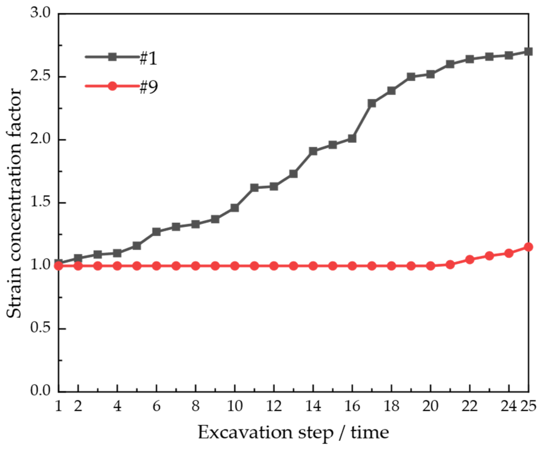
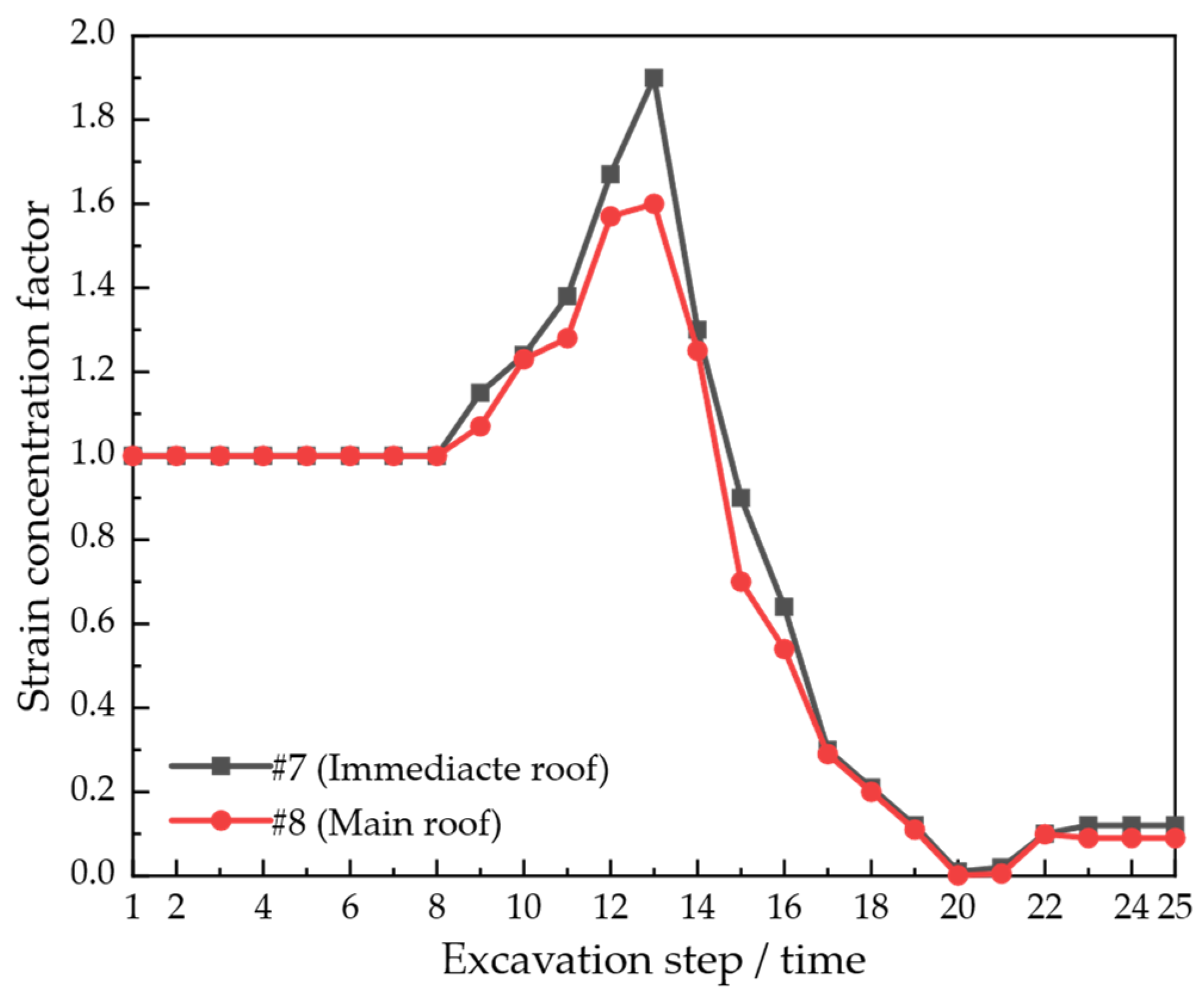
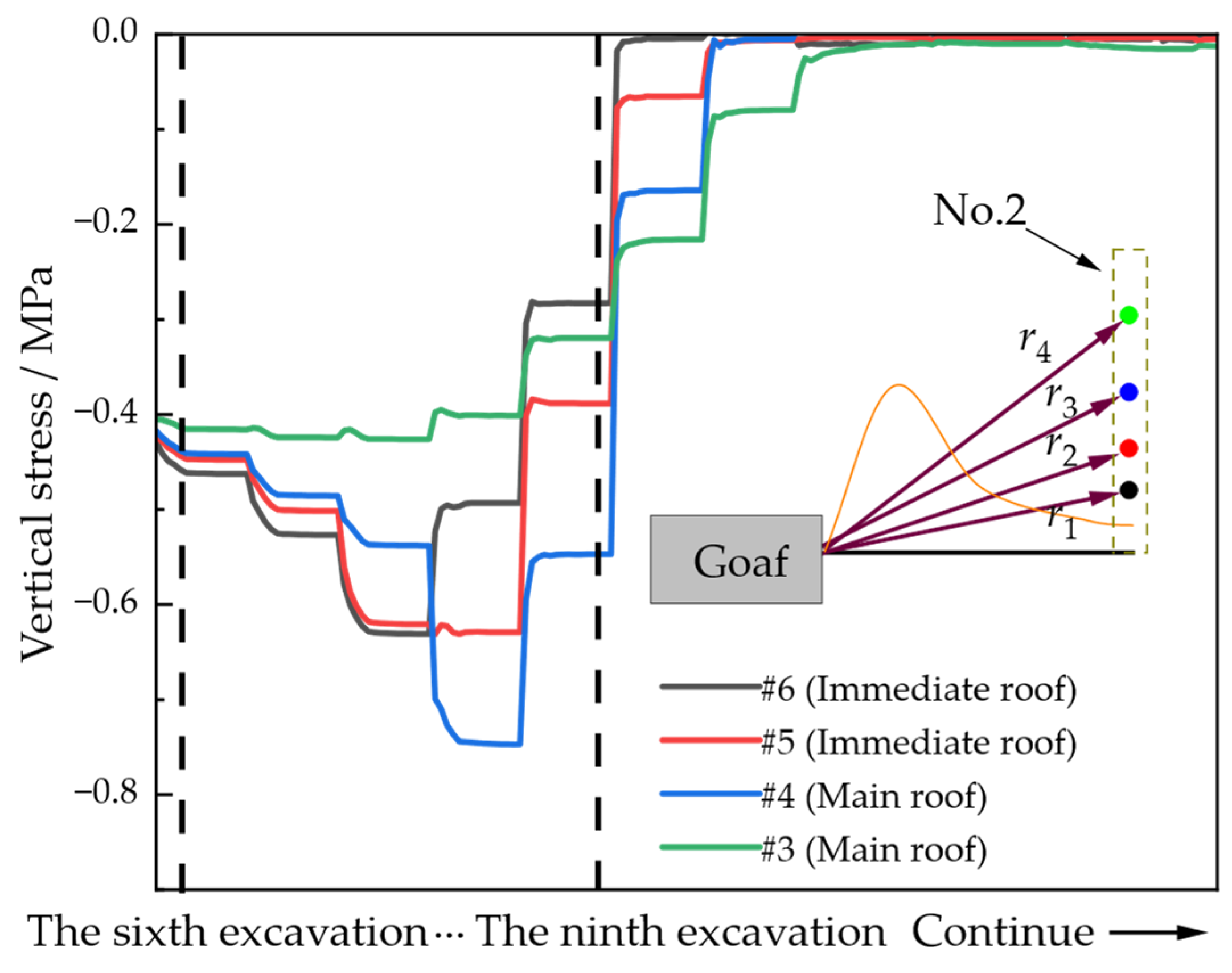
4.4. Mineral Pressure Manifestation Characteristics of Deep Large Mining Face

Coal seam mining activities destroy the equilibrium state of the initial stress field of the surrounding rock near the working face, causing the stress redistribution of the surrounding rock mass: either deformation or breakage occurs, and then reaches the equilibrium state again. In other words, the change of overburden structure causes the change of stress, and the change of stress induces the change of overburden structure, which is manifested as mine pressure at the working face. The small changes in the structure of overburden structure are difficult to observe by the naked eye. Therefore, scholars study the structural stability of the stope by studying the stress evolution of the stope.
To further study the characteristics of mine pressure behavior in deep large-height working faces, the stress change process in overburden rock under mining is monitored. Figure 12 shows the change trend diagram of the stress concentration coefficient of measuring points in coal pillars on both sides under mining. The abscissa is the number of excavations, that is, the excavation step. The longitudinal axis is the stress concentration coefficient, and the stress coefficient is the ratio of the stress value after the disturbance to the original rock stress. It can effectively characterize the degree of stress rise and fall at different measuring points. According to the monitoring results of overburden rock stress, since there is no obvious compaction area in this physical similarity model, one arch foot of the pressure arch is always inside the left coal wall. The stress at the measuring point of the left coal pillar of the coal seam always keeps rising during the 25th working face advancement, and the overall relationship is proportional. When the roof breaks, the structure in the pressure arch changes, the stress concentration factor increases greatly, and the stress concentration is more obvious. When the span of goaf increases to a certain range, the increase in stress concentration factor slows down. Among these, when the excavation time is 22, the stress at the measuring point of the coal pillar on the right side of the coal seam begins to rise, and the measuring point position enters the influence area of the abutment pressure zone. The horizontal distance is 28.8 m, which is in good agreement with the measured advance pressure range of 30.0 m.
To study the typical stress change trend of overburden rock, another measuring point was selected in the immediate roof and the main roof, respectively. As shown in Figure 13, the initial mining of the coal seam has no obvious effect on the overburden rock at the far end of the measuring point. When the working face advances, the advanced pressure affected zone moves forward, and the stress state of the overburden rock at the measuring point changes, showing an upward trend. When the working face advances to the area near the measuring point, the stress concentration coefficient reaches the maximum value. When the working face continues to excavate, the overburden rock at the measuring point enters the range of pressure arch successively, the stress relaxes, the stress concentration coefficient begins to decrease, and the stress at the measuring point decreases rapidly. At this time, the overburden rock is more likely to loosen and break under the influence of self-weight stress. In particular, the maximum value of the stress concentration factor of the upper overburden is relatively small compared with that of the lower overburden, and the increase in the stress concentration factor caused by the recompaction of the gangue is also small.
To further analyze the difference in stress response between upper and lower rock layers, a set of measuring points of upper and lower rock layers were selected, as shown in Figure 14. The mudstone layer in the lower part of the immediate roof is closest to the goaf, which is first affected by the disturbance and the stress rises. However, the medium sandstone in the upper part of the main roof is far away from the mining coal seam, and only a slight stress rise occurs. As the working face advances, it enters the pressure arch and the compressive stress decreases. In theory, the point closest to the mining surface first increases the compressive stress, and the stress concentration coefficient of the compressive stress is the largest. However, in the actual evolution process of overburden structure, the mudstone layer and sandy mudstone layer in the immediate roof form a combined cantilever beam suspended in the upper part of the goaf, which makes the stress concentration coefficient reach the maximum in the fine sandstone of the main roof.

5. Conclusions

In this work, the physical modeling test was carried out on the basis of obtaining the physical and mechanical parameters of the overburden rock of a deep large-height mining face in Pingdingshan Coal Mine as an example. The collapse characteristics of overburden rock during the mining of the deep large-height working face were studied, and the migration and deformation characteristics of overburden rock were investigated by means of the digital image correlation (DIC) method. On this basis, the distribution and evolution characteristics of overburden structures in deep large-height working faces were summarized. In addition, the evolution characteristics of stress distribution of overburden rock were studied. The main conclusions are as follows:
(1) The breakage of overburden rock in the mining process of the deep large-height working face is cyclical. The deformation and breakage of overburden rock are persistent, not only occurring over a short period of time. The duration of the persistent deformation of overburden rock increases with the expansion of the working face. The 6th and 15th excavations stopped obvious deformation or breakage after 280 s and 334 s, respectively. The duration of persistent deformation of the overburden in the 20th excavation is longer, and the deformation and structural evolution of the overburden are more complicated.
(2) The form of breakage of overburden rock can be divided into two categories according to the deformation characteristics: (I) Non-separation-induced type: which mainly occurs in the immediate roof. Large deformation occurs first at the exposed overburden roof and suddenly collapses after development to a certain extent. (II) Separation-induced type: which mainly occurs in the basic roof, the deformation of the upper and lower rock layers is not coordinated, and the separation is developed along the weak surface. Separation weakens the stability of the lower rock mass, which in turn induces the collapse of the overburden rock. Among these, the breakage induced by separation can be divided into two categories: (i) dominated by self-weight stress, and (ii) affected by shear crack.
(3) The structural morphology of the upper part of the stope: from the rectangular form when no collapse occurred, to the trapezoidal form at the early stage of collapse, and then to the multi-stepped trapezoidal form after the collapse of the basic roof. The change of its main form mainly depends on the fracture line form from the coal wall on the advancing side to the overburden rock on the upper part: there is an oblique straight line at the initial stage of mining, an arc shape when the main roof breaks down, and a multi-stage step shape formed along the combined cantilever beam.
(4) From the distribution of overburden structure form, the overburden structure presents “combined cantilever beam structure-articulated rock-slab structure-non-articulated rock-slab structure”. Among them, the periodic breaking of the upper cantilever beam evolves into articulated and non-articulated rock-slab structures in the lower part, which weakens the supporting effect of the lower gangue and further aggravates the upper overburden breaking.

Author Contributions

Conceptualization, J.Z. and X.Q.; Methodology, X.Q. and H.S.; Software, X.Q.; Formal analysis, J.Z.; Investigation, J.Z., S.L. and Z.Y.; Resources, G.Z.; Writing—original draft, J.Z.; Writing—review and editing, X.Q.; Supervision, X.Q., Z.Y. and G.Z.; Project administration, J.Z. and S.L.; Funding acquisition, H.S. All authors have read and agreed to the published version of the manuscript.

Funding

This work was supported by the Open Research Fund of State Key Laboratory of Coking Coal Exploitation and Comprehensive Utilization, China Pingmei Shenma Group, Grant NO. 41040220201308.

Data Availability Statement

The data used to support the findings of this study are available from the corresponding author upon request.

Conflicts of Interest

The authors declare that they have no competing interests or personal relationships that could have appeared to influence the work reported in this paper.

References

  1. Yi, S.; Abbasi, K.R.; Hussain, K.; Albaker, A.; Alvarado, R. Environmental concerns in the United States: Can renewable energy, fossil fuel energy, and natural resources depletion help? Gondwana Res. 2023, 117, 41–55. [Google Scholar] [CrossRef]
  2. Rehman, A.; Ma, H.Y.; Ozturk, I.; Radulescu, M. Revealing the dynamic effects of fossil fuel energy, nuclear energy, renewable energy, and carbon emissions on Pakistan’s economic growth. Environ. Sci. Pollut. Res. 2022, 29, 48784–48794. [Google Scholar] [CrossRef] [PubMed]
  3. Su, F.; Chang, J.B.; Li, X.; Fahad, S.; Ozturk, I. Assessment of diverse energy consumption structure and social capital: A case of southern Shaanxi province China. Energy 2023, 262, 125506. [Google Scholar] [CrossRef]
  4. Xu, J.H.; Kang, Y.; Wang, X.C.; Feng, G.; Wang, Z.F. Dynamic characteristics and safety criterion of deep rock mine opening under blast loading. Int. J. Rock Mech. Min. Sci. 2019, 119, 156–167. [Google Scholar] [CrossRef]
  5. He, M.C.; Cheng, T.; Qiao, Y.F.; Li, H.R. A review of rockburst: Experiments, theories, and simulations. J. Rock Mech. Geotech. Eng. 2023, 15, 1312–1353. [Google Scholar] [CrossRef]
  6. Yang, D.D.; Peng, K.; Zheng, Y.; Chen, Y.J.; Zheng, J.; Wang, M.; Chen, S. Study on the characteristics of coal and gas outburst hazard under the influence of high formation temperature in deep mines. Energy 2023, 268, 126645. [Google Scholar] [CrossRef]
  7. Wang, L.; Lu, Z.; Chen, D.P.; Liu, Q.Q.; Chu, P.; Shu, L.Y.; Ullah, B.; Wen, Z.J. Safe strategy for coal and gas outburst prevention in deep-and-thick coal seams using a soft rock protective layer mining. Saf. Sci. 2020, 129, 104800. [Google Scholar] [CrossRef]
  8. Xia, B.W.; Jia, J.L.; Yu, B.; Zhang, X.; Li, X.L. Coupling effects of coal pillars of thick coal seams in large-space stopes and hard stratum on mine pressure. Int. J. Min. Sci. Technol. 2017, 27, 965–972. [Google Scholar] [CrossRef]
  9. Zhang, Q.; Zhang, J.X.; Kang, T.; Sun, Q.; Li, W.K. Mining pressure monitoring and analysis in fully mechanized backfilling coal mining face-A case study in Zhai Zhen Coal Mine. J. Cent. South Univ. 2015, 22, 1965–1972. [Google Scholar] [CrossRef]
  10. Xie, S.R.; Pan, H.; Zeng, J.C.; Wang, E.; Chen, D.D.; Zhang, T.; Peng, X.J.; Yang, J.H.; Chen, F.; Qiao, S.X. A case study on control technology of surrounding rock of a large section chamber under a 1200-m deep goaf in Xingdong coal mine, China. Eng. Fail. Anal. 2019, 104, 112–125. [Google Scholar] [CrossRef]
  11. Zhao, C.X.; Li, Y.M.; Liu, G.; Meng, X.R. Mechanism analysis and control technology of surrounding rock failure in deep soft rock roadway. Eng. Fail. Anal. 2020, 115, 104611. [Google Scholar] [CrossRef]
  12. He, M.C.; Wang, Q. Excavation compensation method and key technology for surrounding rock control. Eng. Geol. 2022, 307, 106784. [Google Scholar] [CrossRef]
  13. Xie, Z.Z.; Zhang, N.; Feng, X.W.; Liang, D.X.; Wei, Q.; Weng, M.Y. Investigation on the evolution and control of surrounding rock fracture under different supporting conditions in deep roadway during excavation period. Int. J. Rock Mech. Min. Sci. 2019, 123, 104122. [Google Scholar] [CrossRef]
  14. Poulsen, B.A. Coal pillar load calculation by pressure arch theory and near field extraction ratio. Int. J. Rock Mech. Min. Sci. 2010, 47, 1158–1165. [Google Scholar] [CrossRef]
  15. Li, C.C.L. Rock support design based on the concept of pressure arch. Int. J. Rock Mech. Min. Sci. 2006, 43, 1083–1090. [Google Scholar] [CrossRef]
  16. Li, X.Y.; Chen, P.H. Study on regularity of structural behaviours around coal face under the shallow-buried loose roof. Chin. J. Rock Mech. Eng. 2004, 2004, 3305–3309. [Google Scholar]
  17. Diederichs, M.S.; Kaiser, P.K. Stability of large excavations in laminated hard rock masses: The voussoir analogue revisited. Int. J. Rock Mech. Min. Sci. 1999, 36, 97–117. [Google Scholar] [CrossRef]
  18. Li, C.C. Principles of rockbolting design. J. Rock Mech. Geotech. Eng. 2017, 9, 396–414. [Google Scholar] [CrossRef]
  19. Xie, G.X.; Chang, J.C.; Yang, K. Investigations into stress shell characteristics of surrounding rock in fully mechanized top-coal caving face. Int. J. Rock Mech. Min. Sci. 2009, 46, 172–181. [Google Scholar] [CrossRef]
  20. Zhu, C.; Yuan, Y.; Wang, W.M.; Chen, Z.S.; Wang, S.Z.; Zhong, H.W. Research on the “three shells” cooperative support technology of large-section chambers in deep mines. Int. J. Min. Sci. Technol. 2021, 31, 665–680. [Google Scholar] [CrossRef]
  21. Lv, H.Y.; Cheng, Z.B.; Liu, F. Study on the mechanism of a new fully mechanical mining method for extremely thick coal seam. Int. J. Rock Mech. Min. Sci. 2021, 142, 104788. [Google Scholar] [CrossRef]
  22. He, M.C.; Zhu, G.L.; Guo, Z.B. Longwall mining “cutting cantilever beam theory” and 110 mining method in China-The third mining science innovation. J. Rock Mech. Geotech. Eng. 2015, 7, 483–492. [Google Scholar] [CrossRef]
  23. Qian, M.G. The equilibrium condition for overlying strata in the stope. J. China Univ. Min. Technol. 1981, 2, 31–40. [Google Scholar]
  24. Qian, M.G. The structural model of overlying strata in the stope and its application. J. China Univ. Min. Technol. 1982, 2, 1–11. [Google Scholar]
  25. Song, Z.Q. Basic rules for stope overlying strata. J. Shandong Inst. Min. Technol. 1979, 1, 12–25. [Google Scholar]
  26. Song, Z.Q. Rules for the stope bearing pressure and its application. J. Shandong Inst. Min. Technol. 1982, 1, 1–25. [Google Scholar]
  27. Yu, Y.X.; Huang, R.B.; Wang, B.Q. Analysis on limit equilibrium zone of coal pillar in mining roadway based on mechanical model of elastic foundation beam. J. Eng. Mech. 2016, 142, 04016009. [Google Scholar] [CrossRef]
  28. Wang, P.; Jiang, J.Q.; Zhang, P.P.; Wu, Q.L. Breaking process and mining stress evolution characteristics of a high-position hard and thick stratum. Int. J. Min. Sci. Technol. 2016, 26, 563–569. [Google Scholar] [CrossRef]
  29. Huang, P.; Zhang, J.X.; Yan, X.J.; Spearing, A.J.S.; Li, M.; Liu, S.W. Deformation response of roof in solid backfilling coal mining based on viscoelastic properties of waste gangue. Int. J. Min. Sci. Technol. 2021, 31, 279–289. [Google Scholar] [CrossRef]
  30. Yang, Z.Q.; Liu, C.; Zhu, H.Z.; Xie, F.X.; Dou, L.M.; Chen, J.H. Mechanism of rock burst caused by fracture of key strata during irregular working face mining and its prevention methods. Int. J. Min. Sci. Technol. 2019, 29, 889–897. [Google Scholar] [CrossRef]
  31. Peng, K.; Yin, X.Y.; Yin, G.Z.; Xu, J.; Huang, G.; Yin, Z.Q. Galerkin solution of Winkler foundation-based irregular Kirchhoff plate model and its application in crown pillar optimization. J. Cent. South Univ. 2016, 23, 1253–1263. [Google Scholar] [CrossRef]
  32. Bui, T.Q.; Nguyen, T.N.; Nguyen-Dang, H. A moving Kriging interpolation-based meshless method for numerical simulation of Kirchhoff plate problems. Int. J. Numer. Meth. Eng. 2009, 77, 1371–1395. [Google Scholar] [CrossRef]
  33. Meng, Q.B.; Han, L.J.; Xiao, Y.; Li, H.; Wen, S.Y.; Zhang, J. Numerical simulation study of the failure evolution process and failure mode of surrounding rock in deep soft rock roadways. Int. J. Min. Sci. Technol. 2016, 26, 209–221. [Google Scholar] [CrossRef]
  34. Cheng, G.; Xu, W.T.; Shi, B.; Wu, J.H.; Sun, B.Y.; Zhu, H.H. Experimental study on the deformation and failure mechanism of overburden rock during coal mining using a comprehensive intelligent sensing method. J. Rock Mech. Geotech. Eng. 2022, 14, 1626–1641. [Google Scholar] [CrossRef]
  35. Zhu, G.A.; Dou, L.M.; Liu, Y.; Su, Z.G.; Li, H. Rock burst mechanism analysis on deep irregular island face. J. Min. Saf. Eng. 2016, 33, 63–635. [Google Scholar]
  36. He, L.; Zhang, Q.B. Numerical investigation of arching mechanism to underground excavation in jointed rock mass. Tunn. Undergr. Space Technol. 2015, 50, 54–67. [Google Scholar] [CrossRef]
  37. Li, Y.Y.; Zhang, S.C.; Gao, L.Q.; Kong, D.Z.; Kong, H. Mechanism and prevention of pressure burst in step region based on overburden strata movement of unequal length working face. Rock Soil Mech. 2016, 37, 3283–3290. [Google Scholar]
  38. Li, Y.L.; Yang, R.S.; Fang, S.Z.; Lin, H.; Lu, S.J.; Zhu, Y.; Wang, M.S. Failure analysis and control measures of deep roadway with composite roof: A case study. Int. J. Coal Sci. Technol. 2022, 9, 2. [Google Scholar] [CrossRef]
  39. Kong, D.Z.; Xiong, Y.; Cheng, Z.B.; Wang, N.; Wu, G.Y.; Liu, Y. Stability analysis of coal face based on coal face-support-roof system in steeply inclined coal seam. Geomech. Eng. 2021, 25, 233–243. [Google Scholar]
  40. Kulatilake, P.H.S.W.; Wu, Q.; Yu, Z.X.; Jiang, F.X. Investigation of stability of a tunnel in a deep coal mine in China. Int. J. Min. Sci. Technol. 2013, 23, 579–589. [Google Scholar] [CrossRef]
  41. Liang, Y.P.; Li, B.; Yuan, Y.; Zou, Q.L.; Jia, L.X. Moving type of key strata and its influence on ground pressure in fully mechanized mining face with large mining height. J. China Coal Soc. 2017, 42, 1380–1391. [Google Scholar]
  42. Xu, J.L.; Ju, Q.F. Structural morphology of key stratum and its influence on strata behaviors in fully-mechanized face with super-large mining height. Chin. J. Rock Mech. Eng. 2011, 30, 1547–1556. [Google Scholar]
  43. Li, M.; Zhang, J.X.; Huang, Y.L.; Gao, R. Measurement and numerical analysis of influence of key stratum breakage on mine pressure in top-coal caving face with super great mining height. J. Cent. South Univ. 2017, 24, 1881–1888. [Google Scholar] [CrossRef]
  44. Zhang, J.C.; Li, X.L.; Qin, Q.Z.; Wang, Y.B.; Gao, X. Study on overlying strata movement patterns and mechanisms in super-large mining height stopes. Bull. Eng. Geol. Environ. 2023, 82, 142. [Google Scholar] [CrossRef]
  45. Yin, X.W. Cutting block structure model of overburden with shallow buried coal seam and ultra-large mining height working face. J. China Coal Soc. 2019, 44, 1961–1970. [Google Scholar]
  46. Wang, J.C.; Yang, S.L.; Kong, D.Z. Failure mechanism and control technology of longwall coalface in large-cutting-height mining method. Int. J. Min. Sci. Technol. 2016, 26, 111–118. [Google Scholar] [CrossRef]
  47. Wang, Q.; Qin, Q.; Jiang, B.; Jiang, Z.H.; He, M.C.; Li, S.C.; Wang, Y. Geomechanics model test research on automatically formed roadway by roof cutting and pressure releasing. Int. J. Rock Mech. Min. Sci. 2020, 135, 104506. [Google Scholar] [CrossRef]
  48. ISRM Rock Characterization. Rock Characterization, Testing and Monitoring, ISRM Suggested Methods; Brown, E.T., Ed.; Pergamon Press: Oxford, UK, 1981. [Google Scholar]
  49. ISRM Rock Characterization. Suggested methods for determining tensile strength of rock materials. Int. J. Rock Mech. Min. Sci. Geomech. Abstr. 1978, 15, 99–103. [Google Scholar] [CrossRef]
  50. Lu, J.; Jiang, C.B.; Jin, Z.; Wang, W.S.; Zhuang, W.J.; Yu, H. Three-dimensional physical model experiment of mining-induced deformation and failure characteristics of roof and floor in deep underground coal seams. Process Saf. Environ. Prot. 2021, 150, 400–415. [Google Scholar] [CrossRef]
  51. Cao, J.C.; Zhang, N.; Wang, S.Y.; Qian, D.Y.; Xie, Z.Z. Physical model test study on support of super pre-stressed anchor in the mining engineering. Eng. Fail. Anal. 2020, 118, 104833. [Google Scholar] [CrossRef]
  52. Tao, Z.G.; Shu, Y.; Yang, X.J.; Peng, Y.Y.; Chen, Q.H.; Zhuang, H.J. Physical model test study on shear strength characteristics of slope sliding surface in Nanfen open-pit mine. Int. J. Min. Sci. Technol. 2020, 30, 421–429. [Google Scholar] [CrossRef]
  53. Jiang, W.; Xu, X.Y.; Wen, Z.H.; Wei, L. Applying the similarity theory to model dust dispersion during coal-mine tunneling. Process Saf. Environ. Prot. 2021, 148, 415–427. [Google Scholar] [CrossRef]
  54. Dehghani, H.; Ataee-pour, M. Development of a model to predict peak particle velocity in a blasting operation. Int. J. Rock Mech. Min. Sci. 2011, 48, 51–58. [Google Scholar] [CrossRef]
  55. Ye, Q.; Wang, G.; Jia, Z.Z.; Zheng, C.S.; Wang, W.J. Similarity simulation of mining-crack-evolution characteristics of overburden strata in deep coal mining with large dip. J. Petrol. Sci. Eng. 2018, 165, 477–487. [Google Scholar] [CrossRef]
  56. Xiong, X.Y.; Dai, J.; Ouyang, Y.B.; Shen, P. Experimental analysis of control technology and deformation failure mechanism of inclined coal seam roadway using non-contact DIC technique. Sci. Rep. 2021, 11, 20930. [Google Scholar] [CrossRef]
  57. Qiu, J.D.; Li, X.B.; Li, D.Y.; Zhao, Y.Z.; Hu, C.W.; Liang, L.S. Physical model test on the deformation behavior of an underground tunnel under blasting disturbance. Rock Mech. Rock Eng. 2021, 54, 91–108. [Google Scholar] [CrossRef]
  58. Xu, Z.L.; Luo, Y.B.; Chen, J.X.; Su, Z.M.; Zhu, T.T.; Yuan, J.P. Mechanical properties and reasonable proportioning of similar materials in physical model test of tunnel lining cracking. Constr. Build. Mater. 2021, 300, 123960. [Google Scholar] [CrossRef]
  59. Tian, Q.Y.; Zhang, J.T.; Zhang, Y.L. Similar simulation experiment of expressway tunnel in karst area. Constr. Build. Mater. 2018, 176, 1–13. [Google Scholar] [CrossRef]
  60. Huang, F.; Wu, C.Z.; Ni, P.P.; Wan, G.Q.; Zheng, A.C.; Jang, B.A.; Karekal, S. Experimental analysis of progressive failure behavior of rock tunnel with a fault zone using non-contact DIC technique. Int. J. Rock Mech. Min. Sci. 2020, 132, 104355. [Google Scholar] [CrossRef]
  61. Zhang, Q.B.; Zhao, J. Determination of mechanical properties and full-field strain measurements of rock material under dynamic loads. Int. J. Rock Mech. Min. Sci. 2013, 60, 423–439. [Google Scholar] [CrossRef]
  62. Gao, M.Z.; Xie, J.; Gao, Y.A.; Wang, W.Y.; Li, C.; Yang, B.G.; Liu, J.J.; Xie, H.P. Mechanical behavior of coal under different mining rates: A case study from laboratory experiments to field testing. Int. J. Min. Sci. Technol. 2021, 31, 825–841. [Google Scholar] [CrossRef]
Figure 1. Basic mechanical parameter testing of coal rock and upper and lower rock layers: (a) standard samples of each group of rock layers, (b) uniaxial compression test, (c) indirect tensile test, and (d) triaxial compression test.
Sustainability 15 13365 g001
Figure 2. Physical similarity model and DIC system layout for overburden rock migration under coal mining.
Sustainability 15 13365 g002
Figure 3. Stress response measurement points and excavation schematic diagram of physical similarity model. (*30 step means that a total of 30 such excavations were carried out.)
Sustainability 15 13365 g003
Figure 4. Preparation process of strain brick: (a) apply primer on the surface of strain brick, (b) BMB120-3CA strain flower, (c) paste strain flower, (d) apply waterproof adhesive, (e) check resistance, and (f) connect extension wire.
Sustainability 15 13365 g004
Figure 5. Periodic breakage of overburden rock under coal seam mining.
Sustainability 15 13365 g005
Figure 6. Persistent deformation evolution of overburden rock after excavation: (a) 6th excavation; (b) 15th excavation; (c) 20th excavation.
Sustainability 15 13365 g006
Figure 7. Overburden deformation monitoring based on DIC: (a) selection of the region of interest (ROI), and (b) deformation calculation principle of DIC.
Sustainability 15 13365 g007
Figure 8. Evolution of vertical displacement field of overlying rock under mining action.
Sustainability 15 13365 g008
Figure 9. Two forms of overburden collapse induced by separation layer: (a) fracture occurs in the middle, and (b) shear cracks on both sides connect and slip.
Sustainability 15 13365 g009
Figure 10. Evolution process of stope structure during coal seam mining.
Sustainability 15 13365 g010
Figure 11. The typical structure of overlying strata in deep large mining height working face: (a) combined cantilever beam structure, (b) articulated rock-slab structure, and (c) non-articulated rock-slab structure.
Sustainability 15 13365 g011
Figure 12. Stress response of measuring points inside the coal pillars on both sides.
Sustainability 15 13365 g012
Figure 13. Stress response of rock layer measurement points adjacent to the immediate roof and the main roof.
Sustainability 15 13365 g013
Figure 14. Evolution of stress response distribution at longitudinal measurement points of various rock layers.
Sustainability 15 13365 g014
Table 1. Distribution of Coal Seams and Upper and Lower Rock Layers.
Buried Depth/mNO.LithologyThickness/mLithological Description
Sustainability 15 13365 i0011Medium sandstone27.5Medium thick layer, siliceous and calcareous cementation, with wavy bedding, and the layer contains a lot of muscovite flakes.
2Sandy mudstone1.5Massive, dense, containing fossils of Koda plants.
3Medium sandstone9.6Medium thick layer, siliceous and calcareous cementation, with wavy bedding, and the layer contains a lot of muscovite flakes.
4Sandy mudstone1.3Massive, dense, containing fossils of Koda plants.
5Fine sandstone3.6Good sorting ability, medium thick layered, siliceous and calcareous cementation, with wavy bedding.
6Sandy mudstone3.8Medium thick layered, containing a small amount of plant fossil fragments.
7Mudstone2.7Dense, brittle, with slip surface, locally containing siderite nodules, easy to separate layer falling off, containing plant fossil fragments.
8Coal5.6Black, powdery, glassy, mainly bright coal, containing pyrite nodules.
9Sandy mudstone4.8Block shaped; mirror shaped. It is locally sandstone with discontinuous wavy bedding, and the bedding layer contains a lot of muscovite slices.
10Marl7.7Medium thick layer, cryptocrystalline structure, containing brachiopod fossils and animal debris.
11Limestone16.0Medium thick layer, containing biological fossils and more mud, calcite film on fracture surface.
Table 2. Physical and Mechanical Parameters of Coal and Upper and Lower Rock Layers.
No.LithologyDensity/kg/m3Elastic Modulus/GPaTensile Strength/MPaCompressive/MPaCohesion/MPaFriction/°
1Medium sandstone270028.53.6036.002.0640
2Sandy mudstone25105.40.7522.802.1636
3Medium sandstone270028.53.6036.002.0640
4Sandy mudstone25105.40.7522.802.1636
5Fine sandstone273033.46.4442.203.2041
6Sandy mudstone25105.40.7522.802.1636
7Mudstone24608.73.2918.201.2032
8Coal14005.30.5011.501.2527
9Sandy mudstone25105.40.7522.802.1636
10Marl260025.04.9041.806.7238
11Limestone265036.05.2850.808.9042
Table 3. Geometric, Physical, and Mechanical Parameters of each Rock Layer in the Physical Similarity Model.
No.LithologyThickness/cmDensity/kg/m3Elastic Modulus/GPaTensile Strength/MPaCompressive/MPaCohesion/MPaFriction/°
1Medium sandstone55.0270028.53.6036.002.0640
2Sandy mudstone3.025105.40.7522.802.1636
3Medium sandstone19.2270028.53.6036.002.0640
4Sandy mudstone2.625105.40.7522.802.1636
5Fine sandstone7.2273033.46.4442.203.2041
6Sandy mudstone7.625105.40.7522.802.1636
7Mudstone5.424608.73.2918.201.2032
8Coal11.214005.30.5011.501.2527
9Sandy mudstone9.625105.40.7522.802.1636
10Marl15.4260025.04.9041.806.7238
11Limestone13.8265036.05.2850.808.9042
Disclaimer/Publisher’s Note: The statements, opinions and data contained in all publications are solely those of the individual author(s) and contributor(s) and not of MDPI and/or the editor(s). MDPI and/or the editor(s) disclaim responsibility for any injury to people or property resulting from any ideas, methods, instructions or products referred to in the content.

