Article

Analysis of Asymmetric Fault Commutation Failure in HVDC System Considering Instantaneous Variation of DC Current

Engineering Research Center of Education Ministry for Renewable Energy Power Generation and Grid Connection, College of Electrical Engineering, Xinjiang University, Urumqi 830017, China
*
Author to whom correspondence should be addressed.
Sustainability 2023, 15(15), 11796; https://doi.org/10.3390/su151511796
Submission received: 1 June 2023 / Revised: 26 June 2023 / Accepted: 27 July 2023 / Published: 31 July 2023
(This article belongs to the Topic Modeling, Optimization, and Control of Energy Systems)

Abstract

:
HVDC is an important part of reducing energy transmission losses and maintaining energy sustainability. Commutation failure is the most common fault in HVDC systems, but existing commutation failure analysis approaches for HVDC systems do not consider the effects of instantly increasing direct current on the turn-off angle after an asymmetric fault in the AC system. To address this problem, we developed a commutation failure analysis approach that considers instantaneous variation of the DC current and AC voltage after asymmetrical faults. Firstly, the effects of the AC voltage and the DC current on the turn-off angle and the coupling relationship between the two are analyzed. Secondly, an equivalent mathematical model of the DC line, which covers the reactance, is built in Laplace space. Combined with the phase angle offset generated by the voltage after an asymmetric fault, a single relation expression containing only the AC voltage and turn-off angle is obtained by decoupling the DC current and AC voltage. The critical instantaneous AC voltage leading to system commutation failure is then derived based on the critical turn-off angle. Lastly, based on the CIGRE HVDC model built in the PSCAD electromagnetic transient simulation software (PSCAD v46), the accuracy of the proposed commutation failure analysis method compared with the other two methods is verified via simulation experiments under different grounding impedance values, and the applicability of the proposed method is further verified using simulation experiments with different smoothing reactor parameters.

1. Introduction

With the rapid development of the world economy and population growth, the increasing demands for energy and the sustainability of energy have become major global problems. For several decades, we have relied on fossil fuels to meet our energy needs. However, these resources are ultimately finite. In recent years, the development of new energy has alleviated the problem of energy sustainability to a certain extent, but wind power and photovoltaic power plants are often located in remote areas, meaning that significant losses will occur in the process of power transmission. High-voltage direct-current transmission technology has become the best choice to solve this problem. China implemented a grid structure using a “west–east power transmission national network”. LCC–HVDC holds a vital position and assumes critical significance in governing the current situation of power generation and inverse power load distribution in east and west China [1,2]. High-voltage DC transmission systems offer several advantages (e.g., low line costs, fast control response and power regulation, and minimal transmission losses) [3]. However, the converter employs a thyristor without self-blocking ability and can suffer from converter valve short circuits, losses of the trigger pulse, AC failures, and other effects that are capable of causing commutation failure. To be specific, inverter-side AC system faults primarily account for the induction of HVDC transmission system commutation failures [4]. In such failures, the direct current shows a dramatic increase, and the system transmission power is decreased; in serious cases, converter stations are blocked, transmission power is interrupted, the chain unit leaves the grid, and load dumping occurs. Accordingly, the AC–DC hybrid system’s power reliability is seriously jeopardized [5], representing a severe challenge to the power system’s safe operation.
Since LCC–HVDC exhibits limited defense ability against the first commutation failures, subsequent commutation failures can easily occur in the recovery process. Subsequent commutation failures are characterized by a wider effect range and greater harm compared to the first commutation failure [6]. Accordingly, accurate judgment of the first commutation failure can take preventive measures (e.g., adjusting the switching of reactive power compensation or using the energy storage power supply for fast power control in advance), with the aim of maximally avoiding the occurrence of subsequent commutation failures [7,8]. As demonstrated by commutation failures, the time required by the commutation process is less than the time required by thyristor deionization [9], such that commutation cannot be completed normally. Although the turn-off angle discriminant approach can accurately discriminant commutation failure, its starting point is micro, making it difficult to measure directly in practical engineering. In accordance with the voltage–time area principle, a calculation approach for the turn-off angle was developed in [10]. Based on the derivation principle of the commutation voltage time integral area, the critical commutation voltage causing commutation failures was described in [11], and the effects of the DC current, turn-off angle, and other factors on commutation failure were analyzed. In practical engineering, a large smoothing reactor was installed in the direct-current line, such that the line is, in most cases, capable of quickly preventing current flow in a short time to a large extent [12]. Against this background, some studies ignored variation of the DC current. In [13], the critical turn-off angle criterion considering the amplitude and phase variation of commutation voltage was determined under the condition of constant current. In [14,15,16], the ability of a direct-current transmission system to prevent commutation failure was rapidly evaluated based on the classical expression of the turn-off angle and an evaluation approach for subsequent commutation failure risk factors, interaction factors, and other indicators. However, the effects of the DC current on the turn-off angle were ignored, thereby generating certain errors. In recent years, with the development of artificial intelligence, many judgment methods for commutation failure based on big data have appeared. The novel identification methods in [17,18,19,20] provide new directions for the prediction of commutation failures.
The authors in [21] highlighted UHVDC power transmission projects that were implemented in recent years, showing that HVDC power transmission systems are achieving constantly improved voltage levels and transmission capacity, and the coupling relationships between AC systems and DC systems are becoming closer. Thus, to obtain a more accurate commutation failure criterion, the effect of direct current on the system should be considered. In [22], the correlation between the DC current and busbar voltage was presented in accordance with the assumption that the power would remain constant for a short period of time after occurrence of a fault, thus determining the critical commutation voltage. However, the power was found to drop instantaneously after the fault occurs and even reverse in severe cases, such that certain errors will be generated. In [23,24], the effect of dynamic variation of the direct current and fault time in commutation processes was considered, and a calculation formula for critical commutation voltage under symmetric faults of the receiver AC grid was derived. Nevertheless, the effects of asymmetric faults and energy storage elements were not analyzed. The authors in [25,26] analyzed the internal coupling relationship between AC system voltage and the DC on the inverter side and developed calculation approaches for critical AC voltage under symmetric fault and asymmetric faults, respectively, but did not consider the hindering effects of charging and discharging energy storage components on the DC during the fault process. In [27], an equivalent power frequency model was built for transient analysis in accordance with the dynamic phasor theory, such that a theoretical basis was outlined for the development of a commutation failure criterion based on the instantaneous value. The authors in [28] developed a prediction algorithm for the DC current variation, considering variation of the phase angle during the transient period and established a discrimination approach for commutation failure based on the direct-current variation during commutation. However, the number of calculations was too large, and the electric quantity (e.g., the converter bus voltage and trigger angle) had to be collected in real time, thus requiring high information transmission capabilities and calculation speeds in the system. In [29], given the DC line energy storage components, a commutation failure identification approach was developed; however, this approach only applies to three-phase symmetric faults and does not include asymmetric faults.
Notably, existing commutation failure analysis approaches for HVDC transmission systems do not consider the effects of instantaneously increasing the direct current after the AC system’s asymmetric fault on the turn-off angle. In this study, to solve the above-mentioned problem, we develop a decoupling approach for AC voltage and the current of DC, considering the effects of the smoothing reactor, and a single relationship expression between the turn-off angle and AC voltage is obtained using this approach. The critical voltage leading to commutation failure under asymmetric faults is derived based on the critical turn-off angle.
The main contributions here are as follows:
  • In this study, the effects of the AC voltage and the DC current on the turn-off angle, as well as the coupling relationship between them, are analyzed.
  • A direct-current-line equivalent mathematical model including the smoothing reactor is established in Laplace space, the AC voltage and the DC current are decoupled, and the critical voltage leading to commutation failure under an asymmetric fault is derived by combining the voltage zero-crossing offset angle and the limit turn-off angle when the asymmetric fault is identified.
  • Through the CIGRE HVDC model built in the PSCAD/EMTDC simulation software, simulations under different short-circuit impedances are used to verify the accuracy of the developed approach compared to the other two approaches. The effects of the smoothing reactor parameters on abrupt variation of the direct current and the system’s ability to resist commutation failure are analyzed, and the applicability of the proposed method is further verified.
The structure of this paper is as follows. In Section 2, the effects of AC voltage and direct current on the turn-off angle, as well as the coupling relationship between them, are analyzed based on the mechanism of the commutation process. In Section 3, a mathematical model of the direct-current transmission line, including a smoothing reactor, is established, and a critical voltage calculation approach leading to commutation failure under asymmetric faults is developed. In Section 4, simulation verification and analyses are carried out. Section 5 presents the conclusions of the work.

2. Analysis of Commutation Failure Mechanisms

2.1. Analysis of Factors Influencing Commutation Failure

This section analyzes the commutation process of the three-phase six-pulse inverter and then analyzes the main factors affecting commutation failure. Traditional HVDC power transmission projects mostly use six-pulse three-phase bridge converters. The three-phase bridge circuit composed of thyristors is an important part of the converter, and its circuit structure is shown in Figure 1.
The critical reason for the converter valve’s commutation failure is that the thyristor in the converter does not exhibit self-turn-off abilities. During the turn-off process, the power grid should provide a certain amplitude and time-reverse voltage to contribute to the carrier recombination of the thyristor and restore its blocking ability. The electrical angle corresponding to this time is termed the critical turn-off angle γmin. The commutation failure is reported when the inverter turn-off angle γ is lower than the critical turn-off angle γmin. A simple analysis is conducted in the following section with VT3 to VT5 commutation as an example. Since the inductive reactance component of a large-capacity transformer is notably greater than the resistance [30], the commutation reactance of the respective phase is generally considered equal. Following the B-phase and C-phase branches shown in Figure 1, the Kirchhoff’s voltage law equation is written as
L c d i 3 d t + u b = L c d i 5 d t + u c
Since a large smoothing reactor exists in the direct-current line, the current of DC in the commutation process is generally constant, which can be obtained by arranging Equation (1):
u bc = L c d ( I d i 3 ) d t L c d i 3 d t = 2 L c d i 3 d t
Substituting the commutating reactance Xc = ωLc into Equation (2) and integrating the left and right ends of Equation (2) yields the following:
S supply = π β π γ 2 U Li sin ω t d ω t
S need = 2 I d X c
where Ssupply and Sneed represent the time integral area of the commutation voltage provided and required by the commutation process, respectively. Commutation failure is reported when Ssupply is lower than Sneed. Figure 2 presents the commutation voltage’s time area under the AC voltage decline and the elevation of the DC current.
When a fault is identified in the inverter-side alternating current system, this fault will cause the AC voltage to drop and the DC current to elevate. Equation (3) indicates that with a decrease in the AC voltage, the Ssupply will decrease, and the system will keep Ssupply constant by reducing the turn-off angle. As shown in Equation (4), Sneed will increase by S0 with the DC current elevation, enabling the system to conform to the requirements for area by reducing the turn-off angle. As indicated by the above analysis, the DC current elevation and AC voltage decrease will lead to a decrease in the turn-off angle.
Figure 3 shows the response characteristics of the AC voltage and the DC current with respect to the turn-off angle. As depicted in Figure 3, the turn-off angle is decreased with an increase in the DC current and a decrease in voltage of AC, consistent with the above analysis.
According to Equations (3) and (4), the cut-off angle can be expressed as
γ = arccos 2 I d X c U Li + cos β φ
By substituting the critical turn-off angle into Equation (5), the critical voltage expression leading to commutation failure can be written as
U Limin = 2 I d X c cos ( γ min + φ ) cos β
Here, β varies with γ through the PI link because regulation of the PI controller has a certain delay characteristic [31], and the turn-off angle varies over a very short time. Thus, β does not vary approximately. Accordingly, the accurate calculation of the DC current when commutation fails is key to deriving the critical voltage.

2.2. Analysis of the Coupling Relationship between DC Current and AC Voltage

In the previous section, the effects of single variables for AC voltage and the current of DC on the turn-off angle were analyzed theoretically. In practice, there is a coupling relationship between the DC current and AC voltage, which together lead to decreases in the turn-off angle. The coupling between the voltage of AC and the DC current is analyzed below.

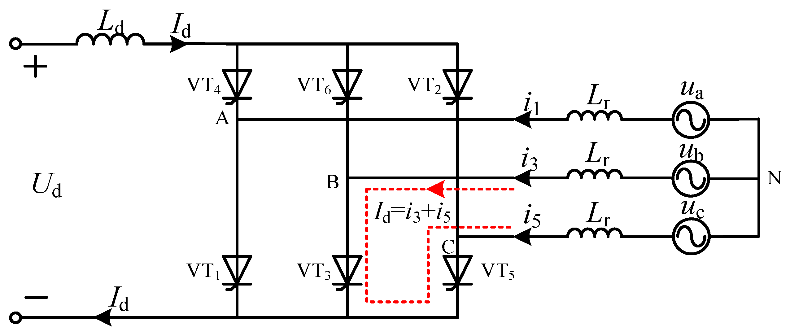
2.2.1. Analysis of the Effect Exerted by AC Voltage Decline on DC Current

In this section, we qualitatively analyze the impact of the voltage drop on the current through the connection between the AC system on the inverter side and the DC line. Figure 4 illustrates an equivalent circuit diagram for the HVDC system [32].
When a grounding fault is reported on the inverter side, the AC voltage will decrease. To more intuitively analyze the effects of the drop in AC voltage on the DC current, the inhibition effect of the energy storage component of the direct-current transmission system on the DC current is ignored. The expression of the DC current can be obtained from Figure 4 as follows:
I d = ( U dr U d i ) / R d U dr = U dor cos α I d d r U di = U doi cos γ I d d i
where Udoi = (3 2 /π) NULI, dr = 3NXcr/π, and di = 3NXci/π. The functional relationship between the DC current and the bus voltage of the AC is represented in Equation (8):
I d = U dor cos α 3 2 π N U Li cos γ R d + 3 N ( X cr X ci ) π
The partial derivative of Id with respect to ULI can be obtained from Equation (8):
I d U Li = 3 2 N cos γ π R d + 3 N ( X cr X ci )
Equation (9) is constantly negative, and the DC current is elevated as the AC bus voltage drops when the inverter-side AC system fails.

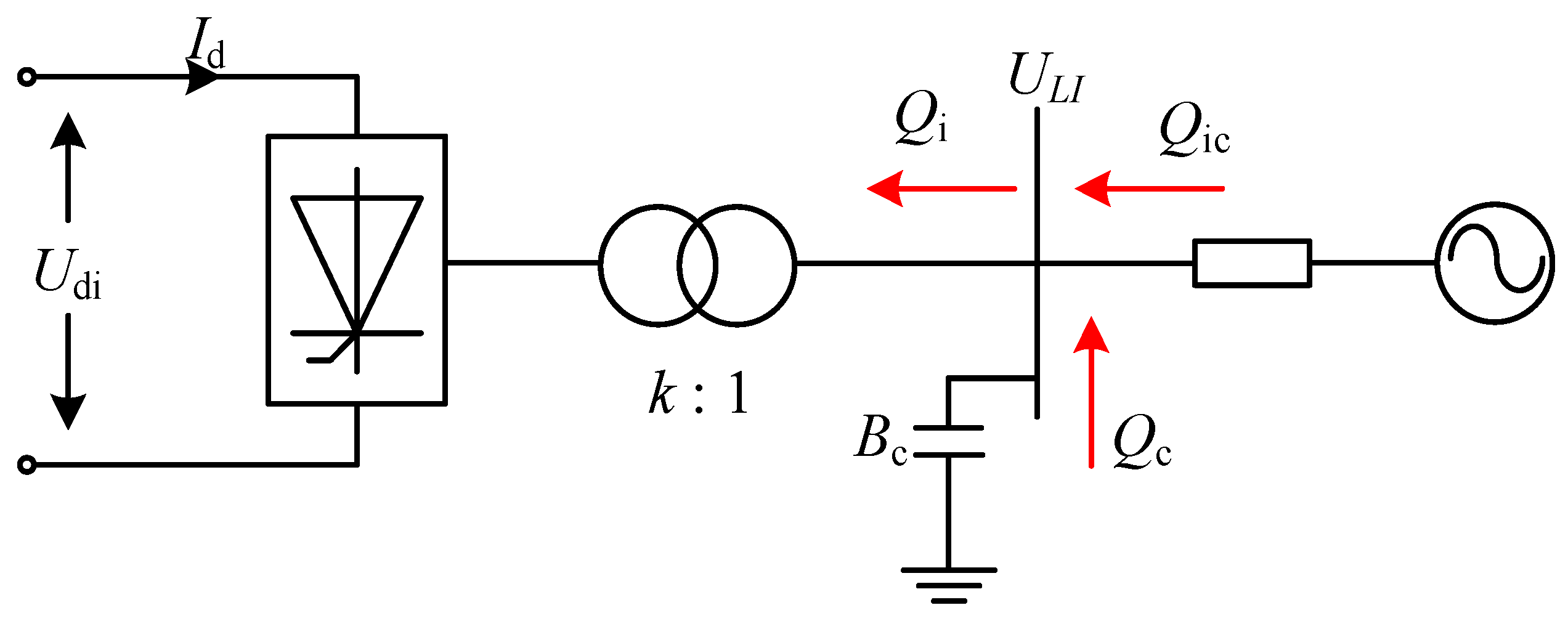
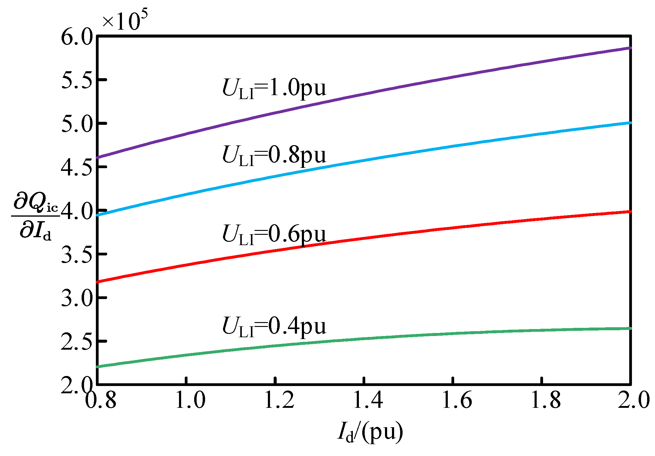
2.2.2. Analysis of the Effect of DC Current Elevation on AC Voltage

Figure 5 presents an exchange situation of reactive power [33] between the inverter station and alternating current system of the HVDC transmission system. In this section, a qualitative analysis is carried out from the perspective of the effects of reactive power variation on voltage.
In stable operation, the alternating current filter’s reactive power supply on the inverter side is capable of confirming the inverter station’s reactive power consumption, and the inverter station does not need to obtain reactive power from the alternating current receiver system. The increase in the DC current exert effect on the AC voltage through the reactive power exchange between the alternating current receiver system and the inverter station is illustrated in the diagram above. As shown in Figure 5, the reactive power balance equation at the alternating current busbar of the inverter station can be written as follows:
Q ic = Q i Q c Q i = I d U doi 2 U di 2 Q c = B c U Li 2
In Equation (10), the reactive power exchange capacity between the 12-pulse inverter and the alternating current system can be expressed as
Q i c = I d 72 π 2 U Li 2 6 2 π U Li cos γ 6 X c I d π 2 2 B c U Li
The partial derivative of Qic regarding Id is expressed based on Equation (11) as
Q ic I d = 72 π 2 U Li 2 6 X c I d π 6 2 π U Li cos γ 2 6 X c I d π 6 X c I d π 6 2 π U Li cos γ 72 π 2 U Li 2 6 X c I d π 6 2 π U Li cos γ 2
The partial derivative of reactive power exchange capacity with respect to the DC current under different AC voltages is obtained by bringing in data, as shown in Figure 6.
As shown in Figure 6, the partial derivatives are positive at different AC voltages, indicating that the capacity of the reactive power exchanged between the inverter station and the alternating current system is positively correlated with the DC current. When a fault is identified, the reactive power balance is broken with the elevation of the DC current, and the inverter station absorbs more reactive power from the alternating current system on the inverter side to maintain the power balance. On this basis, the AC voltage decreases further.
As revealed by the above analysis, the current of DC and the AC voltage are the main factors affecting the turn-off angle, and there is a coupling relationship between them. If only a single factor is considered for commutation failure analysis, a significant error will be generated, such that a more accurate commutation failure criterion can be developed in accordance with the coupling relationship between the current of DC and AC voltage.

3. Analysis of Asymmetric Fault Commutation Failure Considering Transient Increases in DC Current

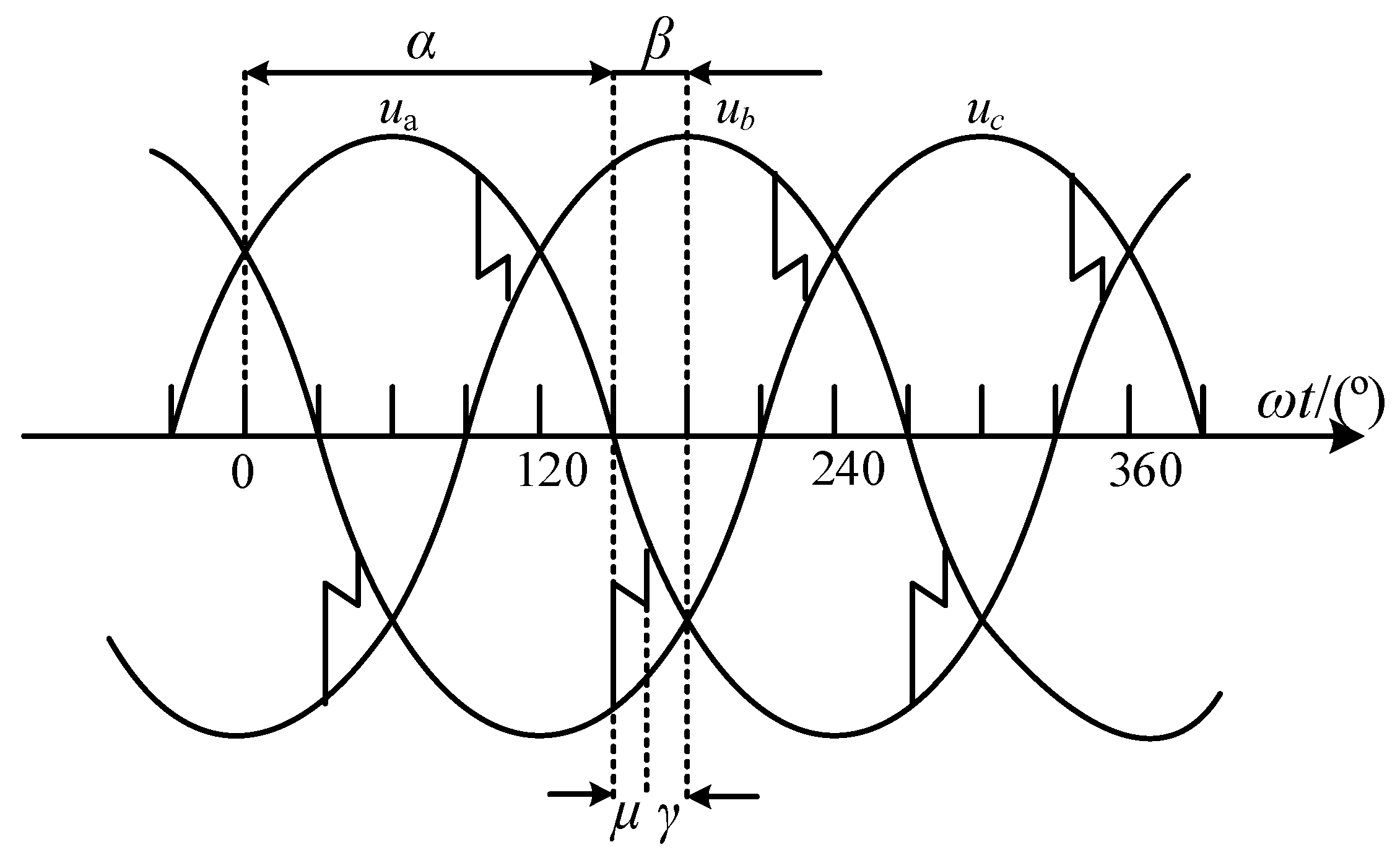
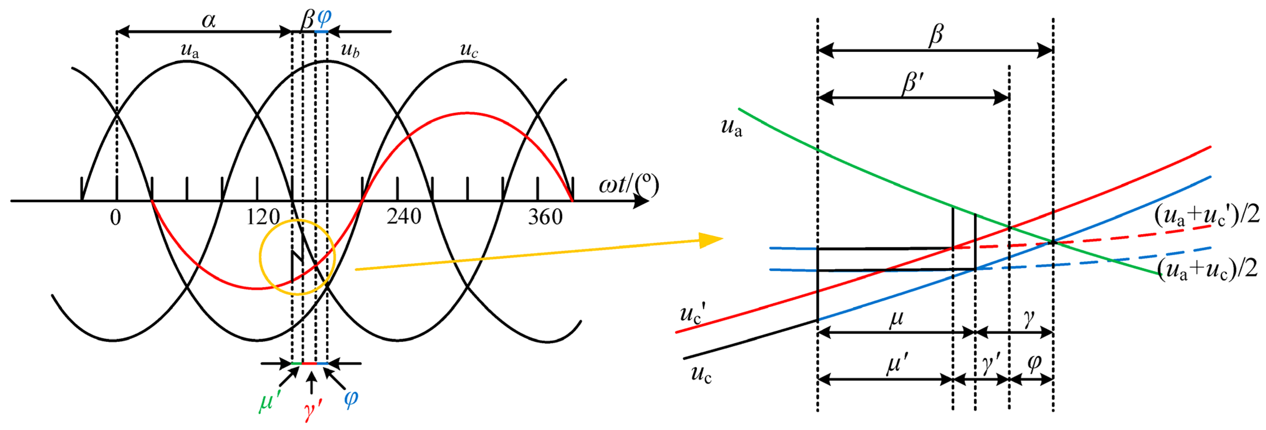
3.1. Qualitative Analysis of the Effect of Asymmetric Faults on Commutation Failures

In the power system, compared with three-phase short-circuit faults, single-phase short-circuit faults occur more frequently. Therefore, exploring the effect of single-phase short-circuit grounding faults on commutation failure has high practice significance in engineering. In the following, the effect of single-phase short-circuit grounding faults on the turn-off angle will be qualitatively analyzed. The following figure (Figure 7) shows the voltage waveform diagram of the inverter during normal operation.
At this stage, the system is in a stable state, and the turn-off angle is greater than the critical one, enabling the system to meet the requirements for extinguishing the thyristor. When a three-phase symmetrical fault occurs in the system, the variation characteristics of each phase voltage are consistent, so the zero-crossing point of the commutation voltage is not offset. However, for single-phase asymmetric faults, the variation characteristics of three-phase voltages are not exactly the same after the fault occurs, and the zero-crossing of commutation voltages will be offset. Taking the phase C grounding fault as an example, the commutation voltage offset characteristics under a single-phase grounding fault are analyzed. When a single-phase grounding fault occurs in phase C of the system, the voltage of phase C decreases from uc to uc′. The inverter side voltage waveform and its local amplification diagram at this stage are shown in the following figure (Figure 8).
As the C-phase voltage decreases, the original phase angle balance between the three phase voltages will be broken, and the C-phase voltage will be shifted forward by an angle of φ [34] before the zero-crossing point. The production of φ will compress the size of γ, thus reducing γ to γ′, which has a negative impact on the regular commutation of the system.

3.2. HVDC System Modeling and the Calculation Method for the Critical Voltage Instantaneous Value Criterion

The above section qualitatively analyzed the mechanism by which the voltage-over-zero offset angle generated by a single-phase grounding fault affects commutation failure. However, in order to accurately obtain the critical voltage instantaneous value leading to commutation failure, further quantitative analyses of the voltage reduction and phase shift generated by a single-phase fault in the inverter-side AC system, and their relationships with the DC system, are required.
The Laplace circuit of the DC line is shown in Figure 9.
Energy storage components such as large-capacity smoothing reactors and line capacitors in DC lines will hinder the DC current. However, as shown in Figure 10, the current generated by the line capacitance is one order of magnitude smaller than the fault current, so the effect of its action is ignored.
According to Kirchhoff’s voltage law (KVL), Equation (13) can be obtained as follows:
U dor cos α s + L I d ( 0 ) I d ( d r + R d 2 + s L ) = U doi cos γ s L I d ( 0 ) + I d ( R d 2 d i + s L )
Introducing the initial current of the energy storage element Id (0−) = Idn into Equation (13) for an inverse Laplace transformation yields the time domain expression for the DC line:
I d ( t ) = U dor cos α 3 2 π N U Li cos γ R d + d r d i 1 A + A I dn A = e R d + d r d i 2 L · t
When the alternating current system on the inverter side fails asymmetrically (assuming that a grounding fault occurs in phase A), the A-phase voltage decreases by ΔUA, while the voltages of phase B and C remain unchanged. A voltage vector diagram of the corresponding converter bus is shown below.
As depicted in Figure 11, the forward angle of commutation voltage φ is expressed as
φ = arctan Δ U A 2 3 3 Δ U A
Using Figure 11, in accordance with the cosine theorem, yields the following:
| U AC | = | U AB | = | U A | 2 + | U B | 2 + 2 | U A | | U B | cos 120 o
When a fault is identified in phase A, the following equation can be used:
| U A | = | Δ U A | + | U A |
In accordance with Equations (16) and (17), the correlation between the line voltage and A-phase voltage drop after an A-phase fault is reported can be obtained as
U AC = U AB = 3 U A 2 3 Δ U A U A + Δ U A 2
Equation (18) can then be converted into the per-unit value as
U Li = U AC = U AB = 1 Δ U A + Δ U A 2 3
By substituting Equations (14), (15) and (19) into Equation (6), a single relation expression between the turn-off angle of asymmetric faults and the AC voltage is obtained:
γ = arccos B U Li + cos β a 2 + b 2 + arctan a b
In Equation (20),
B = 2 X c I dn A + U dor cos α R d + d r d i ( 1 A ) U LiN a 2 + b 2 a = sin φ ; b = cos φ + 2 X c 3 2 N ( 1 A ) π ( R d + d r d i )
When asymmetric faults occur on the inverter side, the maximum transient time for the first commutation failure is nearly 5.5 ms [35]. Thus, to obtain a more conservative criterion for the instantaneous value of commutation failure voltage, t = 5.5 ms is selected as the time when commutation failure is identified. By substituting the critical turn-off angle γmin into Equation (20), the critical instantaneous value of the AC voltage ULImin at which commutation failure is reported can be obtained.

4. Simulation Results and Discussions

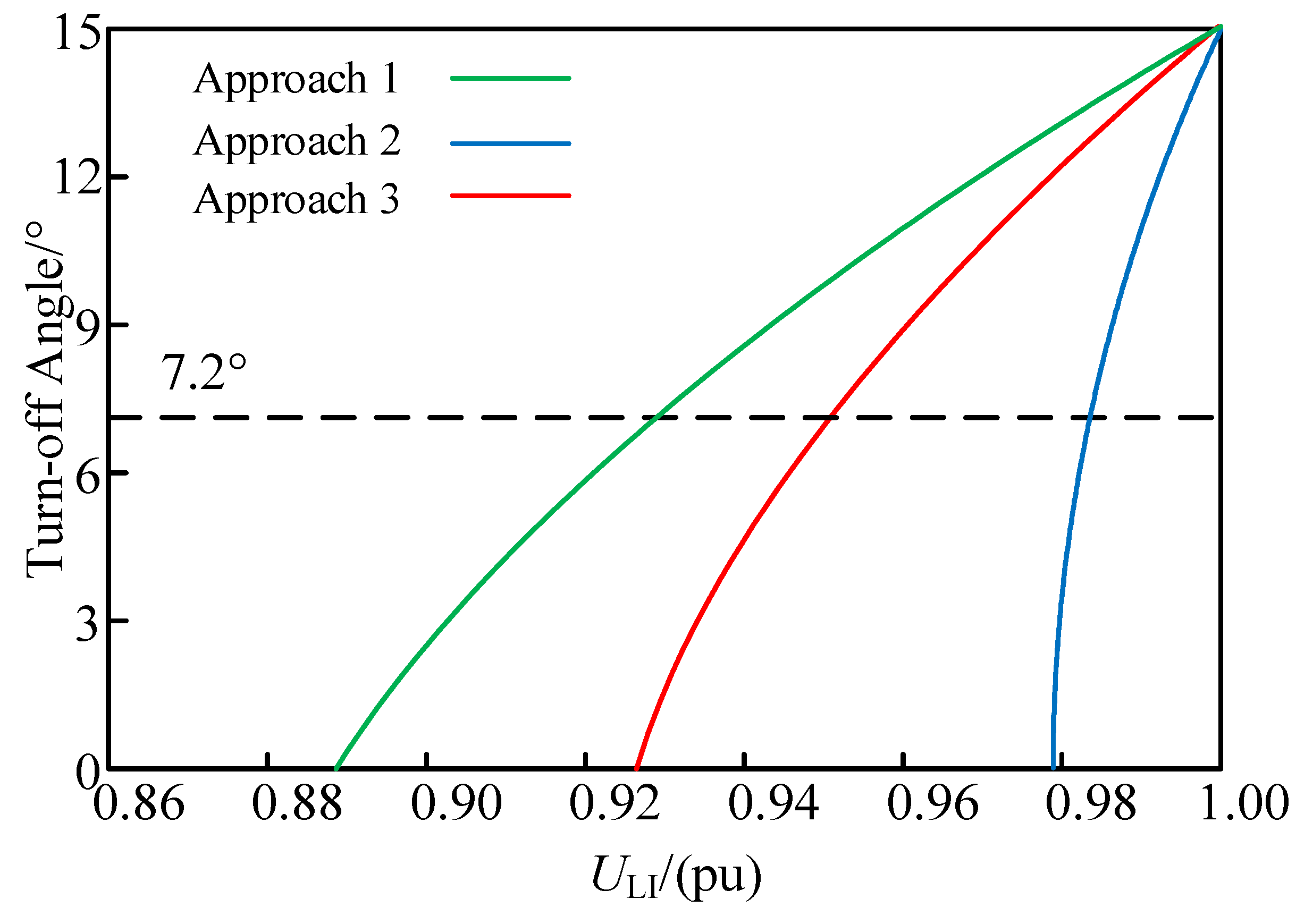
4.1. Simulation Validation

The simulation is based on the CIGRE HVDC model built in the PSCAD transient simulation software, and the parameters are shown in Table A1, Appendix A. The correlation between the turn-off angle and voltage based on three commutation failure analysis approaches under asymmetric faults is shown in Figure 12.
Approach 1: The effect of the elevation of the DC current on the turn-off angle during a fault is not considered.
Approach 2: Decoupling is achieved by ignoring the DC line energy storage elements in [22].
Approach 3: Decoupling of considering smoothing reactors in the DC lines is performed as described in this study.
As depicted in Figure 12, when a single-phase grounding fault is identified in the AC system, the critical commutation failure voltages of the three analysis approaches are 0.929 pu, 0.984 pu, and 0.953 pu, respectively.
A single-phase grounding fault occurs at the AC bus on the inverter side with a short-circuit impedance of 163 Ω is set at 1 s, such that a commutation failure is reported, i.e., the turn-off angle decreases to 7.2°, and the failure lasts for 0.05 s. Figure 13 presents the response characteristics after failure.
Figure 13 shows a diagram for when the system fails in commutation, i.e., when the turn-off angle drops to 7.2°, and the AC bus voltage is 0.954 pu.
If approach 1 is adopted, and the AC voltage decreases to 0.929 pu, it is judged that commutation failure is reported in the system. This approach does not consider the effect of increased DC current on the turn-off angle after AC system failure. Moreover, the calculation results are optimistic, which will lead the slow speed of the system to issue commutation failure instructions, which are not conducive to the implementation of subsequent protection measures.
If approach 2 is used, the discrimination result of commutation failure is given when the AC voltage decreases to 0.984 pu, which is contrary to the simulation results. This approach ignores the inhibition effects of the energy storage element on the DC current in the DC line. Accordingly, approach 2 exaggerates the effects of the DC current on the turn-off angle to a certain extent, making the discrimination results more conservative and causing the system to misjudge.
However, approach 3 developed in this study considers the role of the smoothing reactors in obstructing the current. Here, commutation failure is identified when the AC voltage drops to 0.953 pu, which is basically consistent with the simulation results and is more applicable to the analysis of commutation failure. Small errors occur because the approach developed in this study does not consider the effects of the line capacitance and harmonics generated after an alternating current system fault.
To further verify the accuracy of the developed approach, the CIGRE HVDC model is used to set the single-phase grounding faults with different severity levels. The results are shown in Table 1.
Table 1 shows that the developed commutation failure analysis approach considering the smoothing reactors is more accurate than the other two approaches.
To further reflect the accuracy of the analysis approach proposed in this paper compared with the other two methods, we define the percentage of error formula as follows:
E R = S V C V S V × 100 %
The error situation of the three approaches for different minimum turn-off angles is shown in Table 2.
According to the above table, the proposed method produces smaller errors than other methods and makes the judgment of commutation failure more accurate.

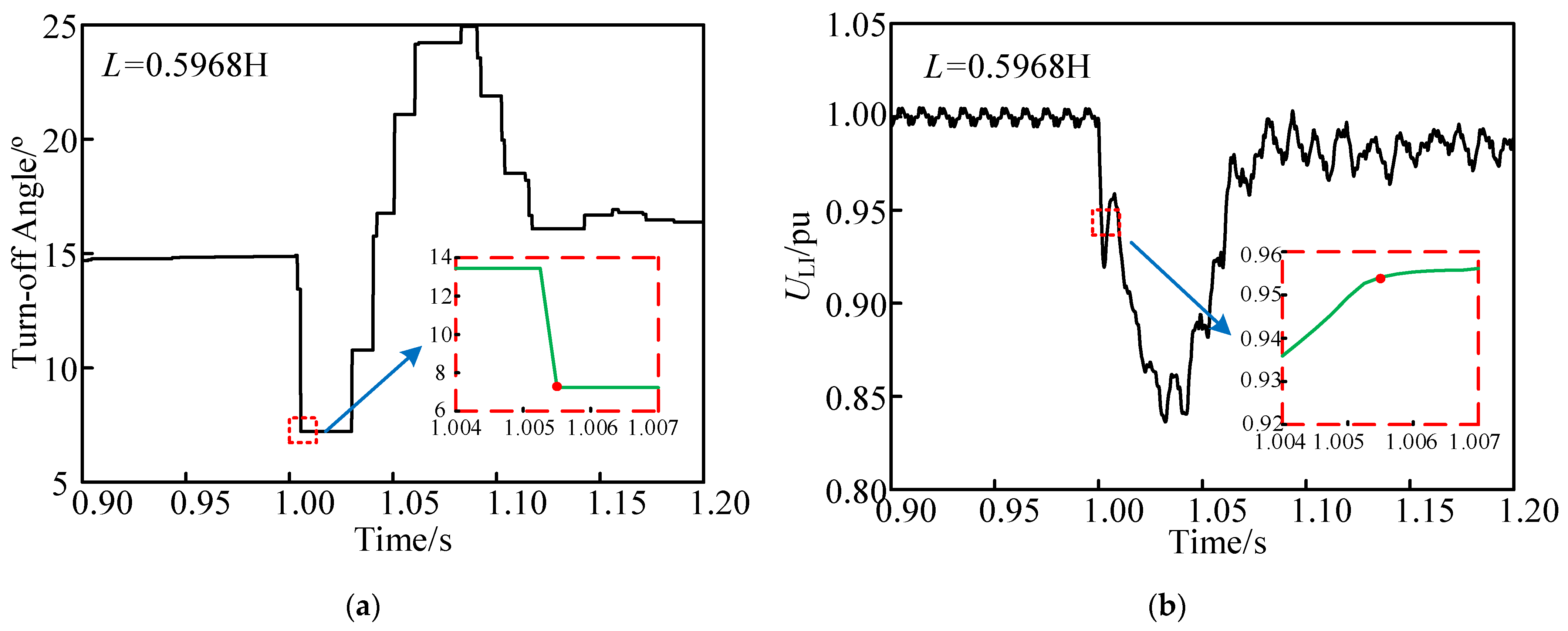
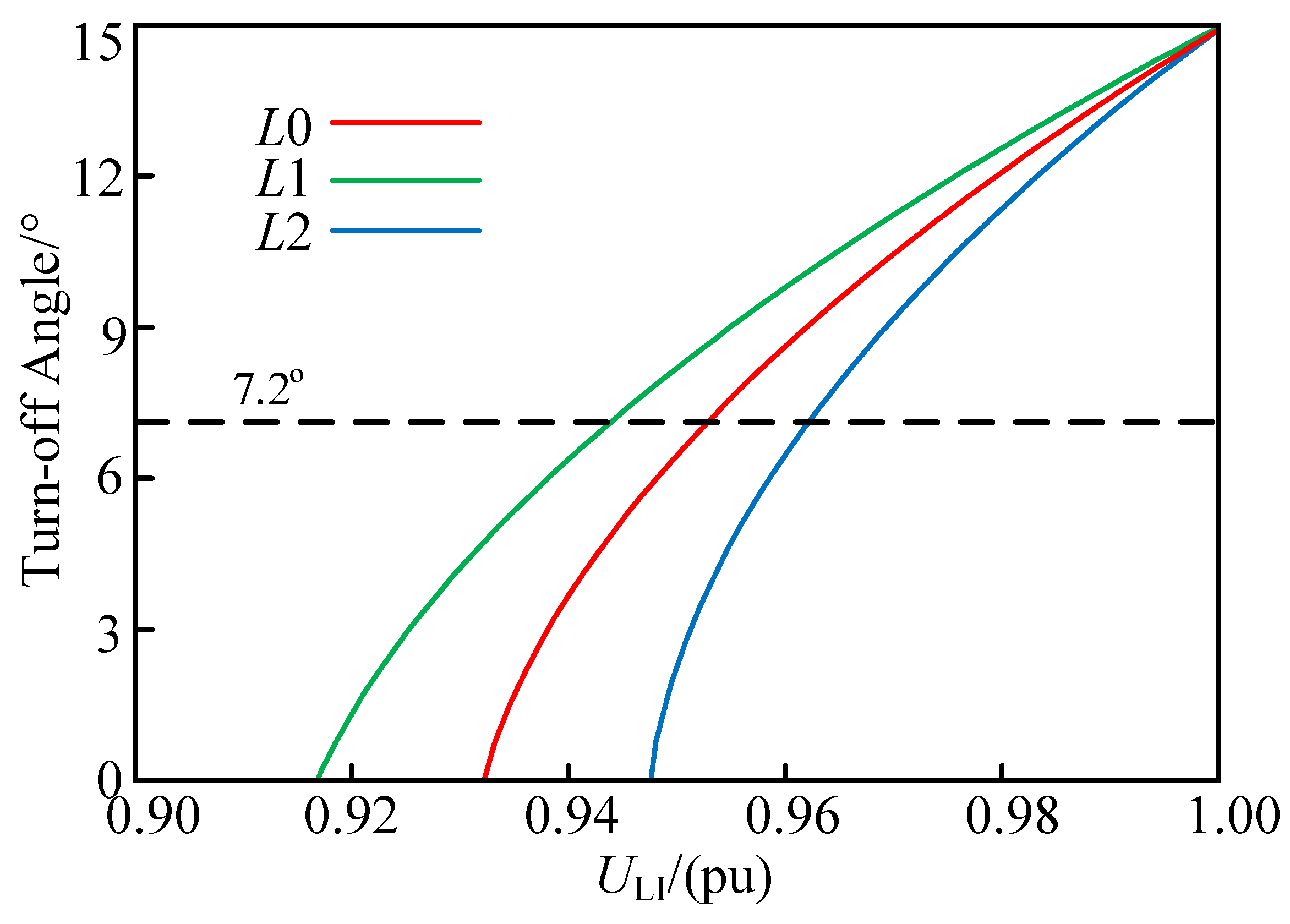
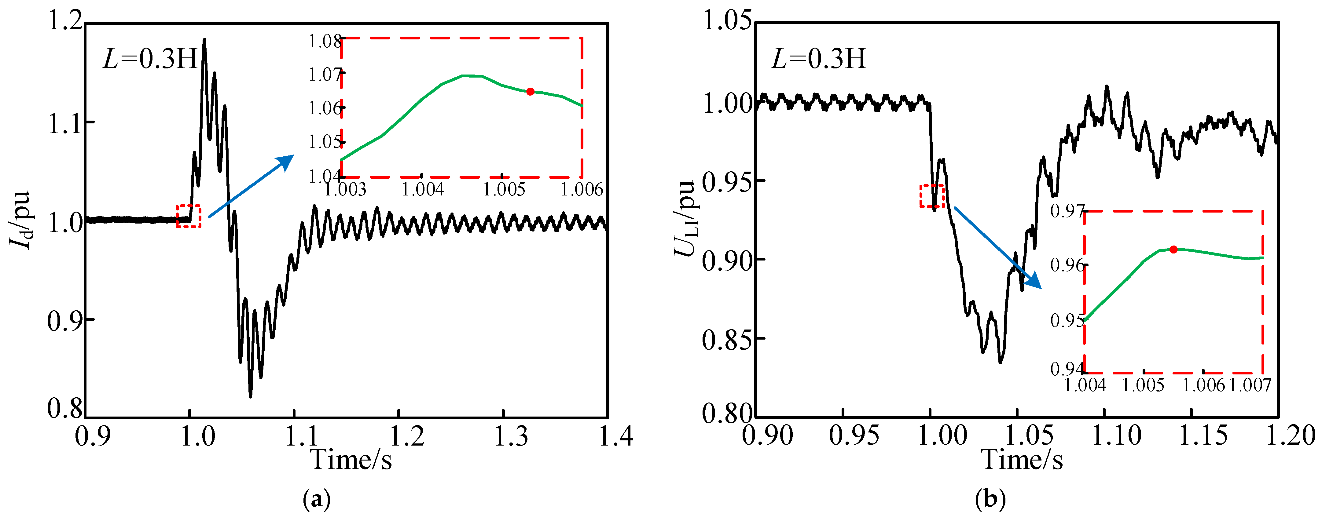
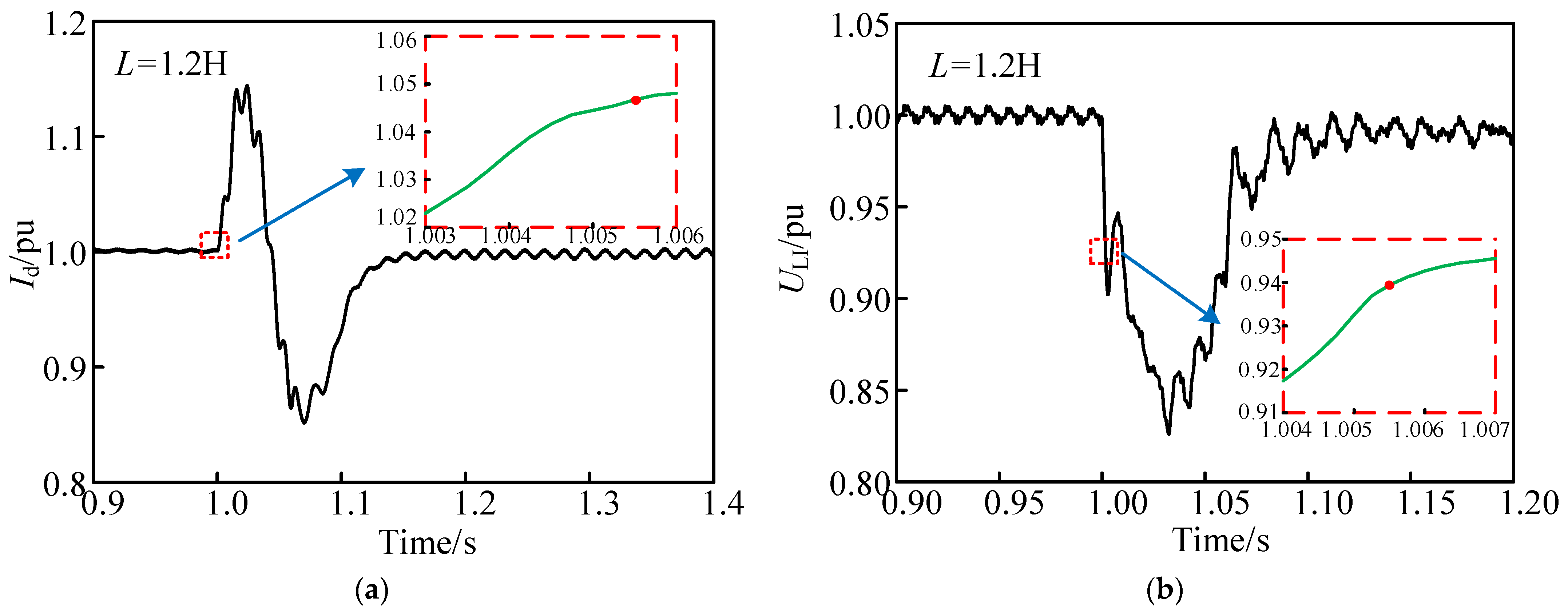
4.2. Analysis of the Effect of the Smoothing Reactors on Commutation Failure

Approaches 1 and 2 do not consider the effects of smoothing reactors on the DC current, such that the critical voltage of commutation failure is constant for smoothing reactors with different sizes of the same DC line. This situation is clearly not consistent with reality, and the developed approach is capable of accurately predicting the critical voltage of commutation failure when smoothing reactors with different parameters are adopted. In the CIGRE HVDC model, the smoothing reactor’s parameters are 1/2 and 2 times the original parameter values, i.e., L1 = 0.3 H and L2 = 1.2 H, to verify the accuracy of the developed approach.
Figure 14 presents the correlation between the turn-off angle and AC voltage based on the three parameters in the presence of a single-phase grounding fault in the system.
As depicted in Figure 14, when the original parameter is employed, commutation failure can be identified with a decrease in the AC voltage to 0.954 pu. When parameters 1 and 2 are adopted, commutation failure occurs when the AC voltage decreases to 0.944 pu and 0.963 pu, respectively.
The following figures (Figure 15, Figure 16 and Figure 17) respectively presents the simulation results for the current of DC and AC voltage when three parameters are adopted. Additionally, different short-circuit impedance values are set at the AC bus on the inverter side, such that the system exactly fails to change phase.
When a single-phase grounding fault with short-circuit impedance of 163 Ω is set in the system with the original parameters, and the turn-off angle decreases to 7.2°, the DC current is elevated to 1.058 pu, and the AC voltage decreases to 0.954 pu.
When a single-phase grounding fault with short-circuit impedance of 178 Ω is set in the system with the original parameters, and the turn-off angle decreases to 7.2°, the DC current is elevated to 1.064 pu, and the AC voltage falls to 0.963 pu. In general, the simulation results of this parameter are consistent with the calculated results for 0.961 pu. When parameter 1 is adopted, the DC current is slightly higher than that of the original parameter. The reason for the above result is that the suppression effect of the smoothing reactor using parameter 1 on the DC current is weakened compared with the original parameter, and the increase rate of the DC current is accelerated. Furthermore, the system’s resistance to commutation failure is weakened, as revealed by the short-circuit impedance, which makes the system fail during commutation.
When a single-phase grounding fault with short-circuit impedance of 140 Ω is set in the system with the original parameters, and the turn-off angle decreases to 7.2°, the DC current is elevated to 1.046 pu, and the AC voltage decreases to 0.941 pu. In general, the simulation results of this parameter are consistent with the calculated results for 0.944 pu. The DC current is slightly reduced when using parameter 2 compared with using the original parameter. The reason for the above result is that the anti-mutation ability of the smoothing reactor using parameter 2 on the DC current is enhanced compared with the original parameter, and the increase rate of the DC current is reduced. Furthermore, the system’s resistance to commutation failure is increased, as revealed by the short-circuit impedance, which makes the system fail during commutation.
The above analysis suggests that the system’s resistance to commutation failure is significantly correlated with the smoothing reactors, such that the commutation failure analysis approach adopted in Approach 1, 2 leads to a significant error. An analysis approach of commutation failure for counting smoothing reactors was developed in this study. Through a simulation experiment on smoothing reactors with different parameters, the instantaneous value of the AC voltage was found to be consistent with the calculated results when the commutation failed, further verifying the accuracy of the developed approach.

5. Conclusions

This study proposed a commutation failure analysis approach considering the instantaneous values of the current of DC and the AC voltage after asymmetric faults in HVDC transmission systems and verified the accuracy of this approach compared with the other two approaches through simulation experiments.
In this study, the effects of the current of DC and the AC voltage on commutation failure was analyzed using the mechanism with the voltage time integral area approach at first. Additionally, the coupling relationship between the current of DC and the AC voltage was analyzed in accordance with the connection between the inverter station and the alternating current system.
The DC line equivalent circuit model that covers the reactor was built in Laplace space, the DC current and the AC voltage were decoupled, and the transient time domain expressions capable of characterizing the instantaneous variations in AC voltage and DC current after asymmetrical faults of the system were outlined. The critical voltage instantaneous value leading to commutation failure of the system was determined by integrating the zero-crossing offset angle with the critical turn-off angle of the voltage after an asymmetric fault of the system. The above-described criterion was capable of increasing the accuracy of the estimation of commutation failure under asymmetric faults and compensating for the deficiencies of existing commutation failure analysis approaches that do not consider instantaneous variation of the DC current.
In the simulation of different reactor parameters, the line parameter pair showed a significant correlation with the system’s immunity ability to commutation failure. With elevated reactor parameters, the ability to suppress mutation of the DC current after the fault will be enhanced, and a commutation failure will be less likely to occur. This result further verifies the applicability of the developed approach to different systems. The decoupling approach for the current of DC and the AC voltage developed in this study provides novel insights for the prevention and suppression of commutation failures and holds great significance in theoretically guiding the planning and operation of HVDC systems.

Author Contributions

Y.W.: conceptualization, methodology, and original writing. H.W.: conceptualization, methodology, and supervision. J.W.: formal analysis and validation. All authors have read and agreed to the published version of the manuscript.

Funding

This research was funded by the National Key Research and Development Program of China, grant number 2021YFB1507005.

Institutional Review Board Statement

Not applicable.

Informed Consent Statement

Not applicable.

Data Availability Statement

The data can be provided upon the request to the authors.

Conflicts of Interest

The authors declare no conflict of interest.

Appendix A

Table A1. Nomenclature and numerical values.
SymbolsParameter NameParameter Size
drCommutation resistance on the rectifier side25.9446
diCommutation resistance on the inverter side25.4309
XCREquivalent commutation reactance on the rectifier side13.5842 Ω
XCIEquivalent inverter commutation on the reactance side13.3152 Ω
UdorRated no-load voltage at the valve side of the converter transformer on the rectifier side589.1 KV
CLine capacitance0.01184 S
LLine inductance0.5968 H
IdDC current2 KA
ULiAC voltage205.5 KV
NNumber of converters2
γTurn-off angle15°
γminCritical turn-off angle7.2°
αDelayed trigger angle20°
βAdvance trigger angle38°
QiReactive power consumption of the inverter station
QcReactive power supply of the AC filter
QicThe amount of reactive power exchanged between the inverter station and AC system
UdrVoltage of DC on the inverter side
UdiVoltage of DC on the rectifier side
ERPercentage of error
SVSimulation value
CVCalculated value

References

  1. Zhu, Y.; Huang, L.; Li, S.; Zhu, Y.; Jia, X.; Song, Y. Research and Implementation of Control Strategies for Multiple Transmission Modes in Yongren-Funing HVDC. In Proceedings of the 2022 IEEE International Conference on Power Systems and Electrical Technology, Aalborg, Denmark, 13–15 October 2022; pp. 36–40. [Google Scholar]
  2. Song, J.Z.; Li, Y.L.; Zeng, L.; Zhang, Y. Review on commutation failure of HVDC transmission system. Autom. Electr. Power Syst. 2020, 44, 2–13. [Google Scholar]
  3. Zhu, R.; Zhou, X.; Yin, H.; Liu, Y.; Deng, L.; Hong, L. Commutation Failure Analysis Considering the Frequency Response of Transmission Line. In Proceedings of the 2021 IEEE 2nd China International Youth Conference on Electrical Engineering, Chengdu, China, 15–17 December 2021; pp. 1–6. [Google Scholar]
  4. Song, J.; Li, Y.; Zeng, L.; Zhang, Y.; Yang, Z. Mechanism Analysis and Prevention Methods of Commutation Failure in LCC-HVDC Transmission System. In Proceedings of the 2019 IEEE 8th International Conference on Advanced Power System Automation and Protection, Xi’an, China, 21–24 October 2019; pp. 556–560. [Google Scholar]
  5. Zheng, B.; Hu, J.; Wang, T.; Wang, Z. Mechanism Analysis of a Subsequent Commutation Failure and a DC Power Recovery Speed Control Strategy. Electronics 2022, 11, 998. [Google Scholar] [CrossRef]
  6. Tian, D.; Xiong, X.; Xiao, C. Early Warning and Inhibition of HVDC Subsequent Commutation Failure During Recovery Process Under Grid Fault. IEEE Trans. Power Deliv. 2021, 36, 1051–1062. [Google Scholar] [CrossRef]
  7. Zhang, Y.; Tang, F.; Qin, F.; Li, Y.; Gao, X.; Du, N. Research on Dynamic Reactive Power Compensation Scheme for Inhibiting Subsequent Commutation Failure of MIDC. Sustainability 2021, 13, 7829. [Google Scholar] [CrossRef]
  8. Zhou, X.; Ding, C.; Dai, J.; Li, Z.; Hu, Y.; Qie, Z.; Xue, F. An Active Power Coordination Control Strategy for AC/DC Transmission Systems to Mitigate Subsequent Commutation Failures in HVDC Systems. Electronics 2021, 10, 3044. [Google Scholar] [CrossRef]
  9. Jiang, J.; Lan, Z.; Pan, M.; Sun, K.; Wang, J. Analysis of commutation failure propagation characteristics and influence factor of multi-infeed LCC-HVDC system. In Proceedings of the 2021 IEEE 4th International Electrical and Energy Conference, Wuhan, China, 28–30 May 2021; pp. 1–6. [Google Scholar]
  10. Wang, Z.; Liu, X.; Zheng, B.; Li, Y. The research on fast prediction and suppression measures of commutation failure based on voltage waveform fitting. Trans. China Electrotech. Soc. 2020, 35, 1454–1463. [Google Scholar]
  11. Thio, C.V.; Davies, J.B.; Kent, K.L. Commutation failures in HVDC transmission systems. IEEE Trans. Power Deliv. 1996, 11, 946–957. [Google Scholar] [CrossRef]
  12. Tong, W.; Chen, M.; Yang, G.; Wang, J.; Xiao, T. Optimization of Series Reactors and VAR Compensators Installation for Inhibiting Multiinfeed HVDC Commutation Failure. In Proceedings of the 2020 IEEE 1st China International Youth Conference on Electrical Engineering, Wuhan, China, 1–4 November 2020; pp. 1–7. [Google Scholar]
  13. Yang, W.; Cai, Z.; Li, X.; Yu, C. Assessment of commutation failure in HVDC systems considering spatial-temporal discreteness of AC system faults. J. Mod. Power Syst. Clean Energy 2018, 6, 1055–1065. [Google Scholar] [CrossRef] [Green Version]
  14. Zhou, B.; Li, F.; Yin, C. Risk evaluation and suppression methods for subsequent commutation failure of HVDC transmission system. Autom. Electr. Power Syst. 2021, 45, 143–151. [Google Scholar]
  15. Xu, H.; Yang, W.; Zhang, D.; Miao, S.; Wang, Y. Commutation failure judgment method for multi-Infeed HVDC systems considering the interaction of commutation failures. Trans. China Electrotech. Soc. 2020, 35, 1776–1786. [Google Scholar]
  16. Guo, Y.; Tan, Z.; Li, X.; Wang, Y.; Liu, Z.; Cai, Z.; Chen, Z. A Hierarchical Identification Method of Commutation Failure Risk Areas in Multi-Infeed LCC-HVDC Systems. IEEE Trans. Power Syst. 2023, 10, 1–12. [Google Scholar] [CrossRef]
  17. Li, M.; Zhang, W.; Hu, B.; Kang, J.; Wang, Y.; Lu, S. Automatic Assessment of Depression and Anxiety through Encoding Pupil-wave from HCI in VR Scenes. ACM Trans. Multimed. Comput. Commun. Appl. 2022. [Google Scholar] [CrossRef]
  18. Zhou, X.; Cai, X.; Zhang, H.; Zhang, Z.; Jin, T.; Chen, H.; Deng, W. Multi-strategy competitive-cooperative co-evolutionary algorithm and its application. Inf. Sci. 2023, 635, 328–344. [Google Scholar] [CrossRef]
  19. Huang, C.; Zhou, X.; Ran, X.; Wang, J.; Chen, H.; Deng, W. Adaptive cylinder vector particle swarm optimization with differential evolution for UAV path planning. Eng. Appl. Artif. Intell. 2023, 121, 105942. [Google Scholar] [CrossRef]
  20. Yu, Y.; Tang, K.; Liu, Y. A Fine-Tuning Based Approach for Daily Activity Recognition between Smart Homes. Appl. Sci. 2023, 13, 5706. [Google Scholar] [CrossRef]
  21. Dong, X.; Tang, Y.; Bu, G. Confronting problem and challenge of large scale AC-DC hybrid power grid operation. Proc. CSEE 2019, 39, 3107–3119. [Google Scholar]
  22. Xu, J.; Tan, H.; Sun, H.; Wu, J. Research on method to analyze commutation failure in HVDC power transmission system considering the impact of DC current variation and occurrence moment of AC fault. Power Syst. Technol. 2015, 39, 1261–1267. [Google Scholar]
  23. Ouyang, J.; Zhang, Z.; Xiao, C. Improved Prevention and Control Strategy of Commutation Failure in HVDC Transmission System. Autom. Electr. Power Syst. 2020, 44, 14–21. [Google Scholar]
  24. Ouyang, J.; Zhang, Z.; Li, M.; Pang, M.; Xiong, X.; Diao, Y. A Predictive Method of LCC-HVDC Continuous Commutation Failure Based on Threshold Commutation Voltage Under Grid Fault. IEEE Trans. Power Syst. 2021, 36, 118–126. [Google Scholar] [CrossRef]
  25. W, F.; Liu, T.; Li, X.; Yang, J. Commutation failure analysis considering DC current rise and AC voltage drop speed. Autom. Electr. Power Syst. 2016, 40, 111–117. [Google Scholar]
  26. Wang, L.; Li, F.; Yin, C.; Xin, C. Analysis of asymmetric fault commutation failure in an HVDC system with DC current variation. Power Syst. Prot. Control 2021, 49, 17–23. [Google Scholar]
  27. Wang, T.; Jia, K.; Bi, T.; Zhao, Q.; Feng, T.; Li, W. Transient characteristics of commutation failure of HVDC system based on dynamic phasor theory. Autom. Electr. Power Syst. 2018, 42, 78–85. [Google Scholar]
  28. Zhou, B.; Li, F.; Yin, C.; Zhang, Z. Preventive strategy for mitigation of commutation failure based on finite time domain prediction algorithm of DC current. Autom. Electr. Power Syst. 2020, 44, 178–185. [Google Scholar]
  29. Wang, F.; Liu, T.; You, X.; Su, G.; Liu, Y.; Liu, H. Critical instantaneous voltage of commutation failure based on transient DC current prediction. High Volt. Eng. 2021, 47, 129–137. [Google Scholar]
  30. Wang, Y.; Wu, L.; Chen, S. A Simplified Model of the HVDC Transmission System for Sub-Synchronous Oscillations. Sustainability 2023, 15, 7444. [Google Scholar] [CrossRef]
  31. Yu, D.; Gao, S.; Zhao, X.; Liu, Y.; Wang, S.; Song, T.E. Alternating Iterative Power-Flow Algorithm for Hybrid AC–DC Power Grids Incorporating LCCs and VSCs. Sustainability 2023, 15, 4573. [Google Scholar] [CrossRef]
  32. Li, R.; Li, Y.; Chen, X. A Control Method for Suppressing the Continuous Commutation Failure of HVDC Transmission. Proc. CSEE 2018, 38, 5029–5042. [Google Scholar]
  33. Wang, J.; Zheng, R.; Fu, C.; Wu, Q. A Method Based on Constant Reactive Power Control of Inverter to Suppress the Subsequent Commutation Failure in HVDC System. Trans. China Electrotech. Soc. 2023, 7, 1544–1554. [Google Scholar]
  34. Zhao, J.; Li, X.; Zhang, J.; Chen, Z. Assessment of commutation failure under asymmetric fault in the HVDC inverter side. In Proceedings of the 2021 Annual Meeting of CSEE Study Committee of HVDC and Power Electronics, Hybrid Conference, China, 28–30 December 2021; pp. 51–56. [Google Scholar]
  35. Guo, C.; Zhao, J.; Liu, W. A review of methods to mitigate the commutation failure for LCC-HVDC. Proc. CSEE 2018, 38, 1–10. [Google Scholar]
Figure 1. The structure of the three-phase six pulse inverter.
Sustainability 15 11796 g001
Figure 2. The time-integral area schematic diagram of commutation voltage in two cases: (a) AC voltage drop; (b) DC current increase.
Sustainability 15 11796 g002
Figure 3. The response characteristics of the AC voltage and the DC current with respect to the turn-off angle: (a) when the DC current is increased; (b) when the AC voltage is decreased.
Sustainability 15 11796 g003
Figure 4. The HVDC system equivalent circuit.
Sustainability 15 11796 g004
Figure 5. Schematic diagram of reactive power exchange between the inverter station and AC system.
Sustainability 15 11796 g005
Figure 6. Partial derivative of Qic with respect to Id under different AC voltages.
Sustainability 15 11796 g006
Figure 7. Waveform of inverter voltage (normal operation).
Sustainability 15 11796 g007
Figure 8. Waveform of inverter voltage (fault in phase C).
Sustainability 15 11796 g008
Figure 9. Laplace transformation circuit diagram of the DC line.
Sustainability 15 11796 g009
Figure 10. Schematic diagram of the line fault current and capacitor fault current.
Sustainability 15 11796 g010
Figure 11. Voltage vector diagram of the AC converter bus.
Sustainability 15 11796 g011
Figure 12. Response diagram of the AC voltage and turn-off angle under different approaches.
Sustainability 15 11796 g012
Figure 13. System-response characteristic diagram for when a commutation failure occurs: (a) turn-off angle response characteristic diagram; (b) AC voltage response characteristic diagram.
Sustainability 15 11796 g013
Figure 14. Diagram of the correlation between the AC voltage and turn-off angle under the three parameters.
Sustainability 15 11796 g014
Figure 15. Response diagram of the commutation failure when the original parameter is used: (a) response diagram of the DC current; (b) response diagram of the AC voltage.
Sustainability 15 11796 g015
Figure 16. Response diagram of commutation failure when parameter one is employed: (a) response diagram of the DC current; (b) response diagram of the AC voltage.
Sustainability 15 11796 g016
Figure 17. Response diagram of commutation failure when parameter two is used: (a) response diagram of the DC current; (b) response diagram of the AC voltage.
Sustainability 15 11796 g017
Table 1. Calculated Values Under the Three Approaches and Simulation Values.
Short-Circuit
Impedance/Ω
Minimum Turn-Off Angle/°Calculated Values for Approach 1/puCalculated Values for Approach 2/puCalculated Values for Approach 3/puSimulation Values/pu
13950.9100.9800.9420.946
14760.9180.9810.9470.949
15970.9260.9840.9520.953
1637.20.9290.9840.9530.954
17580.9360.9860.9580.957
20290.9460.9890.9640.964
Table 2. Percentage of errors under the three approaches.
Minimum Turn-Off Angle/°Errors of Approach 1/%Errors of Approach 2/%Errors of the Approach in This Paper/%
53.813.590.42
63.273.370.21
72.833.250.11
7.22.623.050.11
82.193.030.10
91.882.590.09
Disclaimer/Publisher’s Note: The statements, opinions and data contained in all publications are solely those of the individual author(s) and contributor(s) and not of MDPI and/or the editor(s). MDPI and/or the editor(s) disclaim responsibility for any injury to people or property resulting from any ideas, methods, instructions or products referred to in the content.

