Article

Elasto-Plastic Solution for a Circular Lined Tunnel Considering Yield Criteria for Surrounding Rock and Functionally Graded Lining in Cold-Region Tunnels

Bridge and Tunnel Research Center, Research Institute of Highway Ministry of Transport, Beijing 100088, China
*
Author to whom correspondence should be addressed.
Sustainability 2023, 15(15), 11577; https://doi.org/10.3390/su151511577
Submission received: 23 June 2023 / Revised: 18 July 2023 / Accepted: 24 July 2023 / Published: 26 July 2023

Abstract

:
Tunnel construction plays an important role in the sustainable development of the socio-economic framework of the country. With the rapid development of the economy and the expansion of the transportation network in western China, numerous tunnels will inevitably be constructed in cold regions in the future. In order to analyze the mechanical properties of lined tunnels in cold regions from a new theoretical perspective, an elasto-plastic mechanical model of a circular lined tunnel is proposed, considering several yield criteria for the surrounding rock and the functionally graded feature of the lining. The proposed model is compared with an existing model and test results obtained by other researchers, and a satisfactory agreement is obtained. The influence of the main model parameters on the plastic zone, the radial pressure acting on the outer surface of the lining, and the stress and displacement fields is further explored. The circumferential stresses in the lining zone calculated using the DP3 criterion are the largest, and the ones with the MO criterion are the smallest. The influence of the yield criterion on the displacement fields in the frozen zone decreases with the increase in the distance from the tunnel. The circumferential stresses and radial displacements in the lining zone and frozen zone increase with the increase in the radial pressure acting on the inner surface of the lining. The research results can provide useful insight into the design and construction of tunnels in cold regions.

1. Introduction

Transportation infrastructure, including tunnels, bridges, and other structures, facilitates resource exchange and population mobility between different regions and promotes the sustainable development of the human economy and society. However, the construction process of transportation infrastructure disrupts the balance of groundwater and hinders the sustainable development of the surrounding environment. Therefore, transportation infrastructure is of great significance for sustainable human development.
Permafrost, seasonal, and instantaneous frozen soil regions account for nearly 70% of the total land area worldwide, and this proportion is as high as 70% in China [1,2]. With the continuous development of China’s economy, the transportation network is expanding rapidly throughout the nation; thus, the construction of tunnels in cold regions will inevitably rise.
Field investigations in the Tohoku cold region of Japan revealed that the frost heave force, induced by the ice pressure in the surrounding medium, caused swelling and resulted in tunnel-lining damages. Numerous analytical models have been established, such as viscoelastic and elasto-plastic models under hydrostatic pressure [3,4,5,6], elastic models under non-hydrostatic pressure [7], and other coupled models [8,9,10,11,12], which are used to calculate the frost heave force acting on the tunnel lining. One of the basic assumptions in the aforementioned analytical models is that the frost heave ratios are equal in three different directions (longitudinal, radial, and circumferential). However, test results show that the frost heave ratio parallel to the temperature gradient direction is larger than that perpendicular to the temperature gradient direction [13,14]. Using Takashi’s equation as the theoretical foundation, a simple but effective method was proposed to evaluate the frost heave ratios in different directions [15]. The anisotropic frost heave coefficient is defined as the ratio of the linear frost heave ratio parallel to the temperature gradient direction to that perpendicular to the temperature gradient direction [16,17]. Based on the definition of the anisotropic frost heave coefficient, a series of elasto-plastic mechanical models have been proposed considering transversely anisotropic frost heave of the surrounding rock [18,19], with the aim to improve the calculated results obtained with the existing analytical models. For example, Lv et al. [19] and Feng et al. [2] used the Mohr–Coulomb and Drucker–Prager yield criteria, respectively, and derived analytical elasto-plastic solutions for the frost heave force, considering transversely anisotropic frost heaving of the surrounding rock of cold-region tunnels. The influence of the model parameters on the frost-heaving force and the plastic-zone radius is investigated. Such parameters include initial ground stress and the mechanical properties of the surrounding rock. Hence, the current research focuses on the influence of the anisotropic frost heave of the surrounding rock on the frost heave force and the plastic zone. However, the discrepancies between various yield criteria for the surrounding rock have not been explored.
The concept of functionally graded materials was proposed by a group of material scientists in Japan [20]. The mechanical properties of functionally graded materials vary in one or more directions [21]. In the existing analytical model [22,23,24], the Poisson’s ratio is assumed to be constant and the modulus of elasticity is expressed as a function of the radial coordinate, which is either linear [25], exponential [22], or power-law [26]. Based on the above functions, the solutions for the displacement and stress of different functionally graded structures manufactured with corresponding materials can be deduced [27,28]. At present, the concept of functionally graded materials is applied in the machine manufacturing, civil engineering, medical treatment, and aerospace fields. For example, the mechanical performance of functionally graded lining was investigated using an analytical model and experiments. The research results showed that the support performance of the functionally graded lining is better than that of the traditional lining [29]. Moreover, the deformation characteristics of the functionally graded lining in subway tunnels were explored. The results showed that the functionally graded lining is cost-effective and safe [30]. However, the application of the functionally graded lining in tunnel engineering has not yet received enough attention and research.
In this paper, the elasto-plastic solution for a circular lined tunnel is derived considering the yield criterion of the surrounding rock and the functional grading of the lining in cold regions. Subsequently, the analytical solution is verified by comparing it with an existing analytical solution [19] and model tests [31]. Finally, a parametric analysis is performed to evaluate the influence of the main model parameters and assumptions on the plastic-zone radius, the radial pressure acting on the outer surface of the lining, the stresses, and the displacements. The research results can be used as a reference for the design and construction of tunnels in cold regions.

2. Basic Assumptions

The following assumptions were used in the present study:
(1)
The plane strain condition was applied for any tunnel cross-section because the tunnel length in the longitudinal direction was much larger than that in the horizontal direction.
(2)
The rock surrounding the tunnel was simplified as a homogeneous and elasto-plastic medium, while the lining was considered as an inhomogeneous and elastic medium.
(3)
The frost-heaving process of the surrounding rock, the tunnel construction stages, and the lining installation were neglected.
(4)
The displacement of the frozen surrounding rock induced by the frost heave force varied linearly in the radial direction.
(5)
The cross-sections of the lining, the tunnel, and the frozen surrounding rock were approximately equivalent to a circular shape.
(6)
The far-field pressures acting on the tunnel in the vertical and horizontal directions were identical.
(7)
The analysis was based on the axisymmetric problem because the tunnel’s cross-section geometrical configuration and the far-field pressures acting on the tunnel were axisymmetric.
(8)
The body forces of the rock and the lining were neglected.

3. Mechanical Model

The schematic diagram of the mechanical model is shown in Figure 1, which includes the lining zone I, the frozen zone II, and the unfrozen elastic zone III. The frozen zone II is divided into the plastic zone II-1 and the elastic zone II-2.
The inner and outer radii of the lining zone I are denoted as rL−i and rL−o, respectively. The inner and outer radii of the frozen zone II are named rf−i and rf−o, respectively. The plastic-zone radius of the frozen zone II is rf−p and the inner radius of the unfrozen zone III is ruf−i.
The far-field pressure acting on the tunnel is P0. The radial pressure acting on the interface between zone II-2 and zone III is F3, whereas the radial pressure acting on the interface between zone II-1 and zone II-2 is F2. The radial pressure acting on the interface between zone I and zone II-1 is F1. The radial pressure acting on the inner surface of the lining is F0 [32,33].
For the axisymmetric problem, the equilibrium equation can be expressed as follows:
d σ r d r + σ r σ θ r = 0
where σr and σθ are the stress components in the radial and circumferential directions, respectively.
The geometric equations of the axisymmetric problem can be expressed as follows:
{ ε r = d u r d r ε θ = u r r
where εr and εθ are the strain components in the radial and circumferential directions, respectively, while ur is the displacement component in the radial direction.

4. Analytical Solution of Mechanical Model

4.1. Solution for Unfrozen Elastic Zone III

The solution for the unfrozen elastic zone III can be obtained based on the elastic theory of thick-walled cylinder [34]. The expressions of the stress components can be given as follows:
{ σ r uf = P 0 r uf - i 2 r 2 ( P 0 F 3 ) σ θ uf = P 0 + r uf - i 2 r 2 ( P 0 F 3 )
where σ r uf and σ θ uf are the stress components of the unfrozen elastic zone III in the radial and circumferential directions, respectively.
The expression of the displacement component in the radial direction ( u r uf ) can be expressed as follows:
u r uf = 1 + μ uf E uf r uf - i 2 r ( P 0 F 3 )
where Euf and μuf are the elastic modulus and Poisson’s ratio of the unfrozen rock of zone III, respectively.

4.2. Solution for Frozen Elastic Zone II-2

The stress solution for the frozen elastic zone II-2 can be obtained based on the lame solution of elastic theory [35]. The expressions of the stress components can be expressed as follows:
{ σ r f - e = r f - o 2 / r 2 1 r f - o 2 / r f - p 2 1 F 2 + 1 r f - p 2 / r 2 1 r f - p 2 / r f - o 2 F 3 σ θ f - e = 1 + r f - o 2 / r 2 1 r f - o 2 / r f - p 2 F 2 + 1 + r f - p 2 / r 2 1 r f - p 2 / r f - o 2 F 3
where σ r f - e and σ θ f - e are the stress components of the frozen elastic zone II-2 in the radial and circumferential directions, respectively.
The constitutive equations can be expressed as [36]:
{ ε r f - e = 1 μ f 2 E f ( ( σ r f - e P 0 ) μ f 1 μ f ( σ θ f - e P 0 ) ) B 1 ε θ f - e = 1 μ f 2 E f ( ( σ θ f - e P 0 ) μ f 1 μ f ( σ r f - e P 0 ) ) B 2 B 1 = k f k f + 2 η v + μ f 1 k + 2 η v B 2 = 1 k f + 2 η v + μ f k f k f + 2 η v
where ε r f - e and ε θ f - e are the strain components of the frozen elastic zone II-2 in the radial and circumferential directions, respectively. Ef and μf are the modulus of elasticity and Poisson’s ratio of the frozen rock, respectively. kf and ηv are the anisotropic frost heave coefficient and the voluminal frost heave ratio of the frozen rock, respectively.
Substituting Equations (5) and (6) into Equation (2), the expression of the displacement component in the radial direction ( u r f - e ) can be given as follows:
u r f - e = [ ( 1 2 μ f ) + r f - o 2 / r 2 ] F 2 1 r f - o 2 / r f - p 2 ( 1 + μ f ) E f r ( 1 2 μ f ) ( 1 + μ f ) E f P 0 r + [ ( 1 2 μ f ) + r f - p 2 / r 2 ] F 3 1 r f - p 2 / r f - o 2 ( 1 + μ f ) E f r B 2 r

4.3. Solution for Frozen Plastic Zone II-1

The strain in the frozen plastic zone II-1 can be divided into elastic and plastic strains. The radial and circumferential strain components ε r f - p and ε θ f - p , respectively, can be given as follows:
{ ε r f - p = ε r f - p ( e ) + ε r f - p ( p ) ε θ f - p = ε θ f - p ( e ) + ε θ f - p ( p )
where ε r f - p ( e ) and ε θ f - p ( e ) are the elastic strains in the radial and circumferential directions, respectively, and ε r f - p ( p ) and ε θ f - p ( p ) are the plastic strains in the radial and circumferential directions, respectively.
The compatibility equation of the strain in the frozen plastic zone II-1 can be expressed as follows [2,19]:
d ε θ f - p d r = ε r f - p ε θ f - p r
The relationship between the radial strain and the circumferential strain in the frozen plastic zone II-1 can be expressed as follows [6,18]:
ε r f - p + h f ε θ f - p = 0
where hf is a coefficient related to the dilatational angle.
Substituting Equations (8) and (10) into Equation (9), Equation (9) can be rewritten as:
d ε θ f - p ( p ) d r + ( 1 + h f ) ε θ f - p ( p ) r = ( d ε θ f - p ( e ) d r + ε θ f - p ( e ) ε r f - p ( e ) r )
The expression of the yield criterion can be expressed as follows:
σ θ = A 1 σ r + A 2
where A1 and A2 are expressions related to the internal friction angle (φ) and cohesion (c), respectively. Different forms of the A1 and A2 correspond to different yield criteria. The expressions of the A1 and A2 for different yield criteria used in the study are summarized in Table 1, where b is the strength parameter of the UST. When b = 0.0, the UST [36] is simplified to the Mohr–Coulomb (MC) yield criterion. When b = 1.0, the UST is simplified to the Twin Shear Stress Strength Theory (TS). The schematic diagram of the Drucker–Prager (DP) yield criterion [2] based on the MC yield criterion is shown in Figure 2. The red line represents the yield criterion of circumscribed circle of outer corner (DP1), the magenta line denotes the yield criterion of circumscribed circle of inner corner (DP2), the cyan line refers to the yield criterion of inscribed circle (DP3), the green line represents the yield criterion of equal area circle (DP4), and the blue line denotes the yield criterion of match circle (DP5). σ1, σ2 and σ3 respectively represent three principal stresses.
The boundary conditions of the frozen plastic zone II-1 can be expressed as follows:
{ r r f - i σ r f - p = F 1 r r f - p ε θ f - p ( p ) = 0
Substituting Equation (12) into Equation (1) and combining the boundary conditions of Equation (13), the stress components σ r f - p and σ θ f - p of the frozen plastic zone II-1 in the radial and circumferential directions, respectively, can be obtained as:
{ σ r f - p = ( F 1 A 2 1 A 1 ) ( r r f - i ) A 1 1 + A 2 1 A 1 σ θ f - p = A 1 ( F 1 A 2 1 A 1 ) ( r r f - i ) A 1 1 + A 2 1 A 1
Substituting Equation (14) into Equation (6), the elastic strain components of the frozen plastic zone II-1 can be derived as:
{ ε r f - p ( e ) = ( 1 + μ f ) [ 1 ( A 1 + 1 ) μ f ] E f ( F 1 A 2 1 A 1 ) ( r r f - i ) A 1 1 + A 2 1 A 1 ( 1 2 μ f ) ( 1 + μ f ) E f ( 1 2 μ f ) ( 1 + μ f ) E f P 0 B 1 ε θ f - p ( e ) = ( 1 + μ f ) [ A 1 ( A 1 + 1 ) μ f ] E f ( F 1 A 2 1 A 1 ) ( r r f - i ) A 1 1 + A 2 1 A 1 ( 1 2 μ f ) ( 1 + μ f ) E f ( 1 2 μ f ) ( 1 + μ f ) E f P 0 B 2
Substituting Equation (15) into Equation (11) and combining the boundary conditions of Equation (13), the plastic strain components of the frozen plastic zone II-1 can be calculated as:
{ ε r f - p ( p ) = h f ε θ f - p ( p ) ε θ f - p ( p ) = [ ( 1 μ f 2 ) ( A 1 2 1 ) ( A 1 + h f ) E f ( F 1 A 2 1 A 1 ) r f - p A 1 1 r f - i A 1 1 + B 2 B 1 h f + 1 ] r f - p h f + 1 r h f + 1     ( 1 μ f 2 ) ( A 1 2 1 ) ( A 1 + h f ) E f ( F 1 A 2 1 A 1 ) r A 1 1 r f - i A 1 1 B 2 B 1 h f + 1
Substituting Equations (15) and (16) into Equation (8) and combining the geometric equations of Equation (2), the displacement component in the radial direction ( u r f - P ) can be given as:
u r f - p = ( 1 + μ f ) [ A 1 ( A 1 + 1 ) μ f ] E f ( F 1 A 2 1 A 1 ) r A 1 r f - i A 1 1 + A 2 1 A 1 ( 1 2 μ f ) ( 1 + μ f ) E f r + [ ( 1 μ f 2 ) ( A 1 2 1 ) ( A 1 + h f ) E f ( F 1 A 2 1 A 1 ) r f - p A 1 1 r f - i A 1 1 + B 2 B 1 h f + 1 ] r f - p h f + 1 r h f ( 1 μ f 2 ) ( A 1 2 1 ) ( A 1 + h f ) E f ( F 1 A 2 1 A 1 ) r A 1 r f - i A 1 1   - ( ( 1 2 μ f ) ( 1 + μ f ) E f P 0 B 2 B 1 h f + 1 B 2 ) r

4.4. Solution for Lining Zone I

The relationship between the elastic modulus of the lining and the radial coordinate was assumed as follows [24,26]:
E L ( r ) = E L 0 r α
where E L 0 is the base value of the elastic modulus of the lining, and α is the inhomogeneous coefficient.
The boundary conditions can be expressed as follows:
{ r r L - i σ r L = F 0 r r L - o σ r L = F 1
The constitutive equations can be expressed as:
{ σ r L = E L ( r ) ( 1 μ L ) ( 1 + μ L ) ( 1 2 μ L ) ε r L + E L ( r ) μ L ( 1 + μ L ) ( 1 2 μ L ) ε θ L σ θ L = E L ( r ) ( 1 μ L ) ( 1 + μ L ) ( 1 2 μ L ) ε θ L + E L ( r ) μ L ( 1 + μ L ) ( 1 2 μ L ) ε r L
where μL is the Poisson’s ratio of the lining.
Substituting Equations (18)–(20) and (2) into Equation (1), Equation (1) can be rewritten as follows:
d 2 u r L d r 2 + α + 1 r d u r L d r + ( α + 1 ) μ L 1 ( 1 μ L ) r 2 u r L = 0
Solving Equation (21), and combining the boundary conditions of Equation (19), the solution for lining zone I can be obtained.
The stress components can be derived as:
{ σ r L = D 1 ( M C 11 0 + C 12 0 ) r α r M 1 + D 2 ( N C 11 0 + C 12 0 ) r α r N 1 σ θ L = D 1 ( C 11 0 + M C 12 0 ) r α r M 1 + D 2 ( C 11 0 + N C 12 0 ) r α r N 1
where
{ D 1 = F 2 W 2 ( r L - i ) G s F 1 W 2 ( r L - o ) G s D 2 = F 1 W 1 ( r L - o ) G s F 2 W 1 ( r L - i ) G s G s = 1 W 1 ( r L - o ) W 2 ( r L - i ) W 1 ( r L - i ) W 2 ( r L - o ) W 1 ( r ) = ( M C 11 0 + C 12 0 ) r α r M 1 W 2 ( r ) = ( N C 11 0 + C 12 0 ) r α r N 1 C 11 0 = E L 0 ( 1 μ L ) ( 1 + μ L ) ( 1 2 μ L ) C 12 0 = E L 0 μ L ( 1 + μ L ) ( 1 2 μ L ) M = α + α 2 4 α m + 4 2 N = α α 2 4 α m + 4 2 m = μ L 1 μ L
The displacement component in the radial direction (urL) can be expressed as:
u r L = F 2 G s ( W 2 ( r L - i ) r M W 1 ( r L - i ) r N ) + F 1 G s ( W 1 ( r L - o ) r N W 2 ( r L - o ) r M )

4.5. Continuity Conditions

There are three interfaces in the proposed mechanical model, which include interface I between zones I and II-1, interface II between zones II-1 and II-2, and interface III between zones II-2 and III.
The continuity conditions of the radial stresses acting on these three interfaces can be expressed as follows:
{ r = r L - o = r f - i         σ r L = σ r f - p = F 1 r = r f - p               σ r f - p = σ r f - e = F 2 r = r f - o = r uf - i         σ r f - e = σ r uf = F 3
The continuity conditions of the radial displacements on these three interfaces can be defined as:
{ r = r L - o = r f - i         u r L = ( 1 δ ) u r f - p r = r f - p               u r f - p = u r f - e r = r f - o = r uf - i         u r f - e = u r uf
where δ is the displacement release coefficient.
Substituting Equations (3)–(5), (7), (14), (17), (22), and (24) into Equations (25) and (26), the plastic-zone radius (rf−p) and the radial pressures acting on interfaces I, II, and III (F1, F2, F3) can be calculated.

5. Verification

5.1. Comparison with Existing Mechanical Model

Lv et al. [19] proposed an elasto-plastic solution for the stress and displacement fields of a lined tunnel considering the anisotropic frost heave of rock surrounding the tunnel in cold regions. An anisotropic coefficient was introduced to consider the transversely isotropic frost heave during theoretical analysis. The yield criterion of the surrounding rock was the MC criterion. The lining was assumed to be a homogeneous and elastic medium. The proposed model was compared with the model proposed by Lv et al. [19] by taking the expressions of A1 and A2 given in Table 1 for the MC criterion, and simplifying the lining to a homogeneous medium, i.e., the inhomogeneous coefficient takes the value of α = 0. The calculated parameters of the mechanical model are listed in Table 2. The comparison between the calculated results obtained using the proposed mechanical model and the ones derived using the existing one is shown in Figure 3.
As shown in Figure 3, it can be found that the stress fields for the lining and the rock surrounding the tunnel obtained with the proposed mechanical model are in satisfactory agreement with those obtained with the mechanical model proposed by Lv et al. [19]. The difference in the calculated results between the present study and Lv et al. [19] at each point was smaller than 2.0%. For instance, the plastic-zone radii (rf−p) solved using the proposed mechanical model and the one by Lv et al. [19] were 5.9386 m and 5.938 m, respectively. The radial pressures (F1) acting on the interface I between zone I and zone II-1 were 2.3089 MPa and 2.309 MPa, respectively.

5.2. Comparison with a Model Experiment

Sun [31] carried out a series of similar model tests to explore the stress field of the lining in cold-region tunnels. The length, width, and height of the model were 1.6 m, 1.2 m, and 1.2 m, respectively. The materials that simulated the surrounding rock were composed of barite, fine sand, and oil, at a mixture ratio of 1:0.87:0.0067. The material used for the lining was gypsum. The saturated water content of the surrounding rock was 12.4%. The refrigerated equipment was a low-temperature buildup, consisting of a compressor blower, insulation materials, and a temperature-control device. The lowest temperature obtained was −22 °C and the accuracy of the refrigerated equipment reached ±1 ℃. The pressure acting on the outer surface of the lining was monitored using a pressure sensor.
The UST is a comprehensive yield criterion which can be simplified to the Mohr–Coulomb criterion and the Twin Shear Stress Strength Theory. Therefore, the yield criterion was assumed to be the UST. The model parameters of the experiment are listed in Table 3. The comparison of results between the proposed model and the model test is shown in Figure 4 and Table 4.
When the strength parameter of the UST (b) was equal to 0.25, 0.50, and 0.75, the anisotropic frost heave coefficient (kf) increased from 1.0 to 3.0, and the radial pressure (F1) acting on interface I between zones I and II-1 was always within the range between the upper and lower limit values of the model test. When b = 0.00 and kf = 3.0, the maximum value F1 obtained with the present model was 54.96 MPa, and the difference with the upper limit value of the model test was 3.9%. When b = 1.00 and kf = 0.0, the minimum value F1 obtained with the proposed model was 40.27 MPa, and the difference with the lower limit value of the model test was 4.0%. The maximum difference in the radial pressure (F1) between the proposed model and the model test was smaller than 5.0%. Therefore, the elasto-plastic solution of the proposed mechanical model was verified.

6. Parametric Analysis

The influence of the main model parameters on the stress and displacement fields, the plastic-zone radius, and the radial pressure acting on interface I, such as the yield criterion of surrounding rock, inhomogeneity of lining, and radial pressure acting on the inner surface of the lining, is further explored. The calculated parameters of the mechanical model employed in the subsequent analyses are listed in Table 2.

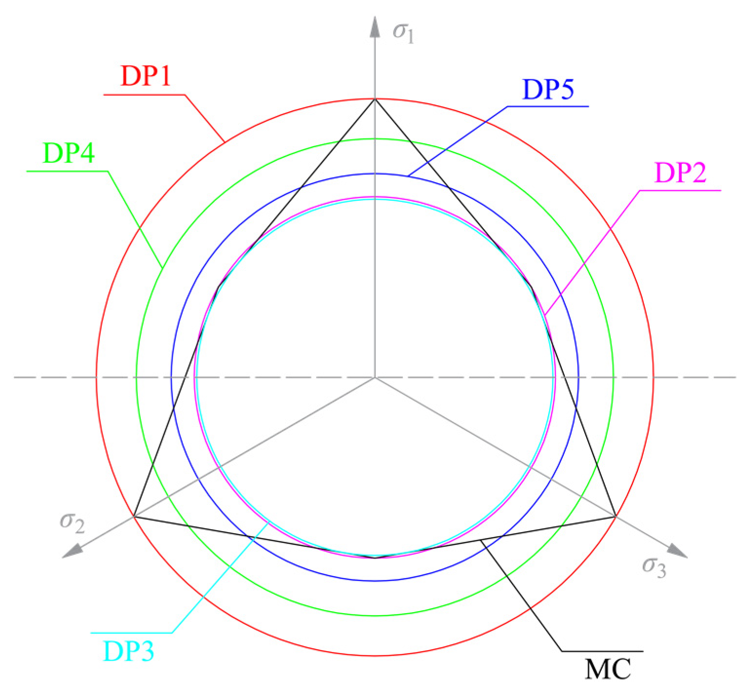
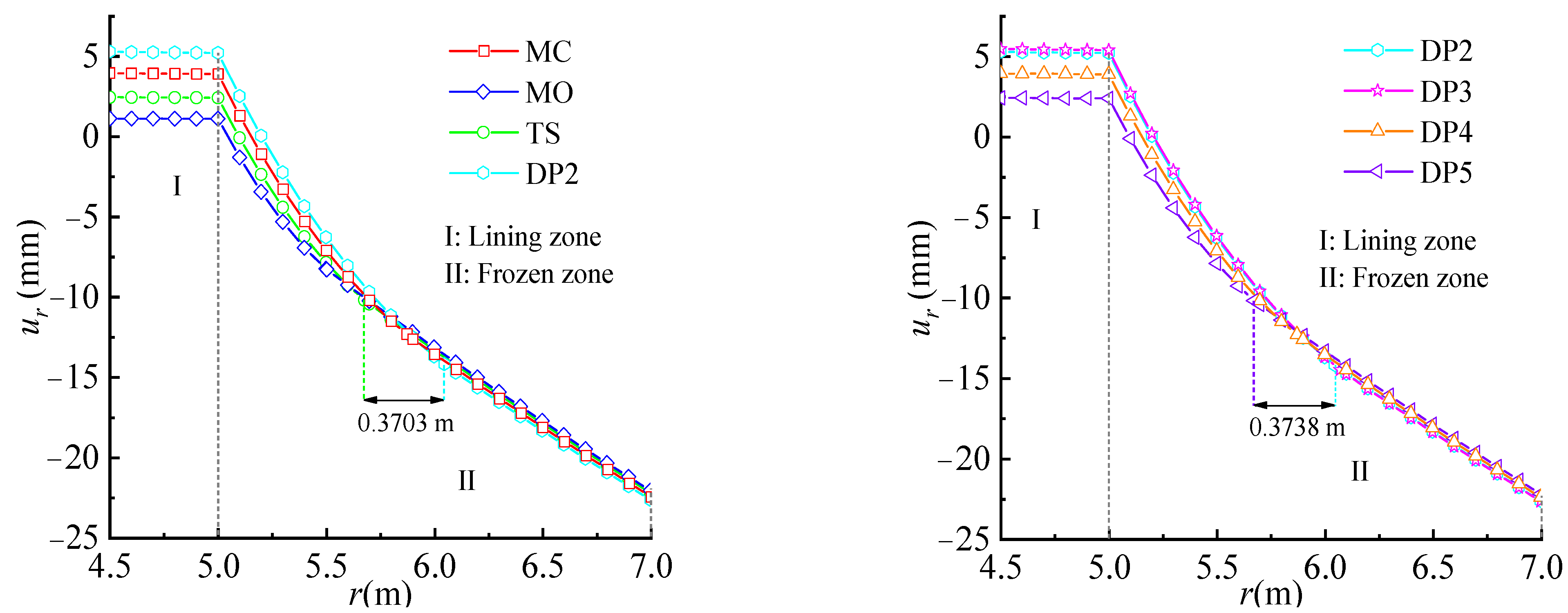
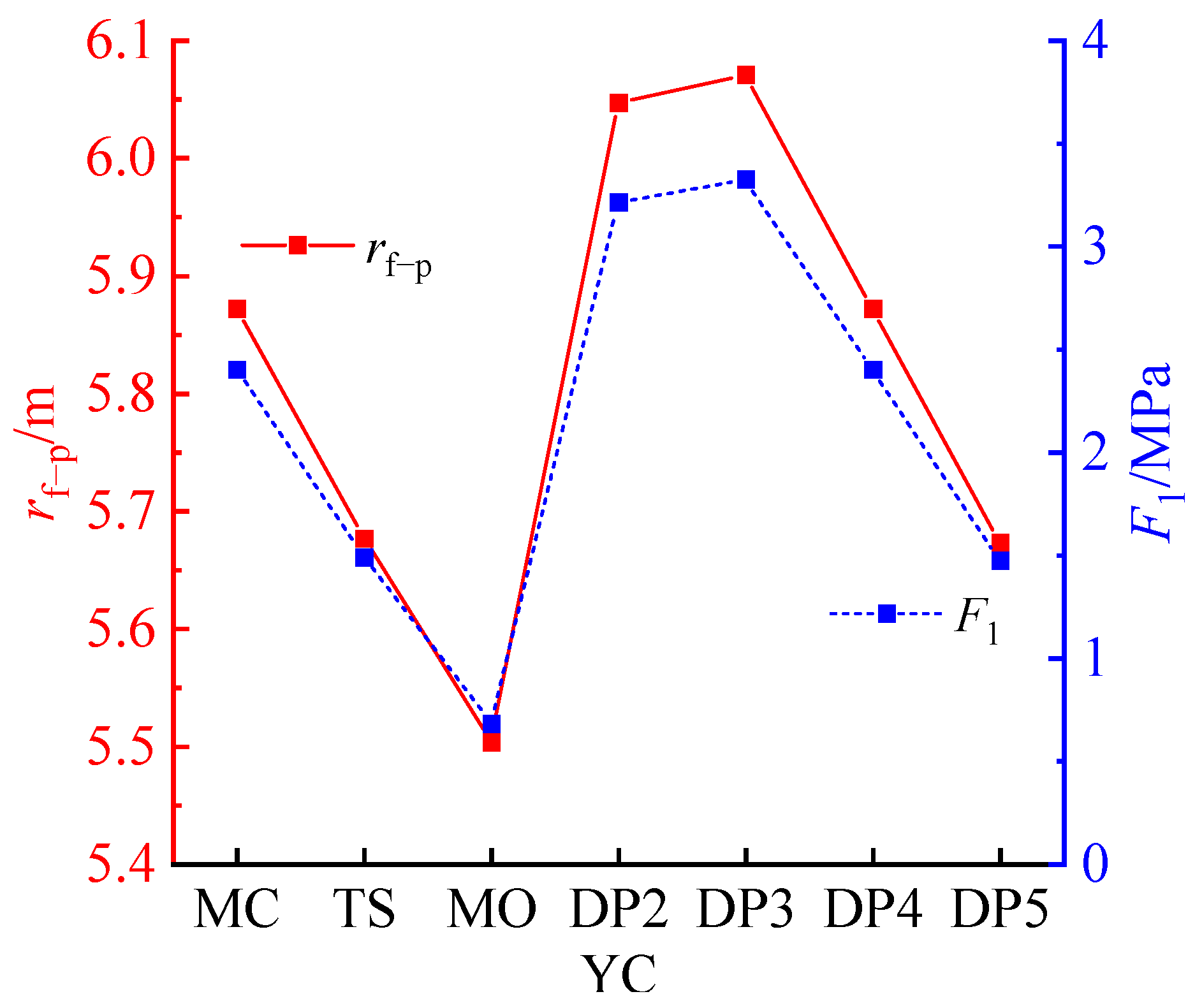
6.1. Yield Criterion of Surrounding Rock

The stress fields of the lined tunnel with different yield criteria are shown in Figure 5 and Table 5. The frozen surrounding rock was assumed to be elastic based on the DP1 yield criterion; thus, the calculated result was ignored. The influence of the yield criterion on the stress field of the lined tunnel, mainly in the circumferential direction in lining zone I and plastic zone II-1, was investigated. The influence on the stress field in other zones can be ignored, especially in unfrozen elastic zone III. For example, in lining zone I, the circumferential stresses calculated using the DP3 criterion were the largest, and the ones with the MO criterion were the smallest. In plastic zone II-1, the MO criterion gave the largest circumferential stresses, while the DP3 criterion gave the smallest.
The displacement fields of the lined tunnel in lining zone I and frozen zone II with different yield criteria are shown in Figure 6. The uniform distribution of the displacement fields in lining zone I was not affected by the selected yield criterion. The influence of the yield criterion on the displacement fields in frozen zone II decreased with the increase in the distance from the tunnel.
The influence of the yield criterion on the plastic-zone radius rf−p and the radial pressure F1 acting on interface I was significant, as shown in Figure 7. The plastic-zone radius rf−p and the radial pressure F1 calculated using the MO criteria were the smallest, and the ones with the DP3 criteria were the largest. The maximum difference between the MO criteria and DP3 criteria for rf−p and F1 reached 0.567 m and 2.64 MPa, respectively.

6.2. Inhomogeneity of Lining

The inhomogeneous coefficient α reflects the variation rate of the elastic modulus of the lining structure along the radial direction. If the inhomogeneous coefficient α = 0, the elastic modulus stayed constant. If the inhomogeneous coefficient α > 0, the elastic modulus increased with the increases in the radius of the lining structure or vice versa. The relation of the stress and displacement fields of the lined tunnel with different inhomogeneous coefficients is shown in Figure 8 and Figure 9, respectively. The influence of the inhomogeneous coefficient α < 0 on the stress and displacement fields of the lined tunnel was significantly larger than when α > 0. The influence of the inhomogeneous coefficient α on the stress and displacement field decreased as the value of α increased. As the inhomogeneous coefficient α increased, the plastic-zone radius rf−p decreased and the radial pressure F1 acting on interface I increased, as shown in Figure 10. When the inhomogeneous coefficient α increased from −5 to 0, the plastic-zone radius rf−p decreased from 6.58 m to 5.74 m. The decreased magnitude was 0.84 m, which is about 14% of rf−p when α = 0.0, while the radial pressure F1 increased from 0.086 to 1.80 MPa; the increased magnitude was 1.714 MPa. When the inhomogeneous coefficient α increased from 0 to 5, the plastic-zone radius rf−p decreased from 5.74 m to 5.63 m. The decreased magnitude was 0.12 m, which is about 2.1% of rf−p when α = 0.0, while the radial pressure F1 increased from 1.80 to 2.21 MPa, with an increased magnitude of 0.41 MPa. Therefore, the influence of positive-value α on rf−p is larger than that of negative-value α (Table 6).

6.3. Radial Pressure Acting on Inner Surface of Lining

The stress and displacement fields of the lined tunnel with respect to the radial pressures acting on the inner surface of the lining are shown in Figure 11. The circumferential stresses and radial displacements in lining zone I and frozen zone II increased with the increase in the radial pressure F0 acting on the inner surface of the lining. As F0 increased, the plastic-zone radius rf−p linearly decreased, while the radial pressure F1 acting on interface I linearly increased, as shown in Figure 12. When the radial pressure F0 increased from 0.0 to 2.0 MPa, the plastic-zone radius rf−p decreased from 5.74 to 5.64 m. The decreased magnitude was 0.1 m, which is about 1.7% of rf−p when F0 = 0.0 MPa, while the radial pressure F1 increased from 1.80 to 2.13 MPa, with an increased magnitude of 0.33 MPa.

7. Conclusions

In the present study, an elasto-plastic mechanical model of a circular lined tunnel in cold regions is proposed, considering several yield criteria for the surrounding rock and the functionally graded feature of the lining. The functionally graded feature is reflected by the variation in the elastic modulus of the lining along the radial direction. Subsequently, the proposed model is compared with an existing model and model tests. Finally, the influence of the main model parameters on the plastic zone, the radial pressure acting on the outer surface of the lining, and the stress and displacement fields is further explored. The key conclusions are summarized as follows:
(1)
The uniform distribution of the displacement fields in lining zone I is not affected by the yield criterion. The influence of the yield criterion on the displacement fields in frozen zone II decreases with the increase in the distance far from the tunnel. The influences of the yield criterion on the plastic-zone radius rf−p and radial pressure F1 acting on interface I are significant. The maximum difference between MO criterion and DP3 criterion for rf−p and F1 reach 0.567 m and 2.64 MPa, respectively.
(2)
The influences of the inhomogeneous coefficient α < 0 on the stress and displacement fields of the lined tunnel are significantly greater than those of α > 0. The influences of the inhomogeneous coefficient α on the stress and displacement fields decrease with the increase in the value of α. As the inhomogeneous coefficient α increases, the plastic-zone radius rf−p decreases, and the radial pressure F1 acting on interface I increases as well.
(3)
The circumferential stresses and radial displacements in lining zone I and frozen zone II increase with the increases in the radial pressure acting on the inner surface of lining F0. As F0 increases, the plastic-zone radius rf−p linearly decreases, and the radial pressure F1 acting on interface I linearly increases as well.

Author Contributions

Conceptualization, J.D., X.Z.; formal analysis, J.D.; investigation, X.Z., H.W.; methodology, J.D., X.Z. and H.W.; validation, X.Z., H.W.; writing, J.D., X.Z. and H.W.; All authors have read and agreed to the published version of the manuscript.

Funding

The authors gratefully acknowledge the financial support by the Key Project of High-speed Rail Joint Fund of the National Natural Science Foundation of China under Grant U1934210, the Major Science and Technology Projects in Xinjiang Uygur Autonomous Region 2020A03003-4, and the China Communications Group’s mega technology research and development project 2017-ZJKJ-01.

Institutional Review Board Statement

Not applicable.

Informed Consent Statement

Not applicable.

Data Availability Statement

The data used to support the findings of this study are available from the corresponding author upon request.

Acknowledgments

We thank the anonymous reviewers and editors for their constructive comments and suggestions to improve the quality of this article.

Conflicts of Interest

The authors declare that they have no conflict of interest.

References

  1. Xu, X.Z.; Wang, J.C.; Zhang, L.X. Frozen Soil Physics; Science Press: Beijing, China, 2001; pp. 1–3. [Google Scholar]
  2. Feng, Q.; Fu, S.G.; Wang, C.X.; Liu, W.W.; Qiao, W.G. Analytical elasto-plastic solution for frost force of cold-region tunnels considering anisotropic frost heave in the surrounding rock. KSCE J. Civ. Eng. 2019, 23, 3831–3842. [Google Scholar] [CrossRef]
  3. Lai, Y.M.; Wu, H.; Wu, Z.W.; Liu, S.Y.; Den, X.J. Analytical viscoelastic solution for frost force in cold-region tunnels. Cold Reg. Sci. Technol. 2000, 31, 227–234. [Google Scholar] [CrossRef]
  4. Yasanthi, R.G.N.; Mehran, B. Application of different data analytics for evaluation of heavy vehicle vulnerability in cold-region rural highways. Transp. Res. Rec. J. Transp. Res. Board 2023, 2677, 282–298. [Google Scholar] [CrossRef]
  5. Lai, Y.M.; Wu, Z.W.; Zhu, Y.L.; Zhu, L.N. Elastic visco-plastic analysis for earthquake response of tunnels in cold regions. Cold Reg. Sci. Technol. 2000, 31, 175–188. [Google Scholar] [CrossRef]
  6. Feng, Q.; Jiang, B.S.; Zhang, Q.; Wang, L.P. Analytical elasto-plastic solution for stress and deformation of surrounding rock in cold region tunnels. Cold Reg. Sci. Technol. 2014, 108, 59–68. [Google Scholar] [CrossRef]
  7. Feng, Q.; Liu, W.W.; Jiang, B.S. Analytical solution for the stress and deformation of rock surrounding a cold-regional tunnel under unequal compression. Cold Reg. Sci. Technol. 2017, 139, 1–10. [Google Scholar] [CrossRef]
  8. Du, J.M.; Fang, Q.; Wang, G.; Wang, J. Analytical solution of a circular lined tunnel with alterable mechanical property under hydrostatic stress and internal pressure. J. Cent. South Univ. 2022, 29, 2757–2770. [Google Scholar] [CrossRef]
  9. Lai, Y.M.; Wu, Z.W.; Zhu, Y.L.; Zhu, L.N. Nonlinear analysis for the coupled problem of temperature, seepage and stress fields in cold-region tunnels. Tunn. Undergr. Space Technol. 1998, 13, 435–440. [Google Scholar] [CrossRef]
  10. Lai, Y.M.; Zhang, X.F.; Yu, W.B.; Zhang, S.J.; Liu, Z.Q.; Xiao, J.Z. Three-dimensional nonlinear analysis for the coupled problem of the heat transfer of the surrounding rock and the heat convection between the air and the surrounding rock in cold-region tunnel. Tunn. Undergr. Space Technol. 2005, 20, 323–332. [Google Scholar] [CrossRef]
  11. Gao, G.Y.; Chen, Q.S.; Zhang, Q.S.; Chen, G.Q. Analytical elasto-plastic solution for stress and plastic zone of surrounding rock in cold region tunnels. Cold Reg. Sci. Technol. 2012, 72, 50–57. [Google Scholar] [CrossRef]
  12. Zhao, X.; Yang, X.H.; Zhang, H.W.; Lai, H.P.; Wang, X.Y. An analytical solution for frost heave force by the multifactor of coupled heat and moisture transfer in cold-region tunnels. Cold Reg. Sci. Technol. 2020, 175, 103077. [Google Scholar] [CrossRef]
  13. Zheng, H.; Kanie, S.J. Combined thermal-hydraulic-mechanical frost heave model based on Takashi’s equation. J. Cold Reg. Eng. 2014, 29, 04014019. [Google Scholar] [CrossRef]
  14. Feng, Q.; Yang, Z.D.; Liu, W.W.; Zhao, W.S. Experimental study of the anisotropic frost heave characteristics of rock surrounding tunnels in cold regions. J. Cold Reg. Eng. 2021, 35, 04021014. [Google Scholar] [CrossRef]
  15. Zheng, H.; Kanie, S.J.; Niu, F.J.; Li, A.Y. Three-dimensional frost heave evaluation based on practical Takashi’s equation. Cold Reg. Sci. Technol. 2015, 118, 30–37. [Google Scholar] [CrossRef]
  16. Huang, J.H.; Xia, C.C.; Han, C.L. Analytical solution of frost heave force acting on cold-region tunnel liner considering anisotropy frost heave of surrounding rock. Chin. J. Rock Mech. Eng. 2015, 34, 3666–3774. [Google Scholar] [CrossRef]
  17. Xia, C.C.; Lv, Z.T.; Li, Q.; Huang, J.H.; Bai, X.Y. Transversely isotropic frost heave of saturated rock under unidirectional freezing condition and induced frost heaving force in cold region tunnels. Cold Reg. Sci. Technol. 2018, 152, 48–58. [Google Scholar] [CrossRef]
  18. Liu, W.W.; Feng, Q.; Fu, S.G.; Wang, C.X. Elasto-plastic solution for cold-regional tunnels considering the compound effect of non-uniform frost heave, supporting strength and supporting time. Tunn. Undergr. Space Technol. 2018, 82, 293–302. [Google Scholar] [CrossRef]
  19. Lv, Z.T.; Xia, C.C.; Wang, Y.S.; Luo, J. Analytical elasto-plastic solution of frost heaving force in cold region tunnels considering transversely isotropic frost heave of surrounding rock. Cold Reg. Sci. Technol. 2019, 163, 87–97. [Google Scholar] [CrossRef]
  20. Koizumi, M. FGM activities in Japan. Compos. Part B Eng. 1997, 28, 1–4. [Google Scholar] [CrossRef]
  21. Batra, R.C. Optimal design of functionally graded incompressible linear elastic cylinders and spheres. AIAA J. 2008, 46, 2050–2057. [Google Scholar] [CrossRef] [Green Version]
  22. Xiang, H.J.; Shi, Z.F.; Zhang, T.T. Elastic analyses of heterogeneous hollow cylinders. Mechanics Research Communications 2006, 33, 681–691. [Google Scholar] [CrossRef]
  23. Tutuncu, N. Stresses in thick-walled FGM cylinders with exponentially-varying properties. Eng. Struct. 2007, 29, 2032–2035. [Google Scholar] [CrossRef]
  24. Stampouloglou, I.H.; Theotokoglou, E.E. The radially nonhomogeneous thermoelastic axisymmetric problem. Int. J. Mech. Sci. 2017, 120, 311–321. [Google Scholar] [CrossRef]
  25. Shi, Z.F.; Zhang, T.T.; Xiang, H.J. Exact solutions of heterogeneous elastic hollow cylinders. Compos. Struct. 2007, 79, 140–147. [Google Scholar] [CrossRef]
  26. Yang, Y.Y. Time-dependent stress analysis in functionally graded materials. Int. J. Solids Struct. 2000, 37, 7593–7608. [Google Scholar] [CrossRef]
  27. Tutuncua, N.; Ozturk, M. Exact solutions for stresses in functionally graded pressure vessels. Compos. Part B Eng. 2001, 32, 683–686. [Google Scholar] [CrossRef]
  28. Çallıoğlu, H.; Sayer, M.; Demir, E. Elastic–plastic stress analysis of rotating functionally graded discs. Thin-Walled Struct. 2015, 94, 38–44. [Google Scholar] [CrossRef]
  29. Zhang, N.; Lu, A.Z.; Li, C.C.; Zhou, J.; Wang, S.; Chen, X. Support performance of functionally graded concrete lining. Constr. Build. Mater. 2017, 147, 35–47. [Google Scholar] [CrossRef]
  30. Zhang, T.T.; Cui, Z.D.; Wang, S.Y. Deformation properties of functionally graded lining in deeply buried subway tunnel. J. Tianjin Univ. (Sci. Technol.) 2019, 52, 135–140. [Google Scholar]
  31. Sun, B. Model test study of frost heaving pressures in tunnels excavated in fractured rock mass in cold regions. Sci. Cold Arid Reg. 2010, 2, 405–410. [Google Scholar]
  32. Du, J.M.; Fang, Q.; Wang, G.; Zhang, D.L.; Chen, T.L. Fatigue damage and residual life of secondary lining of high-speed railway tunnel under aerodynamic pressure wave. Tunn. Undergr. Space Technol. 2021, 111, 103851. [Google Scholar] [CrossRef]
  33. Du, J.M.; Fang, Q.; Wang, J.; Wang, G. Influences of high-speed train speed on tunnel aerodynamic pressures. Appl. Sci. 2022, 12, 303. [Google Scholar] [CrossRef]
  34. Sadd, M.H. Elasticity Theory: Applications, and Numerics; Academic Press: Cambridge, MA, USA, 2005. [Google Scholar] [CrossRef]
  35. Levin, V.A.; Podladchikov, Y.Y.; Zingerman, K.M. An exact solution to the Lame problem for a hollow sphere for new types of nonlinear elastic materials in the case of large deformations. Eur. J. Mech. A/Solids 2021, 90, 104345. [Google Scholar] [CrossRef]
  36. Huang, X.J.; Zhang, J.X.; Yang, L.; Yang, S.K.; Wang, X.L. Elasto-plastic analysis of the surrounding rock mass in circular tunnel based on the generalized nonlinear unified strength theory. Int. J. Min. Sci. Technol. 2016, 26, 819–823. [Google Scholar] [CrossRef]
  37. Al-Ajmi, A.M.; Zimmerman, R.W. Relation between the Mogi and the Coulomb failure criteria. Int. J. Rock. Mech. Min. Sci. 2005, 42, 431–439. [Google Scholar] [CrossRef]
Figure 1. Schematic diagram of the proposed mechanical model.
Sustainability 15 11577 g001
Figure 2. Schematic diagram of Drucker–Prager yield criterion.
Sustainability 15 11577 g002
Figure 3. Comparison of results between the proposed and the existing mechanical models [19].
Sustainability 15 11577 g003
Figure 4. Comparison of results obtained with the proposed model and the model test.
Sustainability 15 11577 g004
Figure 5. Stress fields of lined tunnel for different yield criteria.
Sustainability 15 11577 g005
Figure 6. Displacement fields of lined tunnel for different yield criteria.
Sustainability 15 11577 g006
Figure 7. Influence of yield criterion on plastic-zone radius rf−p and radial pressure F1.
Sustainability 15 11577 g007
Figure 8. Stress fields of lined tunnel for different inhomogeneous coefficients (α). (a) α < 0 (b) α > 0.
Sustainability 15 11577 g008
Figure 9. Displacement fields of lined tunnel for different inhomogeneous coefficients (α). (a) α < 0 (b) α > 0.
Sustainability 15 11577 g009
Figure 10. Influence of inhomogeneous coefficient α on plastic-zone radius rf−p and radial pressure F1.
Sustainability 15 11577 g010
Figure 11. Stress and displacement fields of lined tunnel for different radial pressures acting on inner surface of lining (F0). (a) Stress fields of lined tunnel. (b) Displacement fields of lined tunnel.
Sustainability 15 11577 g011
Figure 12. Influence of radial pressure acting on inner surface of lining F0 on plastic-zone radius rf−p and radial pressure F1.
Sustainability 15 11577 g012
Table 1. Expressions for A1 and A2 for different yield criteria.
Yield CriterionA1A2
Mohr–Coulomb (MC) 1 + sin φ 1 sin φ 2 c cos φ 1 sin φ
Unified Strength Theory (UST) ( 2 + b ) + ( 2 + 3 b ) sin φ ( 2 + b ) ( 1 sin φ ) 4 ( 1 + b ) c cos φ ( 2 + b ) ( 1 sin φ )
Mogi-Coulomb (MO) [37] 3 + 2 sin φ 3 2 sin φ 4 c cos φ 3 2 sin φ
Drucker–Prager
(DP)
DP1 2 sin φ 3 ( 3 sin φ ) 6 c cos φ 3 ( 3 sin φ )
DP2 2 sin φ 3 ( 3 + sin φ ) 6 c cos φ 3 ( 3 + sin φ )
DP3 sin φ 3 3 + sin 2 φ 3 c cos φ 3 3 + sin 2 φ
DP4 2 3 sin φ 2 3 π ( 9 sin 2 φ ) 6 3 c cos φ 2 3 π ( 9 sin 2 φ )
DP5 sin φ 3 c cos φ
Table 2. Calculated parameters of mechanical models [19].
ParameterUnitValue
rL−im4.5
rL−o = rf−im5.0
ELGPa28.0
uL-0.16
EfGPa7.8
uf-0.35
ηv-0.0165
kf-1.0
cMPa1.7
φ°45
hf-3.0
rf−o = ruf−im7.0
EufGPa4.6
uuf-0.33
P0MPa2.5
δ-0.0
Table 3. Model test parameters [31].
ParameterUnitValue
rL−im0.08
rL−o = rf-im0.095
ELGPa615.0
uL-0.205
EfGPa48.5
uf-0.42
ηv-0.0203
ckPa5.0
φ°38
hf-2.37
rf−o = ruf−im0.10
EufGPa37.0
uuf-0.41
P0kPa5.639
δ-0.0
Table 4. Results obtained with proposed model and model test and corresponding difference.
Anisotropic frost heave coefficient kf1.01.52.02.53.0
b0.0Proposed model (kPa)51.6453.0953.7354.4654.96
Model-test average value (kPa)47.447.447.447.447.7
Difference (%)8.9512.0013.3514.8915.22
b0.25Proposed model (kPa)47.4548.43494450.0850.43
Model-test average value (kPa)47.447.447.447.447.7
Difference (%)0.112.174.305.655.72
b0.50Proposed model (kPa)44.2445.5446.4546.9147.39
Model-test average value (kPa)47.447.447.447.447.7
Difference (%)6.673.922.001.030.65
b0.75Proposed model (kPa)41.9643.1743.8844.4545.03
Model-test average value (kPa)47.447.447.447.447.7
Difference (%)11.488.927.426.225.60
b1.00Proposed model (kPa)40.2741.6442.1542.8143.09
Model-test average value (kPa)47.447.447.447.447.7
Difference (%)15.0412.1511.089.689.66
Table 5. Stress values for different yield criteria.
Yield CriteriaMCTSMODP2DP3DP4DP5
r (m)4.5σr (MPa)0.00.00.00.00.00.00.0
σq (MPa)10.116.282.8813.5313.9910.116.21
r (m)5.0σr (MPa)0.960.600.271.291.330.960.59
σq (MPa)9.155.682.6112.2412.679.155.62
r (m)6.0σr (MPa)3.253.193.143.443.523.253.18
σq (MPa)19.7419.8419.9219.5019.4219.7419.85
r (m)7.0σr (MPa)5.435.405.375.485.495.445.40
σq (MPa)17.5517.6317.6917.4617.4617.5517.63
r (m)8.0σr (MPa)4.394.374.344.3040344.404.36
σq (MPa)−2.40−2.37−2.34−2.43−2.43−2.40−2.36
r (m)10.0σr (MPa)3.173.153.143.193.203.173.15
σq (MPa)−1.17−1.53−1.14−1.191.20−1.17−1.15
Table 6. Stress values for different inhomogeneous coefficients (α).
Inhomogeneous Coefficients (α)−2.0−1.0−0.50.01.02.04.0
r/rL−i (m)4.5σr (MPa)0.00.00.00.00.00.00.0
σq (MPa)2.475.236.587.598.378.277.48
r/rL−i (m)5.0σr (MPa)0.210.470.610.720.840.870.88
σq (MPa)1.814.275.656.878.419.2110.27
r/rL−i (m)6.0σr (MPa)2.422.632.973.213.433.493.51
σq (MPa)20.3820.7720.2119.8119.4419.3419.32
r/rL−i (m)7.0σr (MPa)4.485.045.265.415.555.595.60
σq (MPa)19.5018.3717.9217.6117.3217.2417.22
r/rL−i (m)8.0σr (MPa)3.664.094.264.384.484.514.45
σq (MPa)−1.66−2.09−2.26−2.38−2.49−2.51−2.52
r/rL−i (m)10.0σr (MPa)2.712.983.093.163.233.253.25
σq (MPa)−0.71−0.98−1.08−1.16−1.23−1.25−1.25
Disclaimer/Publisher’s Note: The statements, opinions and data contained in all publications are solely those of the individual author(s) and contributor(s) and not of MDPI and/or the editor(s). MDPI and/or the editor(s) disclaim responsibility for any injury to people or property resulting from any ideas, methods, instructions or products referred to in the content.

