Article

Seismic Stability Analysis of Tunnel Faces in Heterogeneous and Anisotropic Soils Using Modified Pseudodynamic Method

1
Huaiyin Institute of Technology, Huai’an 223003, China
2
School of Civil Engineering, Central South University, Changsha 410083, China
3
Geotechnical Research Institute, Hohai University, Nanjing 210098, China
*
Author to whom correspondence should be addressed.
Sustainability 2023, 15(14), 11083; https://doi.org/10.3390/su151411083
Submission received: 18 May 2023 / Revised: 17 June 2023 / Accepted: 7 July 2023 / Published: 15 July 2023
(This article belongs to the Special Issue Advances in Dynamic Hazards Prevention in Underground Mines)

Abstract

:
This work assesses the seismic stability of tunnel faces advanced in heterogeneous and anisotropic soils based on the plastic limit theorem. A discretized kinematic velocity field respecting the normal flow rule is generated via a point-to-point discretization technique. The distribution of soil parameters in the depth direction including cohesion, friction angle, and unit weight are considered by four kinds of profiles. The variation in cohesion with shear direction caused by consolidation and sedimentation is considered by including an anisotropy coefficient. The seismic acceleration is represented by the modified pseudodynamic method (MPD) rather than the conventional pseudodynamic method (CPD). Based on the energy equilibrium equation, an upper-bound solution is derived. The accuracy and rationality of the proposed procedure are substantiated by comparing with the solutions obtained by conventional log-spiral mechanism and CPD. A parametric study indicates that nonlinear profiles tend to predict a smaller required face pressure than the constant and linear profiles due to the convexity of nonlinear profiles. The over-consolidated soil is more sensitive to the anisotropy coefficient than normally consolidated soil. Moreover, the adverse effect of horizontal seismic acceleration is much greater than that of vertical acceleration, and the resonance effect is more prone to happen, especially for shallow-buried tunnels.

1. Introduction

The acceleration of urbanization puts forward a higher demand for the construction of underground transportation in cities where the tunnel plays a significant role in the connection of different regions. In the excavation of tunnels and underground cavities, the stability and safety of excavation faces are important prerequisites for the smooth penetration and timely delivery of the tunnel. Numerous contributions have been made to predict the required support pressure and to ensure safety by various methods [1,2], such as the limit equilibrium method [3,4,5,6], numerical simulation [7,8,9], limit analysis method, and their combinations [10,11,12,13]. Compared with the limit analysis method, the limit equilibrium method, as a classic theoretical method, solves the stability problems from the viewpoint of static equilibrium. It usually assumes a specific failure surface, such as a circular shape, log-spiral surface, and cylinder, and then presumes a local stress field to the slip surface. Finally, based on the stress analysis of the whole failure block, the static equilibrium equation is established, and the corresponding limit equilibrium solution is obtained. However, the assumption of the local stress field on the failure surface cannot be extended to the whole study area, and the stress state beyond the presumed area is not exactly known; indeed, it does not strictly meet the definition of the lower-bound stress field, and such a limit equilibrium solution is also called partial stress solution. Although the derivation of the limit equilibrium solution uses the upper-bound failure mechanism and derives the least upper bound, it also does not satisfy the definition of the upper-bound mechanism.
The limit analysis method, relying on its rigorous and systematic theorem, has gradually been accepted by scholars and engineers in recent decades [14,15,16,17,18]. The difficulty of the lower-bound analysis exists in the establishment of the statically permissible stress field; for this reason, the construction of the appropriate stress field is generally performed with the help of finite element software. However, the kinematic method deals with stability problems from the perspective of kinematics and avoids complicated stress analysis. It assumes a kinematically admissible velocity field, namely, the failure mechanism, and considers the failure block as a rigid body. Then, the limit failure load is derived from the equilibrium between the rate of internal energy dissipated in the failure surface and the rate of external work. Regarding the stability analysis of excavation faces, Leca and Dormieux [19] first proposed a truncated cone mechanism to predict the critical support pressure of tunnel faces, based on which Mollon et al. [20] modified this mechanism by adding the number of blocks and achieved a good solution. Subrin and Wong [21] proposed a new three-dimensional curvilinear cone failure mechanism to portray the active failure of tunnel faces. However, these contributions are based on the assumption of uniformity and isotropy of soils. The impact of variation in soil properties with depth and direction resulting from the geologic sedimentation and consolidation was often ignored. Unfortunately, depending on the conventional upper-bound analysis, it is difficult to establish a kinematic velocity field consistent with the variation in soil properties. Therefore, the discretization strategy is proposed to deal with such problems. It was first developed by Mollon et al. [22] to improve the failure mechanism and make the failure cover the entire tunnel face. Such an improvement allows the stability analysis to be applied to more complex situations, such as seepage conditions, earthquake action, complicated stratigraphic conditions, and nonlinearity of soil strength [23,24,25,26,27,28,29].
Then, the discretization technique is extensively used to address stability problems under nonuniform soils or earthquake loading. Chen et al. [30] investigated the face stability of the shallow tunnel in heterogeneous and anisotropic soils considering the passive failure of tunnel faces. Qin and Chian [31] applied this method to access the slope stability and calculated the ultimate bearing capacity of slopes suffering from seismic loading in heterogeneous soils. It only considered the heterogeneity of soil properties as a simple linear variation with depth; the nonlinear variation in soil parameters and the non-uniformity of the unit weight were not involved. Zhong and Yang [32,33] extended the pseudodynamic method to the evaluation of the seismic stability of deeply buried tunnel faces. However, the seismic acceleration is represented by the conventional pseudodynamic method (CPD), which violates the zero-stress boundary condition and ignores the damping of materials; moreover, the acceleration amplitude is assumed to be a constant distribution.
Therefore, in this paper, a new modified pseudodynamic method (MPD) that remedies the above deficiencies is adopted to characterize the variation in seismic acceleration with time and space. A discretized mechanism that consists of a series of discretized points is generated via a point-to-point discretization method to adapt the variation in soil properties with depth. According to the equilibrium between the internal and external work rates, the upper-bound solution of the required face pressure is obtained in this work. The heterogeneity of soil properties is analyzed by encompassing the cohesion, friction angle, and unit weight. Four kinds of distribution profiles are assumed to describe the variation in soil parameters with depth. The anisotropy of cohesion is considered by defining a coefficient k = cv/ch.

2. Methodology

2.1. Modified Pseudodynamic Method

The classic wave equation is derived based on the elastic medium assumption, which is not suitable for soil materials. Therefore, the Kelvin–Voigt viscoelastic model is used to model the constitutive relationship of soil materials for studying the seismic response of soils in the vicinity of the tunnel face under earthquake excitation. According to Kramer [34], the vibration displacement of particles in the viscoelastic medium can be decomposed into horizontal ( u h ) and vertical ( u v ) components induced by shear and primary waves; therefore, the wave equation is written as the following partial differential equations
ρ 2 u h t 2 = G 2 u h z 2 + η 2 3 u h t z 2
ρ 2 u v t 2 = λ + 2 G 2 u v z 2 + η 1 + 2 η 2 3 u v t z 2
where ρ denotes medium density; η 1 and η 2 are viscosity; λ and G are Lamé constants. Assuming a base shaking in the horizontal direction, Bellezza [35] derived the explicit expression of the displacement from the above equations, based on the zero-stress boundary condition at the ground surface and the initial displacement condition u h b = u h 0 cos ϖ t at the base y = 0 . The horizontal vibration displacement of particles in the viscoelastic medium is presented as
u h y , t = u h 0 C S 2 + S S 2 C S C S Z + S S S S Z cos ϖ t + S S C S Z C S S S Z sin ϖ t
Calculating the second derivative of formula Equation (3) concerning time, and retaining the real part, one can yield the seismic acceleration at time t and height y
a h y , t = k h g C S 2 + S S 2 C S C S Z + S S S S Z cos ϖ t + S S C S Z C S S S Z sin ϖ t
where k h is the horizontal seismic coefficient defined by k h g = ϖ 2 u h 0 ; and the expressions of intermediate items C S , S S   C S Z , and S S Z take the forms
C S = cos y s 1 cosh y s 2
S S = sin y s 1 sinh y s 2
C S Z = cos y s 1 C + D y C + D cosh y s 2 C + D y C + D
S S Z = sin y s 1 C + D y C + D sinh y s 2 C + D y C + D
in which
y S 1 = ϖ C + D V s 1 + 4 ξ 2 + 1 2 1 + 4 ξ 2 1 / 2
y S 2 = ϖ C + D V s 1 + 4 ξ 2 1 2 1 + 4 ξ 2 1 / 2
Similarly, the vertical vibration displacement of particles in the viscoelastic medium is obtained by applying the initial vertical displacement u v b = u v 0 cos ϖ t
u v y , t = u v 0 C P 2 + S P 2 C P C P Z + S P S P Z cos ϖ t + S P C P Z C P S P Z sin ϖ t
Calculating the second derivative of formula Equation (11) concerning time, and retaining the real part, the seismic acceleration at time t and height y reads
a v y , t = k v g C P 2 + S P 2 C P C P Z + S P S P Z cos ϖ t + S P C P Z C P S P Z sin ϖ t
where k v denotes the vertical seismic coefficient defined by k v g = ϖ 2 u v 0 ; and the expressions of intermediate items C P , S P   C P Z , and S P Z take the forms
C P = cos y P 1 cosh y P 2
S P = sin y P 1 sinh y P 2
C P Z = cos y P 1 C + D y C + D cosh y P 2 C + D y C + D
S P Z = sin y P 1 C + D y C + D sinh y P 2 C + D y C + D
where
y P 1 = ϖ C + D V p 1 + 4 ξ 2 + 1 2 1 + 4 ξ 2 1 / 2
y P 2 = ϖ C + D V p 1 + 4 ξ 2 1 2 1 + 4 ξ 2 1 / 2

2.2. Heterogeneity and Anisotropy Materials

In geotechnical engineering, soil materials are assumed to be homogeneous and isotropic to facilitate analysis and simplify calculation in most cases. However, due to natural deposition, artificial surcharge, and other factors, soils often behave with certain strength heterogeneity along depth and anisotropy with shearing direction. It is of great theoretical and practical meaning to study the stability of excavation faces under the condition of strength heterogeneity and anisotropy. The common cognition takes the distribution of values of strength parameters as linear variation with depth, as indicated in Figure 1c; it is too simple and not comprehensive, and therefore, a polynomial relationship f y i is assumed herein. The heterogeneous parameters involved in this work include c, φ , and γ , and the corresponding values at a random height y i read
c i = f α y i = k 1 y i α + b 1 φ i = f α y i = k 2 y i α + b 2 γ i = f α y i = k 3 y i α + b 3
where α is the exponent of the power function, with α = 0 ,   1 ,   2 ,   3 corresponding to the distribution of parameters in average value, linear variation, quadratic variation, and cubic variation, respectively. k 1 , k 2 , k 3 and b 1 , b 2 , b 3 are coefficients that need to be determined based on the initial parameters at yi = C + D and yi = 0.
The strength anisotropy of soils is mainly reflected in cohesion. The cohesion of most soils is anisotropic with respect to the shear direction, Casagrande and Carrillo [36] investigated the variation in cohesion at a certain point in soils with direction, and they found the variation in cohesion takes the following trend, as shown in Figure 1d.
c κ = c h + c v c h cos 2 κ
where c κ is defined as the cohesion at the slip surface where the principal stress direction makes an angle of κ with vertical direction. Based on the geometry relationship in Figure 2b, κ = π / 2 θ φ i ψ in failure surface where ψ is the angle between failure surface and major principal stress, and it usually adopts ψ = π / 4 φ i / 2 ; c h and c v represent the cohesions in horizontal and vertical directions, respectively. Introducing a coefficient k = c v / c h , and considering the heterogeneity, then Equation (20) becomes
c i κ = c i 1 + 1 k k cos 2 κ

3. Determination of the Discretized Mechanism

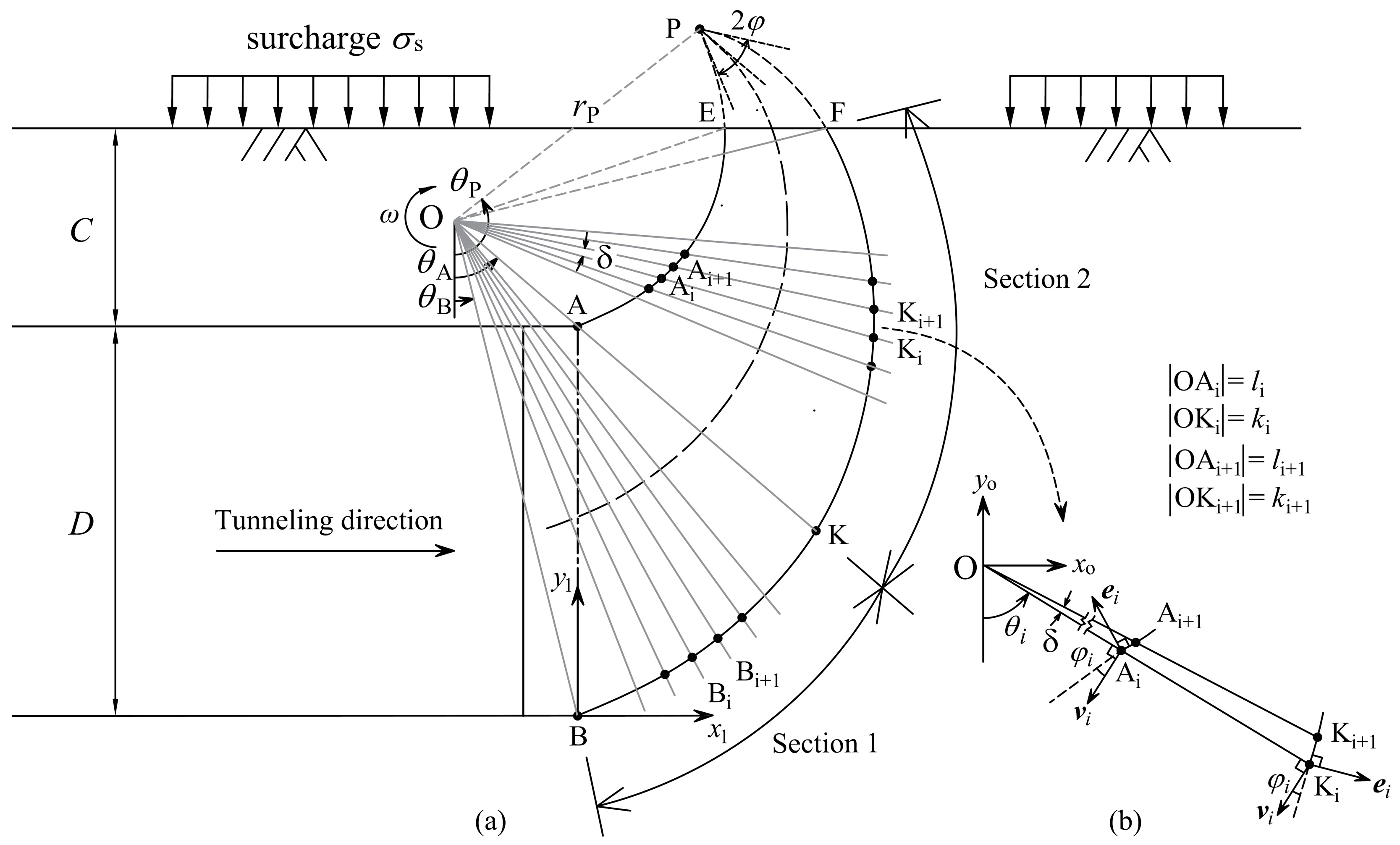
This work aims to predict the required support pressure of shallow-buried tunnels in the heterogeneous and anisotropic soil materials governed by the Mohr–Coulomb failure criterion. To consider the nonuniform feature of the internal friction angle, a discretization technique is used herein to generate the potential failure mechanism that extends to the surface, as illustrated in Figure 2. Failure surfaces start from crown A and invert B, and they finally intersect with the surface at points E and F, respectively. Due to the existence of the excavation face, the failure mechanism is truncated. Therefore, the failure mechanism is divided into two sections by the radial plane passing through points O and A, and the generation process is implemented in two steps.
Taking point B as the origin of the Cartesian coordinate system and point O as the origin of the polar coordinate system, two sets of coordinate systems are established. In Sections 1 and 2, a series of radial lines passing through polar origin O are plotted, and the angle between successive radial lines is identical. Citing Section 2 for an example, the point K i x i , y i is given as the starting point, and the next point is K i + 1 x i + 1 , y i + 1 ; the primary mission is to determine the coordinate of the point K i + 1 x i + 1 , y i + 1 . As presented in Figure 2b, the normal flow rule requests an angle of φ i between the slip surface and the corresponding velocity, and afterward, based on the sine theorem in triangular element OKiKi+1, the length of radial line OKi+1 therefore takes the form
r i + 1 = r i cos φ i cos φ i δ
with a length of radial line OKi being
r i = x i x o 2 + y i y o 2
The coordinate of point Ki+1 in the xoOyo system yields
x i + 1 = r i + 1 sin θ i + δ y i + 1 = r i + 1 cos θ i + δ
Transforming the coordinate of Ki+1 in the xoOyo coordinate system into that in the x1Oy1 coordinate system, the coordinates of the next point are obtained
x i + 1 = r i + 1 sin θ i + δ r B sin θ B y i + 1 = r i + 1 cos θ i + δ + r B cos θ B
Implementing the aforementioned procedure in turn, the failure surface consisting of a series of discretized points is generated. The generation of the upper boundary AE follows the same procedure as lower boundary BF except for substituting Equation (22) with Equation (26).
r i + 1 = r i cos φ i cos φ i + δ
The rotation center O of the failure mechanism is controlled by two dependent angular variables θ A and θ B . r A and r B , shown in Equation (25), are defined as the initial radius, and based on the geometric relationship, they are calculated as
r A = C sin θ B sin θ A     θ B r B = C sin π     θ A sin θ A     θ B
Following the aforementioned procedure, the last two points of boundaries might not exactly locate the ground surface when the generation successfully finishes, and thus, the accurate coordinates of intersection points are determined by linear interpolation. As mentioned above, the parameter δ governs the density of discretized points and affects the accuracy of the solution. A smaller δ results in a closer match to the log-spiral mechanism. The appropriate value of the incremental angle will be discussed in detail.

4. Face Stability Analysis by Kinematic Theorem

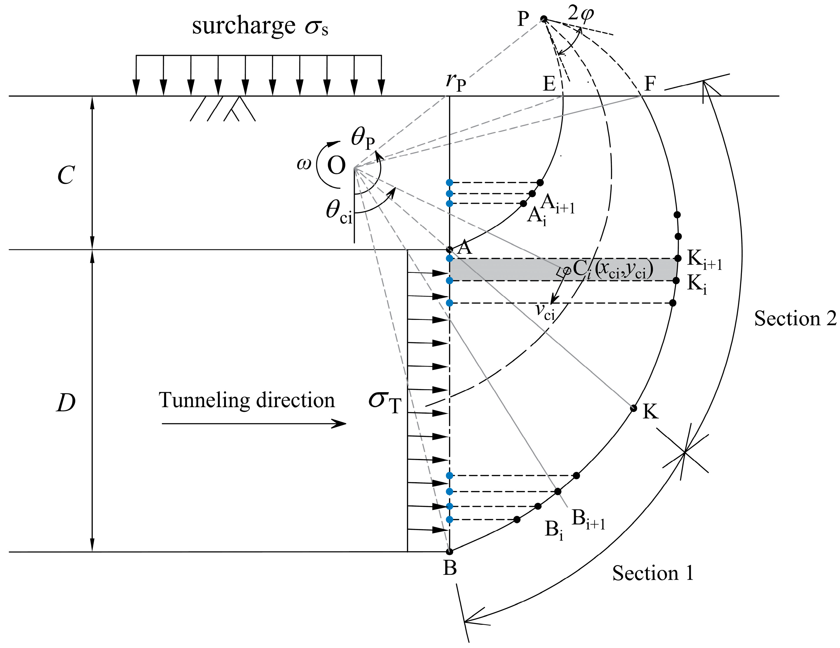
Section 3 interrupted the calculation of the discretized points for shallow-buried tunnels in detail. Given a random initial point, the coordinate of the next point can be determined by the procedure proposed in Section 3. Such a point-to-point method discretizes the failure surfaces and makes the consideration of heterogeneity possible, as illustrated in Figure 3. In the computation of rates of work, the direct integral method does not apply to the discontinuous boundaries consisting of discretized points, and therefore, the classic superposition method is adopted in this work. Taking the plane where the tunnel face is located as the projection plane, termed as Π , and projecting all discretized points onto the Π plane, then two adjacent points and their projection points form a trapezoidal element. As the angle increment δ is small enough, the thickness of such a trapezoidal element becomes infinitesimal, so that the shear strength parameters can be taken as uniformly distributed in the trapezoidal element. Taking a trapezoidal element K i K i + 1 P i P i + 1 , as shown in the shaded area of Figure 3, for instance, the procedure of calculation for the rate of work produced by gravity is elaborated as follows.
Using all the discretized points located in discontinuity BF, then total rates of work by self-gravity yield the following expression
W ˙ G = i ω γ y i S i x o x ci 2 + y o y ci 2 sin θ ci
where γ i is the unit weight of the ith trapezoidal element at height y i , and θ ci is the angle between the gravity direction and line OCi. S i is the area of the ith trapezoidal element. x ci , y ci denotes the coordinates of the centroid of the ith element.
x ci = x i 2   +   x i x i + 1   +   x i + 1 2 3 x i   +   x i + 1 y ci = x i y i + 1   +   x i + 1 y i   +   2 x i y i   +   2 x i + 1 y i + 1 3 x i   +   x i + 1
However, rates of work in Equation (28) contain the rate of work of block AEN, which does not belong to the failure block of the tunnel face and needs to be removed. The rate of work of block AEN can be calculated analogously to Equation (28), and the procedure is not repeated herein.
In seismic stability analysis, the earthquake affects the stability of geotechnical structures from two aspects, increasing the driving force and decreasing the shear strength of soils, but in this work, only the former is considered. The positive directions of horizontal and vertical accelerations are defined as follows: leftwards (←) and downwards (↓). In each element, calculating the inertial force based on the MPD, the rate of inertial forces can be calculated as
W ˙ G h = i ω γ y i S i x o x ci 2 + y o y ci 2 cos θ ci     k h C S 2 + S S 2 C S C S Z + S S S S Z cos ϖ t + S S C S Z C S S S Z sin ϖ t
W ˙ G v = i ω γ y i S i x o x ci 2 + y o y ci 2 sin θ ci     k v C P 2 + S P 2 C P C P Z + S P S P Z cos ϖ t + S P C P Z C P S P Z sin ϖ t
In the case of a shallow-buried tunnel, the failure of the tunnel face often extends to the surface, and therefore, the ground surcharge should be considered. Assuming a uniformly distributed surcharge, and assuming the failure mechanism intersects with the surface at points E and F, then the rates of work produced by surcharge are computed by the following expression
W ˙ σ s = θ F θ E σ s ω x o x ci 2 + y o y ci 2 d l = 1 2 ω r E 2 σ s cos 2 θ E cos 2 θ F 1
Similarly, the rates of work induced by the uniform face pressure take the form
W ˙ σ T = θ B θ A σ T ω x o x ci 2 + y o y ci 2 d l = 1 2 ω r B 2 σ T sin 2 θ B sin 2 θ A 1
Apart from the external work rates, the cohesion provides the resistance to keep the tunnel face from instability in the plastic shearing failure process. The corresponding rate of work that happened on the failure surface is calculated by
W ˙ D = i c y i 1 + 1 k k cos 2 κ x i + 1 x i 2 + y i + 1 y i 2 ω x i x o 2 + y i y o 2 cos φ y i
where c i and φ i denote the cohesion internal friction angle at height y i , respectively.
Equating the total external work rates in Equations (28) and (30)–(33), and the internal energy dissipation rates in Equation (34), the required face pressure in the heterogeneity and anisotropy soils is derived
σ T = W ˙ D W ˙ G W ˙ G v W ˙ G h W ˙ σ s 1 2 r B 2 sin 2 θ B sin 2 θ A 1
The discretized-based failure mechanism is dependent on two angular variables θ A and θ B , as observed from Figure 3; in this way, the required face pressure in Equation (35) is considered as a function of the position of polar origin, namely, σ T = f θ A , θ B , t / T . To find the optimal solution, the above procedure is written in program code, which can be run in the MATLAB environment, subjected to the following constraint. In order to make the structure of the article clear and organized, the specific calculation process in MATLAB software is given in Figure 4.
max   σ T = f θ A , θ B , t / T s . t .   0 < θ B < π / 2 θ B < θ A < π / 2 0 < t / T < 1

5. Results and Discussion

5.1. Comparison

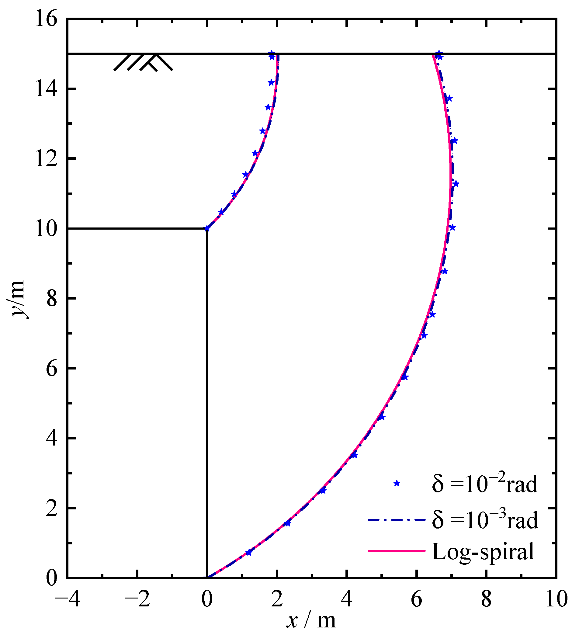
In the context of the plastic limit theorem, the analytical solution of the required support pressure is obtained based on the energy equilibrium equation. It is noted that the critical face pressure in Equation (35) depends on two dependent variables which control the geometry of the velocity field and a time variable that determines the distribution of acceleration. A random set of angles can determine a specific geometry of the failure mechanism based on which an upper-bound solution can be calculated. To calculate the least upper bound that is closest to the true solution, the enumeration method is adopted to search for the optimal solution. Before the parametric analysis, the accuracy and rationality of the proposed method are of necessity to be validated. The following parameters are inputted: C = 5   m , D = 10   m , c 1 = c 2 = 10   kPa , φ 1 = φ 2 = 10 , γ 1 = γ 2 = 18   kN / m 3 , σ s = 0 , k = 1.0 , and k h = 0 . Table 1 presents the required support pressure by the conventional log-spiral mechanism and discretized mechanism under homogeneous and isotropic soils, while Table 2 calculates the support pressure in heterogeneous and anisotropic soils for comparison. It is noted from Table 1 that the smaller discretized angle δ , the higher the accuracy of the solution, when δ = 0.001   rad , the maximum difference of the solutions between the discretized mechanism and log-spiral mechanism decreases to 0.12%, which is neglectable. Also, the failure mechanisms obtaining the optimal solution are illustrated in Figure 5 with different incremental δ values, it is shown that the discretized mechanism is nearly identical to the log-spiral mechanism when δ = 0.001   rad , and therefore, the incremental angle is set as 0.001 rad considering the accuracy and efficiency in the sequel.
The results in Table 2 are calculated based on the log-spiral mechanism and discretized mechanism, and the conventional linear variation in heterogeneity of soil strength with depth is considered. In the discretized mechanism, both the heterogeneity and anisotropy of the cohesion are considered; however, for φ and γ , only the heterogeneity is considered due to their little dependence on the direction. The log-spiral mechanism is incapable of considering the heterogeneity of φ because a variational φ will make it difficult to explicitly express the failure mechanism, which is also the reason why the discretization technique is necessarily used in this paper. The comparative results indicate that the difference in solutions resulting from failure mechanisms is small, and the consideration of the heterogeneity of the φ and γ leads to a stable tunnel face; however, such an enhancement effect on tunnel faces cannot be found from the cohesion because the reduction impact of anisotropy of c on the stability of tunnel faces is dominant. It is preliminarily speculated that the anisotropy of cohesion is an unfavorable factor to the face stability. This guess will be further investigated in the following parametric study.
In the presence of earthquakes, two methods are commonly used to represent the distribution of seismic acceleration induced by body waves including the pseudostatic method and the CPD. The pseudostatic method assumes a time- and position-independent distribution of seismic acceleration, which is convenient to apply to different situations but usually yields a conservative solution. The CPD remedies the deficiencies of the pseudostatic method by considering the spatiotemporal variation characteristic of accelerations. However, the zero-stress boundary condition is not satisfied. Letting the wave velocity be infinite, the CPD and MPD become the pseudostatic method. Therefore, based on the dynamic parameters ξ = 0.1 , k v / k h = 0.5 , k h = 0.1 , T = 0.2   s , and V s = 100   m / s , a comparison between the conventional pseudodynamic solution (f = 1) and the pseudostatic solution is made in Table 3. It is shown that the pseudostatic method always obtains the greatest solution because a peak ground acceleration is assumed to be uniformly distributed in the whole failure block. The support pressure obtained by the MPD is greater than that of Zhong and Yang [32] by the CPD and show good consistency with each other. In general, the correctness and accuracy of the proposed method are validated, and the detailed parametric study will be carried out in the following text.

5.2. Parametric Studies

This subsection aims to analyze the intrinsic influence of the heterogeneity and anisotropy of soil parameters on the required support pressure. Based on the previous description, the enumeration algorithm is adopted herein to search for the support pressure in the limit state, which is programmed and executed in a MATLAB environment. The following optimization procedure proceeds with basic input parameters: c 1 = 10   kPa , c 2 = 20   kPa , φ 1 = 10 ° , φ 2 = 20 ° , γ 1 = 16   kN / m 3 , γ 2 = 20   kN / m 3 , σ s = 10   kPa , k = 1.0 , C = 5   m , and D = 10   m .

5.2.1. Influence of Heterogeneity and Anisotropy

The heterogeneity of soil strength mainly reflects the variation in strength parameters with depth due to the sedimentation and consolidation, in the conventional analyses regarding the non-uniformity of soil strength, the assumption of the linear distribution of soil strength parameters is usually made, particularly for normally consolidated soils, while in this work, it is further extended to the other polynomial distributions including quadratic and cubic profiles.
The impact of heterogeneity of cohesion on the face stability is given in Figure 6a, where the cohesion from the coordinate y = C + D to y = 0 presents constant, linear, quadratic, and cubic increases. It can be seen that the constant profile of cohesion leads to the highest support pressure compared to the other three profiles. Interestingly, such an estimation via the constant profile is close to that of the linear profile. However, the quadratic and cubic variation in cohesion with depth obtains decreasing solutions with the increase in the exponent of the polynomial; such a case is caused by the fact that the convexity of quadratic and cubic distributions provides a higher resistance than that of the constant and linear profiles, as observed in the subgraph in Figure 6a. For the heterogeneity of friction angle, the same effect as cohesion is found in Figure 6b, because the increase in cohesion and friction angle offers greater shear strength to the soils. Notably, the impact of φ on the stability of tunnel faces is more significant than cohesion with a maximum reduction in the face pressure attaining up to 28%, as index α varies from 0 (constant profile) to 3 (cubic profile). In Figure 6c, the impact of unit weight on the face pressure presents a different trend from that of shear strength parameters. An increase in the exponent of the polynomial results in an unstable tunnel face, namely, a greater face pressure, which implies that γ is an unfavorable factor in the stability of the face.
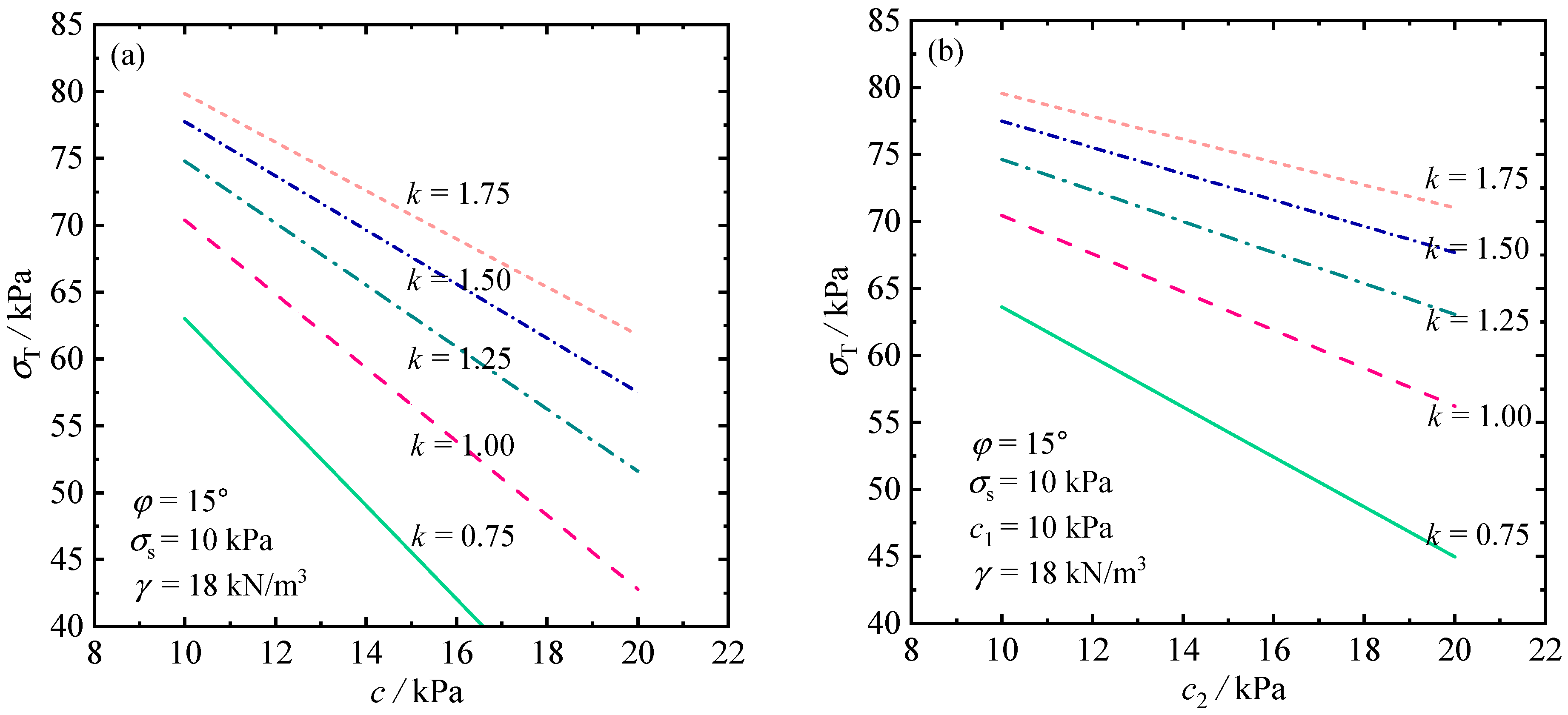
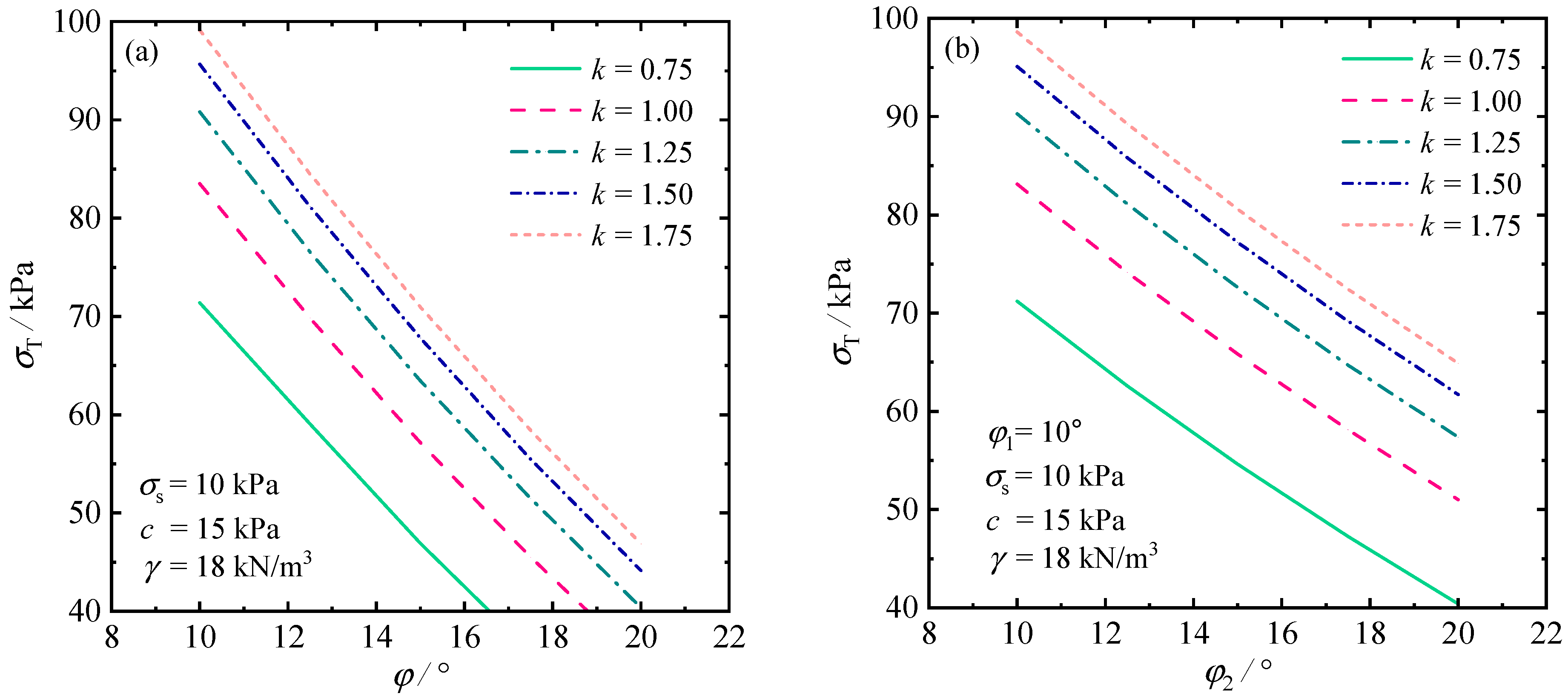
The cohesion of soils normally presents a distinct anisotropy with shearing direction. This feature is described by introducing an anisotropic coefficient k, whose value ranges from 0.75 to 2. The resistance preventing the tunnel face from collapsing is provided directly by shear forces along the slip surface. Based on the Mohr–Coulomb failure criterion, shear force relies on cohesion and friction angle. For a tunnel excavated in uniform soils with constant cohesion, the effect of cohesion on required support pressure is shown in Figure 7a, from which one can find that the stability of tunnel faces is improved by increasing soil cohesion. The geometry of the failure mechanism depends on the friction angle, which affects the required support pressure. As expected, a higher friction angle means better soil strength, which enables the tunnel face to maintain self-stability in a smaller support pressure, as illustrated in Figure 8a. Moreover, the reduction in required support pressure is 22.6% under k = 1.75 when cohesion is increased from 10 kPa to 20 kPa, while such a reduction is 52.7% when the friction angle varies from 10° to 20°, which indicates that the influence of friction angle on the required support pressure is more significant than that of cohesion. It is worth noting that the tunnel face becomes unstable as the anisotropy coefficient increase, at the same time, the improvement effect on the tunnel face by increasing the cohesion is gradually decreased. However, such a phenomenon is not found from the friction angle because the anisotropy only involves cohesion. The soil weight produces positive work in the limit failure state; therefore, the required support pressure is increased as the unit weight of soils is getting higher, as shown in Figure 9a. In the non-uniform soils, the required support pressure is plotted against different C 2 , φ 2 , and γ 2 (at the invert of tunnel face) and k values, as shown in Figure 7b, Figure 8b, and Figure 9b, with C 1 , φ 1 , and γ 1 kept at 10 kPa, 10°, and 16 kN/m3 at the crown of the tunnel face, respectively. An increase in required support pressure is observed when C 2 varies from 10 to 20 kPa. It is worthwhile noting that this decrease in the gradient is much lower than the uniform cohesion profile, as shown in Figure 7a. The same phenomenon can be found in the friction angle and unit weight of soils.
The possible failure region is also a major concern in practical engineering, especially for shallow tunnels whose collapse is more prone to protrude to the surface. Therefore, the critical failure mechanism for obtaining the optimal solution is directly plotted according to the coordinates of discretized points under different influential factors. Based on the linear profile and anisotropy coefficient k = 1.5, Figure 10 illustrates the influences of the heterogeneity of cohesion, friction angle, and unit weight on the critical failure mechanism, respectively. Generally, the friction angle has the greatest impact on the geometry of the failure mechanism, and the size of the failure area that extends to the surface obviously shrinks as the friction angle increases, because the failure mechanism is directly determined by the friction angle, as mentioned above. The effect of cohesion on the failure mechanism is slightly more obvious than that of unit weight.

5.2.2. Influence of the Earthquake

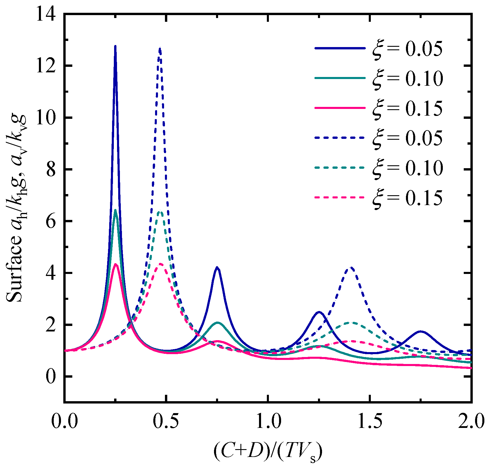
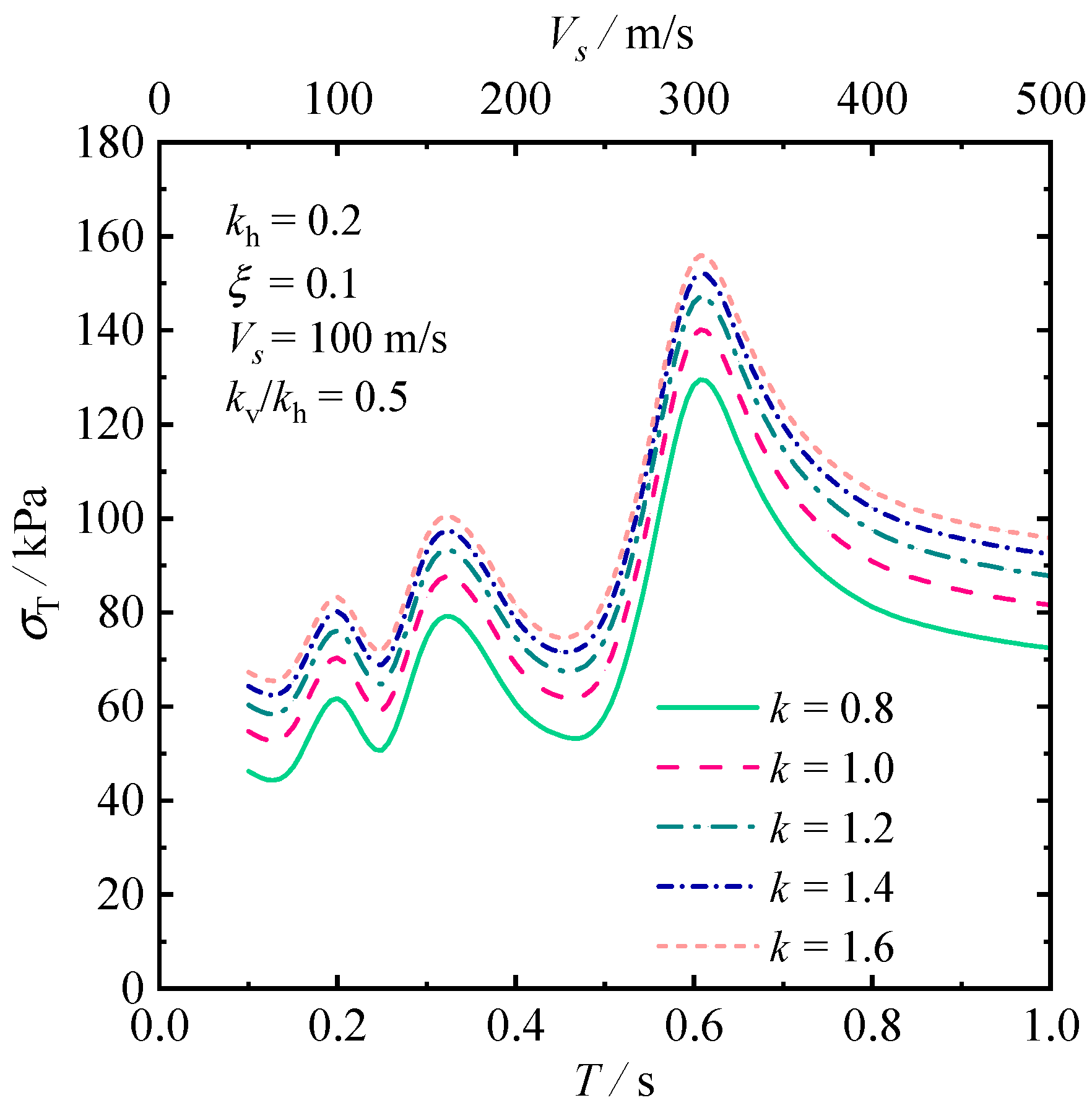
In the presence of an earthquake, the seismic stability of tunnel faces is more of a concern to engineers. The MPD used in this work is capable of considering the effect of resonance on the acceleration amplitude, as shown in Figure 11, where the solid lines represent the shear wave, and the dashed lines represent the primary waves. The amplitude at the surface is significantly increased when the ratio of C + D to the wavelength achieves the natural frequencies of soils. Considering the nonuniform soils in the linear profile, the double x-axis graph in Figure 12 presents the variation in required support pressure with the period and wave velocity, respectively, under different anisotropy coefficients. It is observed that the support pressure behaves in a fluctuating change with the period and wave velocity. The maximum/minimum of the required support pressure is obtained when the ratio of C + D to the wavelength reaches resonance points. As the period or wave velocity increases to infinity, the fluctuation disappears. This is because the ratio of C + D to the wavelength approach zero, and the amplitude amplification effect disappears.
The effect of seismic coefficients on face stability with respect to different anisotropy coefficients is investigated in Figure 13, from which one can observe that the influence of the horizontal seismic coefficient on face stability is greater than that of the vertical seismic coefficient. For instance, the required support pressure is decreased by about 15.2% when kh ranges from 0.1 to 0.2, while when kv varies from 0.1 to 0.2, the required support pressure decreases by about 2.3%. It is indicated that the effect of the vertical seismic acceleration is negligible compared with the horizontal seismic acceleration.
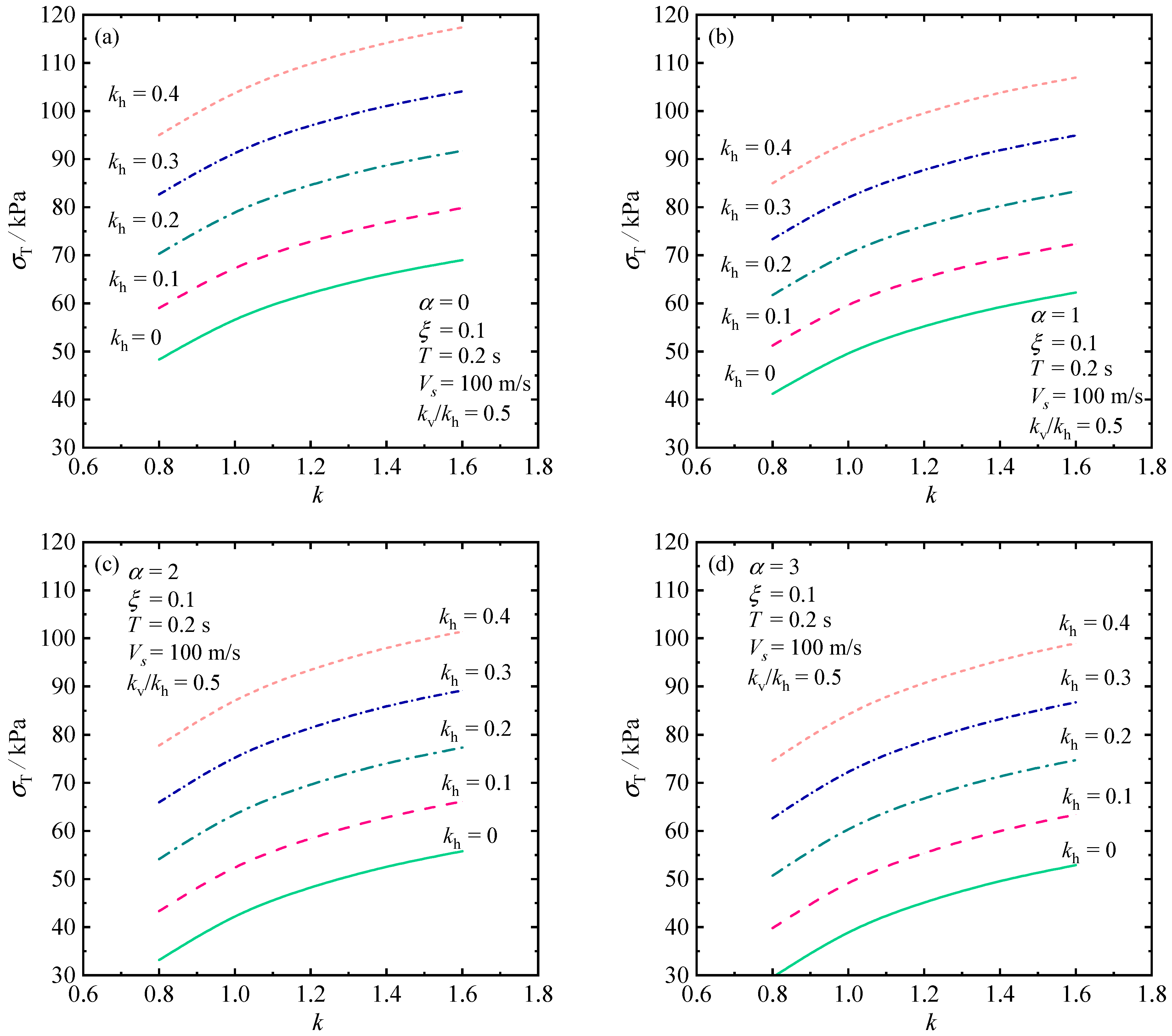
To find more insights into the effect of earthquakes on face stability in nonuniform and anisotropic soils, the required support pressure as a function of the anisotropy coefficient and horizontal seismic coefficient is plotted in Figure 14, where the subgraphs (a)–(d) represent the cases in constant, linear, quadratic, and cubic profiles, respectively. It is observed that the required support pressure presents a nonlinear tendency as the anisotropy coefficient increases, rather than the linear variation observed in previous parameters. The presence of earthquakes greatly influences the stability of the tunnel face, with the required support pressure increasing by more than twice from kh = 0 to kh = 0.3. In practical engineering, although the earthquake situation may rarely be encountered, once it happens, the property losses and casualties are huge. Therefore, the assessment of the seismic stability of tunnel faces is necessary from the perspective of risk reduction and safety assessment. Moreover, the influence of cover depth on the face stability is investigated in Figure 15, from which one can see that for the shield-driven tunnels with a diameter of 6 m, the resonance is more prone to happen, and the required support pressure significantly increases when the cover depth is small. The tunnel face gradually becomes stable with the cover depth increasing, and the corresponding support pressure rapidly decreases, even maintaining self-stability without support.

6. Conclusions

This work revisits the seismic stability problem of circular tunnels excavated in heterogeneous and anisotropic soils via a discretization technique in the context of the plastic limit theorem. The proposed procedure is made up of the following: (a) determination of the possible failure mechanism respecting the associative flow rule via a point-to-point method; (b) extension of the linear profile of soil strength to a universal polynomial distribution in heterogeneous and anisotropic soils; (c) assessment of the seismic stability of tunnel faces by the MPD.
A parametric study indicates that consideration of the nonlinear profiles of shear strength parameters with depth tends to attain a smaller prediction of required support pressure compared with the conventional linear and constant profiles, because such nonlinear profiles are convex and can provide more resistance to prevent the tunnel face from instability. However, the nonlinear profiles of unit weight will increase the external work rate and weaken the face stability. As for the impact of anisotropy of soils, it is found that for the most over-consolidated soils, namely, k < 1, the required support pressure is sensitive to the anisotropy coefficient, while for normally consolidated soil, the required support pressure increases steadily with the increase in the k value. The variation in friction angle with depth results in having a prominent impact on the geometry of the failure mechanism. In the presence of earthquakes, the effect of the horizontal seismic coefficient is much greater than the vertical seismic coefficient, which may be the reason why scholars tend to overlook vertical acceleration. Moreover, the resonance effect is an important factor that significantly affects face stability, especially for shallow-buried tunnels, in which the resonance effect is more prone to happen. In general, this work provides a new framework to evaluate the seismic stability in nonuniform and anisotropic soils, which has a guiding significance for practical engineering. In practical use, the analytical solution of this paper should be taken as a reference together with specific seismic data as well as with computational results of computer models of corresponding numerical solutions.
The main limitations of this study lie in the following two aspects: (1) this work analyzes the face stability based on the plain strain condition, and the solution obtained from the conventional two-dimensional analysis is safe in engineering but conservative. In practice, the collapse of the tunnel face usually presents an evident three-dimensional spatial feature, and therefore, it is necessary to conduct a three-dimensional analysis. (2) The earthquake effect is considered by the modified pseudodynamic method, which only involves the body waves and does not take the surface waves, such as Rayleigh waves and Love waves, into consideration. For far-field earthquakes, the damage effect of surface waves is more significant than body waves, and therefore, the surface wave should be considered in the analysis in future work.

Author Contributions

Writing—original draft preparation, writing—review and editing, visualization, supervision, software, validation, X.C.; formal analysis, investigation, resources, data curation, conceptualization, methodology, K.Z.; project administration, funding acquisition, W.W. All authors have read and agreed to the published version of the manuscript.

Funding

This work was supported by the Natural Science Foundation of the Higher Education Institutions of Jiangsu Province of China (20KJB560006), and Natural Science Foundation of the Higher Education Institutions of Jiangsu Province of China grant number (23KJB130001).

Institutional Review Board Statement

Not applicable.

Informed Consent Statement

Not applicable.

Data Availability Statement

The data that support the findings of this study are available from the corresponding author, upon reasonable request.

Acknowledgments

Not applicable.

Conflicts of Interest

The authors declare no conflict of interest.

References

  1. Zhou, Z.; Ling, T.; Huang, F.; Zhang, M. The Face Stability Analysis of Shield Tunnels Subjected to Seepage Based on the Variational Principle. Sustainability 2022, 14, 16538. [Google Scholar] [CrossRef]
  2. Jiang, B.; Ding, M.; Li, W.; Gu, S.; Ji, H. Investigation on Characteristics and Prevention of Rockburst in a Deep Hard and Soft Compound Stratum Tunnel Excavated Using TBM. Sustainability 2022, 14, 3190. [Google Scholar] [CrossRef]
  3. Perazzelli, P.; Leone, T.; Anagnostou, G. Tunnel face stability under seepage flow conditions. Tunn. Undergr. Space Technol. 2014, 43, 459–469. [Google Scholar] [CrossRef]
  4. Chen, R.P.; Tang, L.J.; Yin, X.S.; Chen, Y.M.; Bian, X.C. An improved 3d wedge-prism model for the face stability analysis of the shield tunnel in cohesionless soils. Acta Geotech. 2015, 10, 683–692. [Google Scholar] [CrossRef]
  5. Zhang, X.; Wang, M.N.; Wang, Z.L.; Li, J.W.; Tong, J.J.; Liu, D.G. A limit equilibrium model for the reinforced face stability analysis of a shallow tunnel in cohesive-frictional soils. Tunn. Undergr. Space Technol. 2020, 105, 103562. [Google Scholar] [CrossRef]
  6. Wu, L.; Liang, Z.; Chen, M.; Zhou, J. Experiments and Fluent–Engineering Discrete Element Method-Based Numerical Analysis 550of Block Motion in Underwater Rock-Plug Blasting. Appl. Sci. 2023, 13, 348. [Google Scholar] [CrossRef]
  7. Yi, C.; Senent, S.; Jimenez, R. Effect of advance drainage on tunnel face stability using limit analysis and numerical simulations. Tunn. Undergr. Space Technol. 2019, 93, 103105. [Google Scholar] [CrossRef]
  8. Li, C.; Wang, Z.; Liu, Q. Numerical Simulation of Mudstone Shield Tunnel Excavation with ABAQUS Seepage–Stress Coupling: A Case Study. Sustainability 2023, 15, 667. [Google Scholar] [CrossRef]
  9. Niu, Y.; Ren, T.; Zhou, Q.; Jiao, X.; Shi, J.; Xiang, K.; Tao, J.; Zhai, Q.; Satyanaga, A. Analysis of Excavation Parameters on Face Stability in Small Curvature Shield Tunnels. Sustainability 2023, 15, 6797. [Google Scholar] [CrossRef]
  10. Hou, C.; Zhong, J.; Yang, X. Three-dimensional stability assessments of a non-circular tunnel face reinforced by bolts under seepage flow conditions. Tunn. Undergr. Space Technol. 2023, 131, 104831. [Google Scholar] [CrossRef]
  11. Zhong, J.; Hou, C.; Yang, X. Three-dimensional face stability analysis of rock tunnels excavated in Hoek-Brown media with a novel multi-cone mechanism. Comput. Geotech. 2023, 154, 105158. [Google Scholar] [CrossRef]
  12. Zhong, J.; Zhao, S.; Wang, P.; Hou, C. Tunnel Face Stability Considering the Influence of Excess Slurry Pressure. Sustainability 2023, 15, 8230. [Google Scholar] [CrossRef]
  13. Hou, C.; Yang, X. Three-dimensional face stability of tunnels in unsaturated soils with nonlinear soil strength. Int. J. Geomech. 2021, 21, 06021006. [Google Scholar] [CrossRef]
  14. Li, Z.W.; Yang, X.L. Active earth pressure for soils with tension cracks under steady unsaturated flow conditions. Can. Geotech. J. 2018, 55, 1850–1859. [Google Scholar] [CrossRef]
  15. Li, Z.W.; Yang, X.L.; Li, T.Z. Static and seismic stability assessment of 3D slopes with cracks. Eng. Geol. 2020, 265, 105450. [Google Scholar] [CrossRef]
  16. Zhang, Z.L.; Yang, X.L. Pseudo-dynamic analysis of three-dimensional fissured slopes reinforced with piles. Int. J. Geomech. 2023, 23, 04022315. [Google Scholar] [CrossRef]
  17. Li, T.Z.; Gong, W.P.; Tang, H.M.; Zhang, L.M. A meshed kinematical approach for 3D slope stability analysis. Int. J. Numer. Anal. Methods. 2022, 46, 2913–2930. [Google Scholar] [CrossRef]
  18. Zhang, Z.L.; Zhu, J.Q.; Yang, X.L. Three-Dimensional Active Earth Pressures for Unsaturated Backfills with Cracks Considering Steady Seepage. Int. J. Geomech. 2023, 23, 04022270. [Google Scholar] [CrossRef]
  19. Leca, E.; Dormieux, L. Upper and lower bound solutions for the face stability of shallow circular tunnels in frictional material. Géotechnique 1990, 40, 581–606. [Google Scholar] [CrossRef] [Green Version]
  20. Mollon, G.; Dias, D.; Soubra, A.H. Face stability analysis of circular tunnels driven by a pressurized shield. J. Geotech. Geoenviron. 2009, 136, 215–229. [Google Scholar] [CrossRef] [Green Version]
  21. Subrin, D.; Wong, H. Tunnel face stability in frictional material: A new 3D failure mechanism. Comptes Rendus Mec. 2002, 330, 513–519. [Google Scholar] [CrossRef]
  22. Mollon, G.; Dias, D.; Soubra, A.H. Rotational failure mechanisms for the face stability analysis of tunnels driven by a pressurized shield. Int. J. Numer. Anal. Methods. 2011, 35, 1363–1388. [Google Scholar] [CrossRef] [Green Version]
  23. Chakraborty, D.; Kumar, J. Stability of a long unsupported circular tunnel in soils with seismic forces. Nat. Hazards. 2013, 68, 419–431. [Google Scholar] [CrossRef]
  24. Saada, Z.; Maghous, S.; Garnier, D. Pseudo-static analysis of tunnel face stability using the generalized hoek-brown strength criterion. Int. J. Numer. Anal. Methods. 2013, 37, 3194–3212. [Google Scholar] [CrossRef]
  25. Sahoo, J.P.; Kumar, J. Stability of a circular tunnel in presence of pseudostatic seismic body forces. Tunn. Undergr. Space Technol. 2014, 42, 264–276. [Google Scholar] [CrossRef]
  26. Pan, Q.J.; Dias, D. The effect of pore water pressure on tunnel face stability. Int. J. Numer. Anal. Methods. 2016, 40, 2123–2136. [Google Scholar] [CrossRef]
  27. Pan, Q.J.; Dias, D. Three dimensional face stability of a tunnel in weak rock masses subjected to seepage forces. Tunn. Undergr. Space Technol. 2018, 71, 555–566. [Google Scholar] [CrossRef]
  28. Gong, W.; Juang, C.H.; Wasowski, J. Geohazards and human settlements: Lessons learned from multiple relocation events in Badong, China–Engineering geologist’s perspective. Eng. Geol. 2021, 285, 106051. [Google Scholar] [CrossRef]
  29. Li, T.Z.; Pan, Q.; Dias, D. Active learning relevant vector machine for reliability analysis. Appl. Math. Model. 2021, 89, 381–399. [Google Scholar] [CrossRef]
  30. Chen, G.H.; Zou, J.F.; Chen, J.Q. Shallow tunnel face stability considering pore water pressure in non-homogeneous and anisotropic soils. Comput. Geotech. 2019, 116, 103205. [Google Scholar] [CrossRef]
  31. Qin, C.B.; Chian, S.C. Seismic bearing capacity of non-uniform soil slopes using discretization-based kinematic analysis considering rayleigh waves. Soil. Dyn. Earthq. Eng 2018, 109, 23–32. [Google Scholar] [CrossRef]
  32. Zhong, J.H.; Yang, X.L. Kinematic stability of tunnel face in non-uniform soils. KSCE J. Civ. Eng. 2019, 24, 670–681. [Google Scholar] [CrossRef]
  33. Zhong, J.H.; Yang, X.L. Kinematic analysis of the three-dimensional stability for tunnel faces by pseudodynamic approach. Comput. Geotech. 2020, 128, 103802. [Google Scholar] [CrossRef]
  34. Kramer, S.L. Geotechnical Earthquake Engineering; Pearson Education: Cranbury, NJ, USA, 1996. [Google Scholar]
  35. Bellezza, I. A new pseudo-dynamic approach for seismic active soil thrust. Geotech. Geol. Eng. 2014, 32, 561–576. [Google Scholar] [CrossRef]
  36. Casagrande, A.; Carillo, N. Shear failure of anisotropic materials. J. Boston Soc. Civ. Eng. 1944, 31, 122–135. [Google Scholar]
Figure 1. The failure mechanism of tunnel faces: (a) tunnel face, (b) angle relationship in anisotropy, (c) heterogeneity model, (d) pseudodynamic seismic wave, and (e) anisotropic Principle.
Sustainability 15 11083 g001
Figure 2. Diagrammatic sketch of the discretized failure mechanism. (a) generation of failure mechanism; (b) discretization element.
Sustainability 15 11083 g002
Figure 3. Calculation of the external work rate.
Sustainability 15 11083 g003
Figure 4. Flowchart of the calculation process.
Sustainability 15 11083 g004
Figure 5. Failure mechanisms generated under different incremental δ values.
Sustainability 15 11083 g005
Figure 6. Required support pressure varying with surcharge in isotropic soils: (a) for cohesion profile, (b) for friction angle profile, and (c) for unit weight profile.
Sustainability 15 11083 g006
Figure 7. Required support pressure against anisotropic coefficient: (a) for constant cohesion, and (b) linear cohesion profile.
Sustainability 15 11083 g007
Figure 8. Required support pressure against anisotropic coefficient: (a) for constant friction angle, and (b) for linear friction angle profile.
Sustainability 15 11083 g008
Figure 9. Required support pressure against anisotropic coefficient: (a) for constant unit weight, and (b) for linear unit weight profile.
Sustainability 15 11083 g009
Figure 10. Critical failure surfaces in heterogeneous and anisotropic soils with k = 1.5: (a) for non-uniform cohesion, (b) for non-uniform friction angle, and (c) for non-uniform unit weight.
Sustainability 15 11083 g010
Figure 11. Ratios of seismic acceleration amplitudes at the surface to the invert of tunnel faces.
Sustainability 15 11083 g011
Figure 12. Influence of period and wave velocity on required support pressure.
Sustainability 15 11083 g012
Figure 13. Required support pressure varies with seismic coefficients (a) for horizontal acceleration and (b) for vertical acceleration.
Sustainability 15 11083 g013
Figure 14. Required support pressure varies with horizontal seismic coefficient: (a) for constant profile, (b) for linear profile, (c) for quadratic profile, and (d) for cubic profile.
Sustainability 15 11083 g014
Figure 15. Influence of (C + D)/(VsT) on required support pressure with k = 1: (a) for constant profile, (b) for linear profile, (c) for quadratic profile and (d) for cubic profile.
Sustainability 15 11083 g015
Table 1. Required face pressure in homogeneous and isotropic soils (in kPa).
Discretized MechanismLog-Spiral Mechanism
φ δ = 0.01 rad δ = 0.001 rad
c = 5c = 10c = 15c = 5c = 10c = 15c = 5c = 10c = 15
5137.86121.01104.41136.39119.64103.12136.23119.49102.98
10109.8994.6679.57108.5693.4178.40108.4193.2778.27
1582.6768.8155.0081.5967.8054.0681.4767.6953.96
2059.6547.0034.4058.8046.2133.6758.7046.1233.58
2541.5130.6519.8040.9230.1919.4540.8630.1319.41
Table 2. Required face pressure in heterogeneous and anisotropic soils (in kPa).
C/DDiscretized Mechanism Log-Spiral Mechanism
Homogeneity and IsotropyHeterogeneity and AnisotropyHomogeneity and IsotropyHeterogeneity and Anisotropy
c / kPa φ / ° γ / kN m 3 c / kPa γ / kN m 3
0.2072.0478.9568.7569.5971.9478.8469.48
0.4086.8294.5183.0084.3186.6994.3884.18
0.6099.42107.7294.7797.1199.27107.5696.95
0.80109.47118.29103.89107.55109.30118.11107.37
1.00116.65126.03110.26115.29116.45125.83115.08
1.20120.69130.75113.68120.07120.48130.53119.84
Table 3. Comparison of required face pressure under earthquakes (in kPa).
φ / This Study Zhong and Yang [32]
Pseudostatic MethodResults by MPD Results by CPD
kh = 0.1kh = 0.3kh = 0.1kh = 0.3kh = 0.1kh = 0.3
5140.34194.84130.72160.02130.62154.19
10108.79144.01106.13134.54103.94124.48
1580.51107.4580.22107.4977.1295.72
2056.5477.8257.0180.7153.9769.31
2538.3555.3239.1058.9136.2548.48
Disclaimer/Publisher’s Note: The statements, opinions and data contained in all publications are solely those of the individual author(s) and contributor(s) and not of MDPI and/or the editor(s). MDPI and/or the editor(s) disclaim responsibility for any injury to people or property resulting from any ideas, methods, instructions or products referred to in the content.