Article

Numerical Simulation of Hydrogen Diffusion in Cement Sheath of Wells Used for Underground Hydrogen Storage

Department of Petroleum Engineering, University of Louisiana at Lafayette, Lafayette, LA 70504, USA
*
Author to whom correspondence should be addressed.
Sustainability 2023, 15(14), 10844; https://doi.org/10.3390/su151410844
Submission received: 29 April 2023 / Revised: 7 July 2023 / Accepted: 10 July 2023 / Published: 11 July 2023
(This article belongs to the Special Issue Advanced Clean Energy Systems)

Abstract

:
The negative environmental impact of carbon emissions from fossil fuels has promoted hydrogen utilization and storage in underground structures. Hydrogen leakage from storage structures through wells is a major concern due to the small hydrogen molecules that diffuse fast in the porous well cement sheath. The second-order parabolic partial differential equation describing the hydrogen diffusion in well cement was solved numerically using the finite difference method (FDM). The numerical model was verified with an analytical solution for an ideal case where the matrix and fluid have invariant properties. Sensitivity analyses with the model revealed several possibilities. Based on simulation studies and underlying assumptions such as non-dissolvable hydrogen gas in water present in the cement pore spaces, constant hydrogen diffusion coefficient, cement properties such as porosity and saturation, etc., hydrogen should take about 7.5 days to fully penetrate a 35 cm cement sheath under expected well conditions. The relatively short duration for hydrogen breakthrough in the cement sheath is mainly due to the small molecule size and high hydrogen diffusivity. If the hydrogen reaches a vertical channel behind the casing, a hydrogen leak from the well is soon expected. Also, the simulation result reveals that hydrogen migration along the axial direction of the cement column from a storage reservoir to the top of a 50 m caprock is likely to occur in 500 years. Hydrogen diffusion into cement sheaths increases with increased cement porosity and diffusion coefficient and decreases with water saturation (and increases with hydrogen saturation). Hence, cement with a low water-to-cement ratio to reduce water content and low cement porosity is desirable for completing hydrogen storage wells.

1. Introduction

Carbon emissions from fossil fuels causing global warming have grown exponentially since the 19th century. As a result, energy companies strive to reduce their carbon footprint by transitioning to large-scale deployment of renewable energy. Although renewables such as solar and wind are intermittent in supply, hydrogen is the most abundant element and a primary sustainable renewable energy source.
The low energy density of hydrogen implies that it requires more volumetric storage capacity than natural gas to produce the same energy [1,2]. Consequently, large-scale subsurface porous media, such as salt caverns, aquifers, and depleted oil and gas reservoirs, are more practical options for underground hydrogen storage (UHS) [3].
Depleted oil and gas reservoirs are the most sorted candidates for UHS; they have rich databases to support Underground Storage (UGS) site activities and have been studied extensively by geoscientists and reservoir engineers. In addition, studies show that the geological trap mechanisms of most depleted oil and gas reservoirs demonstrate structural integrity and safety, as they have kept their hydrocarbons for millions of years without leaks. Finally, the economics of injecting and producing hydrogen from depleted oil and gas reservoirs are relatively cost-effective compared to other storage options, as there are existing infrastructures such as wells, pipelines, etc. [4,5].
Hydrogen stored in the subsurface can instigate stress changes on the caprock and reservoir rocks during cyclical injection and production. In addition, the reservoir’s pre-existing fluids and subsurface minerals may also react with hydrogen, consequently resulting in microbial growth, which could affect the fluid dynamics [2]. Containment in UHS may also leak away through the caprock, specific faults or fractures, and older leaky wells with outdated designs.
According to the Subsurface Hydrogen Assessment, Storage and Technology Acceleration (SHASTA)/DOE 2022 report, several notable well-leakage incidents have occurred at UGS facilities over the past 20 years. These incidents are often caused by well design, integrity, and safety issues [6,7,8]. Existing wells used for injecting and producing stored hydrogen at UHS sites must have good structural integrity, i.e., the wells must withstand various loads and extreme weather conditions throughout their service lives and guard against potential leaks and corrosion [9,10]. Otherwise, ineffective storage, economic losses, risks to human health, or environmental hazards are inevitable.
The central components of well constructions are steel, polymer elastomers, and cement. Usually, when one or more of these components fail, it leads to containment loss from the UHS. Several researchers have studied the interactions between stored hydrogen and well construction components—for instance, experimental research on hydrogen embrittlement in low-carbon steels resulted in premature steel failure and cracking. Additionally, researchers are looking into new mitigation strategies for developing new steels resistant to hydrogen embrittlement [11,12,13]. For instance, Ramjaun et al. [14] designed a novel steel HT10 that exhibits excellent hydrogen trapping capacity while maintaining mechanical properties comparable to F22-grade steel. Microbial corrosion is another mechanism that can jeopardize well integrity and result in UHS leaks, as reported in the research works of Ugarte and Saeed [15].
Elastomer degradation by hydrogen permeation can affect the well’s structural integrity. According to research, rapid gas decompression, chemical degradation and temperature, extrusion and nibbling, wear, compression set, and spiral failure are the most common failure mechanisms in elastomers operating in downhole environments [16,17]. Simmons et al. [18,19] summarized recent experimental efforts to help understand polymeric materials’ compatibility in the hydrogen infrastructure. They developed a knowledge base of elastomer and polymer materials’ hydrogen compatibility by developing test procedures that will make it possible to comprehend how materials interact in infrastructure better, which will direct future research and development initiatives. Parallel to experimental work, computational studies have made significant strides, increasing our ability to predict how well elastomer materials will perform in high-pressure gaseous hydrogen [20].
However, there are few works on hydrogen reactivity and diffusion through cement, unlike the extensive literature on well integrity and cement strength in wells of depleted oil and gas reservoirs used for underground CO2 sequestration. Hydrogen is the smallest molecule and has a high diffusivity; as a result, it will escape from the reservoir through fractures, vugs, and fissures in the cement sheath, leading to uncontrolled release into neighboring permeable formations or on the surface [21,22]. Hydrogen leakage can also occur due to cement shrinkage between the formation and well casing caused by salt rock creeping [23,24,25,26].
The integrity of the cement sheath seal is critical for the safe implementation of UHS [21,27]. Cracolici et al. [2] and Iorio et al. [28] experimentally investigated the cement compatibility in UHS of depleted oil and gas reservoirs. The cement’s compressive strength, permeability, porosity, saturation, and chemical properties were analyzed pre- and post-hydrogen exposure. Jacquemet et al. [29] evaluated the geochemical impact of hydrogen and natural gas reactivity in an aquifer with well cement. This study aids in determining the feasibility and potential risks of hydrogen co-storage in the aquifer. Sercombe et al. [30] conducted an experimental study of gas diffusion in cement paste, where they showed that gas diffusion decreases with increasing relative humidity. Teodoriu et al. [31] studied the effects of salt concentration on class G cement for wells used in underground gas storage sites. The study analyzed the thickening time, compressive strength, elastic modulus, and set cement permeability of class G cement at different salt concentrations. The researchers were curious about how salts affected the performance and integrity of cement used in underground gas storage wells by varying the salt concentration.
The numerical simulation of hydrogen migration into cement sheaths is an essential tool for researchers and engineers to understand the complex processes involved in the degradation of oil and gas well cementing in UHS. It provides a powerful approach to modeling the physical and chemical phenomena involved in hydrogen migration and predicting the behavior of cement sheaths under different scenarios. Ghaedi et al. [32] used a series of one- and three-dimensional numerical models to investigate hydrogen diffusion through the caprock during geological storage. In addition, a semi-analytical solution was proposed to predict the cumulative hydrogen loss over time.
Unfortunately, there are no or limited numerical simulations of hydrogen diffusion through the cement sheathes of oil and gas wells used in UHS. Hence, the primary goal of this study was to provide numerical simulations of hydrogen diffusion through the cement sheath of a well used in hydrogen storage by simulating Fick’s second law of diffusion for fixed-concentration boundary conditions. In addition, a modified effective diffusion coefficient of hydrogen was introduced into Fick’s second law of diffusion to account for the presence of other substances in the cement pores. Simulation models were then verified using an analytical model. Sensitivity analysis was performed to understand better the complex processes involved in the degradation of the cement sheath with invariant matrix and fluid properties by hydrogen migration. Finally, this work simulated the hydrogen migration time along the axial direction of a cement column with varying matrix and fluid properties above the hydrogen storage zone.

2. Mathematical Model

Fick’s second law of diffusion is a generalization of Fick’s first law of diffusion, which states that the flux of a substance across a plane is proportional to the concentration gradient in that plane [33,34,35,36,37].
Fick’s second law of diffusion is a second-order parabolic partial differential equation describing a substance’s diffusion in a medium. It considers the substance’s time-dependent (non-steady state) diffusion in the medium. Based on this study, Fick’s second law of diffusion will describe the diffusion of hydrogen (substance) through a cement sheath (medium).
The solution to Fick’s second law of diffusion depends on the boundary and initial conditions. For fixed-concentration boundary conditions, the concentration of hydrogen is fixed at one end of a one-dimensional medium of length L, and there is initially no hydrogen in the medium.
Fick’s second law of diffusion is given by:
C x , t t = D e f f 2 C x , t x 2 ,
D e f f = D o   ( 1 S w ) Ø ,
Initial Condition:
C x , 0 = 0               x 0 ,
Boundary Conditions:
C 0 , t = C 0               t 0 ,
C x , t x   x = L = 0               t 0 ,
where C(x, t) is the concentration of the substance (hydrogen), t is time, x or L is the distance (cement thickness), S w   is the saturation of water in cement pores, ( 1 S w )   is the saturation of gas (hydrogen) in the cement pore, Ø is the porosity of the cement sheath, and D e f f   is the effective diffusion coefficient of hydrogen in the presence of other substances in the cement pores, while D o is the absolute diffusion coefficient of hydrogen in the absence of other substances in the cement pores. The diffusion coefficient will differ depending on subsurface variables such as concentration, temperature, and pressure [35].
Equation (1), subject to Neumann boundary conditions, can be solved analytically using Laplace transformations [38,39,40]. The analytical solution is presented below:
C x , t = C 0 n = 1 1 n 1 e r f c 2 n L x 2 D e f f t + e r f c 2 n 1 L + x 2 D e f f t .
The series converges fast, even at n ≤ 10.
Application of this solution is limited to homogeneous systems where both the porous matrix and the fluid are invariant in space. But in reality, matrix and fluid properties can vary spatially. For example, the porosity of well cement varies with depth, and the water saturation in the pore space also changes; in such conditions, a numerical model is highly desirable. The Finite Difference Method (FDM) was used to solve the equations numerically, and solutions were implemented with Python. The numerical formulation with second-order accurate approximation is shown in Appendix A. Three assumptions made in the numerical model are: (1) hydrogen is non-dissolvable in the water present in cement pores; (2) the diffusion coefficient of hydrogen remains constant in the UHS; and (3) the cement properties, such as porosity and saturation, could be constant or variable depending on the problem setup.

3. Model Validation

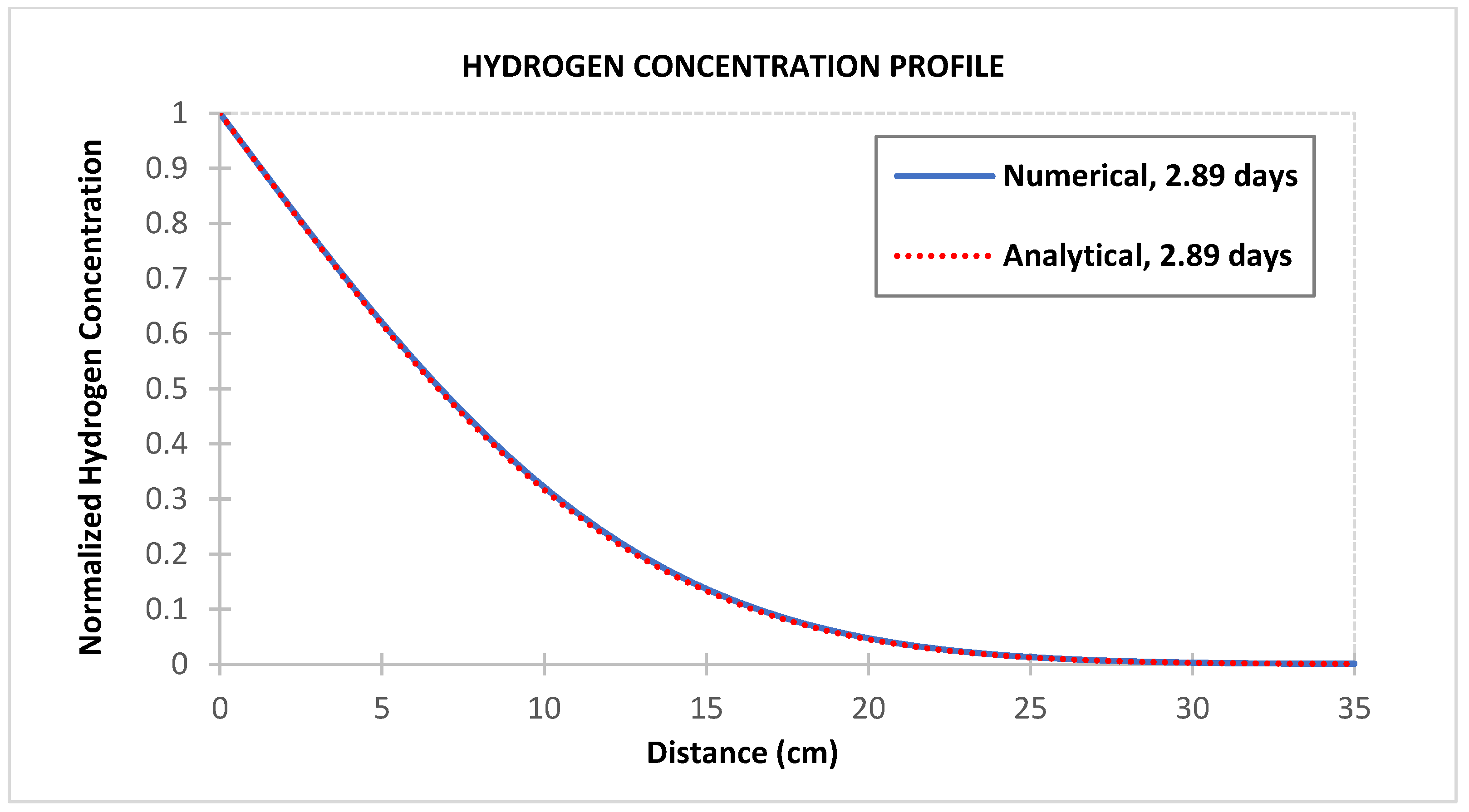
This section aims to investigate the correctness of the numerical model. We verify the numerical model presented in Appendix A with the analytical solution given by Equation (6). Table 1 presents input data to evaluate the hydrogen diffusion into the cement sheath of a well in a UHS site. The data were obtained from literature on well completion and SHASTA/DOE 2022 report.
Figure 1 compares the numerical results and the analytical solution after 2.89 days of hydrogen diffusion, demonstrating a good match between the two solutions. The solid blue curve represents the numerical solutions, while the red dotted curve represents the analytical solution. However, one challenge with the study is the absence of experimental studies, such as Scanning Electron Microscope/Energy Dispersive Spectroscopy (SEM-EDS) mapping and SEM-EDS point analysis for investigating the depth of hydrogen penetration in class G or H well cement under UHS conditions for further validation of the numerical model.

4. Numerical Experiments and Analysis of Results

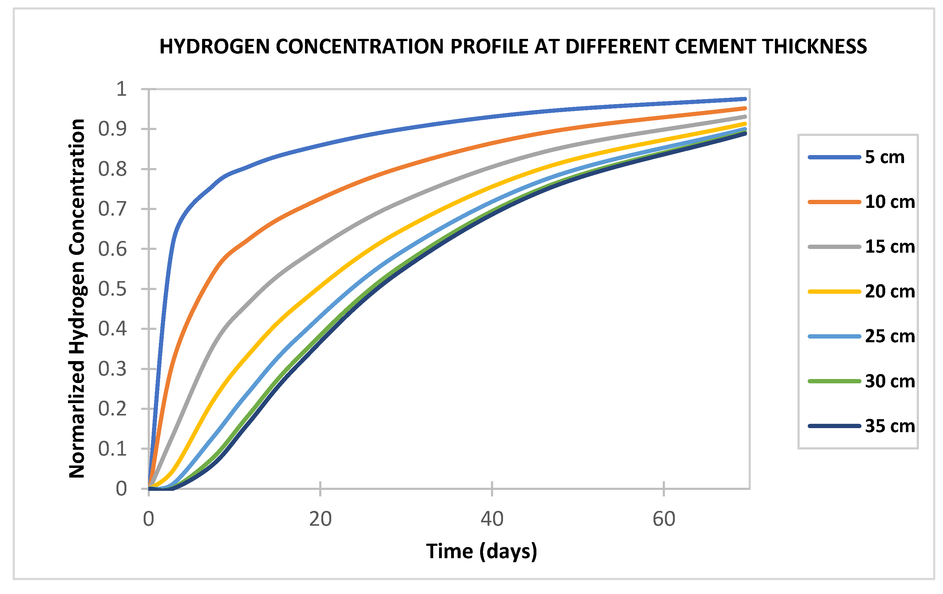
While the absence of experimental data may limit the direct validation of our numerical studies, we employed alternative approaches, such as sensitivity analysis. Sensitivity analyses were conducted to account for uncertainties in some parameter values presented in Table 1, such as coefficient of diffusion in the cement, cement porosity, gas saturation, and cement thickness.
In Figure 2, Figure 3 and Figure 4, simulation time ranging from 0.12 days to 69.44 days was run to expose the cement sheath to hydrogen diffusion until a breakthrough occurred. Hydrogen took about 7.5 days to penetrate the cement sheath fully. The minimum time for full penetration is when the hydrogen concentration at the end of the cement thickness reaches 10% of the initial normalized hydrogen concentration. Figure 2, Figure 3 and Figure 4 also show that it will take about 69 days for 90% of the initial hydrogen concentration to penetrate the cement sheath fully.
The relatively short duration for hydrogen breakthrough in the cement sheath is mainly due to the small molecule size and high hydrogen diffusivity. Therefore, the well cement integrity is paramount to ensure any successful UHS project.
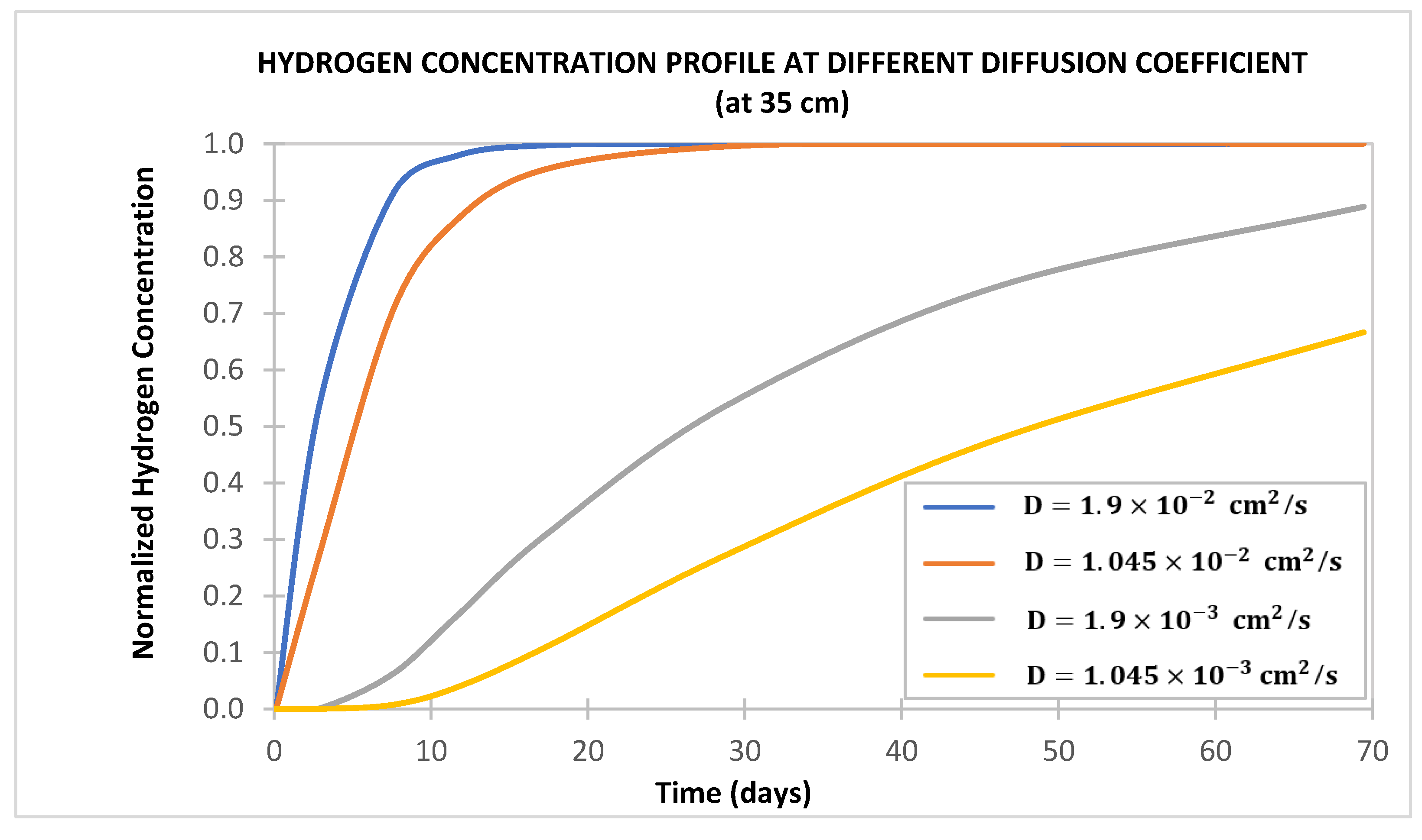
Figure 5 shows the sensitivity of the coefficient of diffusion of hydrogen. A hydrogen diffusion coefficient ranging from 0.019 cm2/s to 0.001945 cm2/s was selected to account for uncertainties in the actual hydrogen diffusion coefficient in cement used in UHS. Based on the SHASTA/DOE 2022 report [6], the diffusion coefficient decreased with curing time and increased with water–cement ratio. For example, for a water–cement ratio of 0.5, the diffusion coefficient was 0.019 cm2/s after 28 days of curing. We observed that an increase in the hydrogen diffusion coefficient would cause a corresponding increase in the hydrogen diffusion rate in the cement sheath. Conversely, decreasing the diffusion coefficient will result in a slower diffusion rate. In Figure 5, when the diffusion coefficient is in the magnitude of 10 2   cm 2 / s , hydrogen will fully penetrate the cement sheath within one to two days, but when the diffusion coefficient is in the magnitude of 10 3   cm 2 / s it takes a few months for hydrogen will fully penetrate the cement sheath. It is important to note that the diffusion coefficient could differ depending on subsurface variables such as concentration, temperature, and pressure.
Figure 6 shows the sensitivity of hydrogen saturation on the cement sheath. The result shows that when hydrogen is exposed to the cement sheath for a given period, the hydrogen diffusion rate in the cement sheath is higher when the water saturation in the cement pores is lower (higher hydrogen saturation) and vice versa. Figure 6 also shows that when the water saturation in the cement pore is 40% (i.e., 60% hydrogen saturation), the normalized hydrogen concentration in the fully penetrated cement sheath is 0.6. Conversely, when the water saturation in the cement pore is 90% (i.e., 10% hydrogen saturation), the normalized hydrogen concentration in the penetrated cement sheath is about 0.02.
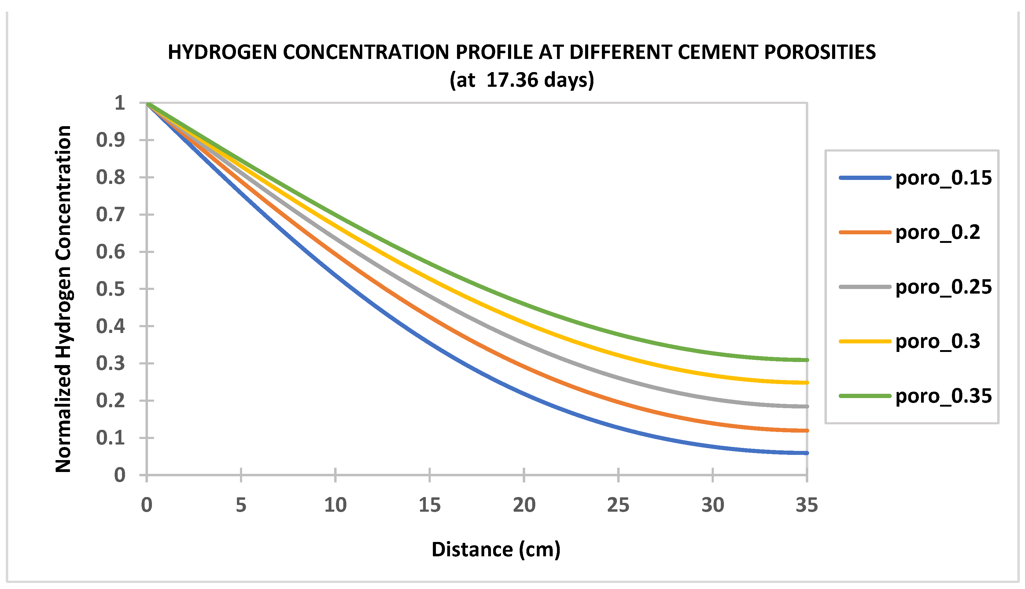
Figure 7 shows the sensitivity of the cement sheath porosity. When hydrogen is exposed to the cement sheath for a given period, the hydrogen concentration in the penetrated cement sheath increases with increased cement sheath porosities. Hence, cement with a low water-to-cement ratio, high compressive strength, and low cement porosity is desirable for wells used in UHS.
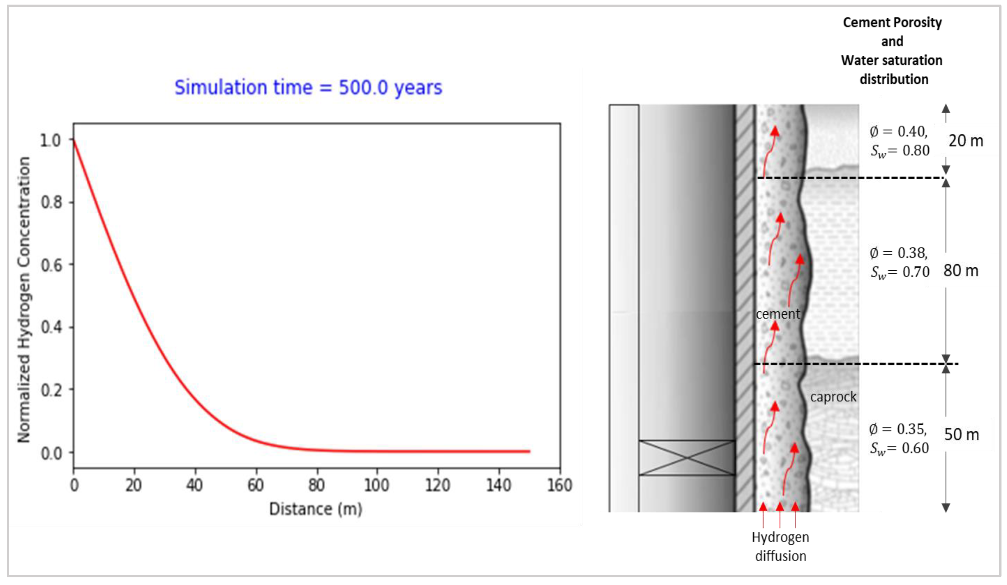
One advantage of the numerical simulation approach to hydrogen diffusion through the cement sheath over the analytical solution is the ability to simulate varying properties of cement, such as distributed porosity and water saturation in the pore spaces. For example, when investigating the time taken for hydrogen migration in the axial direction of the cement column above the storage zone (50 m of cement along the caprock thickness and 100 m above the caprock), if the cement column’s pore spaces have a varied distribution of cement porosities and water saturations and no crack on the cement sheath, as shown in Figure 8 below, then the time taken to penetrate the 50 m cement column across the caprock is estimated to be about 500 years.

5. Conclusions

In this study, the second-order parabolic partial differential equation describing hydrogen diffusion in the cement sheathes of wells used in UHS was solved numerically using the finite difference method (FDM) and implemented with Python. The numerical solution was verified with an analytical solution for an ideal case where matrix and fluid have invariant properties.
The significance of the numerical simulation approach over the analytical method is the ability to simulate hydrogen diffusion in cement with varying properties, such as geometry, distributed porosity, and water saturation in the pore space. This numerical approach will prove useful in expanding our understanding of how wells used for UHS can best be selected, monitored, and managed.
This study is limited by the absence of experimental studies, such as Scanning Electron Microscope/Energy Dispersive Spectroscopy (SEM-EDS ) mapping and SEM-EDS point analysis, for investigating the depth of hydrogen penetration in class G or H well cement under UHS conditions and as a result the numerical solution was not validated experimentally.
The following conclusions are drawn based on the sensitivity analysis conducted in this study:
  • Hydrogen should take about 7.5 days to fully penetrate a 35 cm cement sheath under the condition in Table 1. The relatively short duration for hydrogen breakthrough in the cement sheath is mainly due to the small molecule size and high hydrogen diffusivity. If the hydrogen reaches a vertical channel behind the casing, a hydrogen leak from the well is soon expected. Therefore, the well cement integrity is paramount to ensuring any successful UHS project.
  • Hydrogen diffusion into cement sheaths increases with increased cement porosity and diffusion coefficient and decreases with water saturation (increases with hydrogen saturation). Hence, cement with a low water-to-cement ratio to reduce water content and low cement porosity is desirable for wells used in UHS.
  • The simulation result implies that the time taken for hydrogen migration along the axial direction of a 50m cement column across the caprock and above the storage zone is estimated to be about 500 years. Hence, provided the cement sheath is crack-free, hydrogen leaks to the surrounding formations may likely happen along the traverse direction of the cement sheath during the operating life of the UHS sites.

Author Contributions

Conceptualization, A.D. and B.G.; methodology, A.D. and B.G.; numerical modelling, A.D. and Y.F.; validation, A.D., Y.F. and B.G.; investigation, A.D.; resources, A.D. and B.G.; writing—original draft preparation, A.D.; writing—review and editing, A.D., Y.F. and B.G.; visualization, A.D. and B.G.; supervision, F.Y and B.G. All authors have read and agreed to the published version of the manuscript.

Funding

This research received no external funding.

Institutional Review Board Statement

Not applicable.

Informed Consent Statement

Not applicable.

Data Availability Statement

Not applicable.

Acknowledgments

I thank Boyun Guo and Yin Feng for their invaluable guidance and support throughout this publication.

Conflicts of Interest

The authors declare no conflict of interest.

Appendix A

The Implicit Finite Difference formulation for Fick’s second law of diffusion with fixed concentration boundary conditions is presented below:
Discretizing Equations (1) and (5) using the Backward Euler Method.
From Equation (1)
C i + 1 , n   C i , n   Δ t   = D e f f   C i + 1 , n + 1   2 C i + 1 , n   + C i + 1 , n 1   Δ x 2         ,
where
D e f f = D o   ( 1 S w ) Ø ,
α = D o   ( 1 S w i ) Ø i   Δ t Δ x 2     ,
C i , n   = α     C i + 1 , n + 1   2 C i + 1 , n   + C i + 1 , n 1   + C i + 1 , n ,
C i , n   = ( 1 + 2 α ) C i + 1 , n       α C i + 1 , n + 1   α C i + 1 , n 1 ,
n = 1,
C i , 1   = ( 1 + 2 α ) C i + 1 , 1       α C i + 1 , 2   α C i + 1 , 0       ,
n = 2,
C i , 2   = ( 1 + 2 α ) C i + 1 , 2       α C i + 1 , 3   α C i + 1 , 1   ,
n = m,
                      C i , m   = ( 1 + 2 α ) C i + 1 , m       α C i + 1 , m + 1   α C i + 1 , m 1     ,
At the boundaries
C i + 1 , 0   = C 0   ,
From Equation (5)
d C               d x   i + 1 , m   = C i + 1 , m + 1   C i + 1 , m 1   2 Δ x   = 0 ,
C i + 1 , m + 1   = C i + 1 , m 1   ,
Vectorially, the discretized equation can be expressed as
1 + 2 α α       α 1 + 2 α α                 α 1 + 2 α α       2 α 1 + 2 α     . C i + 1 , 1 C i + 1 , 2 C i + 1 , m 2 C i + 1 , m 1   =   C i , 1 + α C 0   C i , 2 C i , m 2 C i , m 1
The resulting second-order finite difference scheme is of second-order accurate approximation. The error is proportional to the grid size squared, Δ x 2 .
The implicit FDM are unconditionally stable, converging for all Δx and Δt. Also, the above algorithm for Fick’s second law of diffusion is implemented in Python.

References

  1. Heinemann, N.; Alcalde, J.; Miocic, J.M.; Hangx, S.J.; Kallmeyer, J.; Ostertag-Henning, C.; Rudloff, A. Enabling large-scale hydrogen storage in porous media–the scientific challenges. Energy Environ. Sci. 2021, 14, 853–864. [Google Scholar] [CrossRef]
  2. Cracolici, F.; Iorio, V.S.; Parrozza, F.; Sabatino, L.M.F.; Previde Massara, E.; Consonni, A.; Poloni, R. Experimental Investigation of Cement Compatibility in Underground Hydrogen Storage in Depleted Reservoir. In Proceedings of the International Petroleum Technology Conference, Bangkok, Thailand, 1–3 March 2023. [Google Scholar]
  3. Lord, A.S.; Kobos, P.H.; Borns, D.J. Geologic Storage of Hydrogen: Scaling up to meet city transportation demands. Int. J. Hydrog. Energy 2014, 39, 15570–15582. [Google Scholar] [CrossRef] [Green Version]
  4. Agartan, E.; Gaddipati, M.; Yip, Y.; Savage, B.; Ozgen, C. CO2 storage in depleted oil and gas fields in the Gulf of Mexico. Int. J. Greenh. Gas Control 2018, 72, 38–48. [Google Scholar] [CrossRef]
  5. Michanowicz, D.R.; Buonocore, J.J.; Rowland, S.T.; Konschnik, K.E.; Goho, S.A.; Bernstein, A.S. A national assessment of underground natural gas storage: Identifying wells with designs likely vulnerable to a single-point-of-failure. Environ. Res. Lett. 2017, 12, 064004. [Google Scholar] [CrossRef]
  6. Goodman, H.A.; Kutchko, B.; Lackey, G.; Gulliver, D.; Strazisar, B.R.; Tinker, K.A.; Wright, R.; Haeri, F.; Huerta, N.; Baek, S. Subsurface Hydrogen and Natural Gas Storage: State of Knowledge and Research Recommendations Report; DOE/NETL-2022/3236; U.S. Department of Energy: Washington, DC, USA, 2022. [Google Scholar]
  7. Boersheim, E.C.; Reitenbach, V.; Albrecht, D.; Pudlo, D.; Ganzer, L. Experimental investigation of integrity issues of UGS containing hydrogen. In Proceedings of the SPE Europe Featured at 81st EAGE Conference and Exhibition, London, UK, 3–6 June 2019. [Google Scholar]
  8. Yang, Z.; Zhang, X.; Deng, D. Underground gas storage injection-production well completion process. Well Test. 2008, 2, 63–68. [Google Scholar]
  9. Bai, M.; Song, K.; Sun, Y.; He, M.; Li, Y.; Sun, J. An overview of Hydrogen underground storage technology and prospects in China. J. Pet. Sci. Eng. 2014, 124, 132–136. [Google Scholar] [CrossRef]
  10. Zhao, K. Injection Wells. The Formation Underground Gas Storage in the Process of the Usability Research. Ph.D. Thesis, Chinese Academy of Sciences, Beijing, China, 2009. [Google Scholar]
  11. Barrera, O.; Bombac, D.; Chen, Y.; Daff, T.D.; Galindo-Nava, E.; Gong, P.; Sweeney, F. Understanding, and mitigating hydrogen embrittlement of steels: A review of experimental, modeling and design progress from atomistic to continuum. J. Mater. Sci. 2018, 53, 6251–6290. [Google Scholar] [CrossRef] [Green Version]
  12. Djukic, M.B.; Zeravcic, V.S.; Bakic, G.; Sedmak, A.; Rajicic, B. Hydrogen embrittlement of low carbon structural steel. Procedia Mater. Sci. 2014, 3, 1167–1172. [Google Scholar] [CrossRef] [Green Version]
  13. Findley, K.O.; Lawrence, S.K.; O’Brien, M.K. Engineering challenges associated with hydrogen embrittlement in steels. In Encyclopedia of Materials: Metals and Alloys; Elsevier: Amsterdam, The Netherlands, 2022; pp. 235–249. [Google Scholar]
  14. Ramjaun, T.I.; Ooi, S.W.; Morana, R.; Bhadeshia, H.K.D.H. Designing steel to resist hydrogen embrittlement: Part 1—Trapping capacity. Mater. Sci. Technol. 2018, 34, 1737–1746. [Google Scholar] [CrossRef]
  15. Ugarte, E.R.; Salehi, S. A review on well integrity issues for underground hydrogen storage. J. Energy Resour. Technol. 2022, 144, 042001. [Google Scholar] [CrossRef]
  16. Brownell, M.; Frischknecht, A.L.; Wilson, M.A. Subdiffusive high-pressure hydrogen gas dynamics in elastomers. Macromolecules 2022, 55, 3788–3800. [Google Scholar] [CrossRef]
  17. Patel, H.; Salehi, S.; Ahmed, R.; Teodoriu, C. Review of elastomer seal assemblies in oil & gas wells: Performance evaluation, failure mechanisms, and gaps in industry standards. J. Pet. Sci. Eng. 2019, 179, 1046–1062. [Google Scholar]
  18. Simmons, K.L.; Kuang, W.; Burton, S.D.; Arey, B.W.; Shin, Y.; Menon, N.C.; Smith, D.B. H-Mat hydrogen compatibility of polymers and elastomers. Int. J. Hydrog. Energy 2021, 46, 12300–12310. [Google Scholar] [CrossRef]
  19. Simmons, K.; Bhamidipaty, K.; Menon, N.; Smith, B.; Naskar, A.; Veenstra, M. Compatibility of Polymeric Materials Used in the Hydrogen Infrastructure; DOE Annual Merit Review; Pacific Northwest National Laboratory: Richland, WA, USA, 2017. [Google Scholar]
  20. Kulkarni, S.S.; Choi, K.S.; Kuang, W.; Menon, N.; Mills, B.; Soulami, A.; Simmons, K. Damage evolution in polymer due to exposure to high-pressure hydrogen gas. Int. J. Hydrog. Energy 2021, 46, 19001–19022. [Google Scholar] [CrossRef]
  21. Arbad, N.; Teodoriu, C. A review of recent research on contamination of oil well Cement with oil-based drilling fluid and the need for new and accurate correlations. ChemEngineering 2020, 4, 28. [Google Scholar] [CrossRef] [Green Version]
  22. Hussain, A.; Al-Hadrami, H.; Emadi, H.; Altawati, F.; Thiyagarajan, S.R.; Watson, M. Experimental Investigation of Wellbore Integrity of Depleted Oil and Gas Reservoirs for Underground Hydrogen Storage. In Proceedings of the Offshore Technology Conference, Houston, TX, USA, 2–5 May 2022. [Google Scholar]
  23. Yang, H.; Bu, Y.; Guo, S.; Liu, H.; Du, J.; Cao, X. Effects of in-situ stress and elastic parameters of cement sheath in salt rock formation of underground gas storage on seal integrity of cement sheath. Eng. Fail. Anal. 2021, 123, 105258. [Google Scholar] [CrossRef]
  24. Zhang, P.; Guo, B.; Liu, N. Numerical simulation of CO2 migration into cement sheath of oil/gas wells. J. Nat. Gas Sci. Eng. 2021, 94, 104085. [Google Scholar] [CrossRef]
  25. McElroy, P.D.; Emadi, H.; Watson, M.C. Optimization of wellbore cement sheath resilience using nano and microscale reinforcement: A statistical approach using design of experiments. J. Pet. Sci. Eng. 2021, 200, 108324. [Google Scholar] [CrossRef]
  26. Bugrayev, A.; Nafikova, S.; Taoutaou, S.; Timonin, A.; Gurbanov, G.; Burkenya, A.; Hegab, M. Case Studies of Expanding Cement to Improve Wellbore Sealing. In Proceedings of the SPE Gas & Oil Technology Showcase and Conference, Dubai, United Arab Emirates, 21–23 October 2019. [Google Scholar]
  27. Bai, M.; Reinicke, K.M. Numerical Simulation of CO2 Leakage through Abandoned Wells during CO2 Underground Storage. In Clean Energy Systems in the Subsurface: Production, Storage and Conversion: Proceedings of the 3rd Sino-German Conference Underground Storage of CO2 and Energy, Goslar, Germany, 21–23 May 2013; Springer: Berlin/Heidelberg, Germany; pp. 197–210.
  28. Iorio, V.S.; Cracolici, F.; Parrozza, F.; Sabatino, L.M.; Massara, E.P.; Consonni, A.; De Simoni, M. Cement to Safeguard the Wells Integrity in Underground Hydrogen Storage: An Experimental Investigation. Chem. Eng. Trans. 2022, 96, 307–312. [Google Scholar]
  29. Jacquemet, N.; Chiquet, P.; Grauls, A. Hydrogen reactivity with (1) a well cement-PHREEQC geochemical thermodynamics calculations. In Proceedings of the 1st Geoscience & Engineering in Energy Transition Conference, Strasbourg, France, 16–18 November 2020; Volume 2020, pp. 1–5. [Google Scholar]
  30. Sercombe, J.; Vidal, R.; Gallé, C.; Adenot, F. Experimental study of gas diffusion in cement paste. Cem. Concr. Res. 2007, 37, 579–588. [Google Scholar] [CrossRef] [Green Version]
  31. Teodoriu, C.; Asamba, P.; Ichim, A. Well integrity estimation of salt cements with application to long term underground storage systems. In Proceedings of the SPE Europec Featured at 78th EAGE Conference and Exhibition, Vienna, Austria, 30 May–2 June 2016. [Google Scholar]
  32. Ghaedi, M.; Andersen, P.Ø.; Gholami, R. Hydrogen diffusion into caprock: A semi-analytical solution and a hydrogen loss criterion. J. Energy Storage 2023, 64, 107134. [Google Scholar] [CrossRef]
  33. Wolfrum, C.; Lang, H.; Moser, H.; Jordan, W. Determination of diffusion coefficients based on Ficks second law for various boundary conditions. Radiochim. Acta 1988, 44, 245–250. [Google Scholar] [CrossRef]
  34. Fick, A.V. On liquid diffusion. Lond. Edinb. Dublin Philos. Mag. J. Sci. 1855, 10, 30–39. [Google Scholar] [CrossRef]
  35. Jacops, E.; Aertsens, M.; Maes, N.; Bruggeman, C.; Swennen, R.; Krooss, B.; Littke, R. The dependency of diffusion coefficients and geometric factor on the size of the diffusing molecule: Observations for different clay-based materials. Geofluids 2017, 2017, 8652560. [Google Scholar] [CrossRef] [Green Version]
  36. Mejlbro, L. The complete solution of Fick’s second law of diffusion with time-dependent diffusion coefficient and surface concentration. In Durability of Concrete in Saline Environment; Cementa AB: Lund, Sweden, 1996; pp. 127–158. [Google Scholar]
  37. Kolsi, L.; Abbasi, A.; Al-Khaled, K.; Farooq, W.; Ghachem, K.; Gul, M.; Khan, S.U. Stagnation point flow of chemically reactive nanofluid due to the curved stretching surface with modified Fourier and Fick theories. Waves Random Complex Media 2023, 33, 841–859. [Google Scholar] [CrossRef]
  38. Crank, J. The Mathematics of Diffusion, (Revised); Clarendon Press: Oxford, UK, 1970. [Google Scholar]
  39. Podgorsek, R.P.; Franke, H. Optical determination of molecule diffusion coefficients in polymer films. Appl. Phys. Lett. 1998, 73, 2887–2889. [Google Scholar] [CrossRef]
  40. Pálsson, G.K.; Bliersbach, A.; Wolff, M.; Zamani, A.; Hjörvarsson, B. Using light transmission to watch hydrogen diffuse. Nat. Commun. 2012, 3, 892. [Google Scholar] [CrossRef] [Green Version]
Disclaimer/Publisher’s Note: The statements, opinions, and data contained in all publications are solely those of the individual author(s) and contributor(s) and not of MDPI and/or the editor(s). MDPI and/or the editor(s) disclaim responsibility for any injury to people or property resulting from any ideas, methods, instructions, or products referred to in the content.
Figure 1. Comparison of numerical and analytical solutions. The numerical solution used a grid size Δx of 0.35 cm and a timestep Δt of 307 s.
Sustainability 15 10844 g001
Figure 2. Hydrogen concentration in the cement sheath at different times, where Δx = 0.35 cm and Δt = 307 s.
Sustainability 15 10844 g002
Figure 3. Hydrogen concentration at different positions along the cement sheath, where Δx = 0.35 cm and Δt = 307 s.
Sustainability 15 10844 g003
Figure 4. Three-dimensional plot of hydrogen concentration at different positions and times in the cement sheath, where Δx = 0.35 cm and Δt = 307 s.
Sustainability 15 10844 g004
Figure 5. Sensitivity of diffusion coefficient on the hydrogen diffusion into the cement sheath, where Δx = 0.35 cm and Δt = 307 s.
Sustainability 15 10844 g005
Figure 6. Sensitivity of hydrogen saturation on the cement sheath, where Δx = 0.35 cm and Δt = 307 s.
Sustainability 15 10844 g006
Figure 7. Sensitivity of the cement sheath porosity, where Δx = 0.35 cm and Δt = 307 s.
Sustainability 15 10844 g007
Figure 8. Numerical-model-simulated hydrogen diffusion along a well cement column with variant properties, where Δx = 100 cm and Δt = 217.6 days.
Sustainability 15 10844 g008
Table 1. Summary of well cement sheath and hydrogen data.
PropertiesValueDarcy Units
Cement sheath thickness, L35cm
Cement porosity, Ø0.35
Diffusion coefficient of hydrogen, D o 1.9 × 10 3 cm 2 / s
Saturation water in cement pores,   S w 0.7
Initial normalized concentration of hydrogen, C 0 1
Disclaimer/Publisher’s Note: The statements, opinions and data contained in all publications are solely those of the individual author(s) and contributor(s) and not of MDPI and/or the editor(s). MDPI and/or the editor(s) disclaim responsibility for any injury to people or property resulting from any ideas, methods, instructions or products referred to in the content.