Abstract
The proposed work delivers a robust control solution for a single-phase permanent magnet synchronous generator-based wind power conversion system (PMSG-WPCS) to enhance grid integration capability. The proposed control approach also offers an extended facility to fulfill low-voltage fault ride-through (LVRT) requirements under adverse grid conditions. Unlike the conventional observer-based PLL (O-PLL) approach, the proposed improved Lyapunov theory-based prefilter (ILP) is helpful in yielding a quadrature signal to solve the single-phase grid synchronization problem. Moreover, the proposed prefilter can leverage delayed signal operation, which improves the harmonic and the DC-offset component rejection abilities while eliminating the need for internal feedback-based submodule blocks for the case of an O-PLL. Consequently, the proposed ILP-PLL exhibits better dynamic behavior to rapidly synchronize a grid-tied power converter and can accurately track the fundamental amplitude information that is required for inverter control to meet the fault ride-through requirements. In addition, the suggested LVRT controller ensures smooth transition between the unity and non-unity power factor modes for superior converter control over reactive current injection into the grid to recover the grid from faults while maintaining a lower amount of total harmonic current distortions. The dynamic performance of the proposed control scheme is experimentally validated in view of the existing O-PLL approach for lower-rating wind-turbine-based PMSG-WPCS.
1. Introduction
When it comes to renewable energy sources, wind energy is considered a viable options due to its no-polluting and climate-friendly nature [,]. With the rapid growth of wind energy in the power industry, innovation of wind turbine (WT) technologies is encouraged. In this regard, variable speed WTs, i.e., doubly fed induction generators (DFIGs) and permanent magnet synchronous generators (PMSGs) are at the forefront, with enhanced power generation and low-cost capabilities [,]. PMSG-based wind energy systems are preferred nowadays due to their durability, high impact factor, and direct drivability [,]. In remote locations or developing nations with insufficient electrical microgrid infrastructure, PMSG-based small wind power systems are particularly appealing to meet the energy demand [].
In general grid integration of a WT, a diode or silicon-controlled rectifier (SCR)-based power converters are used on the WT side, while PWM inverters with interfacing filters are commonly utilized on the grid side [,]. Thus, for single-phase power systems, a small PMSG-based WT system offers cost-effectiveness, increased reliability, low weight, less maintenance, and a simple control architecture []. Unlike generic inverter-based renewable energy sources, the optimal control strategy can offer a further reduction in the overall cost of a system []. Nonetheless, stringent code requirements further increase the constraints associated with the development of improved control strategies in the event of faulty grid conditions []. Abrupt grid voltage sag is a common fault condition that can yield strong overvoltage and overcurrent situations on the rotor side, affecting the natural flux operation of a WT []. Hence, wind turbine generators are often disconnected from the grid side to prevent any further damage to the rotor-side converter [].
The fundamental amplitude information is one of the determining factors for efficient control of PMSG-based WPCS, and slower detection of grid voltage may yield power quality issues []. Nevertheless, the synchronization of a wind energy system with the utility grid requires accurate detection of phase angle and frequency information, which is often required to assist in the overall control of the grid-side converter [,,]. In a generic inverter control architecture, pulse-width-modulated, single-phase, grid-tied converters require classical proportional-integral (PI) control and/or proportional-resonant (PR) controllers []. The inverter control methods are subdivided as per the type of implementation frame, i.e., stationary frame or synchronous reference frame. An frame can respond to reference sinusoidal quantities, resulting in easy deployment of PR controllers, whereas a frame can respond to reference DC quantities, resulting in easy deployment of PI controllers. Irrespective of the frame of implementation, clean current reference signal generation and amplitude detection are key to potentially enhancing the control architecture of a small PMSG-based WPCS.
The two most popular fundamental phase detection methods are phase-locked loops (PLLs) [] and frequency-locked loops (FLLs) []. Owing to widespread knowledge and the simplicity of tuning methods, synchronous reference frame PLLs (SRF-PLLs) are popular in industry applications []. However, the fast dynamic response of an SRF-PLL deteriorates in the presence of harmonics and DC-offset components in the grid voltage signal, affecting the estimated fundamental amplitude and phase information []. The employment of in-loop filters is often preferred to deal with the aforementioned disturbances, since the DC offset and harmonics may yield full-cycle and even harmonic oscillations in the frame []. Consequently, the designer has to consider a tradeoff between the dynamic response time and the computational complexity of an SRF-PLL, which require further effort. A designer may also prefer to employ preloop filters to deal with grid voltage anomalies in the frame [,]. The most convenient preloop filters can act as throbbing stones for quadrature signal generation to solve single-phase synchronization challenges and are also key to detecting the fundamental amplitude required to solve fault ride-through challenges. Some well-known preloop filters include the Kalman filter [], discrete-time Fourier transform [], Lyapunov’s theory-based filter [], second-order generalized integrator (SOGI) [,] etc. The application of the Kalman filter is helpful in the fast detection of fundamental amplitude, but its performance deteriorates in the presence of harmonics. Hilbert–Huang transform [] and wavelet transform [] are also prominent solutions for grid voltage sag detection, but these approaches have higher computational complexity. A SOGI-based FLL approach was applied in a doubly fed induction generator (DFIG)-based wind turbine system, which can act as a voltage sag detector unit []. However, the SOGI structure is sensitive to DC offset and harmonics, requiring additional tuning efforts to obtain better transient behavior and noise attenuation abilities [].
In the literature, an advanced control strategy applied to a small wind turbine system was reported in []; this O-PLL approach was found to be an interesting solution. The objective of eliminating multiple decoupling cells [,] was achieved with the use of an observer-based technique. Nevertheless, the observer-based prefiltering technique is still sensitive to harmonics and requires an additional DC-offset elimination loop similar to Lyapunov’s theory-based prefiltering approach []. To address the aforementioned issue, an improved Lyapunov prefiltering approach was reported in []. However, the dynamic response time was still slow due to the window length of the filter for simultaneous rejection of the DC offset and harmonics. Hence, the proposed solution offers a dynamically faster PLL solution without significantly modifying the improved Lyapunov approach. Only a simple regression method can help to eliminate the DC-offset component present in the grid voltage signal, and the robustness against harmonics remains the same. Consequently, the proposed improved Lyapunov PLL can help to rapidly detect the fundamental amplitude without any steady-state errors. Thus, the proposed PLL approach is found to be a suitable solution to meet the low-voltage ride-through requirements for small PMSG-based WPCS.
The rest of this paper is organized as follows. Section 2 describes the configuration of the proposed single-phase grid-connected PMSG-WPCS. In Section 3, we describe the synchronization mechanism of the inverter, and the proposed ILP-OSG-based PLL scheme is consolidated in Section 4. In Section 5, we present the experimental results and conclude the article.
2. System Configuration of a Small PMSG Wind Turbine
A schematic diagram of the proposed wind power conversion system (WPCS) is shown in Figure 1. A self-excited horizontal-axis PMSG with no gearbox is directly connected to the turbine blade. The generated power flows through an network containing a diode rectifier, a boost converter, and an inverter connected to the grid with an LCL filter. The boost converter replaces the costly controlled rectifier option and steps up the variable input voltage to a stable value for the next stage. The inverter on the grid side controls active power being delivered to the grid through the LCL filter. Additionally, it regulates the reactive power exchanged with the grid by the WT to comply with LVRT conditions under grid disturbances.

Figure 1.
Schematic diagram of PMSG-based grid-connected WPCS.
2.1. Dynamics of PMSG-Based Wind Turbine
The mechanical power captured from the wind turbine is equated as follows:
where is the air density, is the blade-swept area, is the wind speed, and is the power coefficient. The function of the blade pitch angle () is the tip speed ratio, expressed as follows:
where is the speed of the wind turbine blades, and is the turbine radius. The mathematical expression of is written as follows:
To achieve the maximum amount of power transmission, the boost converter controls the PMSG’s terminal voltage. The power curve that is utilized for maximum power point transfer (MPPT) applications in is often provided by wind turbine manufacturers []. During MPPT operation, optimal is achieved to harness maximum power at several wind speeds with 0.441 and . Figure 2 shows the relationship between turbine speed and output power when for different wind speeds. According to Figure 2, each wind speed achieves the maximum power at a specific operating speed. By substituting (3) into (2), the mechanical power can be equated as:
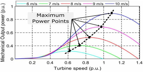
Figure 2.
Maximum mechanical output power points for different wind speeds [].
By replacing if is chosen at the optimum, remains maximum; then, is calculated as follows.
where represents a constructional constant. Considering Figure 2, (5) ensures the MPPT operation as the power transfer occurs from PMSG to the grid without considering the converter losses.
2.2. Diode Rectifier and Boost Converter Modeling
An equivalent circuit of a steady-state, non-salient-type PMSG is shown in Figure 3. Due to permanent magnets positioned in the rotor, PMSGs do not require an excitation current in the stator and are self-excited. The WT drives the shaft and converts mechanical energy into electrical energy in WPCS. There is a variation in induced back EMF in proportion to the rotor speed of the PMSG, which is equated as follows [].
where is the flux linkage amplitude in the stator of the PMSG, and is a constant of construction. PMSG per phase voltage in the steady state is expressed as
where and are the stator resistance and synchronous reactance, respectively, and is the generator current.
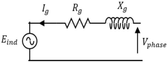
Figure 3.
Single-phase, steady-state equivalent circuit of a PMSG [].
Figure 4 depicts the equivalent circuit of a three-phase steady-state PMSG connected with a diode rectifier and boost converter in the abc frame. In Figure 4, , and are the three-phase induced electromotive voltages, and and are the rectifier output voltage and current, respectively. Under a steady state, the boost converter is modeled as a current source at the diode-rectifier output.
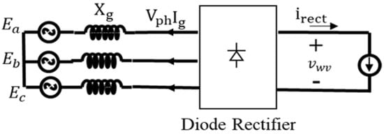
Figure 4.
Steady-state equivalent circuit of a PMSG with a diode rectifier [].
In the absence of diode losses, the rectifier output voltage is formulated as follows:
The first term in (8) is the ideal rectifier average output voltage without taking into account the commutation process, while the second term is the average rectifier voltage drop caused by synchronous reactance.
3. Synchronization of Single-Phase Grid-Connected Inverter
In this section, a dynamically faster prefiltering technique based on a quasi-type-I PLL approach is employed to synchronize a single-phase, grid-tied inverter. First, the prefiltering stage is explored considering the dominant harmonics (i.e., 3rd, 5th, 7th) present in the fundamental grid voltage signal as follows:
Considering (where , i.e., nominal grid frequency), the delay length is considered as . Then, (9) and (10) are combined to obtain an error signal as follows:
Accordingly, Lyapunov’s demodulation principle [] may be applied to obtain time derivatives of state variables and as follows:
where represents a constant gain. The generalized state-space model is expressed as follows:
where and . Note that the signal vector () abides the persistent excitation (PE) property [] if exists and , such that
Therefore, Lyapunov’s estimation law, as described in [], ensures the unboundedness of . In view of the aforementioned constraint, an interesting fact emerges owing to the delay process, which is, itself, very helpful to ensure that the value of is zero. Consequently, strong error boundedness is ensured. For simplicity, consider , the harmonic-free grid voltage signal, and its delayed version as follows:
where , and . Combining (15) and (16) yields
Using (9)–(12) and Lyapunov’s estimation law, for a positive value of , rapid convergence of the estimated variables is also ensured as follows:
Following the delay process, the steady-state error does not exist in the estimated unknown variables (i.e., ). According to the aforementioned analysis and the exact pole-zero cancellation, the odd harmonics present in the grid voltage signal are easily rejected by the operation performed in (5), as depicted in the bode plot shown in Figure 5. However, the proposed approach may not yield proper results for a constant biased grid voltage signal.
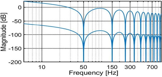
Figure 5.
Magnitude plot for odd-order harmonic cancellation.
3.1. Impact of DC Bias
Let us consider the grid voltage signal contaminated with a constant biased (DC-offset) component as follows:
where the delayed version of (19) is expressed as follows:
Using (8), the error signal is expressed as follows:
The state variables are rewritten using (12) as follows:
It can be easily inferred that the unknown DC bias voltage yields full-cycle (FC) oscillations, affecting the dynamic performance. Note that Equation (21) is very useful to estimate the DC-offset component present in the grid voltage signal, since , which yields
Once is known from (23), rejection of the DC-offset component in the output of the prefilter is possible.
3.2. Post-DC Bias Cancellation from Signals
The proposed prefilter is robust against odd-order harmonic cancellation but is susceptible to DC-offset components in the grid voltage signal. The DC offset bypasses the consecutive stages of the prefilter, yielding a negative impact on both components obtained after inverse Park transformation. One possible solution to make the prefilter insensitive to DC bias is to introduce additional filters in the second stage of the proposed structure, such as:
where is also known as the delayed signal cancellation operator, and is the number of samples in one fundamental cycle.
This process yields stronger attenuation of the harmonics. However, it may cause additional delays in estimating the components. To obtain a computationally simpler solution, further efforts are required. Therefore, the simple approach as indicated by (21) can be applied. In an offline mode, the delayed signal process can be reapplied to both the components as follows:
where and are the DC-offset components present in the fundamental signals. DC bias attenuation factors can be obtained using (23) in offline mode and considering a one p.u. DC offset as follows:
where the attenuation factors () and () are the fixed constant as shown in Figure 6. The attenuation factors for a simulation environment with various values of the DC-offset component existing in the grid voltage signal are plotted as shown in Figure 7. It is easy to infer that the components are unequally affected by the DC-offset component.
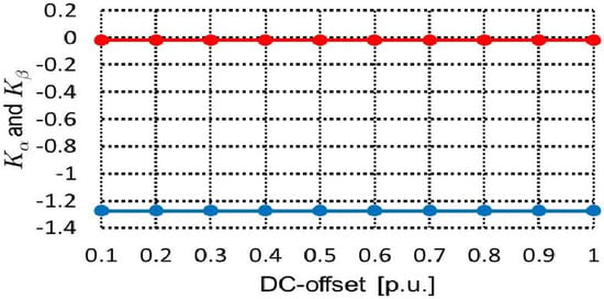
Figure 6.
Graphical representation of attenuation factors with respect to DC offset.

Figure 7.
Improved Lyapunov prefilter (a) without DC-bias rejection capability and (b) with DC-bias rejection capability.
Thus, the attenuation factors (red) and (blue) in Figure 6 are set to −0.0167 and −1.2732, respectively, to yield DC-offset-free components as follows:
The discrete-time architecture of the ILP-based orthogonal signal generator (OSG) can be easily constructed as shown in Figure 7. Furthermore, the proposed ILP is compared with a well-known O-PLL [] to verify the potential abilities under adverse grid conditions. In a simulation environment, the grid voltage signal is contaminated with voltage sag and a 0.1 p.u. DC bias, and a THD of is considered, as shown in Figure 8. It can be observed that the proposed ILP has better DC-bias rejection, fast dynamic response, and harmonic rejection abilities than the O-PLL. The delay of the proposed ILP-OSG at is:
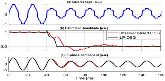
Figure 8.
Amplitude estimation performance of the proposed ILP and O-PLL.
Hence, the proposed ILP can act as a robust prefiltering solution that can rapidly extract the fundamental grid voltage component.
4. Proposed Method
This work focuses on taking advantage of the well-known type-I synchronous reference frame (SRF) phase-locked loop (PLL) owing to its reduced control complexity. Note that only the well-filtered stationary frame components of and can help to avoid the malfunctioning of the proposed PLL; however, as observed in Section 3, the proposed ILP outperforms O-PLL in terms of robustness []. Thus, the outputs of the proposed prefilter can act as inputs to the type-I SRF-PLL. Consequently, the amplitude and phase error can be estimated as follows:
The frame voltages are expressed as
where the actual phase angle information is hidden in the estimated phase . Upon applying quasi phase-lock conditions, (25) is approximated as:
To mitigate the effect of the voltage sags on the estimated grid voltage parameters, can be divided by , which yields the phase-error information as follows:
As shown in Figure 9, the closed-loop phase-error transfer function is expressed as follows:

Figure 9.
Proposed ILP-OSG-based type-I SRF-PLL.
Note that a type-I SRF-PLL behaves as a first-order low-pass filter. Hence, upon applying the final-value theorem, the steady state () is obtained as
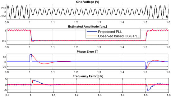
Figure 10.
Dynamic performance comparison of O-PLL and the proposed PLL.
5. Leveraging the Proposed PLL for Implementation the LVRT Strategy
Under the low penetration of a WPCS, an MPPT scheme based on the perturb-and-observe method is employed to control the boost converter. For higher penetration of renewable energy resources in the utility grid, a large ratio makes the low-voltage feeder network resistive in nature. Depending on the droop characteristics, a wind energy system (Figure 2) can switch between reactive power injection mode and unity power factor mode by simply varying the duty cycle of the boost converter, known as non-MPPT (N-MPPT) mode, specific to grid faults. In order to maintain a unity power factor mode, the injected grid current must be synchronized with the grid voltage, indicating that the PMSG-based WPCS is operating normally.
5.1. Inverter Control
Dual-loop inverter control consisting of an outer control loop to control the DC-link voltage is preferred. Consequently, control is performed by a simple proportional integral control as follows:
where the control gains are and . The single-phase theory is applied for the generation of reference current . A proportional resonant (PR) and repetitive controller (RC) [] help in constructing the current controller (CC). as expressed below:
where and are the proportional and resonant control gains for the PR controller, respectively, the fundamental grid frequency is denoted by , is the RC gain, is a low-pass filter, and is a phase-lead compensator that has a phase compensation time denoted by .
An orthogonal signal generation approach [] is always preferred for single-phase renewable energy systems to calculate the power injected by the system, as expressed below:
The aforementioned orthogonal voltage signals, i.e., and , and their respective current signals, i.e., and , are obtained using the proposed ILF-OSG-based approach.
5.2. LVRT Controller
The implementation of the LVRT controller is shown in Figure 11. The fundamental amplitude is estimated using the proposed ILF-OSG as follows:
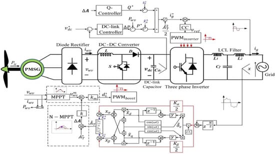
Figure 11.
Overall control structure for a small, single-phase wind turbine system with LVRT capability.
According to the characteristic curves for the wind energy system, switching between MPPT and N-MPPT modes takes place by varying the duty in the event of grid fault. For this purpose, a proportional gain () is introduced, which can adjust the duty cycle of the DC-DC converter.
Under normal operating conditions, the MPPT algorithm yields a maximum operating wind voltage , and by utilizing the conversion factor , the duty cycle ratio is obtained to sufficiently inject the required amount of active power to the grid, indicating . On the other hand, during short-term faults occurring in the grid, the changes from the reference value, i.e., , resulting in . Consequently, varies according to the N-MMPT loop, and the duty cycle varies, which directs the DC-DC converter to reduce the active power production in order to help the inverter control the amount of reactive power injected to the grid under faulty conditions. Note that the inverter has a limited capacity to deliver reactive power to the grid, as denoted by
where the maximum apparent power is , and is the active power. N-MPPT mode is only invoked when and change linearly, considering recovery from the grid fault while improving the voltage profile and protecting the inverter from overcurrent shutdown. Therefore, a constant current strategy is utilized in the current proposal for the safe operation of the inverter. Figure 11 shows the -frame-based control architecture. Hence, a higher degree of control flexibility is offered by the proposed approach, which is not only useful for synchronizing single-phase power converters but can also help to meet LVRT requirements.
6. Experimental Results
In this section, the experimental results are subdivided by considering the grid synchronization operation and the validation of the fault ride using the proposed approach for a PMSG-based WPCS. For this purpose, the component-level system is emulated using an OPAL-RT platform (OP5700), and the system parameters are presented in Table 1. Using an automatic code generation approach and a fixed sampling frequency helps to easily deploy the control algorithm to the dSPACE platform (DS1104), which acts as a real-time controller, as shown in Figure 12. The controller tuning parameters are provided in Table 2.

Table 1.
Parameters for the WPCS under consideration.
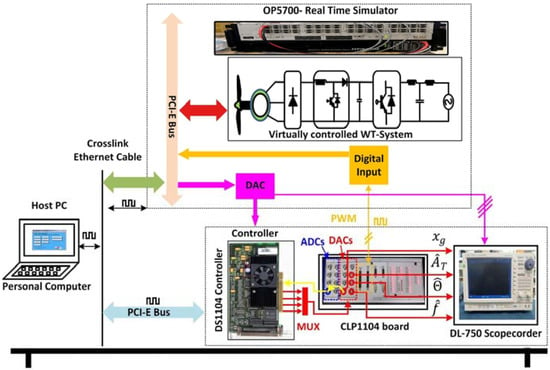
Figure 12.
Experimental test bench setup for the real-time controller and the WT system.

Table 2.
Parameters for the Controllers used.
Initially, the early verification of the synchronization ability of the O-PLL and proposed ILP-PLL is validated in the presence of harmonically distorted grid voltage conditions using the DS1104 controller.
The grid voltage signal is synthesized internally within the real-time controller with nominal parameters of 1 p.u., , and THD. The harmonically distorted grid voltage signal is subjected to voltage, along with a phase jump and 0.1 p.u. DC offset. The aforementioned grid voltage condition is emulated within the controller using a digital-to-analog converter (DAC), then sent to the proposed ILP-PLL, as well as the O-PLL using an analog-to-digital converter (ADC). Accordingly, the grid voltage parameters are captured on a scopecorder (DL750).
Unlike the O-PLL, the proposed ILP-PLL is capable of effectively eliminating the negative effects of harmonics and the DC offset existing in the grid voltage signal, as shown in Figure 13b, Figure 14 and Figure 15b. Robust performance is also ensured under highly adverse grid conditions, demonstrating the fast phase synchronization and amplitude-tracking abilities of the proposed ILP-PLL (in red) in comparison to the O-PLL approach (in blue) in Figure 13b, Figure 14 and Figure 15b.

Figure 13.
(a) Fundamental amplitude-tracking performance in the presence of DC offset, harmonics, and phase jump (b) Performance comparison.

Figure 14.
(a) Phase angle jump-tracking performance at +30° in the presence of DC offset and harmonics. (b) Performance comparison.

Figure 15.
(a) Nominal frequency-tracking ability in the presence of DC offset, harmonics, and phase jump. (b) Performance comparison.
The slow convergence rate of O-PLL towards the steady state indicates that ILP-PLL is well-suited for enhanced control of PMSG-based WPCS, owing to its faster dynamic behavior.
To further assess the importance of the proposed approach, two test case studies are considered as follows:
6.1. Case Study 1: Control Evaluation of PMSG-WPCS under Wind Speed Variation
In this case study, a step change in the wind speed of the PMSG turbine is introduced to determine the stable operating behavior of the overall system. The wind speed changes from to , then back to , as shown in Figure 16a. Note that the generator speed is easily tracked in accordance with the wind speed variations. Moreover, in both the steady and the transient states, the DC-link voltage is tightly maintained at , as demonstrated in Figure 16b. Consequently, when positive variation in wind speed occurs from , the increase in the grid current amplitude is obvious (see Figure 16c). Simultaneously, in view of the unity power factor operation of the PMSG-based turbine, the active power injection into the grid increases, without any injection the reactive power, as shown in Figure 16d. Thus, the stable operating behavior of the PMSG-WPCS is ensured with the proposed control solution.
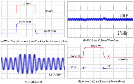
Figure 16.
WPCS analysis under wind speed step variations.
6.2. Case Study 2: LVRT Performance under Voltage Sag Condition on the Grid
To evaluate the performance of the enhanced synchronization control scheme, a voltage sag is introduced on the grid side of the PMSG-based WPCS under study. The PMSG-WPCS’s response to various parameters under grid fault is reported, both with and without applying the proposed constant current control technique. The single-phase PMSG-based WPCS is subjected to grid voltage sag of about 0.35 p.u., as demonstrated in Figure 17a,b. As shown in Figure 17c, without the employment of the LVRT controller, the system is incapable of injecting the required amount of reactive power to support the grid.
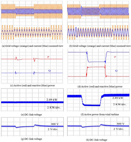
Figure 17.
Experimental results without LVRT control (left) [(a,c,e,g)] and with (right) LVRT control [(b,d,f,h)].
A reduction in active power production is not possible, since the wind turbine system is unaware of the grid voltage sag, as shown in Figure 17e. Thus, undesired active power production continues, which further indicates the need to make use of the additional protection circuits to safeguard the PMSG-based WPCS under grid fault conditions. Note that the grid voltage and current are in-phase indicative of real power generation, even under faulty grid conditions, which is not desirable. Unsafe inverter operation can also take place, which may damage the inverter switches due overcurrents in the event of severe grid fault conditions, owing to the lack of control over the injected grid current. With the employment of the proposed LVRT strategy, a smooth reactive power injection is possible during grid fault (Figure 17d), and a constant lagging current can be easily injected to the grid, as depicted in Figure 17b. The active power production from the wind turbine can also be easily controlled with the incorporation of the proposed smart LVRT approach, as shown in Figure 17f. Furthermore, the WPCS manages to avoid overcurrent from the inverter and maintain the DC-link voltage value at its nominal value as desired (Figure 17g,h). Finally, once the voltage sag is cleared, the WPCS resumes normal operating behavior and attempts to track the maximum active output power from the wind turbine by delivering reference active power with no reactive power delivery.
6.3. Comparative Evaluation of Grid Current
The LVRT controller is re-evaluated using the observer-based PLL and the proposed ILP-PLL, as shown in Figure 18. The grid voltage experiences 0.3 p.u. of voltage sag, as shown in Figure 18a,b. The proposed control strategy is applied to maintain a constant current before and after the fault conditions. Under nominal operating conditions, the harmonic distortions in the grid current are below 3%, as per the grid standard for both the observer-based approach and the proposed ILP-PLL approach. Figure 18c infers that the observer-based technique is sensitive to the presence of harmonics; as a result, THD is observed under fault conditions. Unlike the observer-based PLL approach, the control approach comprising the proposed ILP-PLL can still maintain a total harmonics distortion (THD) level below the recommended value, i.e., 2.74%. Notably, power delivery operation to the grid is offered by both schemes in the event of grid voltage sag, as exemplified in Figure 18e,f. However, due to the increase in the THD of the grid current, the observer-based control approach is unable to correctly inject the required amount of reactive power into the grid as compared to the proposed control scheme. Hence, the proposed control solution offers a dynamically preferrable solution to enhance the fault ride through the capability of the small PMSG-based WPCS.
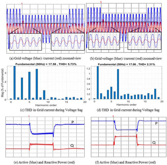
Figure 18.
Comparative performance evaluation of the O-PLL control approach (left) [(a,c,e)] and with (right) proposed ILP control scheme [(b,d,f)].
7. Conclusions
This paper reports an improved control functionality feature for a small wind turbine PMSG-WPCS subjected to unhealthy grid conditions deeply polluted with harmonics. To improve the control flexibility, an improved Lyapunov PLL (ILP-PLL) approach is proposed, which is able to rapidly reject the harmonics and DC-offset components existing in the grid voltage signal compared to the well-known observer-based PLL. The dynamic response of one-half of the fundamental cycle is a key strength required to rapidly synchronize the grid-tied inverter with the help of ILP-PLL. Nevertheless, the proposed prefiltering solution can act as an amplitude detector unit, which helps to easily accommodate the constant current LVRT strategy for the PMSG-based WPCS. Consequently, the aforementioned smart decision-making ability is possibly accommodated in the converter control for improved injection of the required amount of reactive current with lower total harmonic distortions. Finally, the real-time experimental results corroborate the fact that the proposed ILP-PLL approach outperforms the conventional O-PLL under all dynamic grid voltage conditions. Unlike O-PLL, the proposed ILP-PLL contributes to overall control by tightly controlling the DC-link voltage and accurately injecting the required amount of reactive power to the grid. Thus, the proposed control solution is a well-suited approach for small wind-turbine-based PMSG-WPCS. Nevertheless, there is still work to be done in terms of the study of the stability of the prefiltering stage in the architectural sense to improve the proposed scheme under different grid conditions. Likewise, to improve LVRT capabilities, efforts can be made to further minimize the detection time for voltage sag.
Author Contributions
S.W.A.: investigation, conceptualization, methodology, software, and writing—original draft; C.-L.S.: supervision, writing—review and editing; A.K.V.: conceptualization, methodology, and validation; C.B.M.: writing—review and editing; C.G.-C.: writing—review and editing. All authors have read and agreed to the published version of the manuscript.
Funding
This work was funded by the Ministry of Science and Technology of Taiwan under grant MOST 110-2221-E-992-044-MY3.
Institutional Review Board Statement
Not applicable.
Informed Consent Statement
Not applicable.
Data Availability Statement
Not applicable.
Conflicts of Interest
The authors declare no conflict of interest.
References
- Xie, J.B.; Fu, J.X.; Liu, S.Y.; Hwang, W.S. Assessments of Carbon Footprint and Energy Analysis of Three Wind Farms. J. Clean. Prod. 2020, 254, 120159. [Google Scholar] [CrossRef]
- Ahmad, S.S.; Al Rashid, A.; Raza, S.A.; Zaidi, A.A.; Khan, S.Z.; Koç, M. Feasibility Analysis of Wind Energy Potential along the Coastline of Pakistan. Ain Shams Eng. J. 2022, 13, 101542. [Google Scholar] [CrossRef]
- Kaldellis, J.K.; Apostolou, D. Life Cycle Energy and Carbon Footprint of Offshore Wind Energy. Comparison with Onshore Counterpart. Renew. Energy 2017, 108, 72–84. [Google Scholar] [CrossRef]
- Ali, S.W.; Sadiq, M.; Terriche, Y.; Naqvi, S.A.R.; Hoang, L.Q.N.; Mutarraf, M.U.; Hassan, M.A.; Yang, G.; Su, C.L.; Guerrero, J.M. Offshore Wind Farm-Grid Integration: A Review on Infrastructure, Challenges, and Grid Solutions. IEEE Access 2021, 9, 102811–102827. [Google Scholar] [CrossRef]
- Yao, J.; Pei, J.; Xu, D.; Liu, R.; Wang, X.; Wang, C.; Li, Y. Coordinated Control of a Hybrid Wind Farm with DFIG-Based and PMSG-Based Wind Power Generation Systems under Asymmetrical Grid Faults. Renew. Energy 2018, 127, 613–629. [Google Scholar] [CrossRef]
- Yu, J.; Li, J.; Hu, W.; Zhang, G.; Wang, H.; Huang, Q.; Chen, Z. Small-Signal Modeling of Wind Farm with Direct-Drive PMSG Using the Component Connection Method. Energy Rep. 2021, 7, 334–342. [Google Scholar] [CrossRef]
- Artal-Sevil, J.S.; Dufo, R.; Dominguez, J.A.; Bernal-Agustin, J.L. Small Wind Turbines in Smart Grids. Transformation of Electrical Machines in Permanent Magnet Synchronous Generators. In Proceedings of the 2018 Thirteenth International Conference on Ecological Vehicles and Renewable Energies (EVER), Monte Carlo, Monaco, 10–12 April 2018; pp. 1–8. [Google Scholar] [CrossRef]
- Tang, Z.; Yang, Y.; Blaabjerg, F. Power Electronics: The Enabling Technology for Renewable Energy Integration. CSEE J. Power Energy Syst. 2022, 8, 39–52. [Google Scholar] [CrossRef]
- Fathy, A.; Alharbi, A.G.; Alshammari, S.; Hasanien, H.M. Archimedes Optimization Algorithm Based Maximum Power Point Tracker for Wind Energy Generation System. Ain Shams Eng. J. 2022, 13, 101548. [Google Scholar] [CrossRef]
- Nguyen, T.H.; Lee, D.C. A Novel Current Control Scheme of Grid Converters for Small PMSG Wind Turbines under Grid Voltage Distortion. In Proceedings of the 2012 IEEE Power Electronics and Machines in Wind Applications, Denver, CO, USA, 16–18 July 2012. [Google Scholar] [CrossRef]
- Li, H.; Shi, K.L.; McLaren, P.G. Neural-Network-Based Sensorless Maximum Wind Energy Capture with Compensated Power Coefficient. IEEE Trans. Ind. Appl. 2005, 41, 1548–1556. [Google Scholar] [CrossRef]
- Hu, W.X.; Xiao, X.Y.; Zheng, Z.X. Voltage Sag/Swell Waveform Analysis Method Based on Multi-Dimension Characterisation. IET Gener. Transm. Distrib. 2020, 14, 486–493. [Google Scholar] [CrossRef]
- Döşoğlu, M.K. Enhancement of LVRT Capability in DFIG-Based Wind Turbines with STATCOM and Supercapacitor. Sustainability 2023, 15, 2529. [Google Scholar] [CrossRef]
- López, J.; Sanchis, P.; Roboam, X.; Marroyo, L. Dynamic Behavior of the Doubly Fed Induction Generator during Three-Phase Voltage Dips. IEEE Trans. Energy Convers. 2007, 22, 709–717. [Google Scholar] [CrossRef]
- Gencer, Ö.; Öztürk, S.; Erfidan, T. A New Approach to Voltage Sag Detection Based on Wavelet Transform. Int. J. Electr. Power Energy Syst. 2010, 32, 133–140. [Google Scholar] [CrossRef]
- Jaalam, N.; Rahim, N.A.; Bakar, A.H.A.; Tan, C.K.; Haidar, A.M.A. A Comprehensive Review of Synchronization Methods for Grid-Connected Converters of Renewable Energy Source. Renew. Sustain. Energy Rev. 2016, 59, 1471–1481. [Google Scholar] [CrossRef]
- Sahoo, A.; Ravishankar, J.; Jones, C. Phase-Locked Loop Independent Second-Order Generalized Integrator for Single-Phase Grid Synchronization. IEEE Trans. Instrum. Meas. 2021, 70, 1–9. [Google Scholar] [CrossRef]
- Yang, Y.; Sangwongwanich, A.; Liu, H.; Blaabjerg, F. Low Voltage Ride-through of Two-Stage Grid-Connected Photovoltaic Systems through the Inherent Linear Power-Voltage Characteristic. In Proceedings of the 2017 IEEE Applied Power Electronics Conference and Exposition (APEC), Tampa, FL, USA, 26–30 March 2017; pp. 3582–3588. [Google Scholar] [CrossRef]
- Gude, S.; Chu, C.C.; Vedula, S.V. Recursive Implementation of Multiple Delayed Signal Cancellation Operators and Their Applications in Pre-Filtered and in-Loop Filtered PLLs under Adverse Grid Conditions. In Proceedings of the 2018 IEEE Industry Applications Society Annual Meeting (IAS), Portland, OR, USA, 23–27 September 2018. [Google Scholar] [CrossRef]
- Golestan, S.; Guerrero, J.M.; Musavi, F.; Vasquez, J.C. Single-Phase Frequency-Locked Loops: A Comprehensive Review. IEEE Trans. Power Electron. 2019, 34, 11791–11812. [Google Scholar] [CrossRef]
- Freijedo, F.D.; Yepes, A.G.; López, Ó.; Fernández-Comesaña, P.; Doval-Gandoy, J. An Optimized Implementation of Phase Locked Loops for Grid Applications. IEEE Trans. Instrum. Meas. 2011, 60, 3110–3119. [Google Scholar] [CrossRef]
- Sillapawicharn, Y.; Kumsuwan, Y. An Improvement of Synchronously Rotating Reference Frame Based Voltage Sag Detection for Voltage Sag Compensation Applications under Distorted Grid Voltages. In Proceedings of the 2011 IEEE Ninth International Conference on Power Electronics and Drive Systems, Singapore, 5–8 December 2011; pp. 100–103. [Google Scholar] [CrossRef]
- Karimi-Ghartemani, M.; Khajehoddin, S.A.; Jain, P.K.; Bakhshai, A. Derivation and Design of In-Loop Filters in Phase-Locked Loop Systems. IEEE Trans. Instrum. Meas. 2012, 61, 930–940. [Google Scholar] [CrossRef]
- Golestan, S.; Guerrero, J.M.; Vidal, A.; Yepes, A.G.; Doval-Gandoy, J. PLL with MAF-Based Prefiltering Stage: Small-Signal Modeling and Performance Enhancement. IEEE Trans. Power Electron. 2016, 31, 4013–4019. [Google Scholar] [CrossRef]
- Li, J.; Wang, Q.; Xiao, L.; Hu, Y.; Wu, Q.; Liu, Z. An Aβ-Frame Moving Average Filter to Improve the Dynamic Performance of Phase-Locked Loop. IEEE Access 2020, 8, 180661–180671. [Google Scholar] [CrossRef]
- Ahmed, H.; Biricik, S.; Benbouzid, M. Linear Kalman Filter-Based Grid Synchronization Technique: An Alternative Implementation. IEEE Trans. Ind. Informatics 2021, 17, 3847–3856. [Google Scholar] [CrossRef]
- Abd-Elkader, A.G.; Allam, D.F.; Tageldin, E. Islanding Detection Method for DFIG Wind Turbines Using Artificial Neural Networks. Int. J. Electr. Power Energy Syst. 2014, 62, 335–343. [Google Scholar] [CrossRef]
- Rahmani, M.; Nodozi, I. Phase-Locked Loops Redesign by the Lyapunov Theory. Electron. Lett. 2015, 51, 1664–1666. [Google Scholar] [CrossRef]
- Xiao, F.; Dong, L.; Li, L.; Liao, X. A Frequency-Fixed SOGI-Based PLL for Single-Phase Grid-Connected Converters. IEEE Trans. Power Electron. 2017, 32, 1713–1719. [Google Scholar] [CrossRef]
- Cao, W.; Liu, K.; Kang, H.; Wang, S.; Fan, D.; Zhao, J. Resonance Detection Strategy for Multi-Parallel Inverter-Based Grid-Connected Renewable Power System Using Cascaded SOGI-FLL. Sustainability 2019, 11, 4839. [Google Scholar] [CrossRef]
- Hasan, S.; Muttaqi, K.M.; Sutanto, D. Detection and Characterization of Time-Variant Nonstationary Voltage Sag Waveforms Using Segmented Hilbert-Huang Transform. IEEE Trans. Ind. Appl. 2020, 56, 4563–4574. [Google Scholar] [CrossRef]
- Nasiri, M.; Arzani, A. Robust Control Scheme for the Braking Chopper of PMSG-Based Wind Turbines–A Comparative Assessment. Int. J. Electr. Power Energy Syst. 2022, 134, 107322. [Google Scholar] [CrossRef]
- Chakraborty, A.; Maity, T. Integrated Control Algorithm for Fast and Accurate Detection of the Voltage Sag with Low Voltage Ride-through (LVRT) Enhancement for Doubly-Fed Induction Generator (DFIG) Based Wind Turbines. Control Eng. Pract. 2023, 131, 105393. [Google Scholar] [CrossRef]
- Ahmed, H.; Biricik, S.; Benbouzid, M. Low-Pass Filtering or Gain Tuning Free Simple DC Offset Rejection Technique for Single and Three-Phase Systems. Electr. Power Syst. Res. 2020, 186, 106422. [Google Scholar] [CrossRef]
- Nguyen, T.H.; Al Hosani, K.; Al Sayari, N. Grid Integration Improvement for Single-Phase Inverters of Small Wind Turbines under Distorted Voltage Conditions. Int. J. Electr. Power Energy Syst. 2017, 87, 144–153. [Google Scholar] [CrossRef]
- Hadjidemetriou, L.; Kyriakides, E.; Yang, Y.; Blaabjerg, F. A Synchronization Method for Single-Phase Grid-Tied Inverters. IEEE Trans. Power Electron. 2016, 31, 2139–2149. [Google Scholar] [CrossRef]
- Hadjidemetriou, L.; Kyriakides, E.; Yang, Y.; Blaabjerg, F. A Synchronization Scheme for Single-Phase Grid-Tied Inverters under Harmonic Distortion and Grid Disturbances. In Proceedings of the 2016 IEEE Applied Power Electronics Conference and Exposition (APEC), Long Beach, CA, USA, 20–24 March 2016; pp. 3500–3507. [Google Scholar] [CrossRef]
- Verma, A.K.; Subramanian, C.; Jarial, R.K.; Roncero-Sanchez, P.; Rao, U.M. A Robust Lyapunov’s Demodulator for Tracking of Single-/Three-Phase Grid Voltage Variables. IEEE Trans. Instrum. Meas. 2021, 70, 1–11. [Google Scholar] [CrossRef]
- Zammit, D.; Staines, C.S.; Micallef, A.; Apap, M. Wind MPPT for a PMSG SWT in a Grid-Connected DC Microgrid. In Proceedings of the 2019 6th International Conference on Control, Decision and Information Technologies (CoDIT), Paris, France, 23–26 April 2019; pp. 1006–1012. [Google Scholar] [CrossRef]
- Zhang, X.; Zhang, Y.; Hao, S.; Wu, L.; Wei, W. An Improved Maximum Power Point Tracking Method Based on Decreasing Torque Gain for Large Scale Wind Turbines at Low Wind Sites. Electr. Power Syst. Res. 2019, 176, 105942. [Google Scholar] [CrossRef]
- Rahimi, M. Modeling, Control and Stability Analysis of Grid Connected PMSG Based Wind Turbine Assisted with Diode Rectifier and Boost Converter. Int. J. Electr. Power Energy Syst. 2017, 93, 84–96. [Google Scholar] [CrossRef]
- Robust Adaptive Control—Petros—Google Search. Available online: https://www.google.com/search?q=Robust+Adaptive+Control+-+Petros&rlz=1C1GCEA_enTW987TW988&sxsrf=APwXEdeKQX6XbhhM86hIVv6cVUjOsbJvoA%3A1681715500107&ei=LPE8ZJCUBo_5hwPWmrLwAw&ved=0ahUKEwiQ2vy3rrD-AhWP_GEKHVaNDD4Q4dUDCA8&uact=5&oq=Robust+Adaptive+Control+-+Petros&gs_lcp=Cgxnd3Mtd2l6LXNlcnAQAzIGCAAQFhAeMggIABCKBRCGAzIICAAQigUQhgMyCAgAEIoFEIYDMggIABCKBRCGAzoHCCMQ6gIQJ0oECEEYAFD2Dlj2DmDFFWgBcAF4AIABRYgBRZIBATGYAQCgAQGgAQKwAQrAAQE&sclient=gws-wiz-serp (accessed on 17 April 2023).
- Verma, A.K.; Jarial, R.K.; Rao, U.M.; Roncero-Sanchez, P. A Robust Three-Phase Prefiltered Phase Locked-Loop for the Subcycle Estimation of Fundamental Parameters. IEEE Trans. Ind. Appl. 2021, 57, 6155–6166. [Google Scholar] [CrossRef]
- Stojić, D.; Georgijević, N.; Rivera, M.; Milić, S. Novel Orthogonal Signal Generator for Single Phase PLL Applications. IET Power Electron. 2018, 11, 427–433. [Google Scholar] [CrossRef]
Disclaimer/Publisher’s Note: The statements, opinions and data contained in all publications are solely those of the individual author(s) and contributor(s) and not of MDPI and/or the editor(s). MDPI and/or the editor(s) disclaim responsibility for any injury to people or property resulting from any ideas, methods, instructions or products referred to in the content. |
© 2023 by the authors. Licensee MDPI, Basel, Switzerland. This article is an open access article distributed under the terms and conditions of the Creative Commons Attribution (CC BY) license (https://creativecommons.org/licenses/by/4.0/).