Article

Study on the Influence of Foundation Pit Excavation on the Deformation of Adjacent Subway Tunnel in the Affected Area of Fault Zones

1
College of Architecture and Engineering, Dalian University, Dalian 116622, China
2
School of Mechanics and Engineering, Liaoning Technical University, Fuxin 123000, China
*
Author to whom correspondence should be addressed.
Sustainability 2023, 15(12), 9462; https://doi.org/10.3390/su15129462
Submission received: 11 May 2023 / Revised: 2 June 2023 / Accepted: 5 June 2023 / Published: 12 June 2023
(This article belongs to the Section Sustainable Engineering and Science)

Abstract

:
In order to understand and mitigate the deformation issues caused by the excavation of foundation pits within the influence area of fault zones, ensuring the safety of the subway system and supporting the sustainable development of the city, this paper takes the foundation pit project near the Shenzhen Metro Line 5 in the F1322 fault zone influence area as the research background, and uses theoretical analysis, numerical simulation and on-site measurement and other research methods to carry out in-depth research on the deformation problems of the adjacent subway tunnel caused by the unloading of the foundation pit excavation. The research results demonstrate that by considering the collaborative deformation effect between retaining piles and excavation sidewall soil under the spatial impact of foundation pit excavation and using the Mindlin solution to calculate the additional stress on the sidewall and bottom of the foundation pit, a deformation calculation formula for the tunnel has been established. The impact characteristics of different geological parameter variations on the horizontal and vertical displacements of the tunnel have been analyzed. The sensitivity analysis of maximum tunnel displacement to different geological parameters reveals that the most sensitive factor is the elastic modulus, followed by the internal friction angle, while the cohesion has the least influence. By fitting the data, it has been found that the maximum deformation of the tunnel under composite strata excavation exhibits a good linear relationship with the index bH/L and a prediction formula for the maximum tunnel deformation under this geological condition has been developed. Therefore, the research findings of this study can be utilized to assess the impact of foundation pit excavation on the deformation of subway tunnels under similar geological conditions. They can also be employed to formulate construction monitoring plans and risk management strategies, contributing to the safety of subway systems and the sustainable development of cities.

1. Introduction

In the process of rapid urban construction development, the development and utilization of underground space have become extremely important. Currently, China has the world’s largest urban subway construction market, and various engineering activities near subway tunnels are increasing day by day, among which the construction of foundation pits near subway tunnels has become a top priority. The construction of foundation pits can cause changes in the stress field [1] and displacement field [2] of the stratum, which can generate additional stress and displacement on the adjacent subway structures, affecting the safety and normal use of the subway operation [3,4]. The subway tunnels respond differently to the relative positions, excavation sizes, support forms, and site geological conditions of surrounding foundation pits, indicating that the impact of nearby foundation pit excavation on subway tunnels is complex and variable. Therefore, it is of great theoretical value and engineering significance to carry out research on the deformation effect of foundation pit excavation on adjacent subway tunnels in order to better evaluate and predict this effect [5,6,7].
Moghal et al. [8] conducted consolidation tests on Al-Qatif soil. Prior to the consolidation tests, samples were prepared using each compaction technique at corresponding dry densities, and horizontal and vertical samples were taken from the compacted molds. The extent of expansion under these two conditions was determined, indicating that the anisotropy resulting from different degrees of compaction, compaction methods, and directions had a significant influence on the swelling behavior of Al-Qatif soil. Liu et al. [9] provide a comprehensive review of the latest research findings in four aspects regarding the impact of excavation on existing tunnels located outside and below foundation pits. They discuss the mechanism of the influence of foundation pit excavation on existing tunnels, the affected area of tunnel deformation caused by foundation pit excavation, methods for predicting tunnel deformation under the influence of foundation pit excavation, and methods for controlling the impact of foundation pit excavation on tunnels. They also explore the main unresolved issues and future research directions. Ding et al. [10] present the research progress on the impact of excavation in soft soil foundation pits on existing tunnels. They discuss the current state of research on adjacent construction issues in soft soil foundation pits, including theoretical studies, model experiments, numerical simulations, and field measurements. Dong et al. [11] use numerical simulation methods to verify the deformation patterns of retaining walls and tunnel structures under the influence of foundation pit excavation. They analyze the deformation response of adjacent tunnels under different influencing factors. Yu et al. [12] conduct centrifuge model tests on nearby foundation pit excavation in soft soil areas adjacent to tunnels. They analyze the influence of excavation on tunnel internal forces, deformations, and surface settlements. They then use numerical simulations to determine that the spatial relationship between the foundation pit and the tunnel has the most significant impact on tunnel deformations. Zhang et al. [13] consider the effects of retaining structures and foundation pit spatial effects. They establish a side wall unloading model to calculate additional stresses induced by excavation and introduce a coordinated deformation model for shield tunnel rotation and misalignment. They analyze the deformation of adjacent tunnels caused by excavation using engineering examples. Bian et al. [14] conduct a three-dimensional numerical analysis using a hypoplastic constitutive model considering the small-strain stiffness of soil to reproduce the response of tunnels under lateral excavation. They study the development mechanism of lining cracks, zoning excavation, and the protective role of contiguous walls. Zhang et al. [15] study the deformation patterns of underground pipelines caused by foundation pit excavation. They specifically analyze the influences of pipeline parameters, foundation pit parameters, soil parameters, and underground contiguous walls on pipeline stress, strain, and deformation. Chen et al. [16] carry out a 1:120 centrifuge model test to obtain the influence patterns of horizontal earth pressure, surface settlement, tunnel settlement, and bending moment in the surrounding strata of tunnels under soft clay layers during foundation pit excavation. Additionally, they verify that consolidation and creep deformation are the main causes of tunnel deformation and internal force development after excavation unloading, emphasizing the need to minimize the exposure time of the pit bottom in actual engineering. Wang et al. [17] employ a partition excavation mode of “large pit + strip pits” combined with various control measures to effectively reduce the impact of foundation pit excavation on adjacent subway tunnels. Based on typical engineering geological conditions in Shanghai’s soft soil area, they establish numerous numerical models using three-dimensional finite element methods. They systematically investigate the effects of various measures, including large pit zoning unloading, reinforcement of pit soil, the application of steel support axial force servo systems, and increasing the stiffness of protective structures on the lateral displacement of foundation pit adjacent tunnels. They evaluate the control effects and propose reasonable values for some parameters. It can be observed that the current research mainly focuses on the deformation effects of nearby subway tunnels caused by foundation pit excavation, but there is a lack of consideration for the influence of fault zone geological conditions.
Based on the research analysis of the literature mentioned above, there is currently a wealth of studies on foundation pit engineering projects under complex geological conditions both domestically and internationally. However, research on foundation pit engineering specifically focused on the influence area of fault zones is relatively scarce. Therefore, it is highly necessary to conduct research on the impact of deep foundation pit excavation in fault zone influence areas on the deformation of nearby subway tunnels. This paper is based on a deep foundation pit project in the influence area of the fault zone in Shenzhen City, considering the synergistic effect of pile–soil deformation under the spatial effects of excavation-induced ground movements. The theoretical calculations of tunnel deformation are established based on the Winkler elastic foundation beam model. In addition, the finite element three-dimensional numerical simulation analysis is performed using MIDAS GTS NX 2021 version. Prism and vibrating wire surface strain gauges are installed on the inner surface of the lining by fixing them with expansion bolts. On-site measurements are conducted using total stations and demodulators to monitor tunnel deformation. The aim of this study is to investigate the deformation impact of deep foundation pit excavation on nearby subway tunnels, reveal the response characteristics of tunnel deformation, determine the sensitivity of various geological parameters, and establish a predictive formula for the maximum displacement of the tunnel considering the structural dimensions and geological conditions.

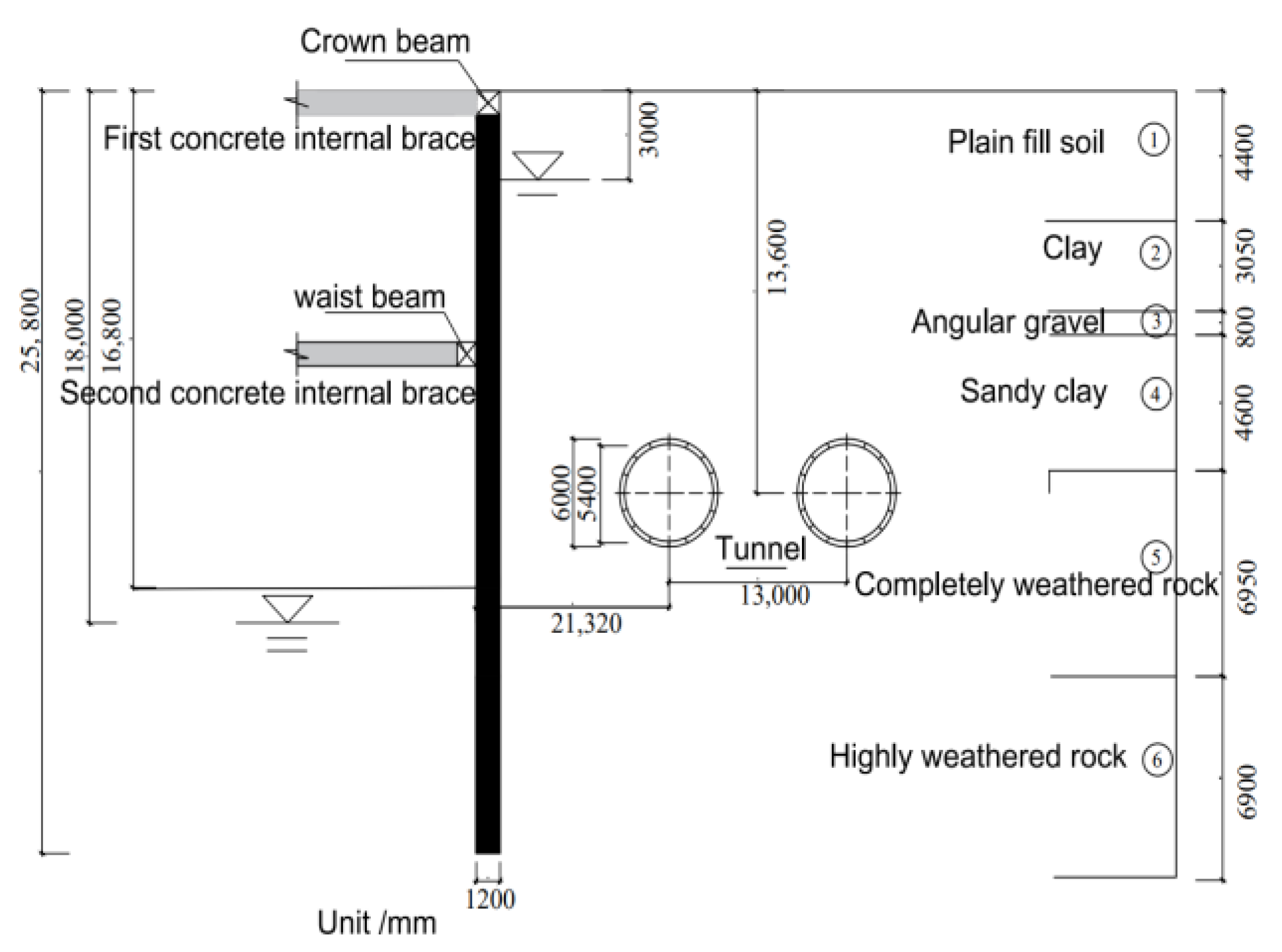
2. Engineering Summary

The project is located on the north side of the tunnel between Yijing Station and Huangbeiling Station of Metro Line 5 in Shenzhen. It is affected by the activity of the Henggang Fault (referred to as the Henggang Fault) in the F1322 (Shehecang-Henggang-Luohu) fault zone. The fault zone is the main fault in the fault group, 38 km long and 7~70 m wide within the city, with a maximum width of about 267 m. The soil parameters were selected based on the investigation report, as shown in Table 1. The geological layers at the site are, from top to bottom: undisturbed soil, with a thickness of 4.4 m; clay, with a thickness of 3.05 m; angular gravel, with a thickness of 0.8 m; sandy clay, with a thickness of 4.6 m; fully weathered mixed rock, with a thickness of 6.95 m; intensely weathered mixed rock, with a thickness of 6.90 m; and moderately weathered mixed rock, which has not been excavated. The maximum excavation depth of the foundation pit is 16.8 m. A pile–internal support structure is used, with two internal supports set at a distance of 8.5 m. The diameter of both the support pile and column pile is 1.2 m. The length of the support pile is 25.8 m, and the length of the column pile is 20.0 m. The cross-sectional size of the crown beam, waist beam, and support beam is 1.0 m × 1.2 m. The concrete strength grade of the support pile, support beam, connecting beam, and column pile is C30. The depth of the tunnel axis is 13.6 m, the outer diameter is 6 m, and the thickness is 0.30 m. The elastic modulus of the pipe segment is 34.5 GPa. The horizontal distance between the center axis of the tunnel and the foundation pit is 21.32 m. The cross-sectional dimensions and physical–mechanical property indicators of the support structure are shown in Table 2. The relative position of the foundation pit and the subway tunnel and the cross-sectional schematic diagram are shown in Figure 1 and Figure 2.

3. Tunnel Deformation Calculation

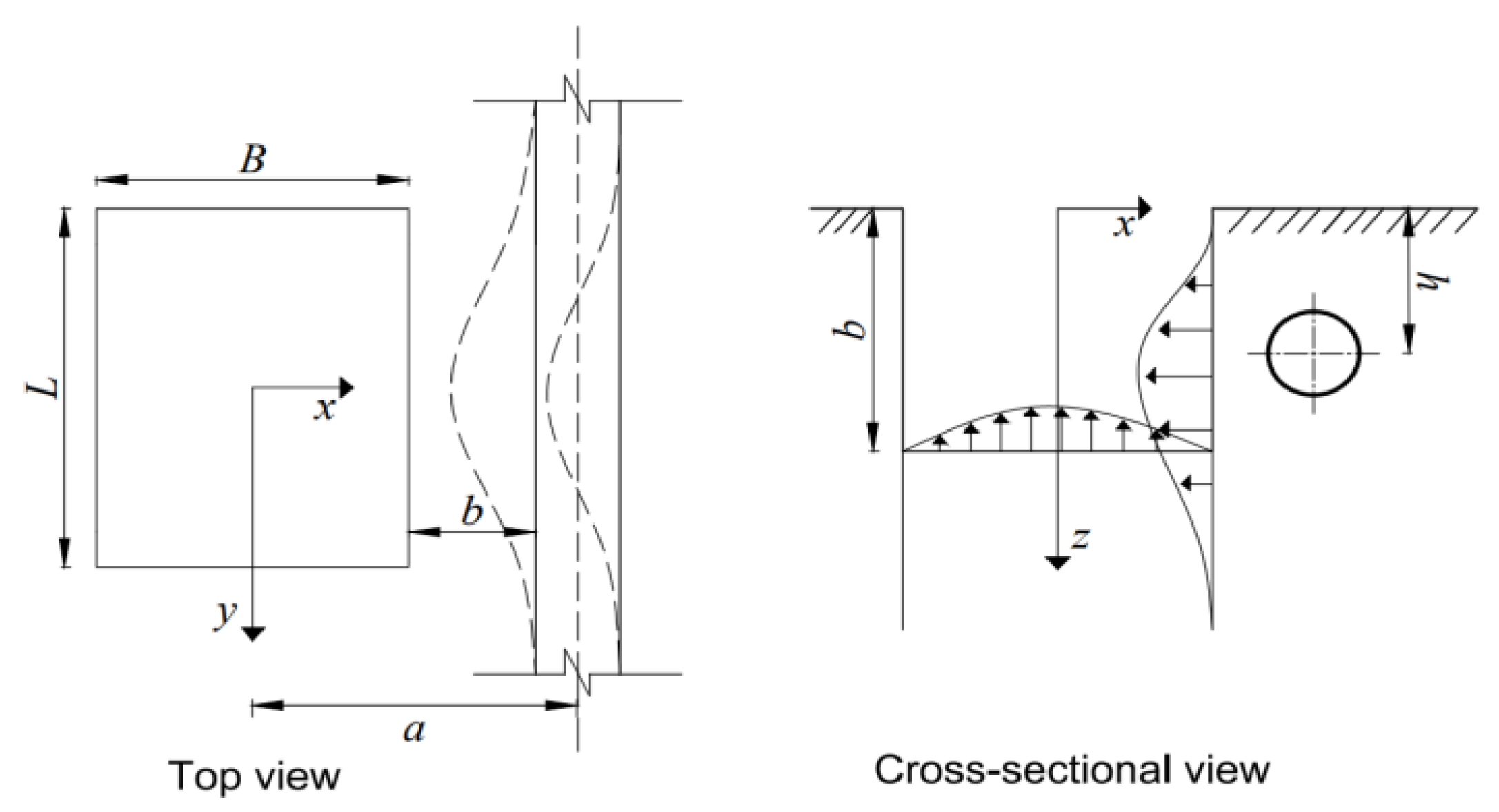
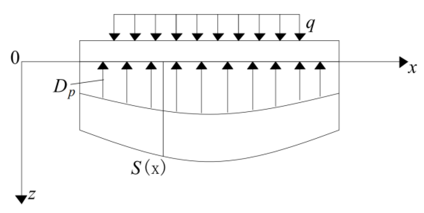
3.1. Calculation of Additional Stress in Tunnel

As shown in Figure 3, a Cartesian coordinate system is established on the ground with the foundation pit as the center. The x-axis and y-axis are perpendicular and parallel to the tunnel axis, respectively, and the z-axis points downward from the foundation pit. The cross-sectional dimensions of the foundation pit are L × B, and the excavation depth is d. The tunnel axis is buried at a depth of z0, and the horizontal distance between the center of the foundation pit and the tunnel axis is a.
As shown in Figure 3, assuming that the soil is homogeneous and elastic half-space and that the tunnel structure is considered as an infinitely long beam under the action of load along the longitudinal direction of the elastic foundation, this paper calculates the horizontal additional stress caused by the excavation of the foundation pit and the vertical additional stress caused by the bottom of the pit based on the Mindlin solution under the synergistic effect of the excavation space effect of the foundation pit and the deformation of the soil and retaining pile.
The stress release around the excavation wall is equivalent to an equivalent distributed load directed toward the excavation. Jiang et al. [18] simplified the calculation by only considering the stress on the adjacent tunnel sidewall. Taking into account the effect of excavation space and the synergistic effect of soil and retaining pile deformation, the stress on the sidewall exhibits a non-linear distribution. Therefore, an infinitely small unit dξdη was selected at the sidewall position (B/2, ξ, η), where the unloading effect was k0γ (L/2 − ξ, η) dξdη. As a result, the horizontal additional stress at any point (x0, y0, z0) on the tunnel axis can be obtained from Equation (1) as Equation (2):
σ = P 8 π ( 1 ν ) ( 1 + 2 ν ) ( z 0 d ) R 1 3 + 3 ( z 0 d ) 3 R 1 5 ( 1 2 ν ) ( z 0 d ) R 2 3 + 30 d z 0 ( z 0 + d ) 3 R 2 7 + 3 ( 3 4 ν ) z 0 ( z 0 + d ) 2 3 d ( z 0 + d ) ( 5 z 0 d ) R 2 5
σ y = k 0 γ ( L / 2 ξ , η ) 8 π ( 1 ν ) D ( 1 2 ν ) ( y 0 B / 2 ) R 1 3 + 3 ( y 0 B / 2 ) 3 R 1 5 ( 1 2 ν ) ( y 0 B / 2 ) · 3 ( 3 4 ν ) y 0 ( y 0 + B / 2 ) 2 3 d ( y 0 + B / 2 ) ( 5 y 0 B / 2 ) R 2 8 + 15 B y 0 ( y 0 + B / 2 ) 3 R 2 7 d ξ d η
Among them:
R 1 = ( x 0 ξ ) 2 + ( y 0 B / 2 ) 2 + ( z 0 η ) 2
R 2 = ( x 0 ξ ) 2 + ( y 0 B / 2 ) 2 + ( z 0 + η ) 2
In the formula, P represents the concentrated force acting on the soil; v represents the Poisson’s ratio; k0 represents the coefficient of static soil pressure; D represents the integral area of the excavation sidewall.
After the excavation of the foundation pit is completed, the stress at the bottom of the pit is released, which is equivalent to a vertically equivalent reverse load, as shown in Figure 3. A small infinite element dξdη is selected from the sidewall (ξ, −L/2, η). At this time, the unloading effect is k0γ (B/2 − ξ, η) dξdη, which means that the additional vertical stress at any point (x0, y0, z0) on the tunnel axis is:
σ z = γ ( B / 2 ξ , η ) 8 π ( 1 ν ) S ( 1 2 ν ) ( z 0 h ) T 1 3 + 3 ( z 0 h ) 3 T 1 5 ( 1 2 ν ) ( z 0 h ) · 3 ( 3 4 ν ) z 0 ( z 0 + h ) 2 3 d ( z 0 + h ) ( 5 z 0 + h ) T 2 8 + 30 h z 0 ( z 0 + h ) 3 T 2 7 d ξ d η
Among them:
T 1 = ( x 0 ξ ) 2 + ( y 0 η ) 2 + ( z 0 h ) 2
T 2 = ( x 0 ξ ) 2 + ( y 0 η ) 2 + ( z 0 + h ) 2
In the formula, S is the integration area of the bottom of the excavation.

3.2. Tunnel Deformation Calculation

As shown in Figure 4, based on the Winkler elastic foundation beam model, the additional stress in the soil is applied back onto the subway tunnel. The tunnel displacement is solved through the longitudinal deformation equation. Considering the coordinated deformation of foundation settlement and beam deflection, according to the classic elastic foundation beam theory, the tunnel structure is viewed as an infinitely long beam under load along the longitudinal direction, and the foundation reaction force P = KS(x). The differential equation for the tunnel structure displacement is obtained as follows:
E I d 4 S ( x ) d x 4 = D p + q ( x ) = K S ( x ) + q ( x )
In the formula, EI is the tunnel stiffness; S(x) is the tunnel displacement; K is the product of the bed coefficient k and D; q(x) is the additional uniform load, the value of which is equal to the product of the vertical additional stress σz and the outer diameter.
Calculated based on mathematical equations:
S ( x ) = e λ x ( C 1 cos λ x + C 2 sin λ x ) + e λ x ( C 3 cos λ x + C 4 sin λ x )
where λ is the foundation stiffness coefficient, λ = K 4 E I 4 .
From the boundary conditions of the tunnel beam displacement, deflection, and load, it can be known that S(x)|x → ∞ = 0, C1 = C2 = 0, and at the location where the concentrated force is applied, x = 0, the slope of the tunnel displacement curve is 0, S(0) = 0, and C1 = C2 = C. Considering the relationship between the shear force and the total foundation reaction of the elastic foundation beam on the right half section, it can be expressed as:
V = d M d X = E I dS 3 d X 3 = F 2
Solve for the value of C and obtain the value of S(x):
S ( x ) = F λ 2 K e λ x ( cos λ x + sin λ x )
Under the action of the additional load q(x) on the tunnel, the concentrated load at any point ξ on the tunnel can be calculated by substituting it into Equation (6) and, integrating within the range of the additional load, the equation for calculating the tunnel structure displacement is obtained as follows:
S ( x ) = λ 2 K q ( ξ ) e λ x ξ ( cos λ x ξ + sin λ x ξ ) d ξ

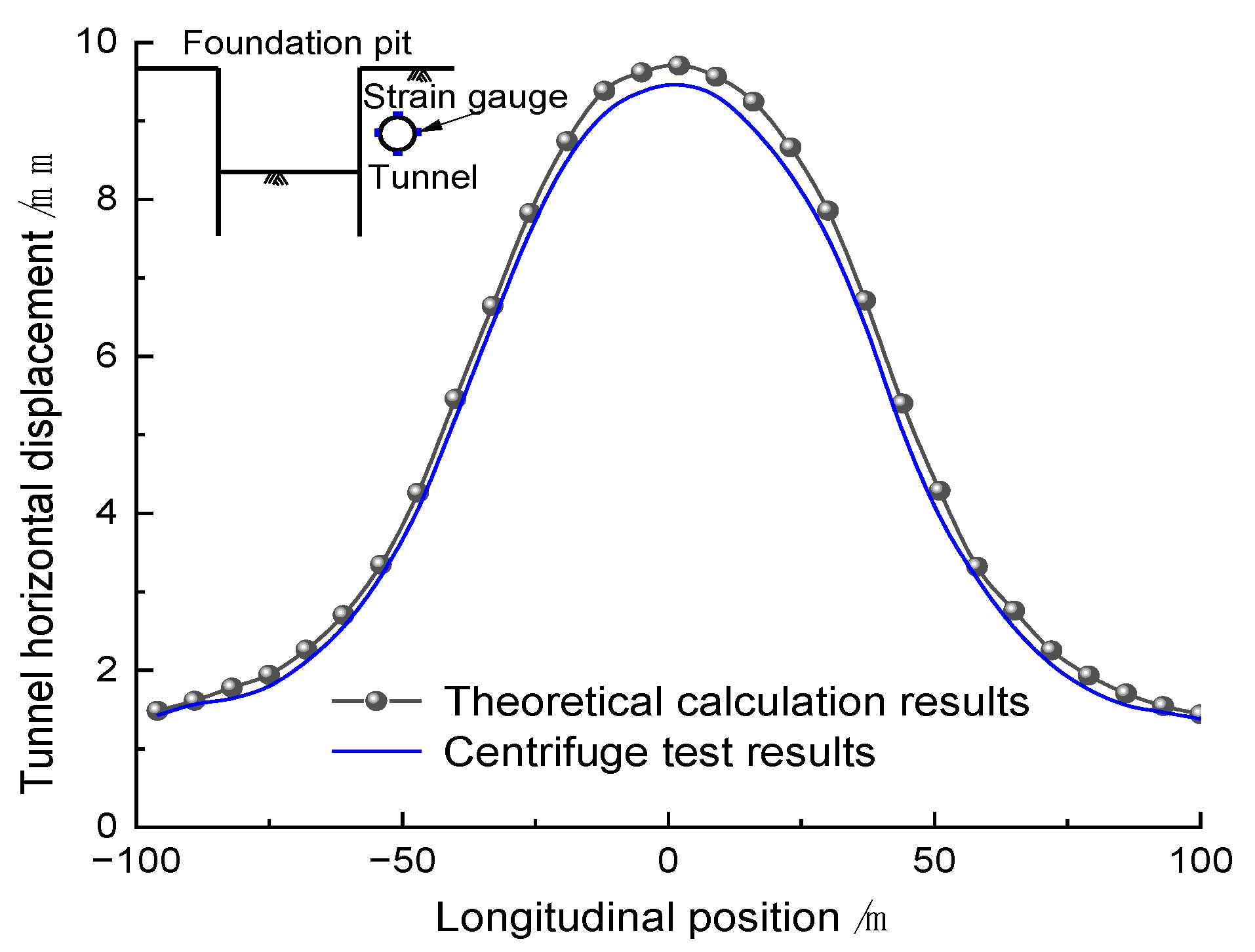
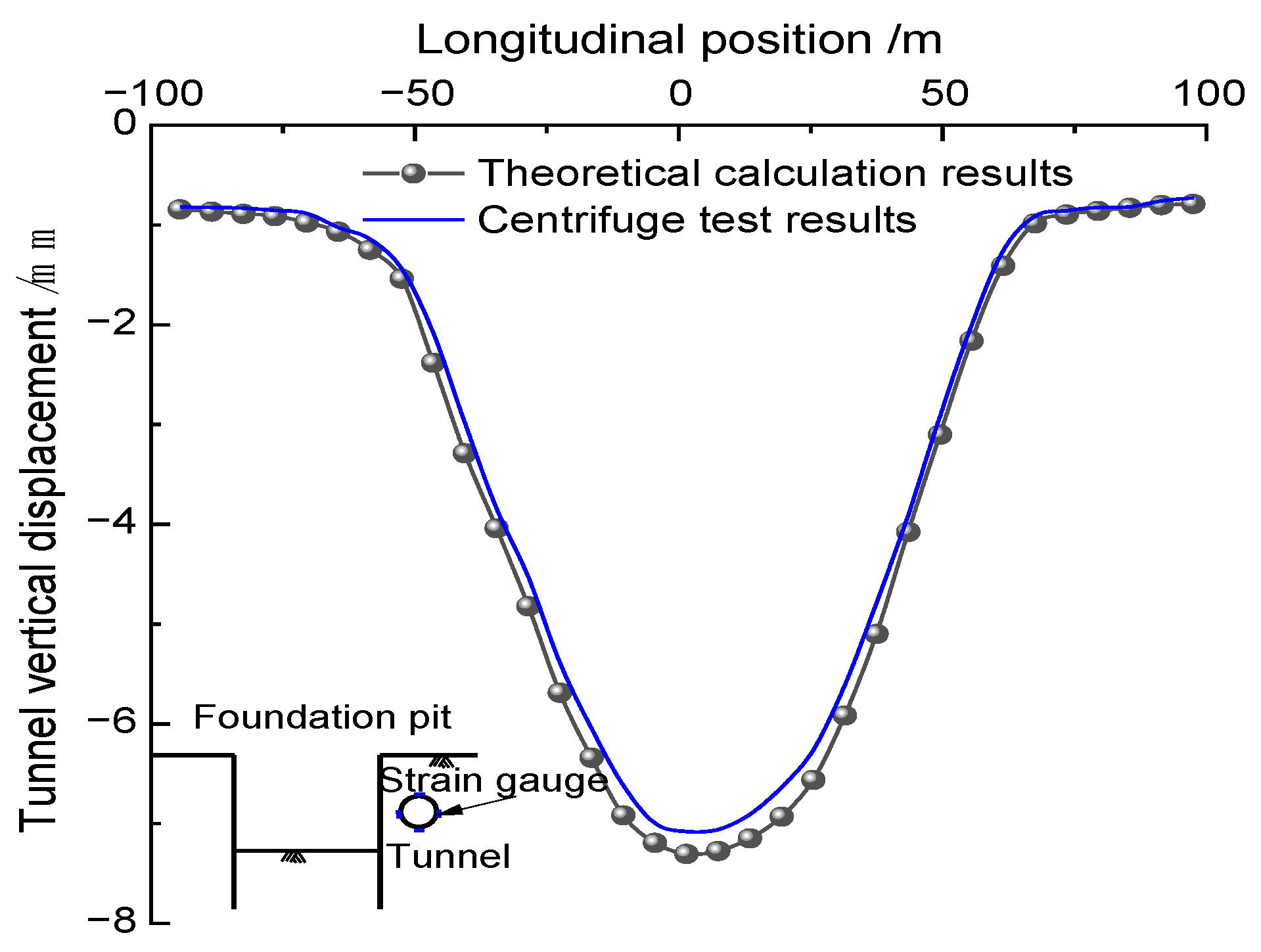
3.3. Centrifugal Experiment Verification

Meng et al. [19] used the ZJU-400 centrifuge of Zhejiang University to study the influence of the excavation of a foundation pit on the lateral tunnel under 60 g centrifugal acceleration. In this study, Shenzhen standard sand was selected with a bulk density of 18.0 kN/m3, relative density of 1.71, specific gravity of 2.7, porosity of 0.40, internal friction angle of 34°, and elastic modulus of 28 MPa. The lateral lying tunnel runs parallel to the foundation pit. The lateral tunnel is longitudinally parallel to the excavation pit. According to the similarity ratio of the centrifugal experiment, this experiment corresponds to a tunnel depth of 13.6 m, an outer diameter of 6 m, a thickness of 0.30 m, an elastic modulus of 34.5 GPa, a horizontal distance of 21.32 m between the tunnel centerline and the foundation pit, a foundation pit excavation depth of 16.8 m, the equivalent continuous wall thickness is 0.88 m, and a height of 25.8 m, with an elastic modulus of 30 GPa. The experiment used the rainfall simulation method to prepare the foundation soil to the height of the tunnel arch and clear out a semi-circular tunnel groove. Then, the tunnel model with strain gauges attached was carefully placed in the groove, and the preparation of the foundation soil was completed from the arch to the top of the model. The entire preparation process strictly ensured close contact between the soil pressure box, the tunnel, and the surrounding sandy clay soil.
As shown in Figure 5 and Figure 6, the experimental measurements of the horizontal and vertical displacements of the tunnel are in good agreement with the calculated results using the Mindlin solution, which takes into account the spatial effect of excavation and the cooperative deformation of the soil and retaining pile. This validates the use of this method to calculate the additional stress and the derived tunnel deformation calculation formula, which is more in line with actual engineering situations. Therefore, the calculation formula provides engineers and planners with an effective tool to assess and predict the impact of excavation on tunnel deformation.

4. Numerical Simulation Analysis

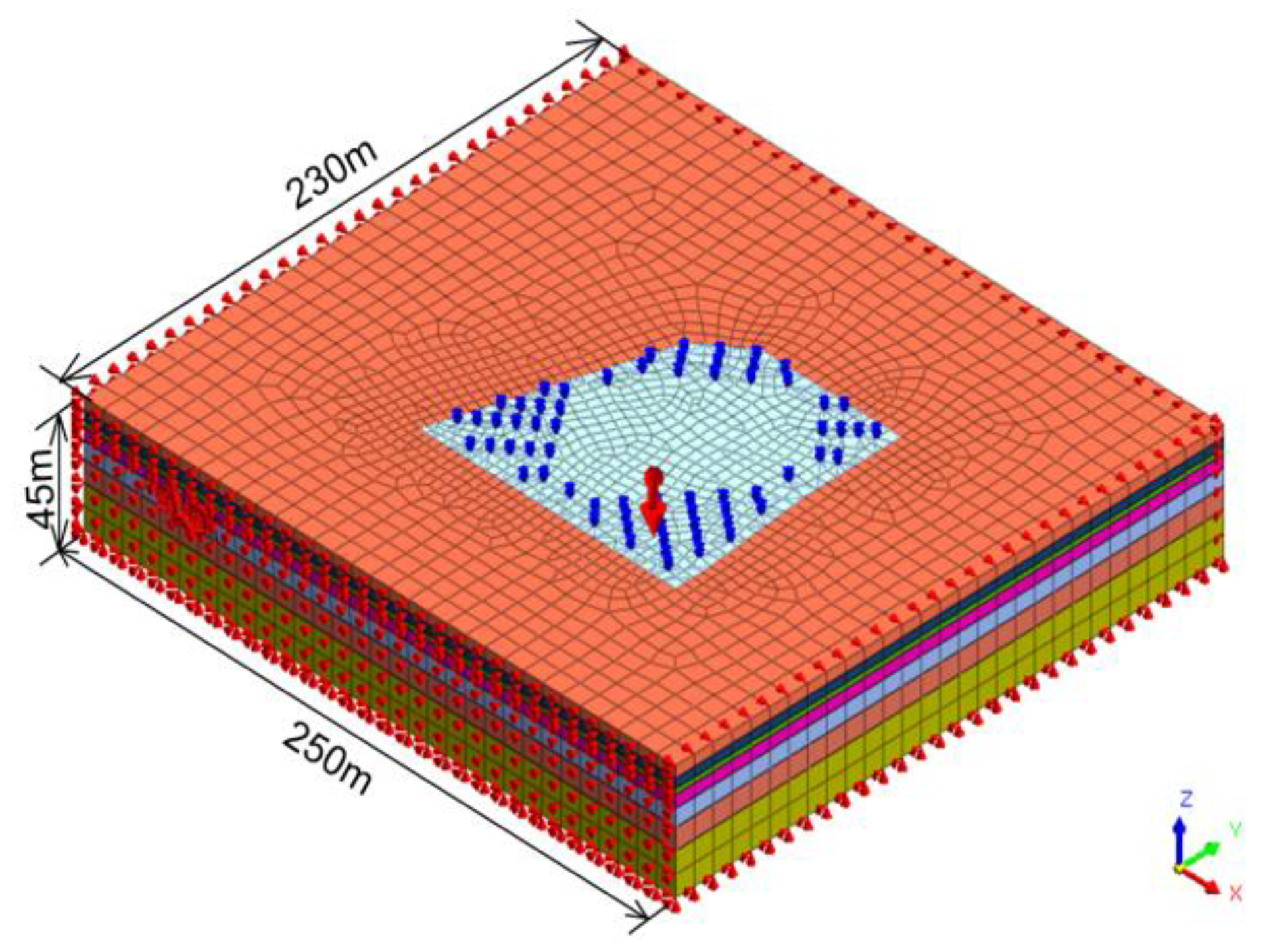
4.1. Three-Dimensional Model Establishment

The three-dimensional analysis model was established using the MIDAS GTS NX finite element software. According to Saint-Venant’s principle, the influence range of the excavation on the surrounding environment is approximately 3 to 5 times the excavation depth. Deformations of the soil beyond this range are small and can be neglected. Therefore, the numerical computational model was selected with dimensions of length × width × height = 250 m × 230 m × 45 m, as shown in Figure 7. Each soil layer was assumed to be an ideal elastic–plastic material obeying the modified Mohr-Coulomb strength criterion. The subway tunnel structure and the retaining structure of the foundation pit were modeled as linear elastic materials. The retaining piles were simulated using an equivalent diaphragm wall with an equivalent thickness of 0.88 m. The tunnel lining and the retaining structure were simulated using shell elements, while the column piles, crown beams, waist beams, and support beams were simulated using 1D beam elements. The entire numerical model consisted of approximately 72,000 finite elements. The relationship between the foundation pit and the tunnel is shown in Figure 8.

4.2. Boundary Conditions

In order to accurately simulate the influence of the foundation pit excavation on the deformation of the adjacent subway tunnel, horizontal constraints were applied to the model around the excavation, and vertical constraints were applied to the bottom to limit the horizontal and vertical displacements before the dynamic simulation calculation of the finite element.

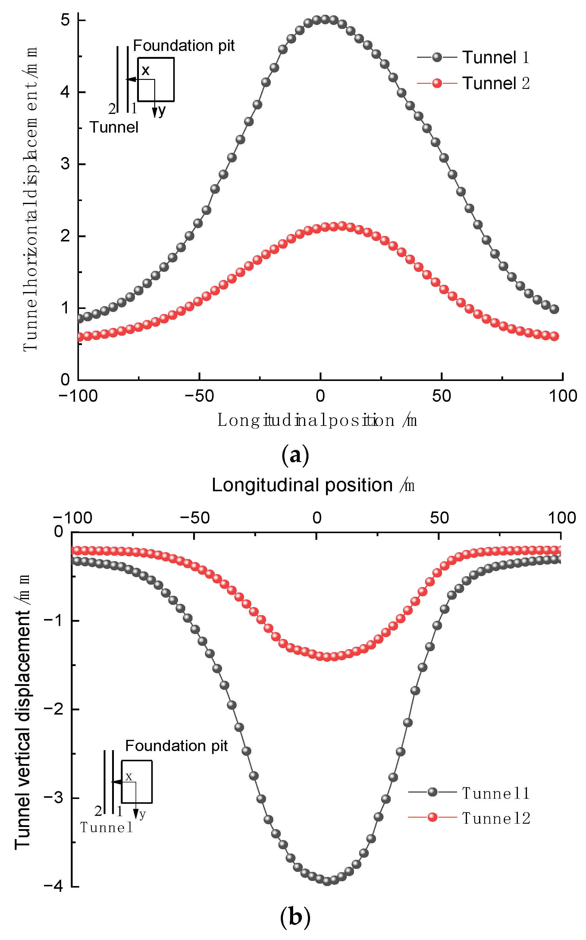
4.3. Analysis of Numerical Simulation Results

The central area (−100 m, 100 m) where the excavation of the foundation pit has a significant impact on the deformation of the tunnel structure was selected. The variation curves of horizontal displacement and vertical displacement of the tunnel structure are shown in Figure 9. The impact of foundation pit excavation on the horizontal and vertical displacement of the adjacent subway tunnel basically follows the normal distribution law. The excavation of the foundation pit destroys the stress equilibrium state of the original stratum, and the soil stress is released. Under the action of additional horizontal stress, the tunnel structure undergoes lateral horizontal displacement, while under the action of additional vertical stress, the tunnel structure undergoes settlement displacement, which means that the “horizontal tensile and vertical compression” trend of the tunnel is intensified.
As shown in Figure 9a, when the excavation of the foundation pit is completed, the maximum horizontal displacement of Tunnel 1 on the near side of the foundation pit is 5.01 mm, significantly larger than that of Tunnel 2 on the far side. This indicates that the excavation of the foundation pit has the greatest impact on the horizontal displacement of the near-side tunnel of the adjacent subway tunnel. As shown in Figure 9b, when the excavation of the foundation pit is completed, the maximum vertical displacement of Tunnel 1 on the near side is 3.94 mm, which is much larger than that of Tunnel 2. At the same time, the maximum horizontal displacement of the tunnel is greater than the maximum vertical displacement, and the maximum displacement values of the tunnel are all less than the allowable value of 10 mm, which meets the safety protection and construction planning control requirements of the subway operation area in Shenzhen.

5. Geological Parameter Impact Analysis

To investigate the influence of varying elastic modulus, internal friction angle, and cohesion on the deformation response characteristics of adjacent subway tunnels, this section adopts the method of controlling variables. By keeping the remaining geological parameters constant, the analysis focuses on the impact of changing one geological parameter. The initial geological parameter settings are detailed in Table 1.

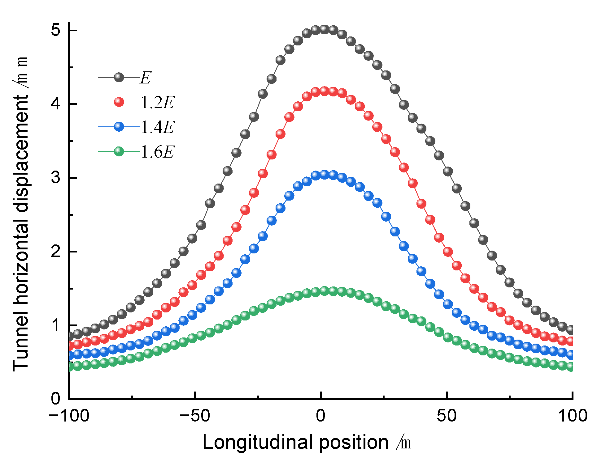
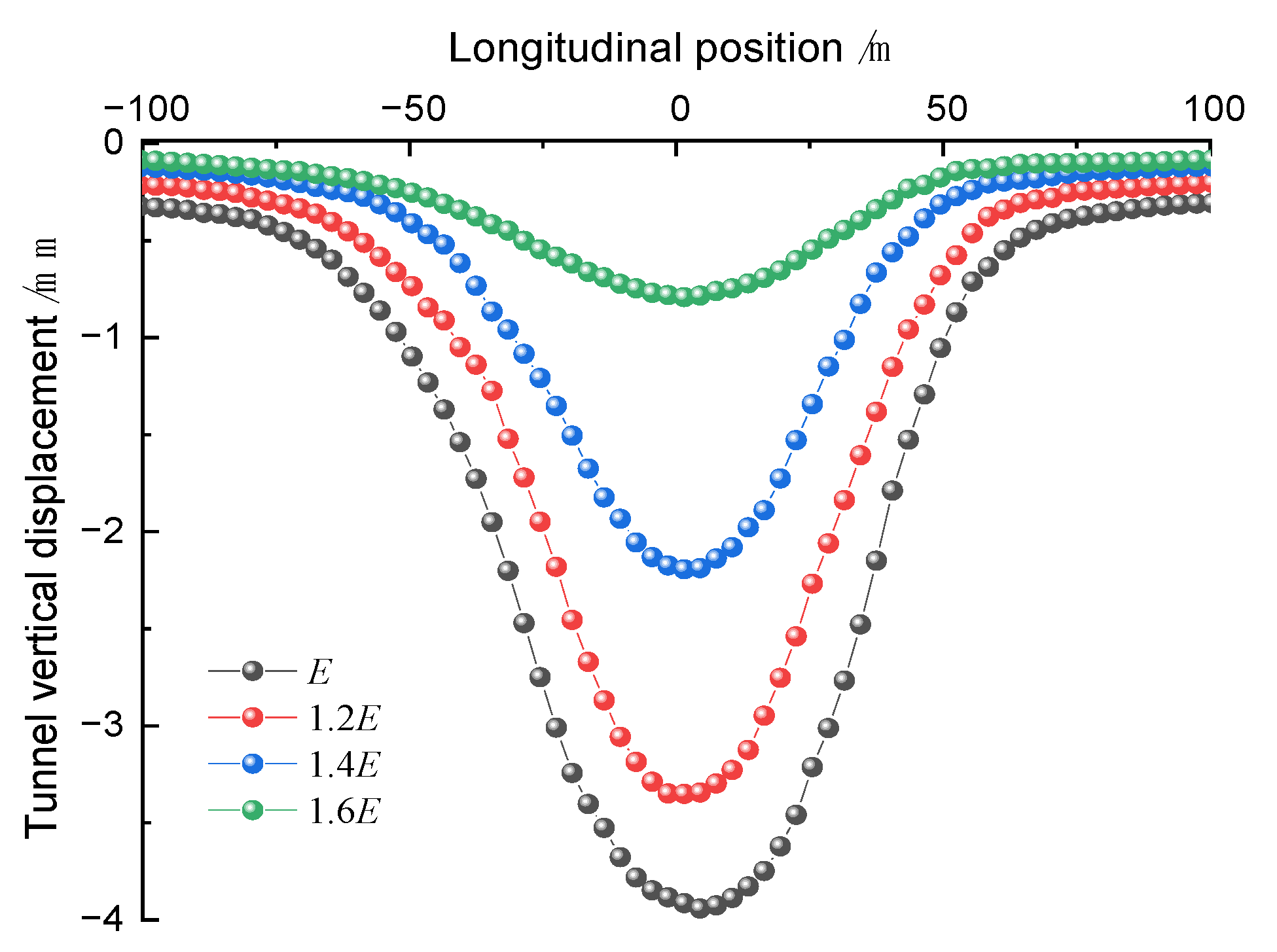
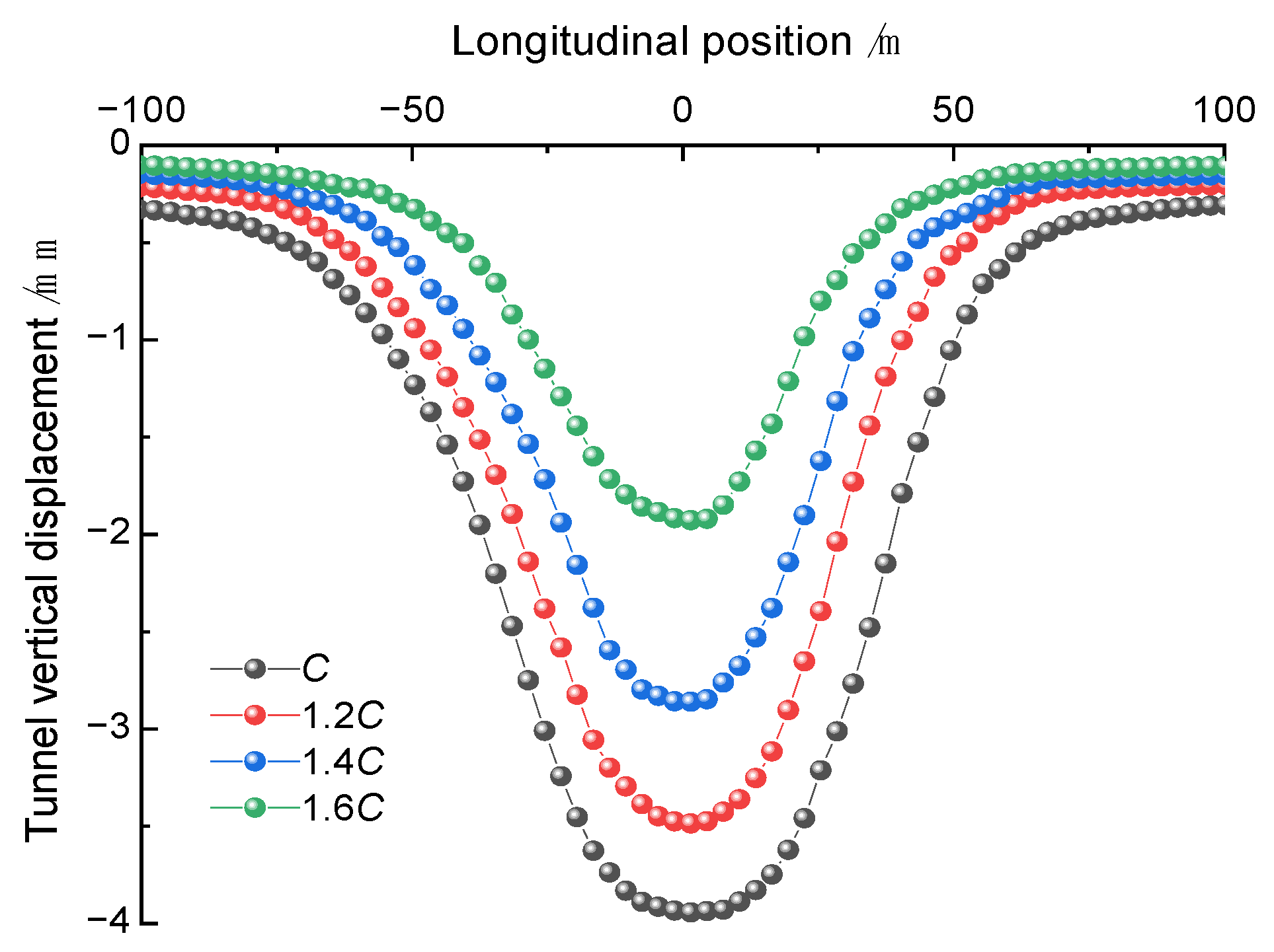
5.1. Impact of Elastic Modulus

Considering the differences in various geological parameters, the deformation response of adjacent subway tunnels varies with changes in parameters. Therefore, based on the original numerical analysis parameters, while keeping other geological parameters constant, the soil elastic modulus is used as the independent variable, and the effects of excavation on adjacent subway tunnel deformation are studied by increasing the soil elastic modulus by 20%, 40%, and 60%. The curve of the variation law of subway tunnel deformation with the increase in soil elastic modulus is shown in Figure 10 and Figure 11.
Under different soil elastic moduli, the lateral and vertical displacements of the tunnel maintain a normal distribution curve law. As the elastic modulus increases, the lateral and vertical displacements of the tunnel simultaneously decrease, and the rate of displacement reduction gradually increases, but the deformation law remains basically the same. The tunnel displacement decreases from the central area of the excavation towards both ends, with the maximum lateral displacement higher than the vertical displacement, indicating that the deformation is mainly lateral.

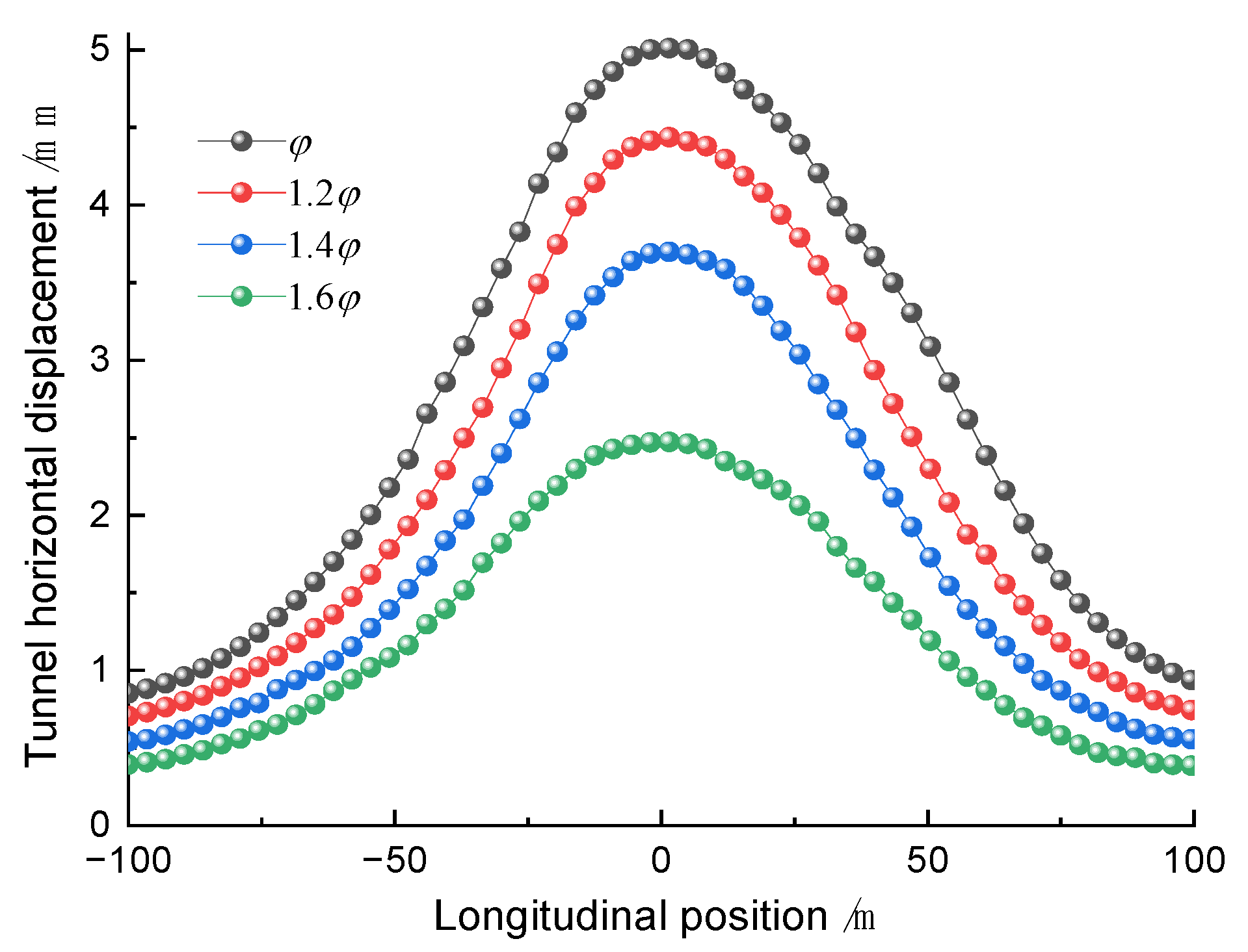
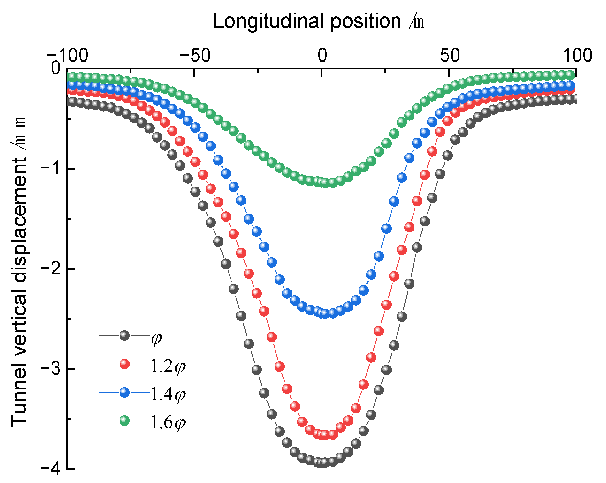
5.2. Impact of Internal Friction Angle

Keeping other parameters constant, the internal friction angle of the soil is increased by 20%, 40%, and 60%, respectively, and the variation law of the adjacent subway tunnel displacement is studied after excavation. The displacement variation of subway tunnels with increasing internal friction angle of the soil is shown in Figure 12 and Figure 13.
Regardless of the internal friction angle, the variation in tunnel displacement is basically the same. As the internal friction angle increases, the frictional force between soil particles increases due to the frictional properties of the soil particles, inhibiting the increase in tunnel displacement and resulting in a decreasing trend in tunnel displacement. The tunnel displacement shows a decreasing trend, and the rate of decrease gradually increases while the deformation pattern remains unchanged. The deformation law remains unchanged. The maximum displacement still occurs in the central area of the excavation, and the rate of change of the vertical displacement is significantly higher than that of the lateral displacement, indicating that the internal friction angle has a higher sensitivity and a greater impact on the vertical displacement of the tunnel.

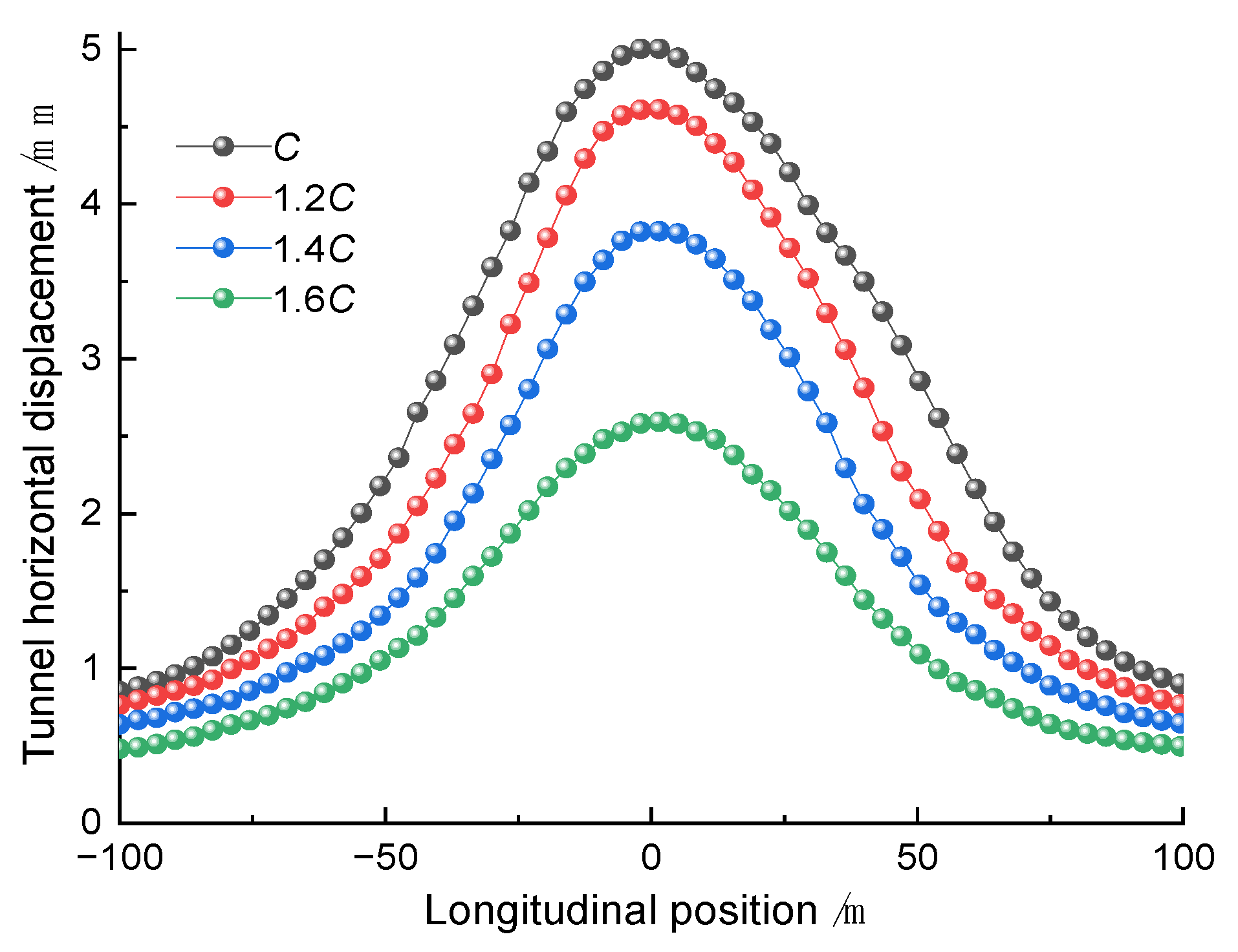
5.3. Impact of Cohesion

Keeping other parameters constant, the soil cohesion is increased by 20%, 40%, and 60%, respectively, and the variation law of the adjacent subway tunnel displacement is studied after excavation. The curve of the variation law of subway tunnel deformation with the increase in soil cohesion is shown in Figure 14 and Figure 15.
Under different cohesion, the variation law of tunnel displacement remains basically the same. As the cohesion increases, the physical and chemical interactions between soil particles are enhanced, resulting in a reduction of soil deformation and a gradual decrease in tunnel displacement, and the rate of displacement reduction also gradually increases. The deformation law remains unchanged. The change in cohesion has a greater impact on tunnel displacement, and the maximum displacement occurs in the central area of the excavation, gradually decreasing towards both ends of the tunnel.

5.4. Sensitivity Analysis

5.4.1. Theoretical Analysis Method

Consider a system γ, determined by n main influencing parameters (α1, α2, α3, …, αn). The relationship between the variable γ and the parameters α is expressed as γ = f (α1, α2, α3, …, αn). Assuming that under certain conditions, the parameters are set to baseline parameters, the baseline variable of the system is obtained as γ′ = f (α1′, α2′, α3′, …, αn′). By adjusting the changes of different influencing parameters on the system variable, the trend and degree of deviation of the system variable γ from the baseline variable γ′ are analyzed, which is called sensitivity analysis [20].
To facilitate sensitivity analysis between different parameters, dimensionless sensitivity functions and sensitivity factors are defined. The ratio of the relative error of γ and αi is defined as the sensitivity function Si (αi), and the approximate expression is given by Equation (8):
S i ( α i ) = d f ( α i ) d ( α i ) α i γ ( i = 1 , 2 , 3 )
Substituting αi′ into Equation (8), the sensitivity factor Sn for αi′ is obtained. In the baseline state, the sensitivity of γ to αi increases with the increase in Sn. By comparing the size of sensitivity factors Sn, different parameters can be analyzed for sensitivity. In this paper, sensitivity analysis is carried out on geological parameters such as elastic modulus E, internal friction angle φ, and cohesive force C.

5.4.2. Analysis of Theoretical Results

The sensitivity comparison curves of different geological parameters to the maximum displacement of the tunnel are shown in Figure 16. Under different geological parameters, the decreasing trend of the maximum displacement of the metro tunnel is not consistent. With the increase in geological parameters, the maximum displacement of the tunnel decreases nonlinearly, and the decreasing rate shows an increasing trend. Among them, the elastic modulus has the most significant impact on the tunnel displacement, followed by the internal friction angle and cohesion.
Based on the geological conditions in this paper, the sensitivity function S(x) of each parameter’s variation to the maximum displacement of the tunnel is obtained with quadratic curve fitting. The sensitivity factor of each geological parameter to the maximum displacement of the tunnel is calculated by Formula (8) and shown in Table 3. The elastic modulus has a more significant impact on the maximum displacement of the tunnel than the internal friction angle and cohesion. It is also found that the sensitivity factor of the internal friction angle to the vertical maximum displacement of the tunnel is greater than that of the horizontal maximum displacement, so an increase in the internal friction angle has a higher sensitivity to the vertical maximum displacement of the tunnel. Considering that the tunnel displacement under the excavation of the foundation pit is mainly in the horizontal direction, the most sensitive geological parameter affecting the tunnel displacement is the elastic modulus, followed by the internal friction angle, and the effect of cohesion is minimal.
Therefore, in the process of geological investigation and engineering design, it is important to focus on the accuracy and rationality of the elastic modulus. The friction angle is also an important geological parameter; although its influence is not as significant as the elastic modulus, it still requires sufficient consideration and evaluation. The impact of cohesive strength is relatively small, so it can be considered a secondary factor in the design process.

6. Comparative Analysis of Numerical, Theoretical, and On-Site Measurement Results

6.1. Layout of Measurement Points

This study investigates the layout of measurement points in the field, as shown in Figure 17: the lateral horizontal displacement and vertical displacement of the tunnel. Every 3 m along the longitudinal direction of the tunnel, a measuring section is established with a total of 80 measuring points. The measured results of the measurement points extracted from the central area (−100 m, 100 m) of the foundation pit excavation are compared and analyzed.

6.2. Comparative Analysis of Results

The comparative analysis of numerical simulation, theory, and field measurements of tunnel horizontal and vertical displacements is shown in Figure 18 and Figure 19. The displacement variation laws of the tunnel obtained using finite element calculation and theoretical calculation are consistent with the measured data, indicating that the finite element calculation results can reflect the actual situation to some extent. When the excavation of the foundation pit is completed, both the finite element calculation results and the theoretical calculation results are smaller than the measured results. This may be due to the fact that the excavation of the foundation pit did not consider the stratification and zoning of the foundation pit, peripheral load, and timely support reinforcement, leading to the rapid expansion of the actual tunnel displacement and large horizontal displacement in displacement monitoring. Therefore, measures should be taken to strictly follow the “segmentation, stratification” excavation, avoid peripheral loads, install Larsen steel sheet piles between the foundation pit and the tunnel, optimize the construction organization plan, etc., to reduce the impact of the foundation pit excavation on the deformation of adjacent tunnels.

7. Prediction Formula for Tunnel Deformation Considering Structural Space Dimensions and Composite Strata Conditions

7.1. Existing Prediction Formulas

Wei et al. [21,22] proposed a formula for predicting the maximum horizontal displacement of tunnels caused by the excavation of foundation pits. The first time mainly analyzed the single factor of the distance between the foundation pit and the tunnel and established a formula for predicting the maximum horizontal displacement of tunnels in soft soil areas through fitting finite data. The second time, the formula for predicting tunnel displacement was supplemented by considering the influence of the width of the excavation of the foundation pit near the tunnel on the tunnel, and the formula from the previous study was revised to establish a formula for predicting the maximum horizontal displacement of tunnels considering two factors: the width of the excavation of the foundation pit and the net distance between the foundation pit and the tunnel:
U max = 2.993 e 0.1856 B / S
Based on this, Liu et al. [23] analyzed the influence of foundation pit excavation on nearby tunnel displacement from three aspects: strata, foundation pits, and tunnels, considering four factors: the depth of foundation pit excavation, the longitudinal width along the tunnel, the net distance between the foundation pit and the tunnel, and geological conditions. They comprehensively analyzed the influence of foundation pit excavation on nearby tunnel displacement in the three-dimensional aspects of horizontal, longitudinal, and vertical directions. Using statistical and fitting data, they established a formula for predicting the maximum horizontal displacement of tunnels:
S h m = k 1 ( b H / L ) + k 2

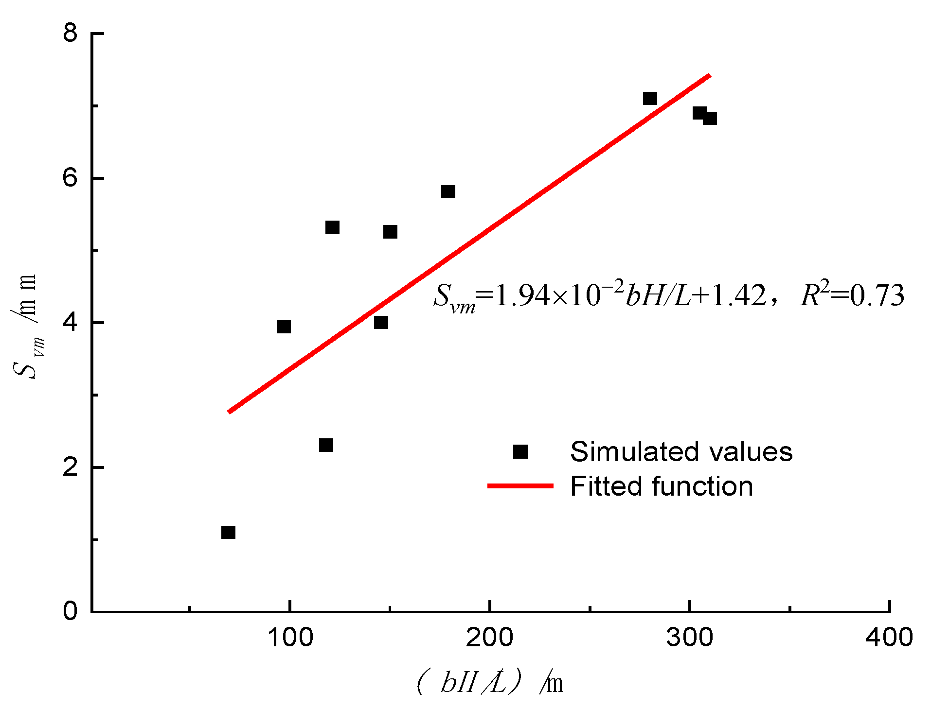
7.2. The Proposed Prediction Formula in This Paper

Liu et al. [23] discussed the k1 values for three types of single strata: soft clay, silty sand, and weathered rock. The larger the k1 value, the greater the influence on the horizontal displacement of the tunnel, but the situation of k1 in composite strata has not been considered yet. Taking the composite strata affected by the fault zone as an example, as shown in Figure 20, this paper establishes a Formula (11) for predicting the maximum horizontal displacement of nearby tunnels under the excavation of the foundation pit in the fault zone influence area, and the k1 value under this geological condition is determined by fitting data.
S h m = 2.07 × 10 2 ( b H / L ) + 2.47
In the formula, Shm is the maximum horizontal displacement of the tunnel, b is the longitudinal width of the foundation pit excavation along the tunnel, H is the depth of foundation pit excavation, L is the horizontal distance from the tunnel axis to the foundation pit, and k1 and k2 are variables related to construction conditions.
As the influence of foundation pit excavation on nearby tunnels is mainly reflected in the horizontal displacement, and the mechanism of vertical displacement is more complex, there are fewer studies on the formula for predicting vertical displacement. As shown in Figure 21, by analyzing the fitting results of the maximum vertical displacement data of the tunnel, it is found that within a certain range of excavation depth (H) of the foundation pit, the maximum vertical displacement of the tunnel is also linearly related to bH/L. Formula (12) for predicting the maximum vertical displacement of nearby tunnels under the excavation of the foundation pit in the fault zone influence area is established, and the k1 value under this geological condition is also determined.
Comparing and analyzing the results, it can be seen that the k1 value in the formula for predicting the maximum horizontal displacement of the tunnel is larger, so the influence of foundation pit excavation on the maximum horizontal displacement of the tunnel is the main factor, while the influence on the maximum vertical displacement is secondary.
Therefore, through this prediction formula, it is possible to obtain the predicted results of the maximum deformation of the tunnel under different conditions, which is of significant importance for engineering planning and design.
S v m = 1.94 × 10 2 ( b H / L ) + 1.42

8. Conclusions

This study investigated the deformation effect of deep excavation on adjacent metro tunnels of the Shenzhen Metro Line 5 Yijing Station and Huangbeiling Station section located in the F1322 fault zone. The deformation impact was studied using theoretical calculations, numerical simulations, and field measurements. The main conclusions are as follows.
(1)
By considering the collaborative deformation effect between piles and excavation sidewall soil under the space effect of excavation, a deformation calculation formula for tunnels has been established.
(2)
The theoretical, numerical, and field results curves are in good agreement. Measures such as “partition excavation, avoiding peripheral loading, increasing isolation piles, and optimizing construction deployment” should be strictly implemented in the construction of foundation pits to reduce the impact on the deformation of adjacent tunnels.
(3)
As the geological parameters increase, the maximum horizontal and vertical displacements of the tunnel exhibit a non-linear decreasing trend, with the rate of decrease continuously increasing. Through sensitivity analysis of the influence of geological parameter variations on the maximum tunnel displacement, it is determined that the elastic modulus is the most sensitive factor, followed by the internal friction angle, with cohesive force having the least impact.
(4)
The fitting of data reveals a good non-linear relationship between the maximum tunnel displacement under composite strata in the fault zone and the parameter (bH/L). Additionally, a prediction formula for the maximum deformation of adjacent tunnels under excavation in this region has been derived.
The application of the deformation calculation formulas and prediction models established in this paper can provide crucial information for the decision-making process of future projects. During the planning and design phase, engineers and planners can utilize these tools to assess the impact of different excavation schemes on the deformation of subway tunnels and select the most suitable approach. Furthermore, these formulas and models can also be employed to formulate construction monitoring plans and risk management strategies, contributing to the safety of subway systems and the sustainable development of cities.

Author Contributions

Conceptualization, Y.N. and F.M.; Methodology, Y.N.; Software, Y.N.; Formal analysis, Y.N.; Investigation, Q.W.; Writing—original draft, Y.N.; Funding acquisition, F.M. All authors have read and agreed to the published version of the manuscript.

Funding

National Natural Science Foundation of China (51474045).

Institutional Review Board Statement

Not applicable.

Informed Consent Statement

Not applicable.

Data Availability Statement

Not applicable.

Conflicts of Interest

The authors declare no conflict of interest.

References

  1. Zhao, X.; Wang, H.X.; Li, Z.W.; Dai, G.L.; Yin, Z.W.; Cao, S.N.; Zhou, J. Numerical Study on the Deformation of Tunnels by Excavation of Foundation Pit Adjacent to the Subway. J. Appl. Sci. 2022, 12, 4752. [Google Scholar] [CrossRef]
  2. Zhou, J.M.; Fan, J.; Zhou, S.B. Study on soil displacement field induced by foundation pit excavation based on shape coefficient. Chin. J. Undergr. Space Eng. 2021, 17, 814–820. [Google Scholar]
  3. Weng, C.X.; Liu, D.S. Influence of foundation pit construction on safety of close subway tunnel. J. Shandong Agric. Univ. 2020, 51, 110–113. [Google Scholar]
  4. Wei, Z.F.; Hu, J.; Xu, T. Integrated Monitoring and Control of Deformation of Metro under Construction effected by the Construction of Foundation Pit. IOP Conf. Ser. Earth Environ. Sci. 2020, 580, 012044. [Google Scholar] [CrossRef]
  5. Zhang, Q.; Wang, Y.F.; Li, J.C.; Zhang, B.; Xu, J. Safety evaluation method of deep foundation pit adjacent to subway tunnel. China Saf. Sci. J. 2021, 31, 95–104. [Google Scholar]
  6. Peng, T.; Peng, Q.S.; Deng, B.; Miao, Y. Investigation and evaluation on construction risk of deep foundation pit near subway line. J. Civ. Eng. Manag. 2020, 37, 113–117. [Google Scholar]
  7. Mu, L.; Lin, J.; Kang, X.; Gu, Z.; Li, S. Intelligent prediction of adjacent tunnel deformation induced by foundation pit excavation based on process response. J. Build. Sci. 2020, 36, 227–232. [Google Scholar]
  8. Moghal, A.A.B.; Abbas, M.F.; Al-Mahbashi, A.M.; Shaker, A.A. Effect of structure anisotropy and compaction method on the swelling behavior of Al-Qatif soil. GEOMATE J. 2016, 11, 2600–2605. [Google Scholar]
  9. Liu, B.; Fan, X.H.; Wang, Y.Y.; Zhang, J.B.; Fan, Z.B. Research progress of influence of foundation pit excavation on adjacent existing subway tunnel. Chin. J. Geotech. Eng. 2021, 43, 253–258. [Google Scholar]
  10. Ding, Z.; Zhang, X.; Liang, F.Y.; Cheng, D.J.; Wang, L.Q. Research and prospect on the influence of soft soil excavation on adjacent existing tunnels. China J. Highw. Transp. 2021, 34, 50–70. [Google Scholar]
  11. Dong, X.; Mei, L.; Yang, S.; He, L. Deformation Response Research of the Existing Subway Tunnel Impacted by Adjacent Foundation Pit Excavation. Adv. Mater. Sci. Eng. 2021, 2021, 5121084. [Google Scholar] [CrossRef]
  12. Yu, Z.T.; Wang, H.Y.; Wang, W.; Ling, D.S.; Zhang, X.D.; Wang, C.; Qu, Y.H. Experimental and numerical investigation on the effects of foundation pit excavation on adjacent tunnels in soft soil. Math. Probl. Eng. 2021, 2021, 5587857. [Google Scholar] [CrossRef]
  13. Zhang, X.; Wei, G.; Jiang, C. The study for longitudinal deformation of adjacent shield tunnel due to foundation pit excavation with consideration of the retaining structure deformation. Symmetry 2020, 12, 2103. [Google Scholar] [CrossRef]
  14. Bian, X.; Hu, H.; Zhao, C.; Ye, J.N.; Chen, Y.M. Protective effect of partition excavations of a large-deep foundation pit on adjacent tunnels in soft soils: A case study. Bull. Eng. Geol. Environ. 2021, 80, 5693–5707. [Google Scholar] [CrossRef]
  15. Zhang, J.; Xie, R.; Zhang, H. Mechanical response analysis of the buried pipeline due to adjacent foundation pit excavation. Tunn. Undergr. Space Technol. 2018, 78, 135–145. [Google Scholar] [CrossRef]
  16. Chen, R.P.; Liu, S.L.; Meng, F.Y.; Ye, J.N.; Zhu, B. Centrifugal model test study on the influence of foundation pit excavation in soft clay stratum on side tunnel. Chin. J. Rock Soil Eng. 2020, 42, 1132–1138. [Google Scholar]
  17. Wang, P.; Ren, J.; Zhai, J.Q. Research on displacement control measures of lateral excavation tunnel in soft soil area of Shanghai. Chin. J. Undergr. Space Eng. 2022, 18, 466–471. [Google Scholar]
  18. Jiang, Z.H.; Zhang, Y.X. Calculation method of influence of foundation pit excavation on longitudinal displacement of adjacent tunnel. Civ. Archit. Environ. Eng. 2013, 35, 7–11+39. [Google Scholar]
  19. Zheng, G.; Wang, Q.; Deng, X.; Du, Y.M. Comparative analysis of deformation modes of different envelope structures on existing tunnel outside pit. Chin. J. Geotech. Eng. 2015, 37, 1181–1194. [Google Scholar]
  20. Cai, Y.; Xing, Y.; Hu, D. Review of sensitivity analysis. J. Beijing Norm. Univ. 2008, 1, 9–16. [Google Scholar]
  21. Wei, G.; Zhao, C.L.; Cai, L.L. Research on the influence mechanism of foundation pit excavation on adjacent existing shield tunnel. Munic. Technol. 2013, 31, 141–146. [Google Scholar]
  22. Wei, G.; Li, J.; Xuan, H.L.; Dong, L.Z.; Xu, Y.Y.; Zhang, S.M. Effect of large deep foundation pit Excavation on Shield tunnel of adjacent Metro. J. Railw. Sci. Eng. 2018, 15, 718–726. [Google Scholar]
  23. Liu, B.; Zhang, D.W.; Li, J.C. Prediction formula of lateral adjacent tunnel deformation caused by foundation pit excavation based on multi-case statistics and its engineering application. Rock Soil Mech. 2022, 43, 501–512. [Google Scholar]
Figure 1. Relative position of foundation pit and subway tunnel.
Sustainability 15 09462 g001
Figure 2. Cross section of foundation pit excavation.
Sustainability 15 09462 g002
Figure 3. The relative relation between foundation pit and subway tunnel.
Sustainability 15 09462 g003
Figure 4. Calculation model of beam on elastic foundation.
Sustainability 15 09462 g004
Figure 5. Comparison of horizontal displacement between centrifugal test and theoretical calculation.
Sustainability 15 09462 g005
Figure 6. Comparison of vertical displacement between centrifugal test and theoretical calculation.
Sustainability 15 09462 g006
Figure 7. Three-dimensional finite element model.
Sustainability 15 09462 g007
Figure 8. Relationship between tunnel supporting structure and tunnel.
Sustainability 15 09462 g008
Figure 9. Comparison of displacement of different tunnels. (a) Horizontal displacement; (b) Vertical displacement.
Sustainability 15 09462 g009
Figure 10. Horizontal displacement of tunnel under different elastic modulus.
Sustainability 15 09462 g010
Figure 11. Vertical displacement of tunnel under different elastic modulus.
Sustainability 15 09462 g011
Figure 12. Horizontal displacement of tunnel under different internal friction angles.
Sustainability 15 09462 g012
Figure 13. Vertical displacement of tunnel under different internal friction angles.
Sustainability 15 09462 g013
Figure 14. Horizontal displacement of tunnel under different cohesion forces.
Sustainability 15 09462 g014
Figure 15. Vertical displacement of tunnel under different cohesion forces.
Sustainability 15 09462 g015
Figure 16. Sensitivity of geological parameters to tunnel maximum displacement.
Sustainability 15 09462 g016
Figure 17. Layout of monitoring points.
Sustainability 15 09462 g017
Figure 18. Comparison of tunnel horizontal displacement.
Sustainability 15 09462 g018
Figure 19. Comparison of tunnel vertical displacement.
Sustainability 15 09462 g019
Figure 20. Prediction curve of tunnel horizontal displacement.
Sustainability 15 09462 g020
Figure 21. Prediction curve of tunnel vertical displacement.
Sustainability 15 09462 g021
Table 1. Calculation parameters of soil layer.
Stratigraphic
(Genetic)
Natural Weight (kN/m3)Tri-Axial Test Secant
Modulus/MPa
Secant
Modulus of
Elasticity/MPa
Unloading Modulus of Elasticity/MPaPoisson’s RatioCohesion (kPa)Internal Friction Angle (°)Permeability
Coefficient (m/d)
Undisturbed soil19.02260.3514155
Soil clay18.52.82.88.40.3325180.1
Angular gravel19.566180.2803625
Sandy clay21.088240.2625225
Fully weathered mixed rock20.01616480.2423280.1
Intensely weathered mixed rock20.52525750.2320320.5
Moderately
weathered mixed rock
21.070702100.22200500.5
Table 2. Section dimensions and physical–mechanical properties of the support structure.
NameMaterialSection
Dimensions/mm
Unit Weight
/(kg/m3)
Elastic Modulus/
GPa
Internal
Friction
Angle/(°)
Poisson’s
Ratio
Retaining pile
(Diaphragm wall)
C30Thickness 880240030260.2
Column pileC30Ø1200240030260.2
Crown beamC301000 × 1200240030260.2
Support beamC301000 × 1200240030260.2
Waist beamC301000 × 1200240030260.2
Table 3. Sensitive factor summary.
IndicatorsVertical Maximum
Displacement Sensitivity
Factor Svn
Horizontal Maximum
Displacement Sensitivity
Factor Shn
Elasticity modulus E0.9360.897
Internal friction angle φ0.6630.615
Cohesion C0.3230.584
Disclaimer/Publisher’s Note: The statements, opinions and data contained in all publications are solely those of the individual author(s) and contributor(s) and not of MDPI and/or the editor(s). MDPI and/or the editor(s) disclaim responsibility for any injury to people or property resulting from any ideas, methods, instructions or products referred to in the content.

