


Ultrasonic–Thermal Regeneration of Spent Powdered Activated Carbon


Abstract
1. Introduction
2. Materials and Methods
2.1. Chemicals and Reagents
2.2. Regeneration Experimental Procedures
- (1)
- The first steps were carried out under isothermal settings (exploring the impact of temperatures between 300 and 700 °C) and dynamical heating conditions (exploring the influence of heating rate between 20 and 40 °C min−1).
- (2)
- Second-step procedures: When prior experiences made it possible to determine the appropriate situations for a higher-adsorption-capacity recovery, the obtained thermal regenerated PAC was then regenerated in an ultrasonic cleaner under an optimal condition that we reported in previous work [26] (with 40 kHz frequency, 0.18 W/mL sonication intensity, 0.1 M NaOH and 50% (v/v) ethyl alcohol mixture as the regeneration solution, and 1 g/L of saturated PAC mass determined to be the optimal desorption conditions).
2.3. Analytical Methods
3. Results and Discussion
3.1. Thermal Desorption Efficiency of Saturated PAC
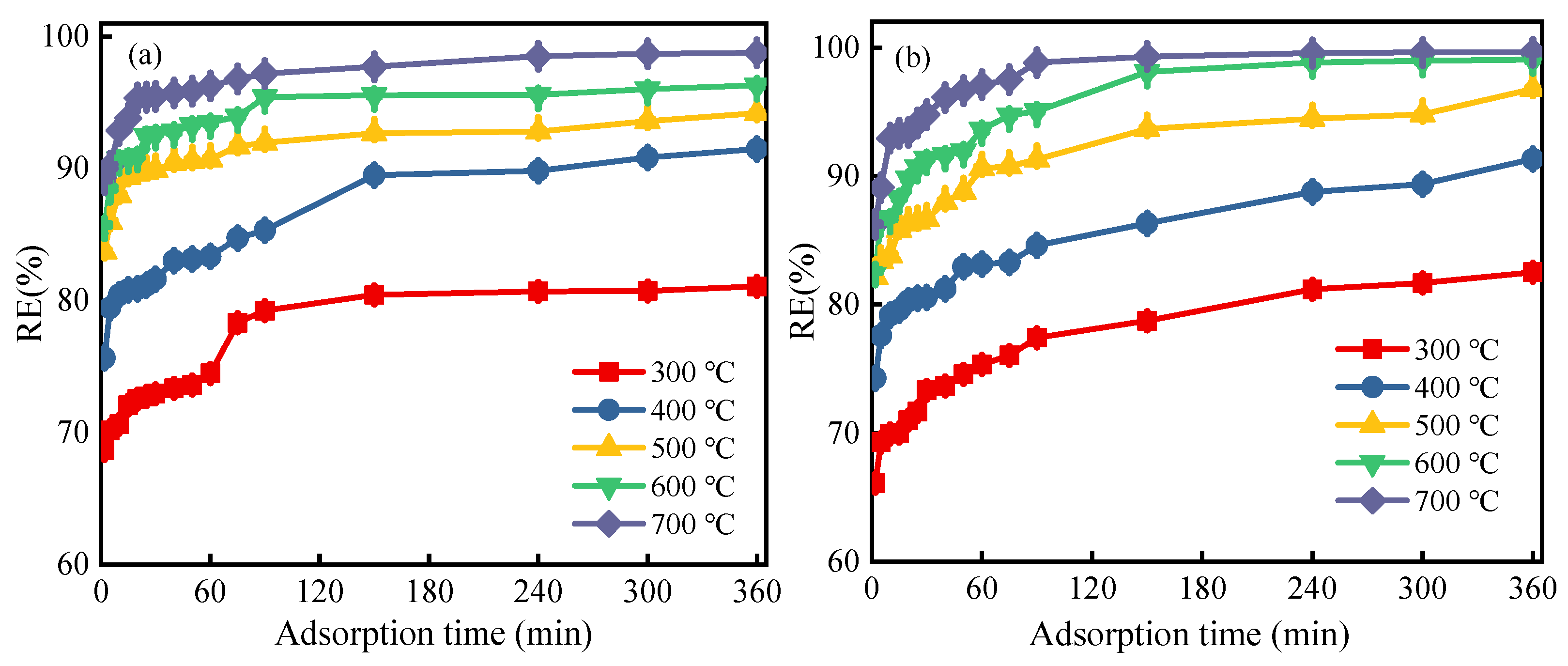
3.1.1. Effect of Regeneration Temperature
3.1.2. Effect of Heating Rate
3.1.3. Effect of Regeneration Time
3.2. Ultrasound-Enhanced Thermal Regeneration Efficiency of Saturated PAC
3.2.1. PAC Regeneration Rate
3.2.2. PAC Weight Loss Percentage
3.3. Characteristics of PACs with Different Regeneration Methods
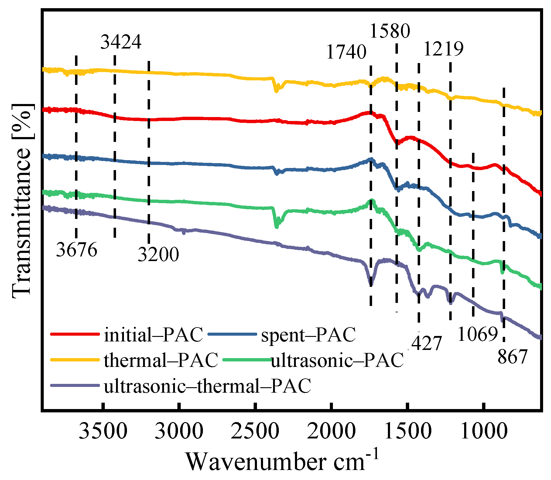
3.3.1. FTIR Analysis
3.3.2. Thermogravimetric Analysis
3.3.3. Characterization of the Various PACs in Different Regeneration Processes
- (1)
- Surface morphology
- (2)
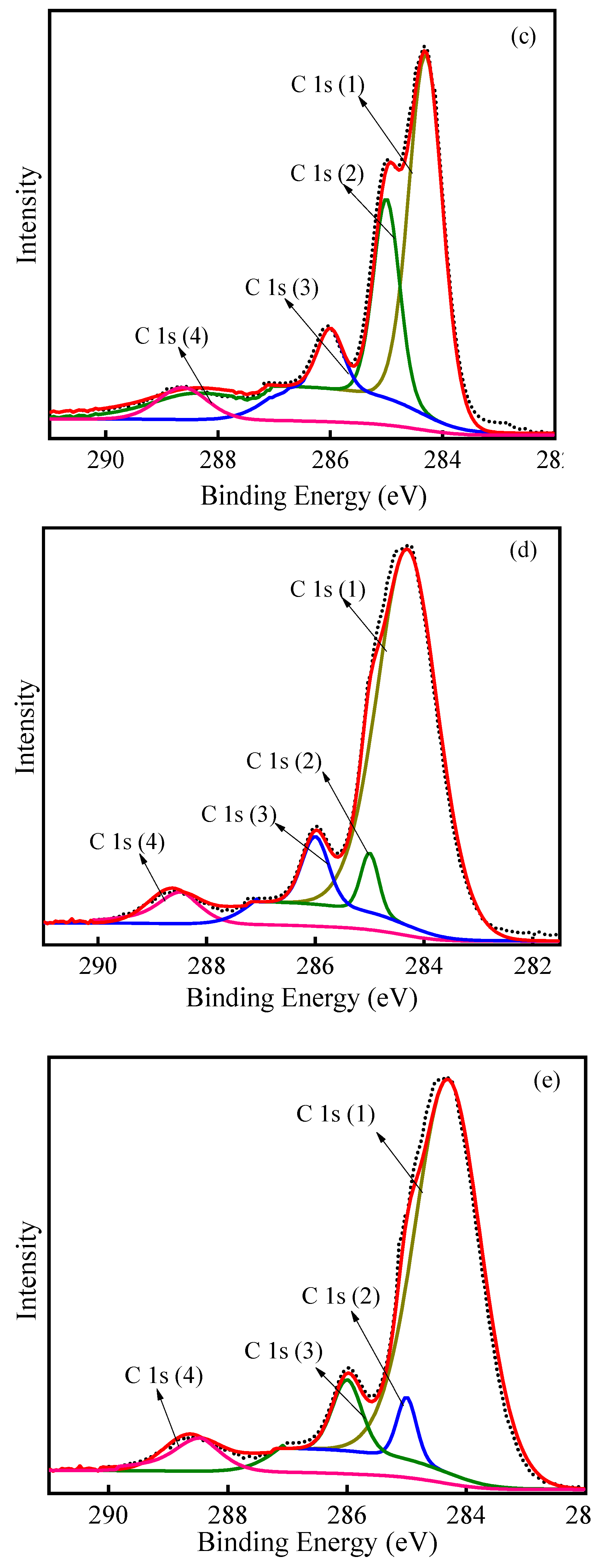
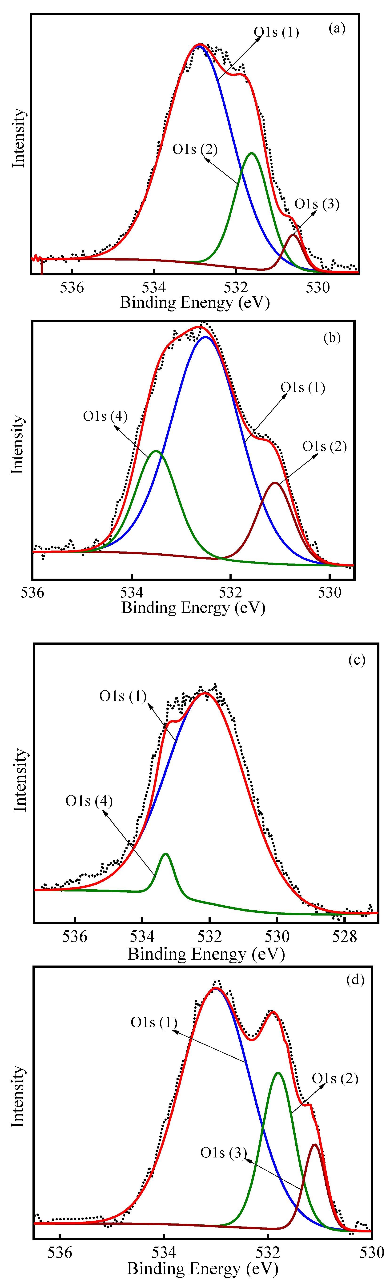
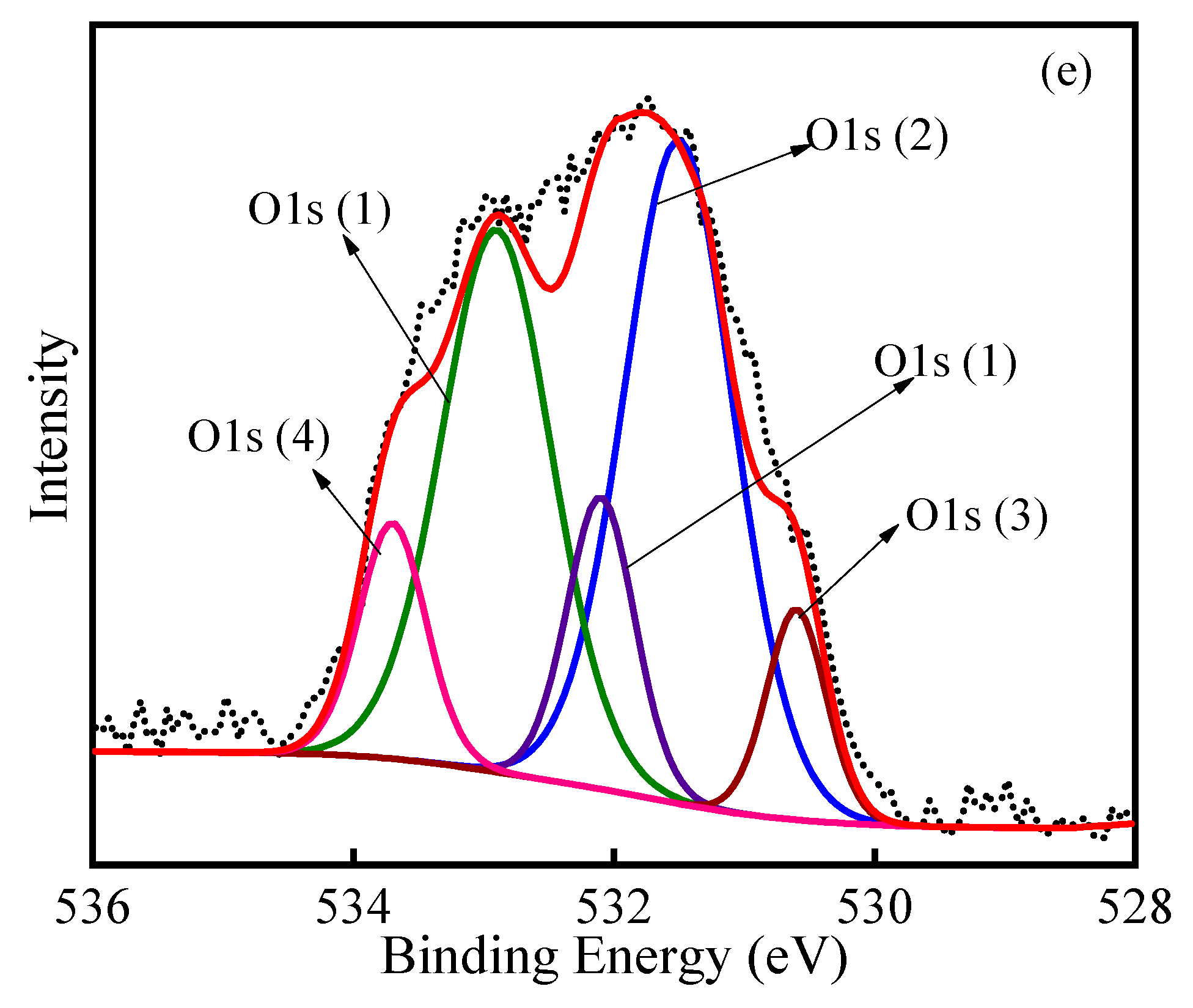
- XPS analysis
- (3)
- XRD analysis
4. Conclusions
- (1)
- Regarding single thermal regeneration processes, the RE and η values all improved with increases in regeneration temperature, heating rate and regeneration time. For practical treatment, we should select relatively reasonable parameters.
- (2)
- Under the optimum conditions for ultrasonic–thermal regeneration of PAC, a RE value of 90.99% and a η value of 5.6% were achieved. The results indicate that ultrasonic–thermal regeneration of PAC might be a practical and energy-efficient technique to reuse exhausted PAC.
- (3)
- The FTIR analysis and XPS results revealed that after ultrasonic–thermal regeneration, a considerable increase in oxygen-containing groups was observed. These oxygen-containing groups may affect the adsorption performance of the regenerated PAC and the subsequent adsorption–regeneration process. The thermogravimetric analysis indicated that ultrasound treatment might weaken the physical interaction force between 4-CP and PAC. Additionally, the XRD analysis demonstrated that the effect of ultrasound and pyrolysis processes changed the crystal structure characteristics of the obtained carbons.
Supplementary Materials
Author Contributions
Funding
Institutional Review Board Statement
Informed Consent Statement
Data Availability Statement
Acknowledgments
Conflicts of Interest
References
- Derylo-Marczewska, A.; Sternik, D.; Swiatkowski, A.; Kusmierek, K.; Gac, W.; Buczek, B. Adsorption of phenol from aqueous and cyclohexane solutions on activated carbons with differentiated surface chemistry. Thermochim. Acta 2022, 715, 179299. [Google Scholar] [CrossRef]
- Wei, X.; Huang, S.; Yang, J.; Liu, P.; Li, X.; Wu, Y.; Wu, S. Adsorption of phenol from aqueous solution on activated carbons prepared from antibiotic mycelial residues and traditional biomass. Fuel Process. Technol. 2023, 242, 107663. [Google Scholar] [CrossRef]
- Lua, A.C. A comparative study of the pore characteristics and phenol adsorption performance of activated carbons prepared from oil-palm shell wastes by steam and combined steam-chemical activation. Green Chem. Eng. 2022. [Google Scholar] [CrossRef]
- Nabais, J.M.V.; Gomes, J.A.; Suhas; Carrott, P.J.M.; Laginhas, C.; Roman, S. Phenol removal onto novel activated carbons made from lignocellulosic precursors: Influence of surface properties. J. Hazard. Mater. 2009, 167, 904–910. [Google Scholar] [CrossRef] [PubMed]
- Fagbohun, E.O.; Wang, Q.; Spessato, L.; Zheng, Y.; Li, W.; Olatoye, A.G.; Cui, Y. Physicochemical regeneration of industrial spent activated carbons using a green activating agent and their adsorption for methyl orange. Surf. Interfaces 2022, 29, 101696. [Google Scholar] [CrossRef]
- Zhang, Q.; Zhang, M.; Li, T.; Du, R.; Yu, G.; Deng, S. FeOCl-confined activated carbon for improving intraparticle Fenton-like oxidation regeneration. J. Hazard. Mater. 2023, 442, 130026. [Google Scholar] [CrossRef]
- Gazigil, L.; Er, E.; Yonar, T. Determination of the optimum conditions for electrochemical regeneration of exhausted activated carbon. Diam. Relat. Mater. 2023, 133, 109741. [Google Scholar] [CrossRef]
- Li, J.; Zhou, W.; Su, Y.; Zhao, Y.; Zhang, W.; Xie, L.; Meng, X.; Gao, J.; Sun, F.; Wang, P.; et al. The enhancement mechanism of the microwave-assisted toluene desorption for activated carbon regeneration based on the constructive interference. J. Clean. Prod. 2022, 378, 134542. [Google Scholar] [CrossRef]
- Xing, X.; Tang, J.; Yao, S.; Chen, H.; Zheng, T.; Wu, J. Electrochemical regeneration of granular activated carbon saturated by p-nitrophenol in BDD anode system. Process. Saf. Environ. 2023, 170, 207–214. [Google Scholar] [CrossRef]
- Ren, M.; Wang, J.; Wang, Z.; Sun, S.; Qiu, J.; Shi, Y.; Wang, Z.-J.; Xie, Y. Activated carbon adsorption coupled with ozonation regeneration for efficient removal of chlorobenzene. J. Environ. Chem. Eng. 2022, 10, 107319. [Google Scholar] [CrossRef]
- Bury, N.A.; Mumford, K.A.; Stevens, G.W. The electro-Fenton regeneration of Granular Activated Carbons: Degradation of organic contaminants and the relationship to the carbon surface. J. Hazard. Mater. 2021, 416, 125792. [Google Scholar] [CrossRef]
- Leong, K.-Y.; Loo, S.-L.; Bashir, M.J.K.; Oh, W.-D.; Rao, P.V.; Lim, J.-W. Bioregeneration of spent activated carbon: Review of key factors and recent mathematical models of kinetics. Chin. J. Chem. Eng. 2018, 26, 893–902. [Google Scholar] [CrossRef]
- Sun, Z.; Liu, C.; Cao, Z.; Chen, W. Study on regeneration effect and mechanism of high-frequency ultrasound on biological activated carbon. Ultrason. Sonochem. 2018, 44, 86–96. [Google Scholar] [CrossRef] [PubMed]
- Chen, X.; Guo, Y.; Zhang, H.; Cheng, F.; Jiao, Z. Coke powder improving the performance of desulfurized activated carbon from the cyclic thermal regeneration. Chem. Eng. J. 2022, 448, 137459. [Google Scholar] [CrossRef]
- Deng, H.; Cai, W.; Zhang, L.; Jia, Y.; Wang, X.; Zong, Q.; Cheng, G.; Hu, X.; Dong, C.; Zhao, Y. First kinetics verification of the useful H2Ogas inhibition on the thermal regeneration of spent activated carbon in flue gas desulfurization. Fuel 2023, 337, 126873. [Google Scholar] [CrossRef]
- Guo, Y.; Du, E. The Effects of Thermal Regeneration Conditions and Inorganic Compounds on the Characteristics of Activated Carbon Used in Power Plant. Energy Procedia 2012, 17, 444–449. [Google Scholar] [CrossRef]
- Márquez, P.; Benítez, A.; Chica, A.F.; Martín, M.A.; Caballero, A. Evaluating the thermal regeneration process of massively generated granular activated carbons for their reuse in wastewater treatments plants. J. Clean. Prod. 2022, 366, 132685. [Google Scholar] [CrossRef]
- Márquez, P.; Benítez, A.; Hidalgo-Carrillo, J.; Urbano, F.J.; Caballero, Á.; Siles, J.A.; Martín, M.A. Simple and eco-friendly thermal regeneration of granular activated carbon from the odour control system of a full-scale WWTP: Study of the process in oxidizing atmosphere. Sep. Purif. Technol. 2021, 255, 117782. [Google Scholar] [CrossRef]
- Tan, L.; Wang, J.; Cai, B.; Wang, C.; Ao, Z.; Wang, S. Nitrogen-rich layered carbon for adsorption of typical volatile organic compounds and low-temperature thermal regeneration. J. Hazard. Mater. 2022, 424 Pt A, 127348. [Google Scholar] [CrossRef]
- Zhou, E.; He, Y.; Ma, X.; Liu, G.; Huang, Y.; Chen, C.; Wang, W. Study of the combination of sulfuric acid treatment and thermal regeneration of spent powdered activated carbons from decolourization process in glucosamine production. Chem. Eng. Process. 2017, 121, 224–231. [Google Scholar] [CrossRef]
- Shen, D.; Labreche, F.; Wu, C.; Fan, G.; Li, T.; Dou, J.; Zhu, J. Ultrasound-assisted adsorption/desorption of jujube peel flavonoids using macroporous resins. Food Chem. 2022, 368, 130800. [Google Scholar] [CrossRef]
- Li, Z.; Xu, K.; Li, X.; Xi, H.; Hua, B.; Li, F. Effect of ultrasound on desorption kinetics of phenol from polymeric resin. Ultrason. Sonochem. 2006, 13, 225–231. [Google Scholar] [CrossRef]
- Low, S.K.; Tan, M.C.; Chin, N.L. Effect of ultrasound pre-treatment on adsorbent in dye adsorption compared with ultrasound simultaneous adsorption. Ultrason. Sonochem. 2018, 48, 64–70. [Google Scholar] [CrossRef]
- Hamdaoui, O.; Naffrechoux, E.; Tifouti, L.; Petrier, C. Effects of ultrasound on adsorption-desorption of p-chlorophenol on granular activated carbon. Ultrason. Sonochem. 2003, 10, 109–114. [Google Scholar] [CrossRef]
- Lim, J.L.; Okada, M. Regeneration of granular activated carbon using ultrasound. Ultrason. Sonochem. 2005, 12, 277–282. [Google Scholar] [CrossRef]
- Zhang, T.T.; Yang, Y.L.; Li, X.; Wang, N.; Zhou, Z.W. Regeneration of 4-chlorophenol from spent powdered activated carbon by ultrasound. Environ. Sci. Pollut. Res. 2019, 26, 9161–9173. [Google Scholar] [CrossRef]
- Guilane, S.; Hamdaoui, O. Ultrasound-assisted regeneration of granular activated carbon saturated by 4-chlorophenol in batch-loop reactor. Desalin. Water Treat. 2016, 57, 17262–17270. [Google Scholar] [CrossRef]
- Nunes, K.G.P.; Sfreddo, L.W.; Rosset, M.; Feris, L.A. Efficiency evaluation of thermal, ultrasound and solvent techniques in activated carbon regeneration. Environ. Technol. 2021, 42, 4189–4200. [Google Scholar] [CrossRef]
- Kang, W.Z.; Li, Y.W. Effect of Ultrasonic Treatment on the Nature of Regeneration of Activated Carbon, 2nd ed.; China Energy Scientist Forum: Xuzhou, China, 2010; pp. 775–778. [Google Scholar]
- Juang, R.S.; Lin, S.H.; Cheng, C.H. Liquid-phase adsorption and desorption of phenol onto activated carbons with ultrasound. Ultrason. Sonochem. 2006, 13, 251–260. [Google Scholar] [CrossRef]
- Liu, C.; Sun, Y.; Wang, D.; Sun, Z.; Chen, M.; Zhou, Z.; Chen, W. Performance and mechanism of low-frequency ultrasound to regenerate the biological activated carbon. Ultrason. Sonochem. 2017, 34, 142–153. [Google Scholar] [CrossRef]
- Shi, C.; Yang, W.; Chen, J.; Sun, X.; Chen, W.; An, H.; Duo, Y.; Pei, M. Application and mechanism of ultrasonic static mixer in heavy oil viscosity reduction. Ultrason. Sonochem. 2017, 37, 648–653. [Google Scholar] [CrossRef]
- Chen, R.; Zheng, D.; Ma, T.; Ding, H.; Su, Y.; Guo, J.; Fu, H. Effects and mechanism of ultrasonic irradiation on solidification microstructure and mechanical properties of binary TiAl alloys. Ultrason. Sonochem. 2017, 38, 120–133. [Google Scholar] [CrossRef]
- Ghaedi, H.; Ayoub, M.; Sufian, S.; Lal, B.; Uemura, Y. Thermal stability and FT-IR analysis of Phosphonium-based deep eutectic solvents with different hydrogen bond donors. J. Mol. Liq. 2017, 242, 395–403. [Google Scholar] [CrossRef]
- Gabruś, E.; Tabero, P.; Aleksandrzak, T. A study of the thermal regeneration of carbon and zeolite adsorbents after adsorption of 1-hexene vapor. Appl. Therm. Eng. 2022, 216, 119065. [Google Scholar] [CrossRef]
- Muncan, J.; Matovic, V.; Nikolic, S.; Askovic, J.; Tsenkova, R. Aquaphotomics approach for monitoring different steps of purification process in water treatment systems. Talanta 2020, 206, 120253. [Google Scholar] [CrossRef]
- Lim, A.; Chew, J.J.; Ismadji, S.; Khaerudini, D.S.; Darsono, N.; Sunarso, J. Kinetic and equilibrium adsorption study of anionic dyes using oil palm trunk-derived activated carbon. Mater. Today Proc. 2022, 64, 1627–1638. [Google Scholar] [CrossRef]
- Pastrana-Martinez, L.M.; Lopez-Ramon, M.V.; Moreno-Castilla, C. Adsorption and thermal desorption of the herbicide fluroxypyr on activated carbon fibers and cloth at different pH values. J. Colloid Interface Sci. 2009, 331, 2–7. [Google Scholar] [CrossRef]
- Li, Q.; Qi, Y.; Gao, C. Chemical regeneration of spent powdered activated carbon used in decolorization of sodium salicylate for the pharmaceutical industry. J. Clean. Prod. 2015, 86, 424–431. [Google Scholar] [CrossRef]
- Estrade-Szwarckopf, H. XPS photoemission in carbonaceous materials: A “defect” peak beside the graphitic asymmetric peak. Carbon 2004, 42, 1713–1721. [Google Scholar] [CrossRef]
- Desimoni, E.; Casella, G.I.; Morone, A.; Salvi, A.M. XPS determination of oxygen-containing functional groups on carbon-fibre surfaces and the cleaning of these surfaces. Surf. Interface Anal. 1990, 15, 627–634. [Google Scholar] [CrossRef]
- González-Elipe, A.R.; Martínez-Alonso, A.; Tascón, J.M.D. XPS characterization of coal surfaces: Study of aerial oxidation of brown coals. Surf. Interface Anal. 1988, 12, 565–571. [Google Scholar] [CrossRef]
- Puziy, A.M.; Poddubnaya, O.I.; Socha, R.P.; Gurgul, J.; Wisniewski, M. XPS and NMR studies of phosphoric acid activated carbons. Carbon 2008, 46, 2113–2123. [Google Scholar] [CrossRef]
- Fang, G.D.; Liu, C.; Gao, J.; Zhou, D.M. New Insights into the Mechanism of the Catalytic Decomposition of Hydrogen Peroxide by Activated Carbon: Implications for Degradation of Diethyl Phthalate. Ind. Eng. Chem. Res. 2014, 53, 19925–19933. [Google Scholar] [CrossRef]
- Kannan, A.G.; Choudhury, N.R.; Dutta, N.K. Synthesis and characterization of methacrylate phospho-silicate hybrid for thin film applications. Polymer 2007, 48, 7078–7086. [Google Scholar] [CrossRef]
- Bhadu, G.R.; Parmar, B.; Patel, P.; Paul, A.; Chaudhari, J.C.; Srivastava, D.N.; Suresh, E. Co@N-doped carbon nanomaterial derived by simple pyrolysis of mixed-ligand MOF as an active and stable oxygen evolution electrocatalyst. Appl. Surf. Sci. 2020, 529, 147081. [Google Scholar] [CrossRef]
- Ni, J.; Huang, Y.; Gao, L. A high-performance hard carbon for Li-ion batteries and supercapacitors application. J. Power Source 2013, 223, 306–311. [Google Scholar] [CrossRef]
- Xu, S.; Niu, M.; Zhao, G.; Ming, S.; Li, X.; Zhu, Q.; Ding, L.-X.; Kim, M.; Alothman, A.A.; Mushab, M.S.S.; et al. Size control and electronic manipulation of Ru catalyst over B, N co-doped carbon network for high-performance hydrogen evolution reaction. Nano Res. 2022, 16, 6212–6219. [Google Scholar] [CrossRef]


Disclaimer/Publisher’s Note: The statements, opinions and data contained in all publications are solely those of the individual author(s) and contributor(s) and not of MDPI and/or the editor(s). MDPI and/or the editor(s) disclaim responsibility for any injury to people or property resulting from any ideas, methods, instructions or products referred to in the content. |
© 2023 by the authors. Licensee MDPI, Basel, Switzerland. This article is an open access article distributed under the terms and conditions of the Creative Commons Attribution (CC BY) license (https://creativecommons.org/licenses/by/4.0/).
Share and Cite
Zhang, T.; Yang, Y.; Li, X.; Zhou, Z.; Wei, B. Ultrasonic–Thermal Regeneration of Spent Powdered Activated Carbon. Sustainability 2023, 15, 9060. https://doi.org/10.3390/su15119060
Zhang T, Yang Y, Li X, Zhou Z, Wei B. Ultrasonic–Thermal Regeneration of Spent Powdered Activated Carbon. Sustainability. 2023; 15(11):9060. https://doi.org/10.3390/su15119060
Chicago/Turabian StyleZhang, Tingting, Yanling Yang, Xing Li, Zhiwei Zhou, and Bigui Wei. 2023. "Ultrasonic–Thermal Regeneration of Spent Powdered Activated Carbon" Sustainability 15, no. 11: 9060. https://doi.org/10.3390/su15119060
APA StyleZhang, T., Yang, Y., Li, X., Zhou, Z., & Wei, B. (2023). Ultrasonic–Thermal Regeneration of Spent Powdered Activated Carbon. Sustainability, 15(11), 9060. https://doi.org/10.3390/su15119060