Article

Adaptive Stability Control Based on Sliding Model Control for BEVs Driven by In-Wheel Motors

1
College of Mechanical & Electronic Engineering, Dalian Minzu University, Dalian 116600, China
2
School of Automotive Engineering, Dalian University of Technology, Dalian 116024, China
3
Ningbo Institute, Dalian University of Technology, Ningbo 315016, China
*
Author to whom correspondence should be addressed.
Sustainability 2023, 15(11), 8660; https://doi.org/10.3390/su15118660
Submission received: 13 April 2023 / Revised: 25 May 2023 / Accepted: 25 May 2023 / Published: 26 May 2023

Abstract

:
High-speed and complex road conditions make it easy for vehicles to reach limit conditions, increasing the risk of instability. Consequently, there is an urgent need to solve the problem of vehicle stability and safety. In this paper, adaptive stability control is studied in BEVs driven by in-wheel motors. Based on the sliding model algorithm, a joint weighting control of the yaw rate and sideslip angle is carried out, and a weight coefficient is designed using a fuzzy algorithm to realize adaptive direct yaw moment control. Next, optimal torque distribution is designed with the minimum sum of four tire load rates as the optimization objective. Then, combined with the road adhesion coefficient and the maximum motor torque constraint, the torque distribution problem is transformed into a functionally optimal solution problem with constraints. The simulation results show that the direct yaw moment controller based on the adaptive sliding mode algorithm has a good control effect on the yaw rate and sideslip angle, and it can effectively improve vehicle adaptive stability control. In the optimal torque distributor based on road surface recognition, the estimated error of road adhesion is within 10%, and has a greater margin to deal with vehicle instability, which can effectively improve vehicle adaptive stability control.

1. Introduction

The dual pressure from the fuel crisis and the need to increase environmental protection has promoted the rapid development of new energy vehicles, especially the development of electric vehicles driven by in-wheel motors. Electric vehicles driven by in-wheel motors have the characteristics of independent controllable torque output, fast response speed and free distribution. These characteristics provide convenient conditions and development potential for research on automotive stability control [1].
As road conditions and the surrounding environment are changeable, it is hard to make accurate predictions regarding stability. In good road conditions, a vehicle can operate normally according to the driver’s intent. However, under poor road conditions, it is easy for the vehicle to reach limit conditions. If the vehicle cannot run according to the driver’s intent, this will lead to a deviation between the vehicle’s path and the path expected by the driver, thus making the vehicle prone to sideslips and even tail-throwing. With increases in vehicle speed and constant changes in traffic flow, the probability of traffic accidents increases. At the same time, road conditions are becoming more complex, increasing the probability of vehicle instability [2]. Meanwhile, ensuring time and space synchronization between different sensors is essential for vehicle control signal input, as has been found in the literature [3]. This will also present a challenge for the stability control of the vehicle. Therefore, adaptive stability control for BEVs driven by in-wheel motors has become a research focus.
Based on the characteristics of in-wheel motor drive electric vehicles, widely used stability control methods are active front steering, direct yaw moment control (DYC) and some integrated control systems [4]. Active front steering can improve cornering stability by introducing an additional steering angle in accordance with the vehicle state [5]. DYC can exert an external yaw moment to control the lateral motion of vehicles to achieve good stability in both linear and nonlinear working areas of tires [6]. For in-wheel motor drive electric vehicles, the main problems of DYC arise from how to calculate the optimal yaw moment and generate the desired moment by allocating the torque of each wheel. Some systems integrate active front steering and DYC to realize stability control [7]. For example, Wu et al. [8] proposed a divisional adaptive coordination model predictive control (MPC) controller by adjusting the weights between the active front steering and DYC according to the stability margin. However, when the vehicle is in an unstable state, the tires are also in a nonlinear working area. Due to the limited adhesion, the tires’ lateral force is in a saturated state. It is impossible to change the vehicle state through steering, and the electronic stability control system based on steering cannot effectively improve the vehicle handling and stability [9]. Therefore, this paper mainly concentrates on DYC to improve the handling stability and safety of in-wheel motor drive electric vehicles.
DYC determines the vehicle stability state according to information presented by sensors or estimated methods. Different control algorithms and strategies are utilized to track and control the vehicle reference state to obtain the designed additional yaw moment required for stability control. Then, the wheel torque control allocator is designed to generate the designed yaw moment. DYC can be conducted through asymmetric wheel braking, which has been employed in many traditional centralized-driven vehicles, or through driving, which is unique for in-wheel motor drive electric vehicles [10]. Currently, a large number of control theories, such as proportional integral differential (PID), linear quadratic regulator, sliding mode control (SMC) and MPC have been applied to the study of DYC. Ahmed et al. [11] proposed a yaw moment control algorithm based on a PID controller to adjust the yaw rate of the vehicle to the desired value. Jung et al. [12] presented a linear quadratic regulator-based controller for an all-wheel drive electric vehicle by considering changeable dynamic behavior. Majidi et al. [13] obtained direct yaw moment for electric vehicles by using adaptive SMC, and accomplished a proper distribution of longitudinal force among four individual wheels, in turn, enhancing the yaw stability of the vehicle. Liu et al. [14] proposed a multi-level coordinated yaw stability control method based on sliding MPC, which helps to improve the maneuverability and handling stability of in-wheel motor drive electric vehicles under extreme conditions. Li et al. [15] propose a multi-objective velocity-dependent controller for a four-wheel independently actuated electric vehicles to guarantee lateral stability under longitudinal velocity uncertainty. However, the robustness of PID control and the linear quadratic regulator is poor, and the adaptive ability and control effect under complex conditions are not good. At the same time, MPC permits iterative optimization solutions with accurate models. When the model accuracy is low, prediction is inaccurate. Considering the strong nonlinearity and parameter uncertainty of in-wheel motor drive electric vehicles under extreme working conditions, SMC has a simple structure, fast solving efficiency and good robustness under external disturbances, modeling errors and parameter ingestion. Therefore, this paper utilizes the SMC algorithm to design a direct yaw moment control strategy.
SMC is widely used in complex nonlinear systems because of its insensitivity and strong robustness against external disturbances and uncertainties. For example, Liu et al. [16] designed an additional yaw moment controller based on SMC by taking yaw angle, yaw rate and lateral displacement as the control variables. Qin et al. [17] designed a sliding mode controller considering suspension load transfer and dynamic characteristics to control the output torque of each in-wheel motor and improve vehicle lateral stability. However, the use of fixed weights in the design of the sliding mode surface makes it difficult to ensure adaptability under different working conditions. Asiabar et al. [18] proposed an adaptive sliding mode controller to achieve the corrective yaw moment, generated through direct control of the driving and braking torques of four in-wheel motors to improve vehicle handling stability and maintain yaw stability. Yang et al. [19] presented a yaw moment controller based on SMC and distributed the driving/braking torque for each wheel. The relevant research provides some reference points for the development of stability control for electric vehicles with four in-wheel-motors. However, the uncertainty of road conditions was not considered in the torque distribution, and the requirements for vehicle adaptability were thus not satisfied. With the complexity of the vehicle driving environment and working conditions, the nonlinear impact of vehicle control will lead to the degradation of tracking performance, which is the key problem to be solved by the currently designed controllers. In this paper, an adaptive sliding mode controller is designed that can improve the adaptive performance of the controller by intelligently adjusting the sliding mode surface coefficient through fuzzy control strategy. The purpose of the work is to improve the adaptive performance of the controller by intelligently adjusting the sliding mode surface coefficient through fuzzy control strategy. Some hypotheses are based on the complex road conditions that will result in instability for BEVs.
Based on the above research, the main contributions of this paper include the following: (1) an adaptive stability hierarchical control framework for an in-wheel motor drive electric vehicle is proposed, including an upper motion tracking layer to generate the additional yaw moment, and a lower optimization torque distribution layer to determine the output torque of each in-wheel motor; and (2) the optimal yaw torque is determined by an adaptive sliding mode controller, combined with the road adhesion coefficient and the maximum motor torque constraint, the road adhesion coefficient is intelligently estimated by a fuzzy strategy, and finally the torque distribution problem is transformed into a functionally optimal solution problem with constraints.
This paper is organized as follows: Section 2 builds a model of an in-wheel motor drive electric vehicle. The adaptive stability control based on a sliding model control is presented in detail in Section 3. A simulation verification platform is given in Section 4 to verify the designed controller. Section 5 concludes the paper.

2. Vehicle Modeling

2.1. Vehicle Dynamic Model

Vehicle dynamic modeling is of great importance for vehicle dynamic control. Vehicle stability can be analyzed systematically by establishing a linear two-degrees-of-freedom model. The two-degrees-of-freedom vehicle model ignores the influence of suspension and considers its lateral and yaw motions, which can reflect important dynamic characteristics for stability analyzation. The dynamic motion can be expressed as follows:
m v x ( β ˙ + ω r ) = k f ( β + a ω r v x δ ) + k r ( β b ω r v x )
I z ω ˙ r = a k f ( β + a ω r v x δ ) b k r ( β b ω r v x )
where m is the vehicle mass, vx is the vehicle longitudinal speed, β is the vehicle sideslip angle at the center of gravity, ωr is the yaw rate, kf and kr represent the cornering stiffness of the front and rear tires, respectively, a and b represent the distance from the front and rear axle to the center of gravity, respectively, δ represents the front wheel angle and IZ represents the moment of inertia of the vehicle about the Z axis.
Vehicle dynamic control has always been an important branch of research in the field of vehicles [20]. The vehicle kinematic and dynamic states, such as sideslip angle, can be estimated based on a consensus Kalman filter, improved vehicle localization using on-board sensors and vehicle lateral velocity. Considering the influence of road conditions and adhesion on the vehicle state, the range of yaw rate and sideslip angle should be given. Therefore, the desired vehicle yaw rate and sideslip angle can be calculated according to the following formula [21]:
ω rd = min v x ( 1 + K c v x 2 ) L δ , 0.85 μ g v x sgn ( δ ) β d = min ( b ( 1 + K c v x 2 ) L + a m v x 2 ( 1 + K c v x 2 ) L 2 ) δ , arctan ( 0.02 μ g ) sgn δ
where ωrd represents the desired yaw rate, βd represents the desired sideslip angle of the vehicle, L represents the vehicle wheelbase, μ represents the road adhesion coefficient, g represents the acceleration of gravity, sgn() is the sign function and Kc represents the stability factor, which can be calculated as follows:
K c = m L a k r b k f

2.2. Driver Model

The driver model generally includes two parts: steering wheel input and speed control. The steering wheel input can be closed loop or open loop. The closed-loop steering wheel input determines the output steering angle according to the expected trajectory. The open-loop input determines the output steering angle directly. Speed control is conducted based on a proportional integral algorithm to determine the total driving torque Treq according to the deviation between the actual vehicle speed and the driver’s expected speed. This can be expressed as follows:
T req = K speed k p ( u u d ) + k i ( u u d ) d t
where u represents the actual vehicle speed, ud represents the driver’s expected speed, Kspeed represents the speed coefficient, and kp and ki represent the proportion and integration coefficient, respectively.

2.3. In-Wheel Motor Model

The in-wheel motor model is established based on the external characteristic curve of the motor, and its transfer function relationship is as follows:
G ( s ) = 1 1 + 2 ζ s + 2 ζ 2 s 2
where ζ is the motor characteristic coefficient, which is related to the motor type.

2.4. Battery Model

Currently, models of battery include Rint, Thevenin, PNGV and GNL, etc. [22]. The Rint type has characteristics of a simple structure and strong applicability, while the charging and discharging process of the battery system is a complex electrochemical reaction process. The focus of this work is on vehicle stability control, without involving the study of battery electrification and the reaction process. Therefore, the Rint model was selected as the battery model, and its main data parameters are shown in Table 1.
The state equation of the battery is:
P 0 ( t ) = U 0 S O C ( t ) I ( t ) I 2 ( t ) R 0 n g
where P0(t) is the total output power, U0 is the open circuit voltage, P0(t) is the current of each cell, R0 is the internal resistance of each cell and ng is the number of battery cells.

2.5. Tire Model

The Pacejka magic formula is used as the tire model to calculate the longitudinal force, lateral force and aligning torque of the tire. The magic formula uses the combination formula of trigonometric function to fit the tire test data, so as to achieve a more complete expression of the relationship between the tire forces and the working conditions. The general expression of the tire model is:
Y ( x ) = D sin C arctan B x E B x arctan B x
where Y(x) represents the lateral force (longitudinal force or aligning torque) of the tire, the independent variable x can be the slip angle or longitudinal slip rate of the tire, and the coefficients B, C, D and E can be calculated by the vertical load and camber of the tire.
To show the dynamic performance of the in-wheel motor drive electric vehicle, Matlab/Simulink (latest vR2023a) and Carsim (latest v2023.0) are utilized to establish the co-simulation verification platform. The vehicle parameters are shown in Table 2.

3. Adaptive Stability Control

Figure 1 illustrates a layered control framework for the adaptive stability of an in-wheel motor-driven electric vehicle, which mainly consists of a motion tracking layer and an optimized torque distribution layer. In the motion tracking layer, a direct yaw torque controller is designed to achieve the purpose of tracking the desired state through real-time feedback of the vehicle state and to determine the additional yaw moment. In the optimized torque distribution layer, a torque distribution controller is designed to reasonably determine the output torque of each in-wheel motor to generate an additional yaw moment to achieve stable vehicle driving.

3.1. Stability Analysis and Judgement

Vehicle yaw rate and sideslip angle are key factors in analyzing the stability of a vehicle [23]. Yaw rate reflects the degree of rotation of the vehicle around the central axis and is used to describe the stability of the vehicle in the yaw direction, and the sideslip angle is the angle between the velocity longitudinal direction and the traveling direction of the vehicle center of gravity. These factors can reflect vehicle stability well [24]. Therefore, this paper uses the combination of yaw rate and sideslip angle as the stability variables to evaluate vehicle stability.
The yaw rate error between the real yaw rate and the desired yaw rate obtained from the nonlinear two-degrees-of-freedom vehicle model is used to judge the vehicle running state. When the error exceeds a preset value, the vehicle is in an unstable state. Otherwise, the vehicle is in a stable state. The yaw rate judgement is as follows [25]:
ω r ω rd ξ ω rd
where ξ represents the stability judgement coefficient of the yaw rate.
Vehicle stability can be determined mainly based on phase plane analysis. According to phase plane analysis theory, the phase plane β β ˙ can be utilized to judge the vehicle stability [26]:
B 1 β ˙ B 2 β 1
where B1 and B2 represent the boundary stability judgement coefficients.

3.2. Direct Yaw Moment Controller Based on Adaptive Sliding Mode

The direct yaw moment controller is designed based on SMC to achieve combined control of the yaw rate and sideslip angle of the vehicle. The output of the controller is the additional yaw moment, which can improve the vehicle stability.
The selection of the sliding surface is key to the SMC system, which affects its dynamic quality. To realize adaptive stability control of the vehicle, the sliding surface is designed as follows:
s = k s ( ω r ω rd ) + ( 1 k s ) ( β β d )
where ks is the weight coefficient of the combined control of the yaw rate and sideslip angle of the vehicle.
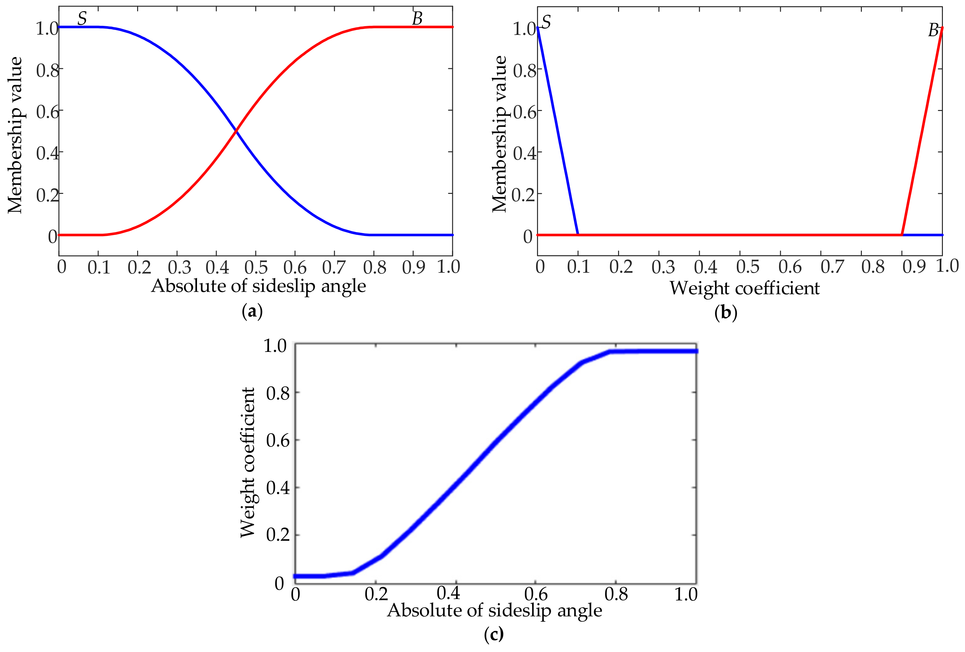
Due to differences in road conditions, different degrees of instability will occur. Therefore, it is necessary to design the sliding mode surface with different weights to achieve the control effect of the desired yaw rate and sideslip angle and to achieve the adaptive vehicle stability control. When the actual sideslip angle is lower than β1 (the lower limit value of the sideslip angle), the vehicle has a small degree of instability. In this condition, the yaw rate needs to be controlled and ks is set to 1. When the actual sideslip angle is between β1 and β2 (the upper limit value of the sideslip angle), the vehicle is in a moderately unstable state. Then, the yaw rate and the sideslip angle need to be controlled simultaneously and ks is between 0 and 1. When the actual sideslip angle is larger than β2, the vehicle will seriously lose stability and will deviate from its expected track, so the sideslip angle needs to be controlled and ks is set to 0.
This paper uses a fuzzy algorithm to design the weight coefficient of the combined control of the yaw rate and sideslip angle of the vehicle. The input is the absolute value of the sideslip angle β , while output is the weight coefficient ks. Both the input and output variables are set to be in the range of 0 and 1. The fuzzy languages for the input and output variable are small (S) and big (B). The scale coefficient of the input is 10 and that of the output is 1. The membership function of input and output and its relation are shown in Figure 2.
The derivative of variable sliding surface is as follows:
s ˙ = k s ( ω ˙ r ω ˙ rd ) + ( 1 k s ) ( β ˙ β ˙ d )
We can obtain:
ω ˙ r = s ˙ - ( 1 k s ) ( β ˙ β ˙ d ) k s + ω ˙ rd
We select the constant velocity approach law as follows:
s ˙ = ε sgn ( s ) , ε > 0
where ε is the approach velocity, Meq is the equivalent item and Ms is the switching item.
Then the control law is:
Δ M = M eq + M s
where △M is the additional yaw moment, and Meq and Ms are the equivalent and switching control item, respectively.
To establish the two-degrees-of-freedom vehicle model that considers the additional yaw moment we use:
m v x ( β ˙ + ω r ) = k f ( β + a ω r v x δ ) + k r ( β b ω r v x ) I z ω ˙ r = a k f ( β + a ω r v x δ ) b k r ( β b ω r v x ) + Δ M
According to (12) and (16), the additional yaw moment is:
Δ M = I z ω ˙ r a k f ( β + a ω r v x δ ) + b k r ( β b ω r v x ) = I z s ˙ - ( 1 k s ) ( β ˙ β ˙ d ) k s + ω ˙ rd a k f ( β + a ω r v x δ ) + b k r ( β b ω r v x )
According to the Lyapunov function, the stability analysis of the sliding variable structure controller is proved as follows:
s s ˙ = s ε sgn ( s ) = ε s 0

3.3. Torque Distribution Controller Based on Road Adhesion Coefficient Recognition

Figure 3 shows a torque distributor considering multiple constraints. The upper control layer decides the optimal yaw moment to be sent to the optimal torque distributor by an adaptive sliding mode controller, and combines the road adhesion coefficient and the maximum motor torque constraint, where the road adhesion coefficient is intelligently estimated by a fuzzy strategy for its peak value, and finally transforms the torque distribution problem into a functionally optimal solution problem with constraints.
The upper control layer decides the optimal yaw moment to be sent to the optimal torque distributor by an adaptive sliding mode controller, and combines the road adhesion coefficient and the maximum motor torque constraint, where the road adhesion coefficient is intelligently estimated by a fuzzy strategy for its peak value, and finally transforms the torque distribution problem into a functionally optimal solution problem with constraints.
The utilization rate reflects the adhesion utilization of tires and is an evaluation index for vehicle stability margin [27]. The utilization rate of tires refers to the numerical value of each tire’s utilization of ground adhesion. When its value approaches 100%, it indicates that the tire will reach the limit of road adhesion. At this time, the tire is in a saturated state, and the vehicle is at risk of losing stability. When the tire utilization rate is small, the tire adhesion margin is larger and the vehicle will be in a stable state. On the contrary, when the tire utilization rate is large, the tire adhesion margin is small and the vehicle may become unstable. Therefore, the minimum sum of the utilization rate of each tire should be taken as the objective of the optimal torque distribution. The function is as follows:
min J = min i = 1 4 F x i 2 + F y i 2 ( μ F z i ) 2
where J represents the objective function, Fxi, Fyi and Fzi represent the longitudinal force, lateral force and vertical force of the ith tire, respectively, i = 1, 2, 3, 4, and μ is the road adhesion coefficient.
According to the tire adhesion ellipse, the forces acting on the tire are divided into lateral and longitudinal forces, which do not exist separately. When one force changes, the other force is also affected. There is a coupling relationship between the two forces. Due to the constraint of the adhesion ellipse, they also need to satisfy the following function:
F x i 2 ( μ F z i ) 2 + F y i 2 ( μ F z i ) 2 1
When distributing the torque, the objective function should consider whether the torque of each wheel can meet the requirements of the additional yaw moment required for maintaining vehicle stability. In addition, the total driving torque demand for vehicle speed should also be considered. Due to the physical properties of the in-wheel motor, the torque distributed by each motor cannot exceed the maximum torque of the in-wheel motor. The tire is constrained by the adhesion ellipse, and the driving force generated must also be within the maximum adhesion of the road. Based on the above constraints, the additional yaw moment, the total driving torque, the maximum output torque of the in-wheel motor and the road adhesion condition constraints should be considered simultaneously as follows:
T d = ( T 1 + T 2 ) cos δ + ( T 3 + T 4 ) Δ M = L 2 R ( T 2 T 1 ) cos δ + ( T 4 T 3 ) T max T i T max F x i 2 + F y i 2 μ F z i
where Td represents the total driving torque, Ti represents the driving torque of the ith wheel, Tmax represents the maximum torque of the in-wheel motor and R represents the rolling radius of the tire.
Most torque distribution algorithms assume a fixed value for the road adhesion coefficient, which cannot reflect the real state of the road. According to the estimated peak road adhesion, the maximum driving force can be determined to prevent the power generated by the vehicle from exceeding the maximum tire force [28]. Therefore, this paper designs a road adhesion coefficient estimator to realize a real-time estimation of road adhesion and improve vehicle stability and safety. Based on the tire–road mathematical model proposed by Burckhardt and its modifications [29,30], the road adhesion coefficient estimator is designed based on a fuzzy algorithm according to the adhesion coefficient and slip rate curve of a standard road.
The slip rate of each wheel is calculated as follows:
s i = ω i R v i ω i R
where si is the slip rate of the ith wheel; ωi is the angular velocity of the ith wheel; and vi is the longitudinal velocity of the ith wheel.
Reference roads usually include six types of conditions: ice, snow, wet pebble, wet asphalt, dry cement and dry asphalt [31]. However, the difference between the peak adhesion coefficient of wet pebble and wet asphalt is large, which is not conducive to the recognition of the entire road. Therefore, this paper adds two kinds of reference roads between wet pebble and wet asphalt, namely road 1 and road 2. Moreover, considering that the peak adhesion coefficient of dry asphalt is similar to that of dry cement, Road 3 was used to adjust and replace dry asphalt to improve the accuracy of pavement adhesion estimation. The peak adhesion coefficient of each reference road is shown in Table 3.
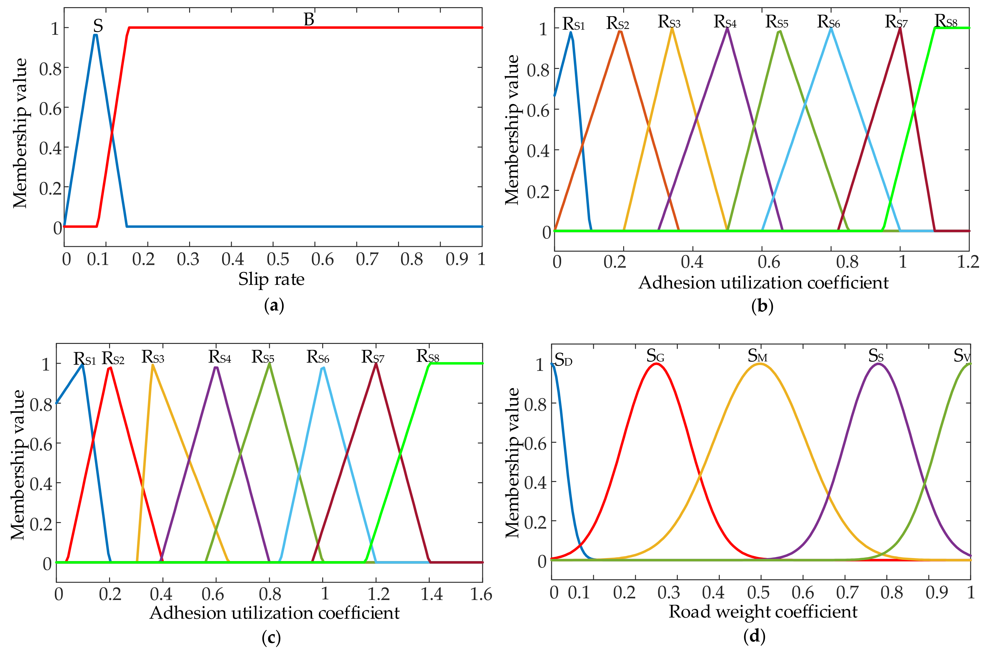
A fuzzy algorithm is used to determine the weight coefficient of each reference road. The slip rate of each wheel and the adhesion utilization coefficient are taken as the input and the road weight coefficient of the reference road is taken as the output. The domain of the slip rate is [0, 1]. The fuzzy subset of the slip rate is S and B (representing small and large slip rate, respectively). When the slip rate is small, the domain of adhesion utilization coefficient is [0, 1.2]. When the slip rate is large, the domain of the adhesion utilization coefficient is [0, 1.6]. The domain of the road weight coefficient of the reference road is [0, 1]. The fuzzy subset of the adhesion utilization coefficient is {RS1, RS2, RS3, RS4, RS5, RS6, RS7, RS8} (representing ice, snow, wet pebble, road 1, road 2, wet asphalt, dry cement and road 3, respectively). The fuzzy subset of the road weight coefficient is {SD, SG, SM, SS, SV} (representing not similar at all, not similar, generally similar, similar and completely similar). The membership function of input and output is shown in Figure 4.
According to the experience of experts, the logical reasoning rules of the road coefficient recognition are formulated as shown in Table 4.
The road weight coefficients of the eight reference roads determined by the fuzzy control rules can be used to obtain the estimated peak adhesion coefficient of the current road as follows:
μ est = i = 1 8 m i μ i i = 1 8 m i
where mi is the road weight coefficient of ice, snow, wet pebble, road 1, road 2, wet asphalt, dry cement and road 3, μi is the peak adhesion coefficient of ice, snow, wet pebble, road 1, road 2, wet asphalt, dry cement and road 3, and μest is the estimated peak adhesion coefficient of the current road.
Based on the results of the road coefficient identification, the torque assignment problem can be converted into a quadratic programming problem with constraints, which can be solved using the effective set method, and then the actual output torque of each wheel can be achieved. In addition, the basic idea of the effective set method is to treat the inequality constraint as an equation constraint in each iteration and ignore other non-functional inequality constraints [32,33].

4. Simulation Verification

The performance of the proposed direct yaw moment controller based on the adaptive sliding mode algorithm and the torque distribution controller based on road coefficient recognition are tested utilizing the established co-simulation platform.

4.1. Verification of Direct Yaw Moment Controller

To verify the stability and adaptability of the direct yaw moment controller, three controllers with different weight coefficients of the combined control of the yaw rate and sideslip angle of the vehicle are used, in which the weight coefficient ks is 0.5, 1 and is changing according to the vehicle state, respectively.
To verify the effect of stability control when the vehicle rapidly changes lanes on the wet road with low adhesion at medium and high speed, the double-lane-changing condition is adopted for testing. The longitudinal vehicle speed is set to 80 km/h and the road adhesion coefficient is 0.2. The simulation results of the condition are shown in Figure 5.
Figure 5a shows the trajectory of the double-lane-changing condition information. Figure 5b presents the change in the weight coefficient of the sliding mode surface under this condition. The weight coefficient reaches a maximum value of 0.14 at about 6 s and then fluctuates slightly. Figure 5c,d shows the vehicle yaw rate and sideslip angle under three direct yaw moment controllers, in which the weight coefficient ks is 0.5, 1 and is changing, respectively. The yaw rate varies within the range of ±0.1 rad/s, and its extreme values are 0.0763 rad/s, 0.0776 rad/s and 0.0770 rad/s, respectively. The vehicle sideslip angle varies within the range of ±0.02 rad, and its extreme values are 0.0075 rad, 0.0155 rad and 0.0132 rad, respectively. Direct yaw moment controllers with different weight coefficients achieve different control effects. When the weight coefficient is 0.5, the extreme value of the yaw rate and sideslip angle is obviously small. However, there is a serious delay phenomenon. When the weight coefficient is 1 and the weight coefficient changes, the extreme value of the yaw rate and sideslip angle is high, but the response is fast. It can be seen from the phase plane simulation results in Figure 5e that the area enclosed by the phase plane of the sideslip angle is smaller when the weight coefficient is 0.5 than that of the controller when its weight coefficient is 1 and is changing. That is, the change in the sideslip angle is more convergent and the control effect is better.
To test the effect of vehicle stability control on emergency obstacle avoidance under high-speed conditions, the fishhook condition is used to simulate the emergency obstacle avoidance under extreme conditions. The longitudinal speed of the vehicle is 100 km/h and the road adhesion coefficient is 0.8. Figure 6 shows the steering wheel input and simulation results.
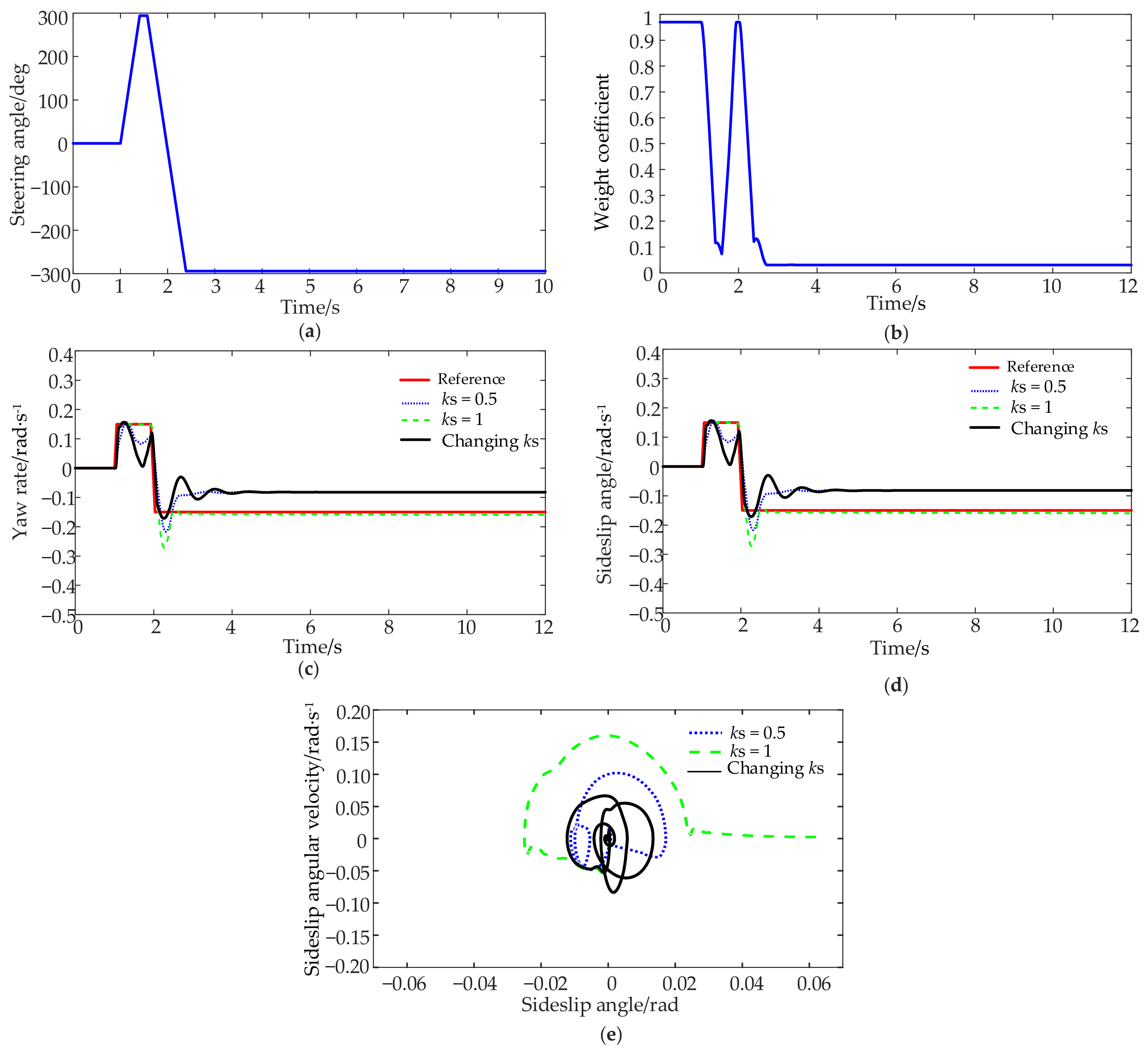
Figure 6a shows the input of steering angle in the fishhook condition. The steering wheel makes an emergency steering maneuver to the left through 294° at 1 s. After 0.2 s, the steering wheel makes emergency steering maneuver to the left through 584° and then remains in a state of steering to the right through 294°. Figure 6b shows the change in the weight coefficient of the sliding mode surface in this condition. The initial weight coefficient is 1. During the emergency steering process, the weight coefficient also changes between 0 and 1, and then maintains a low value. Figure 6c,d shows the yaw rate and sideslip angle under three direct yaw moment controllers with different weight coefficients. The extreme values of yaw rate are −0.2170 rad/s, −0.2712 rad/s and −0.1714 rad/s, respectively, and the extreme values of sideslip angle are 0.0172 rad, 0.643 rad and 0.0134 rad, respectively. Direct yaw moment controllers with different weight coefficients achieve different control effects. When the weight coefficient is 1, the yaw rate can track the expected value effectively, but the sideslip increases. According to the phase plane, the phase plane of the sideslip angle is not a closed curve, indicating that the vehicle stability is poor. When the weight coefficient is 0.5 and the weight coefficient changes, the extreme value of the yaw rate and sideslip angle is smaller than that with the weight coefficient 1. The controller response is fast, and the phase plane of the sideslip angle is small. That is, the change in the sideslip angle is more convergent, and the effect of inhibiting the sideslip angle is better.
From the simulation results of the double-lane-change and fishhook conditions, it can be seen that the direct yaw moment controller with different weight coefficients under different working conditions has achieved different controls for the complex driving conditions. The direct yaw moment controller with a variable weight coefficient designed in this paper has a better control effect on vehicle stability under various working conditions, which can improve the stability and adaptability of the vehicle.

4.2. Verification of Torque Distribution Controller

To verify the stability and self-adjusting ability of the torque distributor, the performance of the average distribution, load distribution, optimal torque distribution method and the proposed torque distribution method with road recognition under the double-lane-changing condition are tested and compared. The road adhesion is 0.2 and the vehicle speed is set to 80 km/h. The simulation results are shown in Figure 7.
It can be seen from Figure 7a,b that the stability controller based on average distribution, load distribution and optimal distribution can track the expected reference value well and improve the stability of the vehicle. Compared with average distribution and load distribution, the optimal distribution based on road coefficient recognition has a better control effect on the yaw rate and sideslip angle, and the static error of the yaw rate is smaller, so that the vehicle can be driven in accordance with the driver’s will and track the desired path better. Figure 7c shows the phase plane of the sideslip angle and the area enclosed by the phase plane is relatively smaller than that of the average or load distribution. That is, the vehicle stability margin is greater. The area of the phase plane enclosed by the optimal distribution without road adhesion coefficient recognition and the proposed torque distribution method with road adhesion coefficient recognition is close, demonstrating that the vehicle stability control effect is close. Figure 7d shows the estimated peak road adhesion coefficient. Compared with the real road adhesion 0.2, the error is within 10%. The estimated results can be applied to the optimal torque distribution method to improve the adaptability of vehicle stability control in complex driving conditions.
Figure 7e–h shows the torque distribution results under average distribution, load distribution, optimal distribution without road adhesion coefficient recognition and the proposed torque distribution with road adhesion coefficient recognition. Under average distribution, the torque of each wheel on the same side is the same, and the torque of the front and rear axles is symmetrical. Under load distribution, the torque of each wheel on both sides is symmetrical, while the torque of the front wheel is greater than that of the rear wheel. Compared with the average distribution and load distribution methods, the torque of a single tire is slightly larger in the optimal distribution method with and without the road adhesion coefficient. The yaw moment generated by the front axle torque is larger than that generated by the rear axle torque. The torque fluctuation range of each wheel is relatively gentle.

5. Discussion and Conclusions

This paper presents a hierarchical stability controller for electric vehicles with in-wheel motors. The upper direct yaw moment control layer adopts the adaptive sliding mode algorithm, whose coefficient of the variable sliding mode surface is selected by using a fuzzy algorithm. The lower torque distribution control layer is designed in combination with road adhesion coefficient recognition and restrictions of actuators. The direct yaw torque controller based on adaptive sliding mode is simulated and verified under double-lane-changing and fishhook conditions. The results show that the sliding mode variable structure algorithm and the changing weight coefficient of the combined control of the yaw rate and sideslip angle can effectively improve the stability and adaptability of the vehicle under extreme conditions. When different degrees of instability occur, the weight coefficient of the sliding surface cannot be fixed, and its value should be changed in real time according to different working conditions.
Simulation and verification are carried out on the proposed torque distribution based on road adhesion coefficient recognition under the double-lane-changing condition. The results show that the error between the road adhesion coefficient estimated by the designed recognition estimator and the actual road adhesion coefficient is within 10%. The proposed optimal torque distributor based on road adhesion coefficient recognition has a better control effect on the yaw rate and sideslip angle. The required yaw torque and the tire longitudinal force utilization rate are small, indicating a significant margin to deal with vehicle instability, which can improve the adaptability of vehicle under uncertain conditions.
The current work is still in the simulation verification stage, which is not perfect. In the future, energy saving optimization and braking energy recovery should be taken into consideration for torque distribution [34]. When improving vehicle handling stability, it should also enhance vehicle economy by improving energy consumption efficiency, and conducting hardware-in-the-loop or real vehicle verification.

Author Contributions

Conceptualization, P.G. and L.G.; methodology, J.F.; software, J.F. and X.Z.; validation, P.G. and L.G.; resources, L.G.; writing—original draft preparation, J.F. and X.Z.; writing—review and editing, P.G.; funding acquisition, P.G. and L.G. All authors have read and agreed to the published version of the manuscript.

Funding

This research was funded by the National Science Foundation of China, grant number 51975089 and 52175078, National Key Research and Development Program of China, grant number 2022YFB2602305, Ningbo Science and Technology Innovation 2025 Key Project, grant number 2022Z017, and Fundamental Research Funds for the Central Universities, grant number DUT22QN248.

Institutional Review Board Statement

Not applicable.

Informed Consent Statement

Not applicable.

Data Availability Statement

Not applicable.

Conflicts of Interest

The authors declare no conflict of interest.

Abbreviations

List of abbreviations used in the article (in alphabetical order).
EVBattery Electric Vehicle
DYCDirect Yaw Moment Control
GNLGeneral Nonlinear Model
MPCModel Predictive Control
PIDProportional Integral Differential
PNGVPartnership for a New Generation of Vehicle Battery Model
SMCSliding Mode Control

References

  1. He, S.W.; Fan, X.B.; Wang, Q.W.; Chen, X.B.; Zhu, S.W. Review on torque distribution scheme of four-wheel in-wheel motor electric vehicle. Machines 2022, 10, 619. [Google Scholar] [CrossRef]
  2. Joa, E.; Yi, K.; Hyun, Y. Estimation of the tire slip angle under various road conditions without tire-road information for vehicle stability control. Control Eng. Pract. 2019, 86, 129–143. [Google Scholar] [CrossRef]
  3. Liu, W.; Quijano, K.; Crawford, M.M. YOLOv5-tassel: Detecting tassels in RGB UAV imagery with improved YOLOv5 based on transfer learning. IEEE J. Sel. Top. Appl. Earth Obs. Remote Sens. 2022, 15, 8085–8094. [Google Scholar] [CrossRef]
  4. Zhai, L.; Wang, C.P.; Zhang, X.Y.; Hou, R.F.; Mok, Y.M.; Hou, Y.H. Handling stability control strategy for four-wheel hub motor-driven vehicle based on adaptive control for road adhesion. IET Intell. Transp. Syst. 2022, 16, 586–601. [Google Scholar] [CrossRef]
  5. Zhou, C.; Liu, X.H.; Xu, F.X. Intervention criterion and control strategy of active front steering system for emergency rescue vehicle. Mech. Syst. Signal Process. 2021, 148, 107160. [Google Scholar] [CrossRef]
  6. Zhang, H.; Wang, J.M. Vehicle lateral dynamics control through AFS/DYC and robust gain-scheduling approach. IEEE Trans. Veh. Technol. 2016, 65, 489–494. [Google Scholar] [CrossRef]
  7. Wang, H.B.; Zhou, J.T.; Hu, C.L.; Chen, W.W. Vehicle lateral stability control based on stability category recognition with improved brain emotional learning network. IEEE Trans. Veh. Technol. 2022, 71, 5930–5943. [Google Scholar] [CrossRef]
  8. Wu, W.; Lu, S.; Li, C. Adaptive coordinated stability control of vehicle considering stability margin. In Proceedings of the 2021 33rd Chinese Control and Decision Conference, Kunming, China, 22–24 May 2021; pp. 5191–5196. [Google Scholar]
  9. Hu, C.; Wang, Z.; Taghavifar, H.; Na, J.; Qin, Y.; Guo, J.; Wei, C. MME-EKF-based path-tracking control of autonomous vehicles considering input saturation. IEEE Trans. Veh. Technol. 2019, 68, 5246–5259. [Google Scholar] [CrossRef]
  10. Dong, J.; Li, J.; Gao, Q.; Hu, J.; Liu, Z. Optimal coordinated control of active steering and direct yaw moment for distributed-driven electric vehicles. Control Eng. Pract. 2023, 134, 105486. [Google Scholar] [CrossRef]
  11. Ahmed, A.A.; Ahmed, A.A.; Alarga, A.S.D.; Alsharif, A. Simulation research on vehicle handling and stability enhancement based on PID control technology. In Proceedings of the IEEE International Conference on Power, Electrical, Electronic and Industrial Applications, Dhaka, Bangladesh, 3–4 December 2021; pp. 10–15. [Google Scholar]
  12. Jung, H.; Jung, D.; Choi, S.B. LQR control of an all-wheel drive vehicle considering variable input constraint. IEEE Trans. Control Syst. Technol. 2022, 30, 85–96. [Google Scholar] [CrossRef]
  13. Majidi, M.; Asiabar, A.N. Stability enhancement of in-wheel motor drive electric vehicle using adaptive sliding mode control. Int. J. Adv. Manuf. Technol. 2022, 15, 23–33. [Google Scholar]
  14. Liu, C.; Liu, H.; Han, L.; Wang, W.; Guo, C. Multi-level coordinated yaw stability control based on sliding mode predictive control for distributed drive electric vehicles under extreme conditions. IEEE Trans. Veh. Technol. 2022, 72, 280–296. [Google Scholar] [CrossRef]
  15. Li, P.; Li, P.; Zhang, B.; Zhao, J.; Du, B. Velocity-based lateral stability control for four-wheel independently actuated electric vehicles with homogeneous polynomial approach. Int. J. Control Autom. Syst. 2021, 19, 255–266. [Google Scholar] [CrossRef]
  16. Liu, Z.; Qiao, Y.; Chen, X. A novel control strategy of straight-line driving stability for 4WID electric vehicles based on sliding mode control. In Proceedings of the 2021 5th CAA International Conference on Vehicular Control and Intelligence, Tianjin, China, 29–31 October 2021. [Google Scholar]
  17. Qin, Y.; Li, C.; Jing, H.; Cui, R.; Lei, Y. Lateral stability control of four-wheel-drive vehicle based on coordinated control of torque distribution and vehicle dynamics. In Proceedings of the 2022 Global Conference on Robotics, Artificial Intelligence and Information Technology, Chicago, IL, USA, 30–31 July 2022. [Google Scholar]
  18. Asiabar, A.N.; Kazemi, R. A direct yaw moment controller for a four in-wheel motor drive electric vehicle using adaptive sliding mode control. Proc. Inst. Mech. Eng. Part K-J. Multi-Body Dyn. 2019, 233, 549–567. [Google Scholar] [CrossRef]
  19. Yang, K.; Dong, D.X.; Ma, C.; Tian, Z.X.; Chang, Y.L.; Wang, G. Stability control for electric vehicles with four in-wheel-motors based on sideslip angle. World Electr. Veh. J. 2021, 12, 42. [Google Scholar] [CrossRef]
  20. Liu, W.; Xiong, L.; Xia, X.; Lu, Y.; Gao, L.; Song, S. Vision-aided intelligent vehicle sideslip angle estimation based on a dynamic model. IET Intell. Transp. Syst. 2020, 14, 1183–1189. [Google Scholar] [CrossRef]
  21. Ma, Y.; Chen, J.; Zhu, X.; Xu, Y. Lateral stability integrated with energy efficiency control for electric vehicles. Mech. Syst. Signal Process. 2019, 127, 1–15. [Google Scholar] [CrossRef]
  22. Wang, Y.; Zhao, Y.; Zhou, S.; Yan, Q.; Zhan, H.; Cheng, Y.; Yin, W. Impact of individual cell parameter difference on the performance of series–parallel battery packs. ACS Omega 2023, 8, 10512–10524. [Google Scholar] [CrossRef]
  23. Fukada, Y. Slip-angle estimation for vehicle stability control. Veh. Syst. Dyn. 1999, 32, 375–388. [Google Scholar] [CrossRef]
  24. Boada, B.L.; Boada, M.J.L.; Diaz, V. Vehicle sideslip angle measurement based on sensor data fusion using an integrated ANFIS and an Unscented Kalman Filter algorithm. Mech. Syst. Signal Process. 2016, 72–73, 832–845. [Google Scholar] [CrossRef]
  25. Mirzaeinejad, H.; Mirzaei, M.; Rafatnia, S. A novel technique for optimal integration of active steering and differential braking with estimation to improve vehicle directional stability. ISA Trans. 2018, 80, 513–527. [Google Scholar] [CrossRef] [PubMed]
  26. Najjari, B.; Mirzaei, M.; Tahouni, A. Decentralized integration of constrained active steering and torque vectoring systems to energy-efficient stability control of electric vehicles. J. Frankl. Inst. 2022, 359, 8713–8741. [Google Scholar] [CrossRef]
  27. Xiang, C.L.; Peng, H.N.; Wang, W.D.; Li, L.; An, Q.; Cheng, S. Path tracking coordinated control strategy for autonomous four in-wheel-motor independent-drive vehicles with consideration of lateral stability. Proc. Inst. Mech. Eng. Part D-J. Automob. Eng. 2021, 235, 1023–1036. [Google Scholar] [CrossRef]
  28. Leng, B.; Jin, D.; Xiong, L.; Yang, X.; Yu, Z.P. Estimation of tire-road peak adhesion coefficient for intelligent electric vehicles based on camera and tire dynamics information fusion. Mech. Syst. Signal Process. 2021, 150, 107275. [Google Scholar] [CrossRef]
  29. Burckhardt, M. Fahrwerktechnik: Radschlupfregel Systeme; Vogel-Verlag: Wurzburg, Germany, 1993; pp. 62–70. [Google Scholar]
  30. Vieira, D.; Orjuela, R.; Spisser, M.; Basset, M. An adapted Burckhardt tire model for off-road vehicle applications. J. Terramech. 2022, 104, 15–24. [Google Scholar] [CrossRef]
  31. Crocetti, F.; Costante, G.; Fravolini, M.L.; Valigi, P. Tire-road friction estimation and uncertainty assessment to improve electric aircraft braking system. In Proceedings of the 29th Mediterranean Conference on Control and Automation, Puglia, Italy, 22–25 June 2021; pp. 330–335. [Google Scholar] [CrossRef]
  32. Guo, L.; Ge, P.S.; Sun, D.C. Torque distribution algorithm for stability control of electric vehicle driven by four in-wheel motors under emergency conditions. IEEE Access 2019, 7, 104737–104748. [Google Scholar] [CrossRef]
  33. Kamidi, V.R.; Kim, J.; Fawcett, R.T.; Ames, A.D.; Hamed, K.A. Distributed quadratic programming-based nonlinear controllers for periodic gaits on legged robots. IEEE Control Syst. Lett. 2022, 6, 2509–2514. [Google Scholar] [CrossRef]
  34. Hu, L.; Tian, Q.; Zou, C.; Huang, J.; Ye, Y.; Wu, X. A study on energy distribution strategy of electric vehicle hybrid energy storage system considering driving style based on real urban driving data. Renew. Sustain. Energy Rev. 2022, 162, 112416. [Google Scholar] [CrossRef]
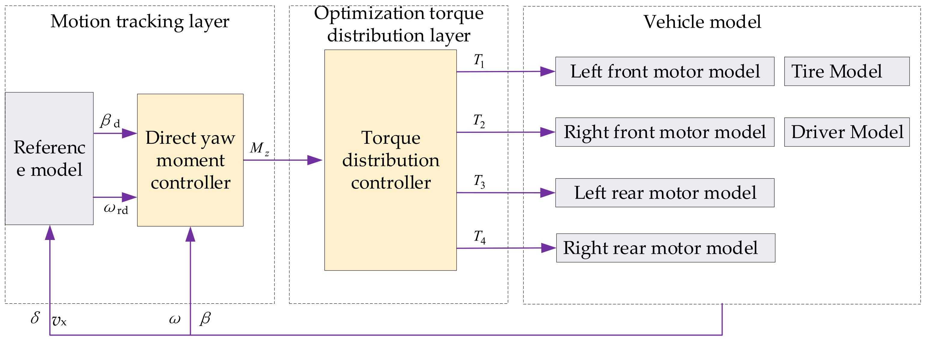
Figure 1. Framework of the adaptive stability hierarchical control system.
Sustainability 15 08660 g001
Figure 2. Membership function for (a) input variable and (b) output variable and (c) relationship of the input and output variable.
Sustainability 15 08660 g002
Figure 3. Flowchart of torque distribution controller.
Sustainability 15 08660 g003
Figure 4. Membership function for (a) Slip rate; (b) Adhesion utilization coefficient when slip rate is S; (c) Adhesion utilization coefficient when slip rate is B; (d) Road weight coefficient.
Sustainability 15 08660 g004
Figure 5. Direct yaw moment control results in double-lane-changing condition. (a) Trajectory of double lane changing; (b) Curve of weight coefficient; (c) Curve of yaw rate; (d) Curve of sideslip angle; (e) Phase plane of sideslip angle.
Sustainability 15 08660 g005
Figure 6. Direct yaw moment control results in fishhook condition. (a) Input of steering angle; (b) Curve of weight coefficient; (c) Curve of yaw rate; (d) Curve of sideslip angle; (e) Phase plane of sideslip angle.
Sustainability 15 08660 g006
Figure 7. Torque distribution control results in double-lane-changing condition. (a) Curve of yaw rate; (b) Curve of sideslip angle; (c) Phase plane of sideslip angle; (d) Curve of peak road adhesion coefficient; (e) Torque distribution results of average distribution; (f) Torque distribution results of load distribution; (g) Torque distribution results of optimal distribution; (h) Torque distribution results of the proposed controller.
Sustainability 15 08660 g007
Table 1. Power battery cell parameters.
ParameterValue
Capacity5.00 Ah
Rated working voltage3.60 V
Maximum voltage limit3.65 V
Minimum voltage limit2.50 V
Table 2. Vehicle parameters.
ParameterSymbolValue
Massm1416 kg
Moment of inertia about Z axisIZ1523 kg·m2
Distance from front axis to the center of gravitya1.016 m
Distance from rear axis to the center of gravityb1.562 m
WheelbaseL2.578 m
Tire radiusR0.357 m
Front tire cornering stiffnesskf−65,520 N/rad
Rear tire cornering stiffnesskr−57,200 N/rad
Table 3. Peak adhesion coefficients for each reference road.
TypePeak Adhesion Coefficient
Ice0.05
Snow0.19
Wet pebble0.34
Road 10.50
Road 20.65
Wet asphalt0.80
Dry cement1.09
Road 31.25
Table 4. Road coefficient recognition rules.
Slip RateAdhesion CoefficientRS1RS2RS3RS4RS5RS6RS7RS8
SRS1SVSGSDSDSDSDSDSD
RS2SMSVSDSDSDSDSDSD
RS3SGSSSVSMSGSDSDSD
RS4SDSDSMSVSMSGSDSD
RS5SDSDSDSMSVSSSDSD
RS6SDSDSGSMSSSVSSSM
RS7SDSDSDSDSDSSSVSM
RS8SDSDSDSDSDSMSSSV
BRS1SVSGSDSDSDSDSDSD
RS2SMSVSGSDSDSDSDSD
RS3SGSSSVSSSGSDSDSD
RS4SDSDSMSVSSSDSDSD
RS5SDSDSDSMSVSSSMSS
RS6SDSDSGSMSSSVSSSM
RS7SDSDSDSDSDSSSVSM
RS8SDSDSDSDSDSMSMSV
Disclaimer/Publisher’s Note: The statements, opinions and data contained in all publications are solely those of the individual author(s) and contributor(s) and not of MDPI and/or the editor(s). MDPI and/or the editor(s) disclaim responsibility for any injury to people or property resulting from any ideas, methods, instructions or products referred to in the content.