Article

Driveline Oscillation Damping for Hybrid Electric Vehicles Using Extended-State-Observer-Based Compensator

1
School of Automotive Studies, Tongji University, Shanghai 200092, China
2
School of Customs and Public Administration, Shanghai Customs College, Shanghai 201315, China
*
Author to whom correspondence should be addressed.
Sustainability 2023, 15(10), 8143; https://doi.org/10.3390/su15108143
Submission received: 4 April 2023 / Revised: 11 May 2023 / Accepted: 15 May 2023 / Published: 17 May 2023

Abstract

:
Driveline oscillation is a significant concern in the context of hybrid electric vehicles (HEVs), because it can adversely affect the vehicles’ sustainability. The reason for this is that the oscillation not only diminishes the longevity of components due to high mechanical contact stress but also results in poor driving comfort, which in turn reduces customer satisfaction. To address the issue of driveline oscillation effectively, two critical challenges, namely the time-varying torque load and driveline backlash, need to be tackled. To this end, this study constructs a control-oriented model of a second-order system plus a dead zone for the driveline backlash. An extended state observer is designed in order to estimate the unmeasurable load torque. As such, an extended-state-observer-based compensator is proposed to suppress driveline oscillations for HEVs. To evaluate the control and observation performance of the proposed extended-state-observer-based compensator, simulation and engine-in-loop experiments are conducted. Results obtained in the time and frequency domains reveal that the proposed control scheme substantially reduces driveline oscillation.

1. Introduction

Hybrid electric vehicles (HEVs), as a sustainable transportation option [1,2], offer improved fuel economy and reduced emissions compared to traditional internal combustion engine (ICE) vehicles [3]. However, tip-in or back-out maneuvers of HEV drivelines can result in a prevalent and troublesome oscillation problem, especially in vehicles with long drive shafts [4,5]. This driveline oscillation reduces the sustainability of HEVs because it not only shortens component life due to the high mechanical contact stress, but also reduces customer acceptance due to poor driving comfort [6]. Therefore, driveline oscillation damping has garnered considerable attention from researchers as a means to improve the sustainability of HEVs [7,8,9].
Driveline oscillation damping methods can be broadly divided into two categories [10]: passive devices, such as torsional vibration dampers, which reduce the transmission of vibrations from the driveline to the vehicle body [11]; and advanced active damping techniques, which suppress the vibrations generated by the driveline. Although passive devices are effective, they introduce additional hardware that increases the overall cost of the driveline system [12]. Furthermore, active damping techniques are more desirable because they act as software control systems and do not require additional hardware costs [13]. HEVs enable the active torque control of the traction motor to facilitate the implementation of the active damping technique.
Active damping techniques have mainly been focused on designing algorithms for the control system. Some controllers have been designed to alleviate torsional vibration by generating compensation torque based on the linear dynamic model of the driveline [14,15]. Linear matrix inequalities have been used to design a linear parameter-varying dynamic-output feedback controller that compensates for the torque ripples in HEVs [16]. A linear-quadratic-Gaussian controller was designed to actively dampen the oscillations of heavy-duty trucks in Reference [17]. However, the linear dynamic model is insufficient to represent the nonlinear behavior of backlash, resulting in inconsistencies between the real system and the model. Other controllers have been designed using the nonlinear dynamic model. For example, Yonezawa et al. presented a fuzzy-reasoning-based compensation algorithm in Reference [18] in order to enhance the robustness of the oscillation damping controller. Chen et al. proposed a pulse cancellation algorithm for by dual-mode hybrid vehicles to suppress torque fluctuation [19]. These methods require a high-fidelity model of the driveline in order to achieve effective control. However, the high-fidelity model of the driveline system is supported by the high-order nonlinear model, which is too complicated for the design of the controller and observer. In addition, the torque load of the driveline cannot be measured, making it extremely challenging to build a high-fidelity model.
In order to suppress driveline oscillation in HEVs effectively, two critical issues, namely time-varying torque load and nonlinear driveline backlash, must be addressed. While addressing these issues, the introduction of high-order models must be avoided. To achieve this objective, this study proposes an extended-state-observer-based compensator to actively suppress the driveline oscillation of HEVs. The procedure for damping driveline oscillation can be summarized as follows. First, a control-oriented model, which which is comprised of a second-order system with a dead zone to facilitate the control algorithm design, is selected. Second, a torque feedback compensator is designed using the pole placement method. This method is simple yet effective. Third, an extended state observer is designed to estimate system states and the unmeasurable load torque. The observer’s stability is guaranteed by using a Lyapunov function. By implementing these steps, the driveline oscillation can be significantly dampened.
The remainder of this paper is organized as follows. In the Modeling section, we establish a model for the gearbox with backlash; the dynamic model for the drive shaft, tire, and vehicle; and a control-oriented model. The Controller Design section outlines the design of the torque compensator and an extended state observer. In the Results section, we verify the effectiveness of the control strategy through simulations and experiments. Finally, the Conclusion section provides a summary of the study’s findings.

2. Modeling

This section outlines the modeling of the entire driveline of the investigated HEV, as depicted in Figure 1. The physical structure of the driveline is considered, and each component is modeled separately. Due to the complexity of the established driveline model for designing the system controller, a simplified model is subsequently developed to represent the primary dynamic characteristics of the driveline.

2.1. System Model

2.1.1. Gearbox with Backlash

The gear box is modeled as an inertia mass, and the rotational speed is determined by the gear ratio. Newton’s second law of rotational motion governs the transmitted rotational speed, given by
I op ω ˙ op = T op D op ω op T g - in ,
where T op is the torque of the clutch output shaft, T g - in is the input torque of the gearbox input shaft, D op is the viscous friction coefficient of the gearbox, I op is the equivalent moment of inertia of the gearbox, and ω op is the rotation speed of the gearbox input shaft. The input torque of the gearbox input shaft T op is determined by the engine torque T e and the motor torque T m :
T op = T m + T e .
As shown in Figure 1, the contact between the gear teeth is modeled as a spring and damper system [20] governed by
F contact = K con q relative + C con q ˙ relative ,
where K con is the equivalent stiffness coefficient, C con is the equivalent damping coefficient, q relative is the relative displacement of the contact point, and q ˙ relative is the relative speed of the contact point. The relative speed between the gear teeth is given by
q ˙ relative = R g - in ω op + R g - out ω ds ,
where R g - in is the radius of the gearbox input gear, R g - out is the radius of the gearbox output gear, and ω ds is the rotational speed of the drive shaft. The backlash of the whole driveline is lumped together as the gear backlash, and the following model is used to describe it:
F transfer = F contact q relative d backlash 2 0 q relative < d backlash 2
where F transfer is the transfer force of gears, and d backlash is the backlash gap. The torques transmitted by gears can be expressed in following form,
T g - in = F transfer R g - in T ds = F transfer R g - out ,
where T ds is the input torque of the drive shaft.

2.1.2. Drive Shaft and Tire

According to Newton’s second law, the equations of motion for the drive shaft and tire are given by
I ds ω ˙ ds = T ds T tire I tire ω ˙ tire = T tire T body ,
where I ds and I tire are the equivalent moments of inertia of the drive shaft and tire, and ω tire is the tire’s rotational speed. The drive shaft and tire can be modeled as damped torsional flexibilities, and the torques T tire and T body can be expressed as:
T tire = K ds θ ds θ tire + C ds ω ds ω tire T body = K tire θ tire θ body + C tire ω tire ω body ,
where K ds and K tire are the equivalent stiffness coefficients of the drive shaft and tire, respectively; C ds and C tire are the equivalent damping coefficient of the drive shaft and tire, respectively; θ ds , θ tire , and θ body are the rotation angles of the drive shaft, tire, and vehicle body, respectively; and ω tire and ω body are the rotational speeds of the tire and vehicle body, respectively.

2.1.3. Vehicle Body

The dynamics of the vehicle can be described as follows:
I body ω ˙ body = T body T load ,
where I body is the equivalent inertia of the vehicle body, and T load is the load torque of the vehicle. The load torque, which is contributed by the road and the air, can be modeled as
T load = M g ( f cos α + sin α ) r w + 1 2 C D A D ρ ω load r w 2 r w ,
where M is the vehicle mass, g is the gravity acceleration, f is the rolling resistance coefficient, α is the slope angle, r w is the radius of the tire, C D is the air resistance coefficient, A D is the reference area, and ρ is the mass density of the air.

2.2. Control-Oriented Model

The model established in Section 2.1 is complex for directly designing the control algorithm. Hence, a simplified model is used to represent the torque transfer relationship from the gearbox input shaft to the vehicle body (from T op to T body ), as depicted in Figure 2. The simplified model is a second-order system with a dead zone, wherein the friction of the whole driveline is modeled by the dead zone, whereas the second-order system presents the main dynamic characteristic. With the dead zone, the control input u can be expressed as follows:
u = T op c r T op c r 0 c l < T op < c r T op c l T op c l ,
where c r and c l are the bounds of the dead zone. The entire system becomes a third-order system, written in state–space form as:
x ˙ = A x + B u u + B d T load , y = C x ,
where x = T body T ˙ body ω body , A = 0 1 0 ω n 2 2 ξ ω n 0 1 I body 0 0 , B u = 0 ω n 2 0 , B d = 0 0 1 I body , C = 0 0 1 .

3. Controller Design

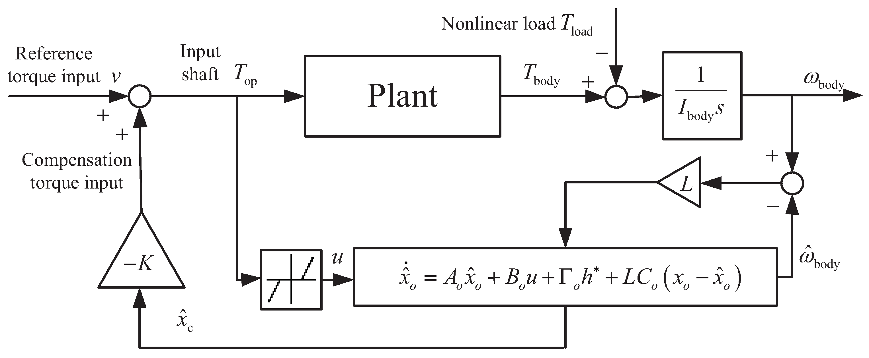
This section presents the design of a compensator for damping driveline oscillations. The control scheme of the proposed extended-state-observer-based compensator is depicted in Figure 3. The torque compensator is designed using pole placement. An extended state observer is used to estimate unmeasurable states and load torque.

3.1. Torque Compensator

Given that the oscillations in the driveline are caused by under-damping, the pole placement method [21] is used to place the closed-loop poles of the driveline at a predetermined location in the s-plane. By doing so, the under-damping of the driveline can be compensated for.
Based on the simplified model shown in Figure 2, the driveline dynamics can be described by the state–space equation:
x ˙ c = A c x c + B c u ,
where x c = T body T ˙ body , A c = 0 1 ω n 2 2 ξ ω n , and B c = 0 ω n 2 . The driveline dynamics (13) represent the reduced-order form of the system (12).
A control input proportional to the state vector is selected as
u = K x c + v ,
where v is the reference torque input provided by the driver and K x c is the compensation torque input provided by the compensator. Given that the state vector x c is unmeasurable, it is replaced by its estimated value x ^ c in practical applications. Substituting Equation (15) into system (13), the state–space equation becomes
x ˙ c = ( A c B c K ) x c + B c v .
The poles of the closed-loop feedback system are determined by the characteristic equation of the matrix A c B c K . A robust pole placement method proposed by Reference [22] is used to determine the feedback gain K in Equation (15) as part of the proposed state compensation strategy. The practical implementation of the robust pole placement method consists of three fundamental steps: Step A, Step X, and Step F. In Step A, the matrix B c is decomposed. In Step X, gradient iterative methods are used to select vectors that ensure the system is well conditioned. Step F involves solving linear equations to compute the feedback gain K. Steps A and F are consistent across all methods, whereas Step X is the critical step that employs an iterative process to minimize the measures of robustness.
Although the pole placement method itself is not new, the application of robust pole placement in the context of the proposed extended-state-observer-based compensator is innovative and unique. Specifically, the method was used to place the closed-loop poles of the system in a desired location, thereby ensuring good oscillation-damping performance. The proposed state compensation strategy differs from existing methods in the literature by incorporating an extended state observer to estimate the unmeasurable load torque and compensate for the nonlinear driveline backlash. This combination of state compensation and disturbance compensation is novel and has the potential to improve the control performance of HEVs.

3.2. Extended State Observer

The extended state observer is a tool used in control engineering for estimating the state variables of a system, especially when some of these variables cannot be directly measured or are affected by disturbances. The basic concept behind the extended state observer involves developing an additional dynamic system that models the uncertainties and disturbances that affect the main system and then utilizing this model to estimate the unknown variables. Specifically, the extended state observer includes a state observer for the main system and an extended state term for the disturbance. The load torque of a moving vehicle, which is influenced by the road slope and cannot be measured directly, can be regarded as a disturbance. Additionally, the system state vector x c is unmeasurable. Therefore, this study developed an extended state observer in order to estimate the load torque and system states.
Considering that no prior information is available regarding the derivative of the load torque, a bounded variable h ( t ) has been introduced to represent it as T ˙ load = h ( t ) . Assuming that the load torque remains constant or slowly varies during vehicle acceleration, the variable h ( t ) remains small. By treating the load torque T load as a system state, system (12) is extended as an augmented system:
x ˙ T ˙ load = A B d 0 0 x T load + B u 0 u + 0 1 h = A o x o + B o u + Γ o h y = C 0 x T load = C o x o .
First, we verify whether the augmented system is observable when the system output is the rotation speed of the vehicle wheel. The system is observable if the matrix C o C o A o C o A o 2 C o A o 3 T has a full rank. It is evident that the rank of the matrix C o C o A o C o A o 2 C o A o 3 T is four, indicating that the augmented system is indeed observable.
Next, the correction term for the extended state observer is selected as the difference between the rotation speed of the vehicle wheel ω body and its estimated value ω ^ body . Using this, the extended state observer is designed as follows:
x ^ ˙ o = A o x ^ o + B o u + Γ o h * + L ω body ω ^ body = A o x ^ o + B o u + Γ o h * + L C o x o x ^ o ,
where L = l 1 l 2 l 3 l 4 T is the observer gain and h * is the nominal value of the derivative of the load torque.
Let x ˜ o = x o x ^ o , then the error dynamics of the extended state observer are obtained by subtracting (17) from (16):
x ˜ ˙ o = x ˙ o x ^ ˙ o = ( A o L C o ) x ˜ + Γ o δ ,
where δ = h h * represents the model deviation of the derivative of the load torque. The extended state observer is asymptotically stable when the matrix A o L C o is Hurwitz and the derivative of the load torque h is known accurately, that is, δ = 0 .
However, if δ 0 due to inaccurate knowledge of h, then we define a Lyapunov function as V = x ˜ T P x ˜ , where P > 0 , and differentiate it along the error dynamics (18). We obtain
V ˙ = x ˜ ˙ o T P x ˜ o + x ˜ o T P x ˜ ˙ o = [ ( A o L C o ) x ˜ o + Γ o δ ] T P x ˜ o + x ˜ o T P [ ( A o L C o ) x ˜ o + Γ o δ ] = x ˜ o T [ ( A o L C o ) T P + P ( A o L C o ) ] x ˜ o + 2 δ Γ o T P x ˜ o .
The application of Young’s inequality to the last term of the aforementioned equality leads to
δ Γ o T P x ˜ o κ 1 x ˜ o T x ˜ o + δ 2 4 κ 1 Γ o T P P Γ o ,
with κ 1 > 0 . The derivative of the Lyapunov function V becomes
V ˙ x ˜ o T [ ( A o L C o ) T P + P ( A o L C o ) + 2 κ 1 I ] x ˜ o + δ 2 2 κ 1 Γ o T P P Γ o ,
where I is the unit matrix.
By selecting the observer gain L to satisfy the following equality:
( A o L C o ) T P + P ( A o L C o ) + 2 κ 1 I = Q
with Q > 0 , we arrive at the relationship
V ˙ x ˜ T Q x ˜ + δ 2 2 κ 1 Γ o T P P Γ o .
This relationship implies that the extended state observer is input-to-state stable in the presence of bounded model deviation δ [23]. Specifically, the derivative of the Lyapunov function V is bounded by a negative semi-definite matrix Q , multiplied by the squared norm of the error x ˜ , and a term proportional to the squared norm of the model deviation δ .

4. Simulation Results

Simulations were carried out in MATLAB/Simulink, in order to evaluate the effectiveness of the designed control algorithm, using the plant model of the HEV driveline and the proposed control scheme. This section presents the results of these simulations, which include an assessment of the performance of the designed controller and the extended state observer as well as an analysis of the observer results with different initial state values.
The proposed control scheme involves determining the observer and feedback gains. The observer gain is first adjusted based on the stability condition (23). The appropriate order of magnitude of the observer gain can be determined by observing the observation error. Subsequently, the gain is fine-tuned to ensure optimal performance. After the tuning process, the observer gain is set to L = [4,156,000, 2,508,900, 300, −963,400] T . The chosen damping value is set to eight times that of the original damper after evaluating the oscillation-damping effectiveness. The feedback gain of K = [ 0 , 0.00737 ] is attained by using the desired damping value and the robust pole placement approach.

4.1. Control Performance of the Designed Controller

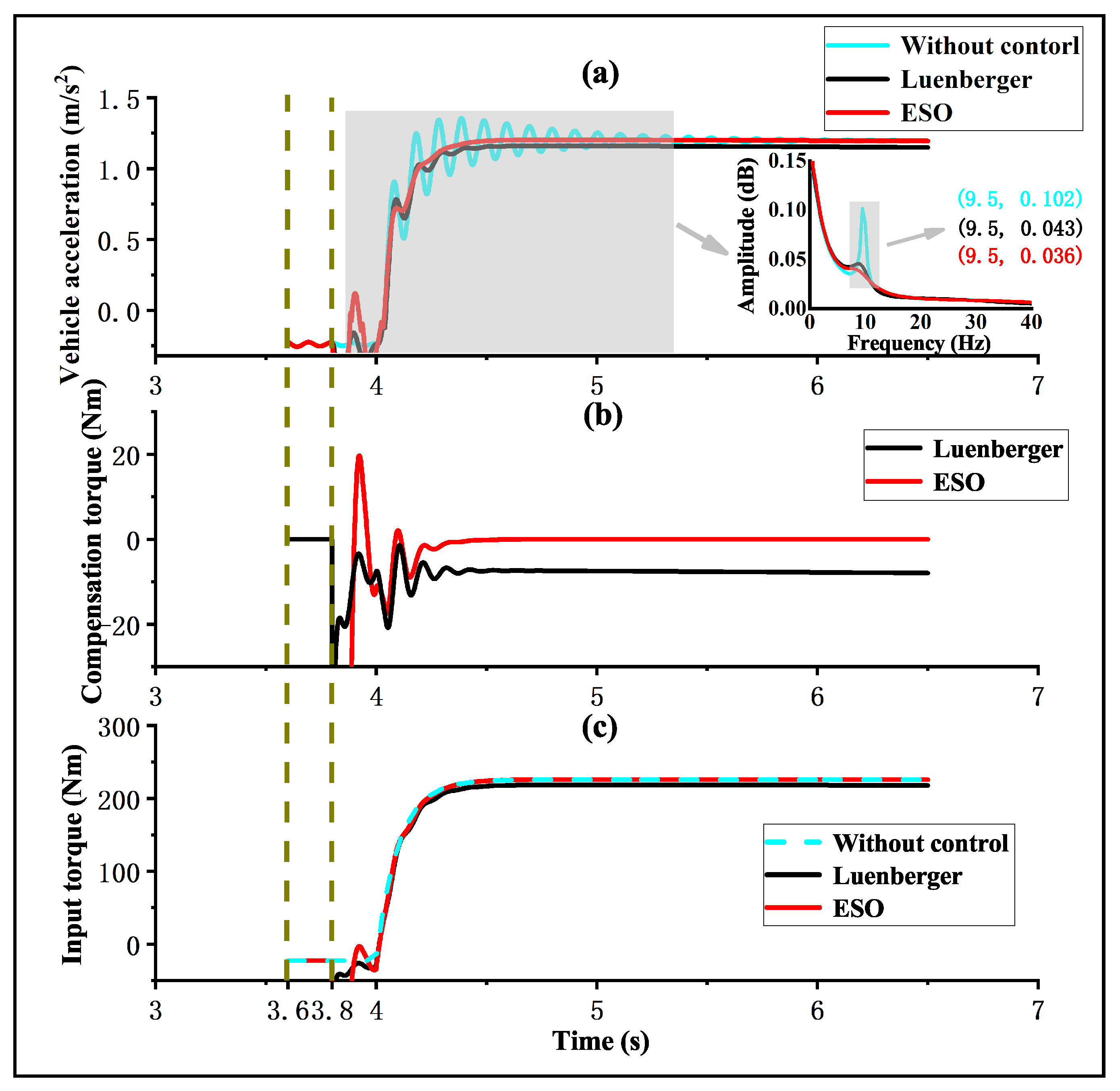
In the simulation, a tip-in operation is utilized as the driveline oscillation scenario. The control performance of the observer-based controller is illustrated for the test scenario in Figure 4. “Without control” refers to the case where no compensation torque is applied. The term “Luenberger” denotes the compensation torque obtained via state feedback, with the state observed using a Luenberger state observer. “ESO” refers to the compensation torque obtained by the state feedback process, where the state is observed using an extended state observer. The observer begins working at 3.6 s, and the observer-based compensator starts working at 3.8 s. As shown in Figure 4, at 4 s, the input torque sharply increases, resulting in rapid vehicle acceleration. When no controller is applied, this acceleration produces a significant chattering vibration. Compared with the non-observer-based controller, the controllers using the Luenberger state observer and extended state observer significantly reduce chattering during the acceleration process. Specifically, the extended-state-observer-based controller achieves better control performance that result in almost no chattering. The magnified graph in Figure 4a displays the amplitude spectrum of the corresponding vehicle acceleration, showing that the main frequency of the vehicle acceleration chattering is 9.5 Hz. The amplitudes generated by no control, Luenberger observer, and extended state observer at this frequency are 0.102, 0.043, and 0.036, respectively. The proposed extended-state-observer-based controller reduces chattering during acceleration from the perspective of the amplitude spectrum. Therefore, the proposed controller substantially dampens driveline oscillations.
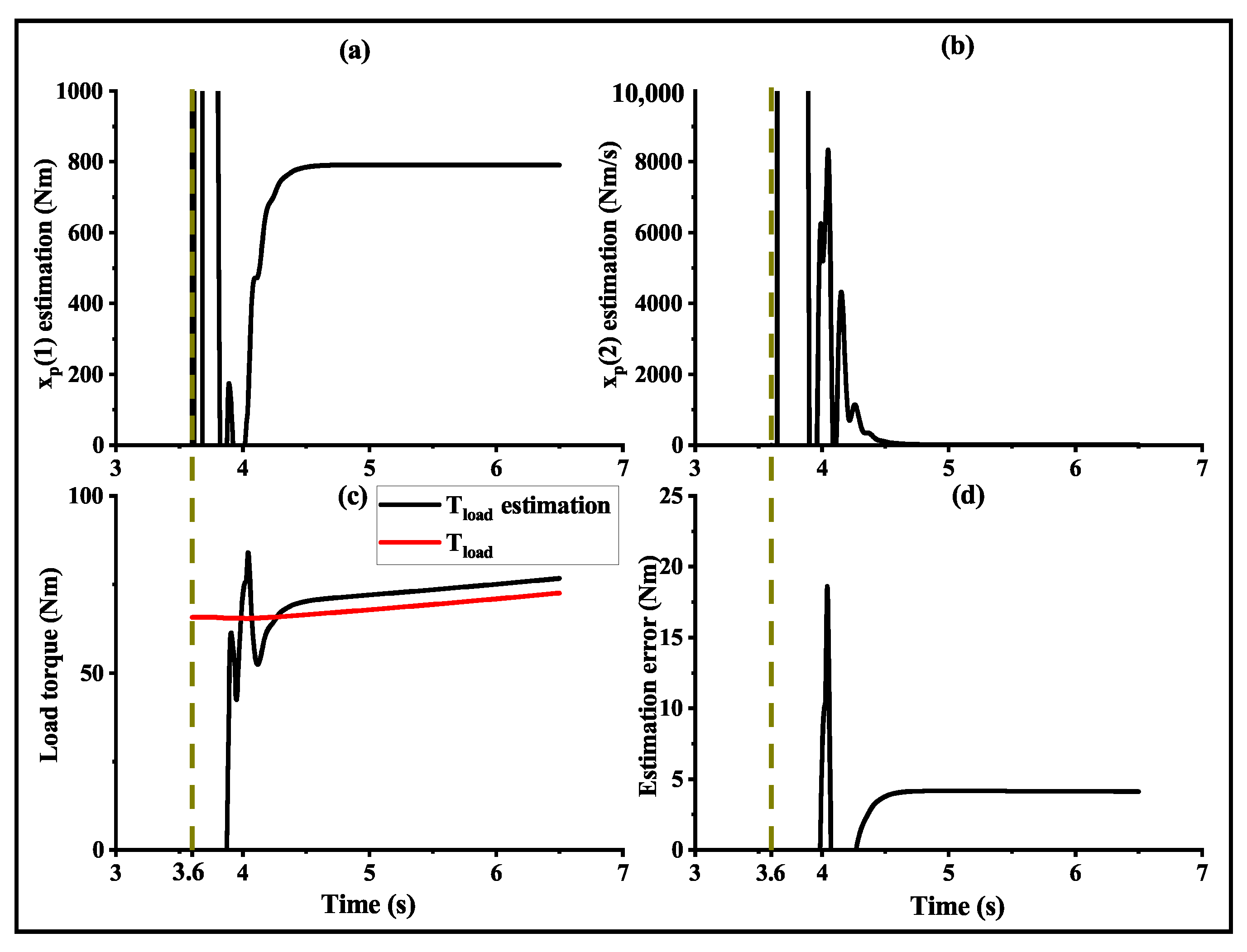
The performance of the extended state observer in the tip-in operation is illustrated in Figure 5. Additionally, the estimation error of the load torque is presented in order to evaluate the observer’s design. At approximately 3.6 s, the observer is activated, and at around 4 s, the observed values gradually converge. The results demonstrate that the estimated value from the observer is in good agreement with the actual value, with a steady-state error deviation of less than 5 Nm after convergence.
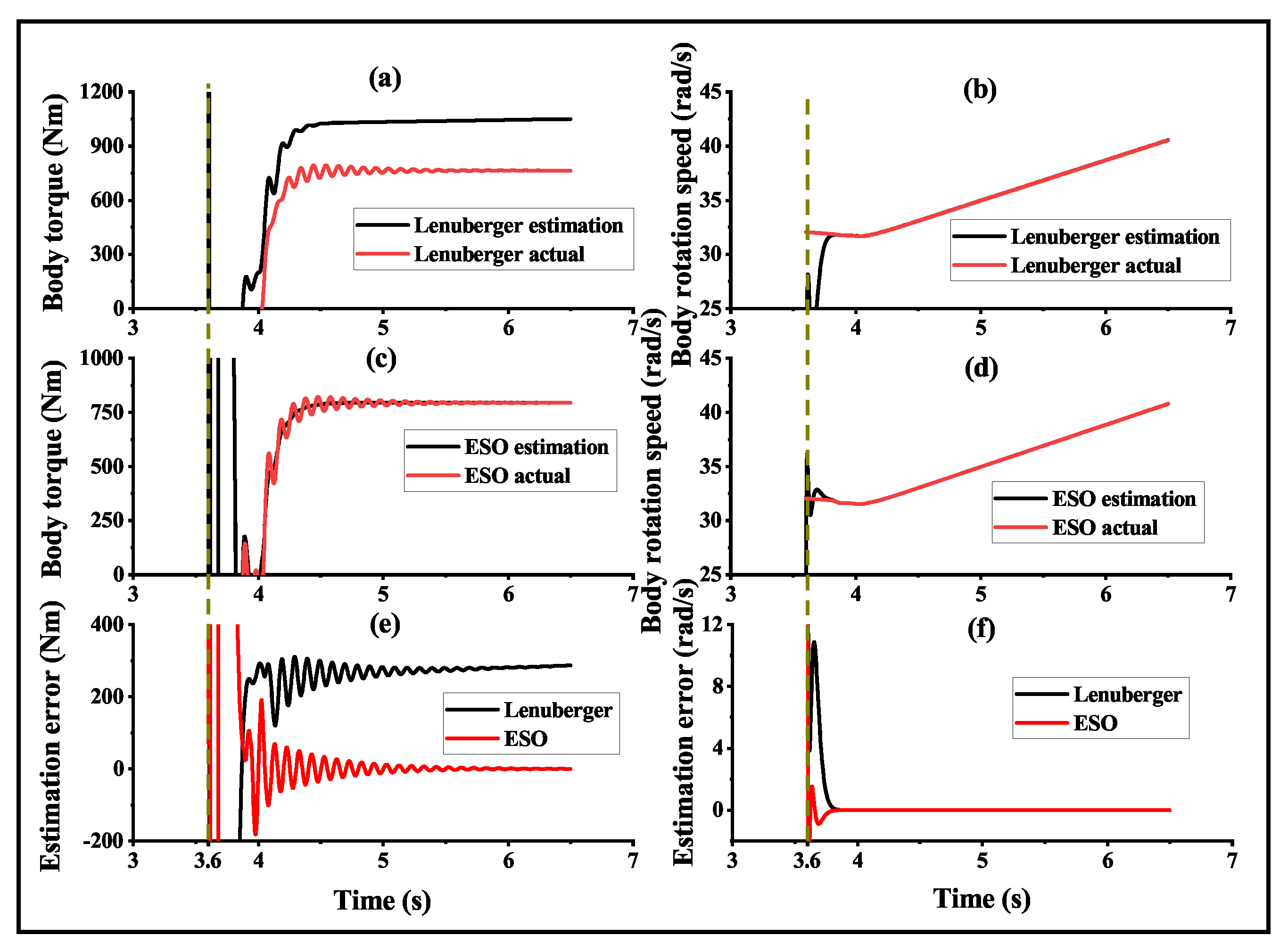
In order To highlight the advantages of the designed extended state observer, a comparison was made between the extended state observer and the Luenberger state observer, as shown in Figure 6. Figure 6a,b show the body torque and body rotation speed as estimated by the Luenberger state observer, whereas Figure 6c,d show the observation results for the extended state observer. Figure 6e,f depict the observation errors between the estimated values and the actual values for the two observers. From the estimation error of Figure 6, the extended state observer outperforms the Luenberger state observer in terms of estimation accuracy. Specifically, the extended state observer achieves near-zero error in its estimation of the body torque, whereas the Luenberger state observer’s error remains around 300 Nm. Similarly, the extended state observer’s estimation error for body rotation speed converges faster towards zero compared to the Luenberger state observer.

4.2. Observation Results for Different Initial State Values

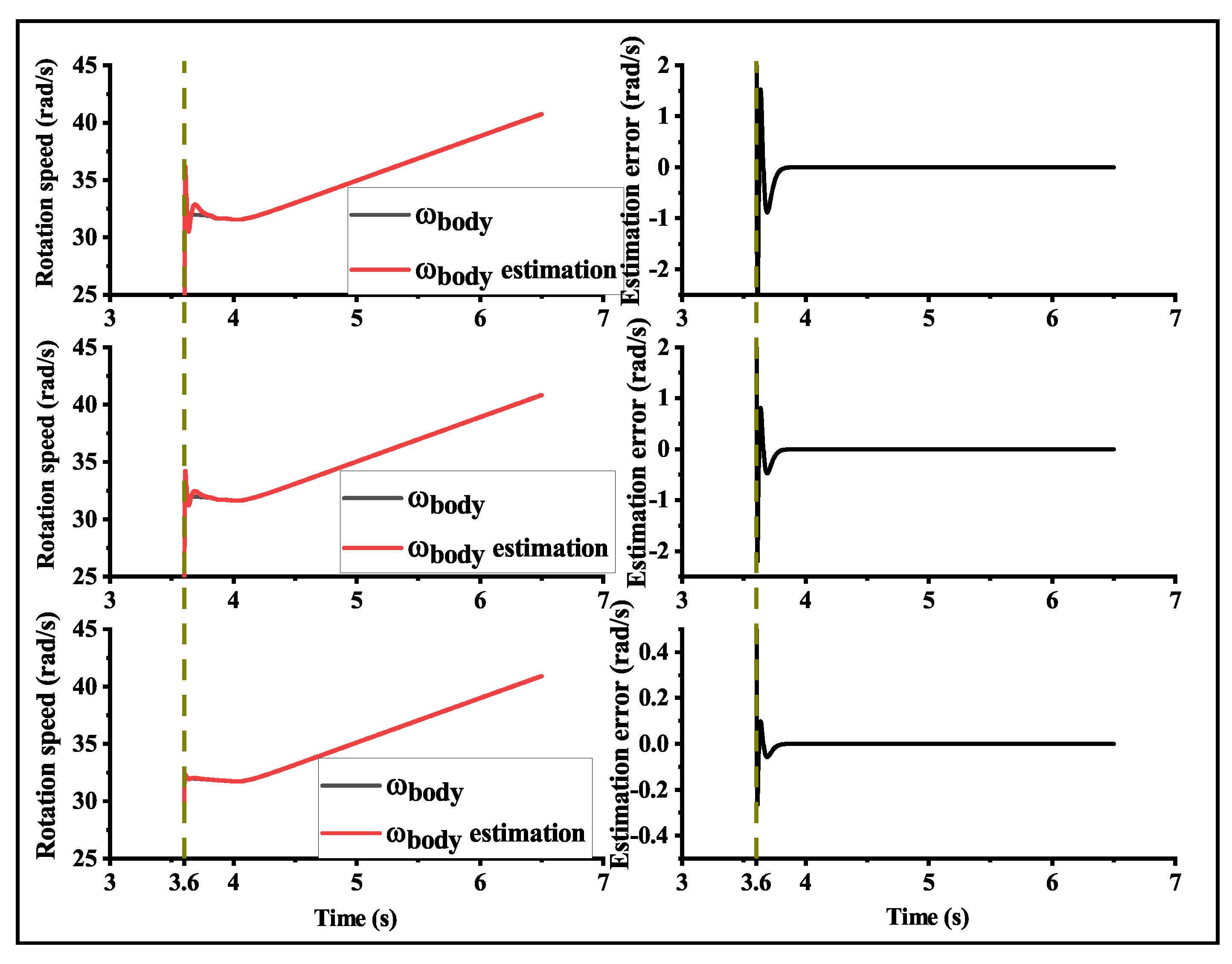
In order to investigate the impact of different initial values on the convergence of the observer, we tested the designed observer with various initial state values. As depicted in Figure 7, “ ω body ” is the actual value of the rotation speed of the vehicle body, “ ω body estimation” is the estimated value of the rotation speed of the vehicle body, we selected initial state values of [ 0 , 0 , 0 , 0 ] , [ 0 , 0 , 15 , 0 ] , and [ 0 , 0 , 30 , 0 ] from top to bottom. These values represent different rotational speeds of the vehicle body. As the initial value of the rotation speed of the vehicle body increases, the estimated results of the observer become increasingly closer to the true values, and for an initial value of 30, almost no estimation error was observed throughout the entire simulation process. However, regardless of the initial value, the estimation error of the observer can converge within 0.2 s after the controller is activated, indicating that different initial values do not have a significant impact on the observer’s estimation accuracy.

5. Experimental Results

Experiments were conducted to further evaluate the proposed control scheme using a test platform, as shown in Figure 8. During the experiments, a gasoline engine was utilized as the traction engine of the HEV, and the plant model and the proposed control scheme were constructed using MATLAB/Simulink. The engine test bench interacted with the plant simulation, making the test platform an engine-in-loop experimental platform. Further information about the engine test bench can be found in Reference [24]. The gasoline engine received the reference torque command, whereas the dynamometer simulated the external vehicle speed by providing a desired engine speed. The plant model received the signal of the real engine torque from the engine test bench and output the corresponding engine speed to the bench. The proposed observer-based controller implemented its algorithm by outputting the torque command, which was executed by the motor model as the compensated torque command.

5.1. Performance Evaluation for Two Types of Accelerations

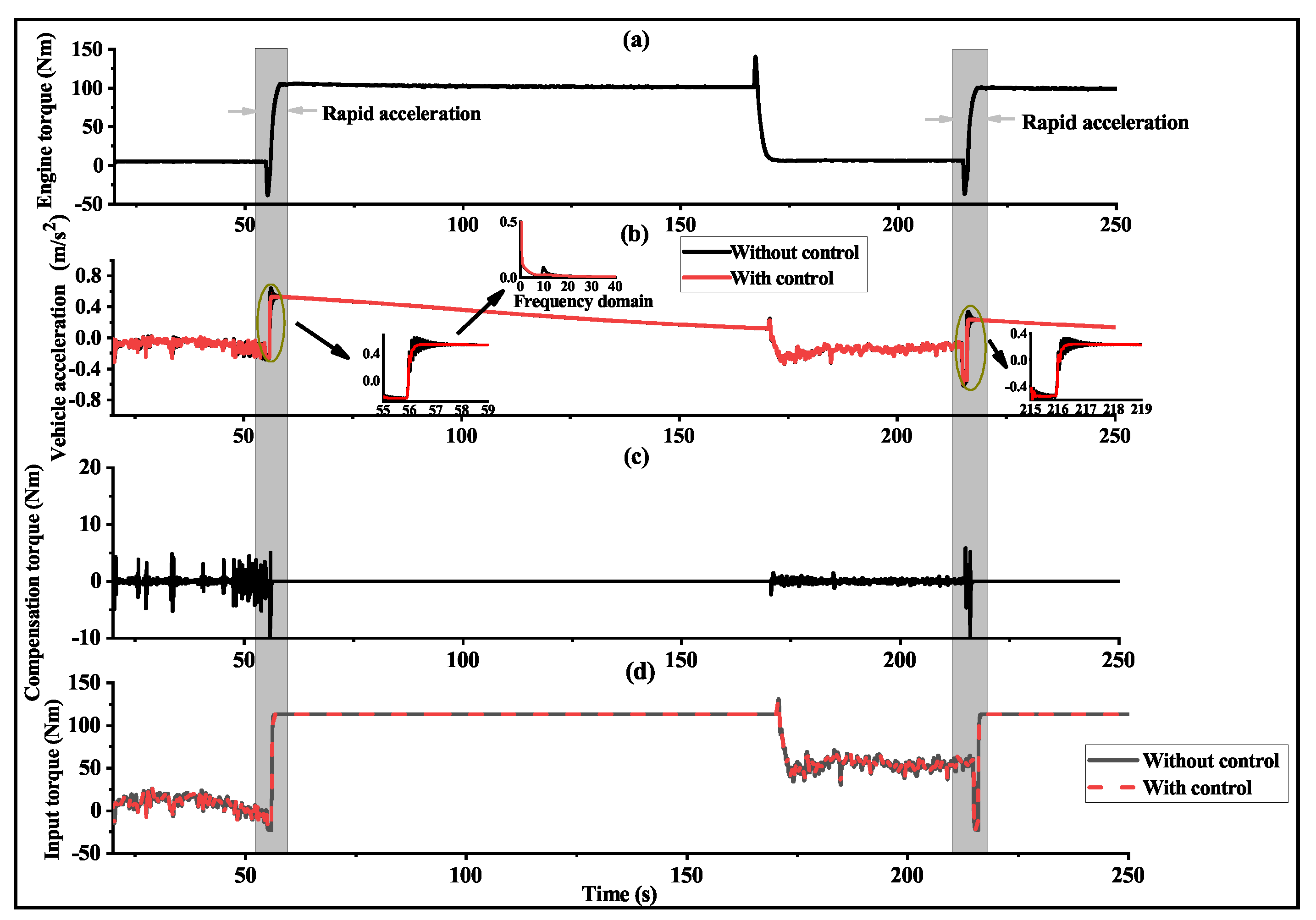
In order to further evaluate the proposed control scheme, a rapid acceleration was performed, and the corresponding control and observation results are presented in Figure 9 and Figure 10, respectively. To clearly demonstrate the oscillation damping performance, the amplitude spectrum of the corresponding vehicle acceleration was included in Figure 9b. The rapid acceleration test involved a sharp increase in engine torque from 5 Nm to 100 Nm within a duration of 2 s. The results in Figure 9 indicate that the acceleration process led to driveline oscillation in the absence of torque compensation. However, the proposed controller can effectively reduce driveline oscillation, which is clearly observed in the time and frequency domains.
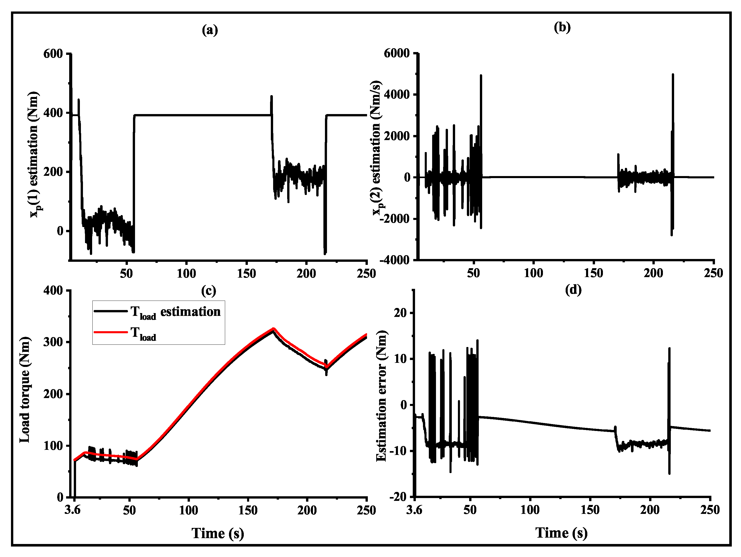
The performance of the extended state observer during the rapid acceleration scenario is shown in Figure 10, which presents the estimated body torque, change rate of the body torque, load torque, and the estimation error of the load torque. The load torque shows a stepwise increasing trend because it is related to the slope and air resistance. The load torque increases when the vehicle acceleration is greater than 0, with larger accelerations leading to faster increases. Conversely, the load torque decreases when the acceleration is less than 0, with smaller accelerations leading to faster decreases. The designed extended state observer exhibited excellent observation performance similar to the simulation results. The estimation error of the load torque demonstrated fast convergence with a steady-state error deviation of less than 10 Nm after convergence.
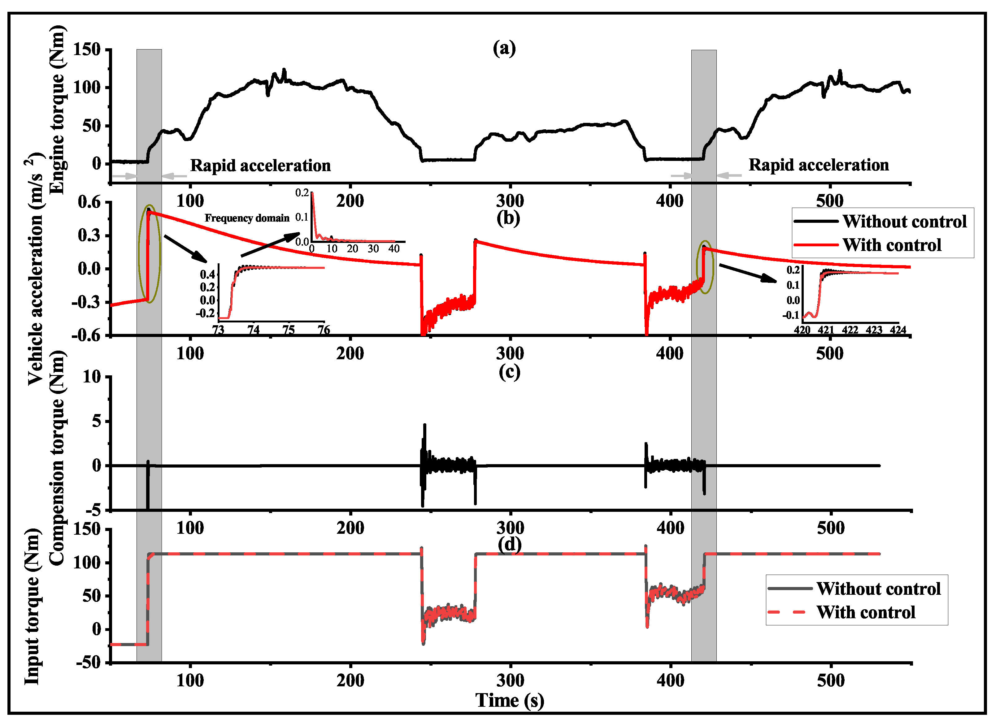
Apart from the rapid acceleration scenario, the proposed control scheme was evaluated under urban driving conditions using the traditional urban dynamometer driving schedule (UDDS). Figure 11 and Figure 12 illustrate the experimental results of the control and observation performance, respectively. Figure 12 presents observation performance for the proposed extended state observer. The results in the frequency domain are presented in Figure 11b. During the UDDS driving cycle, the engine torque increased from 3 Nm to 40 Nm within 2 s. The proposed observer-based compensator demonstrated ideal control and observation performance during the urban driving conditions.

5.2. Robustness Analysis for Parameter Mismatch

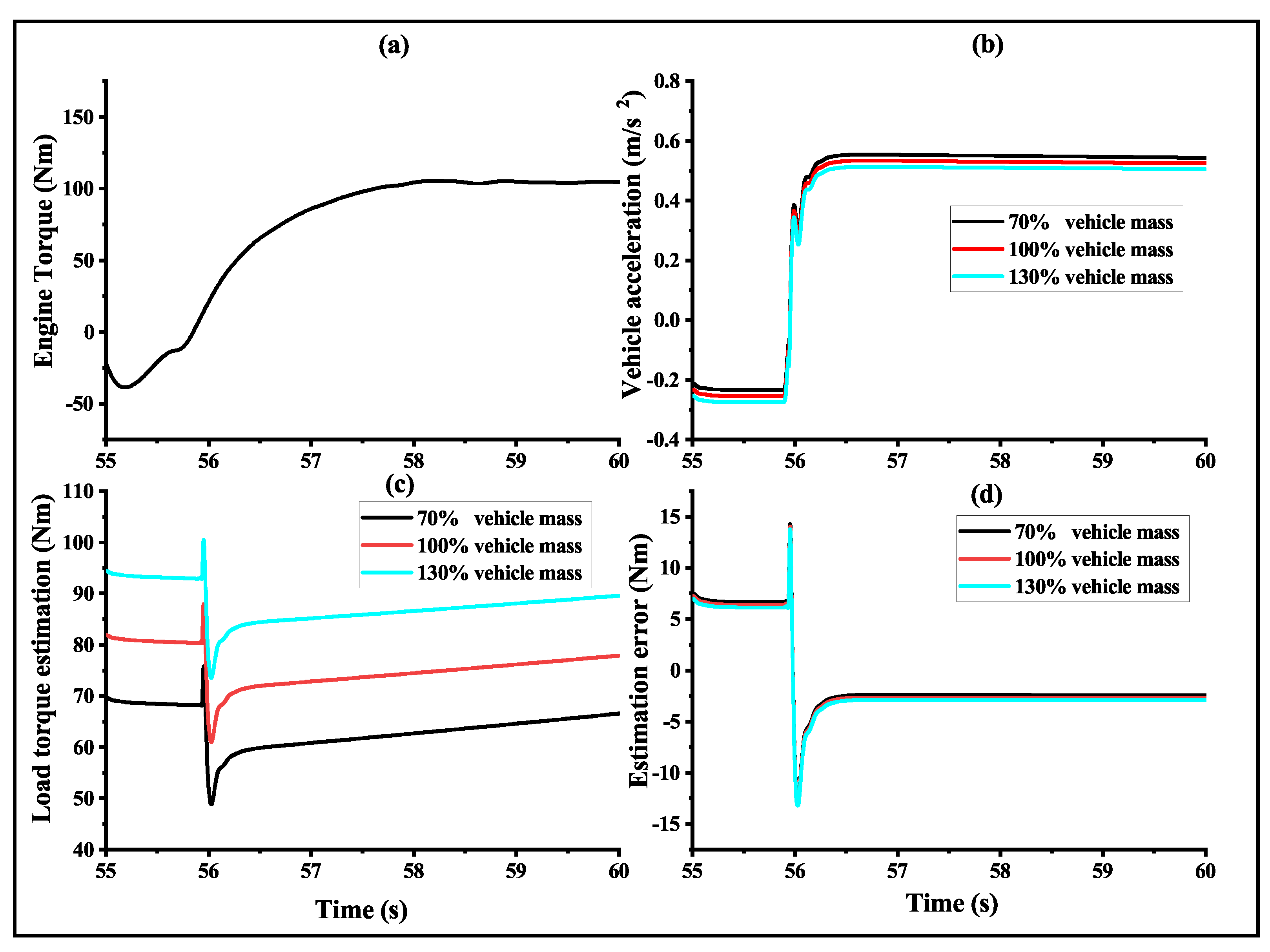
In practical control systems, the model of the controlled object often exhibits a certain degree of parameter mismatch. Variations in the weight of passengers or cargo within a vehicle can result in fluctuations in the model of the controlled system, consequently impacting the performance of the extended state observer. Therefore, the robustness of the designed extended state observer to variations in vehicle mass was evaluated under the same test scenario of Figure 9.
In the experiments, the vehicle mass was changed to 70%, 100%, and 130% of the original value, and the corresponding observation results are shown in Figure 13. Figure 13a is a segment extracted from the engine torque data during the rapid acceleration scenario. Figure 13b shows the variation in vehicle acceleration under the three different vehicle mass conditions. The acceleration decreased as the vehicle mass increased, due to the effect of inertia. However, the overall trend of the acceleration remained the same across all three conditions. Figure 13c illustrates the impact of different vehicle masses on load torque estimation, and Figure 13d is the load torque estimation error. The estimated load torque increased with the vehicle mass because the former is related to slope and air resistance. With other parameters held constant, a higher vehicle mass resulted in greater load torque. Again, the trend of the three conditions was the same. In general, the figure illustrates that the estimation errors remained consistent across different vehicle masses with a steady-state error deviation of less than 5 Nm after convergence. This finding demonstrates that the proposed extended state observer exhibited robustness against the considered model uncertainties.

6. Conclusions

Ensuring the effective suppression of driveline oscillation is crucial for promoting the sustainability of HEVs. The two primary challenges to address when damping driveline oscillation are the presence of time-varying torque load and nonlinear driveline backlash. Despite the fact that several active control methods have been proposed to address these challenges, certain issues, such as the requirement of a high-order model and the assumption of a known torque load, remain unresolved. In response to these challenges, the present study proposed an extended-state-observer-based compensator to actively suppress driveline oscillation in HEVs. The driveline model was simplified, for ease of controller design, as a second-order system with a dead zone. Subsequently, the compensator was designed using the method of pole allocation. An extended state observer was designed in order to estimate the state variables and load torque, and the input-to-state stability with respect to bounded model deviation was analyzed for the observer. Finally, simulation and engine-in-loop experiments were conducted in order to evaluate the control and observation performance of the proposed control scheme. The designed observer exhibited fast convergence performance and robustness against the considered model uncertainties, whereas the proposed control scheme significantly reduced driveline oscillation.
In our study, a fixed feedback gain was selected for the damping system and operating conditions. Nevertheless, investigating how the performance of the system would be affected if the feedback gain varied for different damping systems and operating conditions would be valuable. To this end, future research could focus on exploring the potential of adaptive control strategies that can adjust the feedback gain in real-time based on the performance of the system. Furthermore, additional research on the option value of electrified transportation is necessary in order to enhance its sustainability.

Author Contributions

Conceptualization, H.C., Y.J. and B.G.; methodology, H.C.; software, H.C. and W.S.; validation, H.C., W.S. and Y.J.; formal analysis, H.C. and Y.J.; investigation, H.C.; resources, H.C.; data curation, W.S.; writing—original draft preparation, H.C.; writing—review and editing, H.C., W.S. and Y.J.; visualization, W.S.; supervision, B.G.; project administration, H.C.; funding acquisition, H.C., Y.J. and B.G. All authors have read and agreed to the published version of the manuscript.

Funding

This work was supported in part by the Starting Research Fund from Shanghai Customs College (kyqd202204), by the International Technology Cooperation Program of the Science and Technology Commission of Shanghai Municipality (21160710600), by the Foundation of the State Key Laboratory of Automotive Simulation and Control, and by the Fundamental Research Funds for the Central Universities.

Institutional Review Board Statement

Not applicable.

Informed Consent Statement

Not applicable.

Data Availability Statement

Not applicable.

Conflicts of Interest

The authors declare no conflict of interest.

References

  1. Borozan, S.; Giannelos, S.; Strbac, G. Strategic network expansion planning with electric vehicle smart charging concepts as investment options. Adv. Appl. Energy 2022, 5, 100077. [Google Scholar] [CrossRef]
  2. Giannelos, S.; Borozan, S.; Strbac, G. A Backwards Induction Framework for Quantifying the Option Value of Smart Charging of Electric Vehicles and the Risk of Stranded Assets under Uncertainty. Energies 2022, 15, 3334. [Google Scholar] [CrossRef]
  3. Ou, S.; Hao, X.; Lin, Z.; Wang, H.; Bouchard, J.; He, X.; Przesmitzki, S.; Wu, Z.; Zheng, J.; Lv, R.; et al. Light-duty plug-in electric vehicles in China: An overview on the market and its comparisons to the United States. Renew. Sustain. Energy Rev. 2019, 112, 747–761. [Google Scholar] [CrossRef]
  4. Templin, P.; Egardt, B. A powertrain LQR-torque compensator with backlash handling. Oil Gas Sci. Technol. D’IFP Energies Nouv. 2011, 66, 645–654. [Google Scholar] [CrossRef]
  5. Awadallah, M.; Tawadros, P.; Walker, P.; Zhang, N. Dynamic modelling and simulation of a manual transmission based mild hybrid vehicle. Mech. Mach. Theory 2017, 112, 218–239. [Google Scholar] [CrossRef]
  6. Amann, N.; Bocker, J.; Prenner, F. Active damping of drive train oscillations for an electrically driven vehicle. IEEE/ASME Trans. Mechatronics 2004, 9, 697–700. [Google Scholar] [CrossRef]
  7. Zhang, J.; Chai, B.; Lu, X. Active oscillation control of electric vehicles with two-speed transmission considering nonlinear backlash. Proc. Inst. Mech. Eng. Part K J. Multi-Body Dyn. 2020, 234, 116–133. [Google Scholar] [CrossRef]
  8. Walker, P.D.; Zhang, N. Active damping of transient vibration in dual clutch transmission equipped powertrains: A comparison of conventional and hybrid electric vehicles. Mech. Mach. Theory 2014, 77, 1–12. [Google Scholar] [CrossRef]
  9. Tang, X.; Hu, X.; Yang, W.; Yu, H. Novel torsional vibration modeling and assessment of a power-split hybrid electric vehicle equipped with a dual-mass flywheel. IEEE Trans. Veh. Technol. 2017, 67, 1990–2000. [Google Scholar] [CrossRef]
  10. Qin, Y.; Tang, X.; Jia, T.; Duan, Z.; Zhang, J.; Li, Y.; Zheng, L. Noise and vibration suppression in hybrid electric vehicles: State of the art and challenges. Renew. Sustain. Energy Rev. 2020, 124, 109782. [Google Scholar] [CrossRef]
  11. Haris, A.; Motato, E.; Theodossiades, S.; Rahnejat, H.; Kelly, P.; Vakakis, A.; Bergman, L.A.; McFarland, D.M. A study on torsional vibration attenuation in automotive drivetrains using absorbers with smooth and non-smooth nonlinearities. Appl. Math. Model. 2017, 46, 674–690. [Google Scholar] [CrossRef]
  12. Kang, H.; Chung, T.; Lee, H.; Ihm, H. Active booming noise control for hybrid vehicles. SAE Int. J. Passeng. Cars-Mech. Syst. 2016, 9, 167–174. [Google Scholar] [CrossRef]
  13. Syed, F.U.; Kuang, M.L.; Ying, H. Active damping wheel-torque control system to reduce driveline oscillations in a power-split hybrid electric vehicle. IEEE Trans. Veh. Technol. 2009, 58, 4769–4785. [Google Scholar] [CrossRef]
  14. Song, D.; Yang, D.; Zeng, X.; Wang, Z. Active damping control strategy for a parallel hybrid electric vehicle based on model predictive control. Trans. Inst. Meas. Control 2023, 45, 120–132. [Google Scholar] [CrossRef]
  15. Hao, D.; Zhao, C.; Huang, Y.; Dai, P.; Liu, Y. Double-target switching control of vehicle longitudinal low-frequency vibration based on fuzzy logic. Shock Vib. 2018, 2018, 1–11. [Google Scholar] [CrossRef]
  16. Cauet, S.; Coirault, P.; Njeh, M. Diesel engine torque ripple reduction through LPV control in hybrid electric vehicle powertrain: Experimental results. Control Eng. Pract. 2013, 21, 1830–1840. [Google Scholar] [CrossRef]
  17. Fredriksson, J.; Weiefors, H.; Egardt, B. Powertrain control for active damping of driveline oscillations. Veh. Syst. Dyn. 2002, 37, 359–376. [Google Scholar] [CrossRef]
  18. Yonezawa, H.; Yonezawa, A.; Hatano, T.; Hiramatsu, S.; Nishidome, C.; Kajiwara, I. Fuzzy-reasoning-based robust vibration controller for drivetrain mechanism with various control input updating timings. Mech. Mach. Theory 2022, 175, 104957. [Google Scholar] [CrossRef]
  19. Chen, J.S.; Hwang, H.Y. Engine automatic start–stop dynamic analysis and vibration reduction for a two-mode hybrid vehicle. Proc. Inst. Mech. Eng. Part D J. Automob. Eng. 2013, 227, 1303–1312. [Google Scholar] [CrossRef]
  20. Ebrahimi, S.; Eberhard, P. Rigid-elastic modeling of meshing gear wheels in multibody systems. Multibody Syst. Dyn. 2006, 16, 55–71. [Google Scholar] [CrossRef]
  21. Ruderman, M. Optimal nonlinear damping control of second-order systems. J. Frankl. Inst. 2021, 358, 4292–4302. [Google Scholar] [CrossRef]
  22. Kautsky, J.; Nichols, N.K.; Van Dooren, P. Robust pole assignment in linear state feedback. Int. J. Control 1985, 41, 1129–1155. [Google Scholar] [CrossRef]
  23. Krstic, M.; Kokotovic, P.V.; Kanellakopoulos, I. Nonlinear and Adaptive Control Design; John Wiley & Sons, Inc.: Hoboken, NJ, USA, 1995. [Google Scholar]
  24. Chu, H.; Shi, H.; Jiang, Y.; Shen, T. Modeling of engine thermal dynamics and its application in energy management of HEVs considering engine warming-up. Int. J. Engine Res. 2023, 24, 147–160. [Google Scholar] [CrossRef]
Figure 1. Driveline configuration of HEV.
Sustainability 15 08143 g001
Figure 2. Simplified model from input torque T op to traction torque T body .
Sustainability 15 08143 g002
Figure 3. Diagram of the extended-state-observer-based control scheme.
Sustainability 15 08143 g003
Figure 4. Oscillation damping performance for different controllers. (a) Time-domain and frequency-domain results of vehicle acceleration. (b) Compensation torque. (c) Driveshaft input torque.
Sustainability 15 08143 g004
Figure 5. Observation performance for the proposed extended state observer. (a) Estimated body torque. (b) Change rate of body torque. (c) Load torque. (d) Estimation error of load torque.
Sustainability 15 08143 g005
Figure 6. Observation performance comparison for the proposed extended state observer and Luenberger state observer. (a) Body torque observed by Luenberger state observer. (b) Body rotation speed observed by Luenberger state observer. (c) Body torque observed by extended state observer. (d) Body rotation speed by extended state observer. (e) Observation error of body torque. (f) Observation error of body rotation speed.
Sustainability 15 08143 g006
Figure 7. Observer results for different initial state values: estimation error is ( ω body ω ^ body ) .
Sustainability 15 08143 g007
Figure 8. Engine-in-loop experimental platform.
Sustainability 15 08143 g008
Figure 9. Oscillation damping performance for the observer-based controller: rapid acceleration. (a) Engine torque. (b) The overall variation process of vehicle acceleration and the zoomed-in magnified views for two rapid acceleration segments. (c) Compensation torque. (d) Driveshaft input torque.
Sustainability 15 08143 g009
Figure 10. Observation performance for the proposed extended state observer: rapid acceleration. (a) Estimated body torque. (b) Change rate of body torque. (c) Load torque. (d) Estimation error of load torque.
Sustainability 15 08143 g010
Figure 11. Oscillation damping performance for the observer-based controller: UDDS cycle. (a) Engine torque. (b) The overall variation process of vehicle acceleration and the zoomed-in magnified views for two rapid acceleration segments. (c) Compensation torque. (d) Driveshaft input torque.
Sustainability 15 08143 g011
Figure 12. Observation performance for the proposed extended state observer: UDDS cycle. (a) Estimated body torque. (b) Change rate of body torque. (c) Load torque. (d) Estimation error of load torque.
Sustainability 15 08143 g012
Figure 13. Robustness against parameter mismatch of the vehicle mass. (a) A segment extracted from the engine torque data during the rapid acceleration scenario. (b) Vehicle acceleration. (c) Load torque estimation. (d) Load torque estimation error.
Sustainability 15 08143 g013
Disclaimer/Publisher’s Note: The statements, opinions and data contained in all publications are solely those of the individual author(s) and contributor(s) and not of MDPI and/or the editor(s). MDPI and/or the editor(s) disclaim responsibility for any injury to people or property resulting from any ideas, methods, instructions or products referred to in the content.