1. Introduction
Pepper is one of the most important cash crops, which enjoys a wide range of applications. China is a major producer and consumer of pepper [
1]. Currently, the extensive cultivation of pepper in China has posed a serious challenge to the traditional methods of artificial harvesting. In fact, the method commonly adopted in most areas under the background of large area planting easily causes high labor costs, high labor intensity, and low production efficiency [
2], greatly affecting the stable supply and operation of the industrial pepper production chain. Therefore, it is important to realize mechanized pepper harvesting as soon as possible.
The crawler pepper harvester is suitable for ridge tillage of small fields in hilly areas. In this mode, the vibration response of the chassis and frame is significantly influenced by poor road conditions. Moreover, the pepper harvester usually undertakes the functions of picking, transportation, cleaning and separation during operation, which requires sufficiently fine working parts and a complex excitation source. The reason is that the unreasonable and unstable frame structure of the chassis easily contributes to violent vibration. Violent vibration brings the following two problems: (1) according to statistics, 80% of structural failure belongs to fatigue failure, and 75% of fatigue failure is related to vibration. Therefore, severe vibration tends to cause serious structural damage, which not only affects the service life of pepper harvesters, but also increases maintenance and repair costs, thus generating a certain degree of waste of resources. (2) Violent vibration causes strong friction between components. In order to overcome the resistance brought by friction, more energy needs to be consumed, resulting in increased fuel consumption. This suggests that vibration is a key issue in the development of pepper harvesters towards energy conservation and comfort.
At present, a number of scholars have studied the vibration characteristics of agricultural machinery from different aspects [
3,
4,
5], mainly focusing on the analysis of the vibration and comfort of the driver’s seat, the modal analysis of the chassis frame, the establishment of the vibration model, the vibration and noise of the fan and so on [
6,
7,
8,
9,
10,
11,
12,
13,
14,
15]. In order to reduce the resonance risk of combine harvesters, through carrying out a modal analysis and modal test on the cutting platform frame, Li et al. [
16] solved the natural frequency of the cutting platform frame, and successfully avoided the external excitation frequency by structure optimization, achieving the effect of vibration reduction and weight reduction. Bulent et al. [
17] surveyed the vibration conditions of olive harvesters during working and proposed vibration reduction measures based on a structural counterweight. Pezzi and Caprara [
18] studied the effects of the vibration frequency of grape harvesters on vibration intensity, yield and quality of harvested grapes, and optimized the yield and quality level of grapes through frequency regulation.
In order to explore the resonance of the frame, most of the above studies focused on the vibration characteristics of each working part, while the vibration characteristics of harvesters in the field working condition are rarely investigated. The harvester works in the field for a long time, with many working parts and a complex vibration. The rotational speed of the engine and working parts, as well as the field pavement excitation, are all important factors that affect the vibration characteristics of harvesters.
In this paper, taking the structural characteristics, chassis frame and main vibration sources of a 4JZ-1700 crawler pepper harvester as the research object, the vibration characteristics of each measuring point in each working condition were tested and studied. The measurements were combined with the data from theoretical analysis to determine the effects of the engine and working parts speed and field pavement excitation on the vibration of the harvester, which can provide reference data and practical value for the vibration reduction optimization of pepper harvesters. Through vibration reduction optimization, the development of tracked pepper harvesters towards energy conservation and comfort can be further promoted.
2. Materials and Methods
2.1. Structure and Working Principle of Pepper Harvester
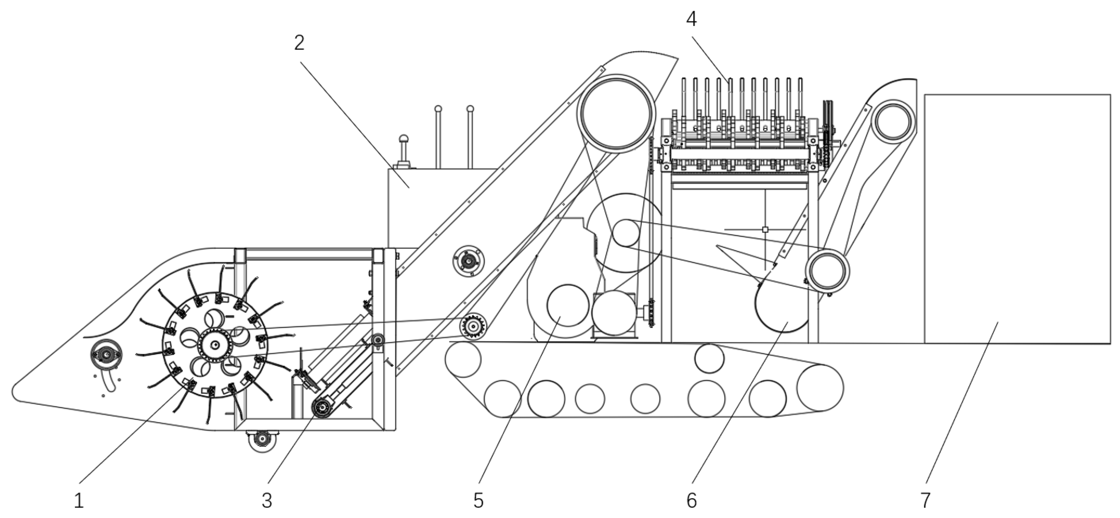
The 4JZ-1700 crawler pepper harvester is shown in
Figure 1. When working in the field, the picking device drives the spring finger of the roller to pull the peppers down along with the stem, branches and leaves, and then sends them to the cleaning separation device through the primary lift. The driving shaft of the cleaning separation device drives the star-shaped wheel to work through the sprocket. The spacing of the star-shaped wheel is determined according to the stalk length of peppers. Therefore, the cleaning separation device can leak peppers into the secondary lift. The stems and leaves are discharged from the harvester by the star-shaped wheel, and the peppers are transported to the grain bin through the secondary lift.
2.2. Structure Diagram of Pepper Harvester
The main vibration sources of the pepper harvester include the engine, picking roller and cleaning separation device. The engine rpm (Revolutions Per minute, r/min) during operation is 1500 r/min. In order to understand the vibration frequency of each main vibration source, the tachometer was employed to measure the rpm of the main working parts, and then the theoretical vibration frequency was calculated by Formula (1) [
19]. The calculation results are summarized in
Table 1. Considering the test object is a vertical four-cylinder four-stroke diesel engine with two vibration orders, Formula (2) was used for calculating the vibration frequency. The rotational speed is 1500 r/min under the condition of small throttle, and its second octave frequency is 50 Hz. The rotational speed is 2100 r/min under the condition of large throttle, and its second octave frequency is 70 Hz. Since this test was conducted under two conditions of large or small throttle, it was necessary to calculate the theoretical frequency of the engine under the two speeds as mentioned above.
In the formula, means the vibration frequency of the working component (Hz); refers to the speed of the working component (r/min); is the vibration frequency of the engine (Hz); is the engine speed (r/min) and indicates the number of engine cylinders.
2.3. Modal Analysis of Chassis Frame
Modal analysis is a dynamic analysis method used for machine structures and components in mechanical engineering. The ultimate purpose of modal analysis is to obtain the modal parameters of mechanical structures and components, which provides a theoretical basis for the analysis of vibration characteristics of mechanical structures and components.
The modal parameters of mechanical structures need to be calculated by vibration differential equation, as shown in Formula (3).
where
refers to the mass matrix of chassis frame;
is the structural damping matrix;
is the structural stiffness matrix;
represents the external excitation received by the system and
denotes the displacement vector of the system. The whole chassis frame of the pepper harvester is equipped with an underdamped system, with damping approximately regarded as 0, and the inherent properties are not affected by external forces. The vibration differential equation of the chassis frame system is given in Formula (4).
The general form of the solution of the equation is described in Formula (5).
Substitute equation 5 into equation 4:
where
represents the characteristic value of the system;
denotes the eigenvector corresponding to the eigenvalue;
indicates an imaginary number unit;
means the natural frequency obtained by the system, Hz;
is time, s and
is equal to
.
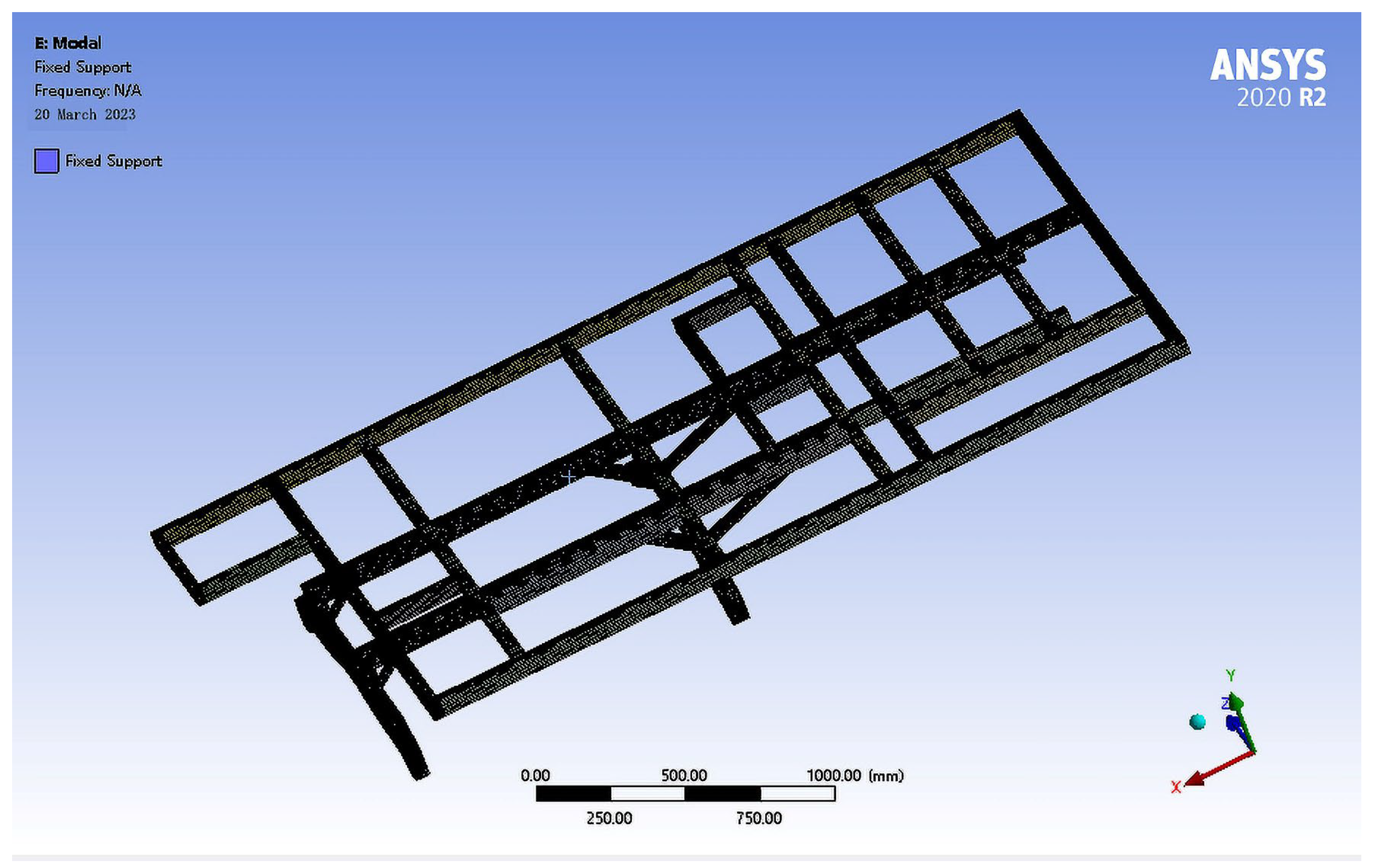
The above calculations were completed by the simulation software ANSYS. The three-dimensional model of the chassis frame of the pepper harvester was imported into ANSYS Workbench for modal analysis. The main material of the chassis frame was Q235 steel. The related parameters of the material were first determined, as shown in
Table 2.
Then, grid division was performed. The grid size is an important parameter for grid division, which determines the number and density of grid drawing. Excessively large grid size easily causes low computational accuracy issues. After multiple attempts, the grid size was finally set to 15 mm as the most appropriate. Automatic grid division is suitable for automatically identifying the entities that can be swept. For the entities that cannot be swept, their corresponding grid is divided by the ‘Patch confirming’ algorithm. In order to simulate the constraints of the chassis frame in actual work, the constraints are set at the connection between chassis frame and track. The finite element model is shown in
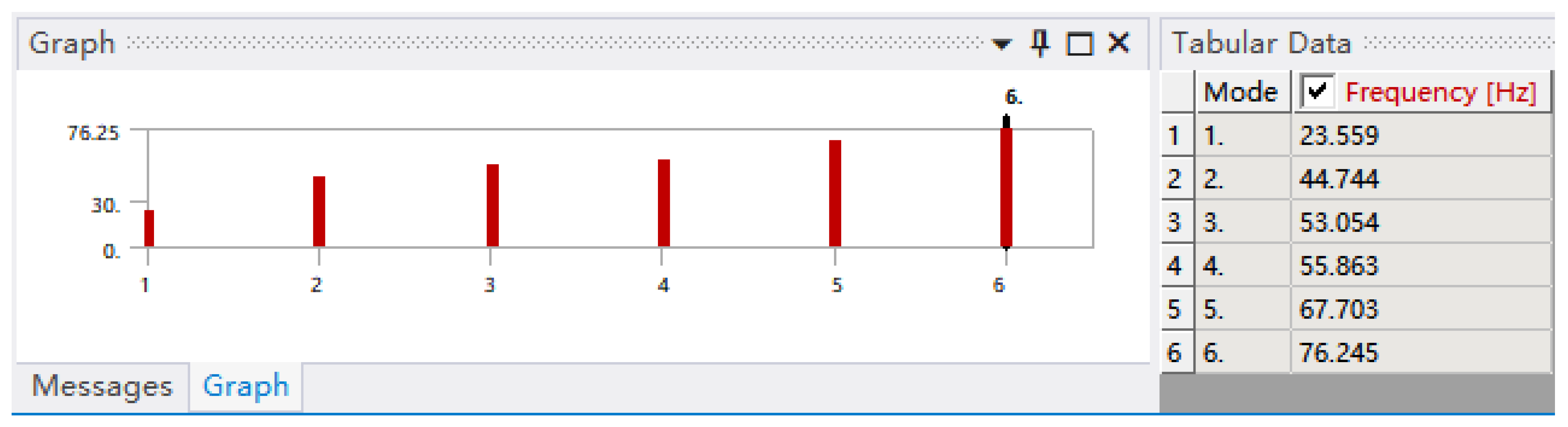
Figure 2. After the modal analysis preprocessing was completed, the first six natural frequencies of the chassis frame were solved, as provided in
Figure 3.
As shown in
Figure 3, the first six natural frequencies of the chassis frame are between 23–76 Hz, which can be used to compare the vibration frequencies of the main vibration sources of the pepper harvester, in order to determine whether there is resonance and vibration coupling.
2.4. Test Equipment and Parameters
The DH5902N robust data acquisition system produced by Donghua Testing Technology Co., LTD was used to test the vibration of the crawler pepper harvester under different working conditions. The main test equipment included a DH5902 robust dynamic signal acquisition instrument, 1A312E acceleration sensor and DHDAS dynamic signal acquisition and analysis system. The parameters of the test instrument are introduced in
Table 3. The vibration signal is received by the acceleration sensor and transmitted to the signal acquisition instrument. The dynamic signal acquisition instrument is connected with the dynamic signal acquisition and analysis system in the computer through the network cable. The vibration signal is manifested by the dynamic signal acquisition and analysis system.
2.5. Vibration Signal Acquisition
In this experiment, the chassis frame and main vibration sources of the 4JZ-1700K crawler pepper harvester were regarded as the research object to analyze the vibration characteristics of the chassis frame and each vibration source of the pepper harvester under working conditions. In order to simulate various states of harvesters working in the field, the experimental conditions were divided into idling conditions and field working conditions. Idle conditions were divided into two conditions: engine operation only and component operation, which could be further subdivided into large throttle and small throttle. Field working conditions were also divided into engine operation only and component operation. In order to facilitate subsequent data processing, the acceleration sensor installation should abide by the rules as follows: the X direction corresponds to the forward direction of the pepper harvester, the Y direction corresponds to the transverse direction of the pepper harvester, and the Z direction is perpendicular to the ground. The working conditions of the test are enumerated in
Table 4.
The test site was in Feng County, Xuzhou. The 4JZ-1700 crawler pepper harvester was tested under different working conditions in a two-mu pepper test field. The advance distance of the harvester in each test was 35 m, and the vibration data of 30 s was collected by the acquisition instrument in the test area. Before each test, the balanced zeroing operation of the whole system was carried out. Meanwhile, the throttle and working parts were controlled through the joystick. The measuring points were selected according to the structural characteristics of the pepper harvester. In essence, the measuring points are the main vibration source of the pepper harvester, which constitute the key nodes in the right front, left front, right back and left back positions of the chassis frame, aiming to receive the vibrations transmitted by most of the vibration sources. The selected measurement points are displayed in
Table 5.
2.6. Vibration Signal Processing
The vibration time domain signal was recorded by the DHDAS dynamic signal acquisition and analysis system. In engineering, the root mean square value of acceleration is generally adopted to reflect the magnitude and variation of the vibration amplitude of the crawler pepper harvester. In this paper, the root mean square value of acceleration was used to express the vibration intensity of the harvester. The calculation of the root mean square value is expressed by Formula (7) [
20]:
where
is the vibration signal and
denotes the average number.
Afterwards, the time domain signal was analyzed in the frequency domain. Frequency domain refers to the domain in which the function of variable frequency is located. Generally, an acceleration signal can be converted into the superposition result of trigonometric functions of different frequencies, namely Fourier transform. The conversion of discrete signals is expressed by Formula (8) [
21]:
where
represents discrete signal points;
indicates the number of sampling points and
is the analysis frequency.
3. Results
3.1. Time Domain Signal Analysis of Chassis Frame Vibration
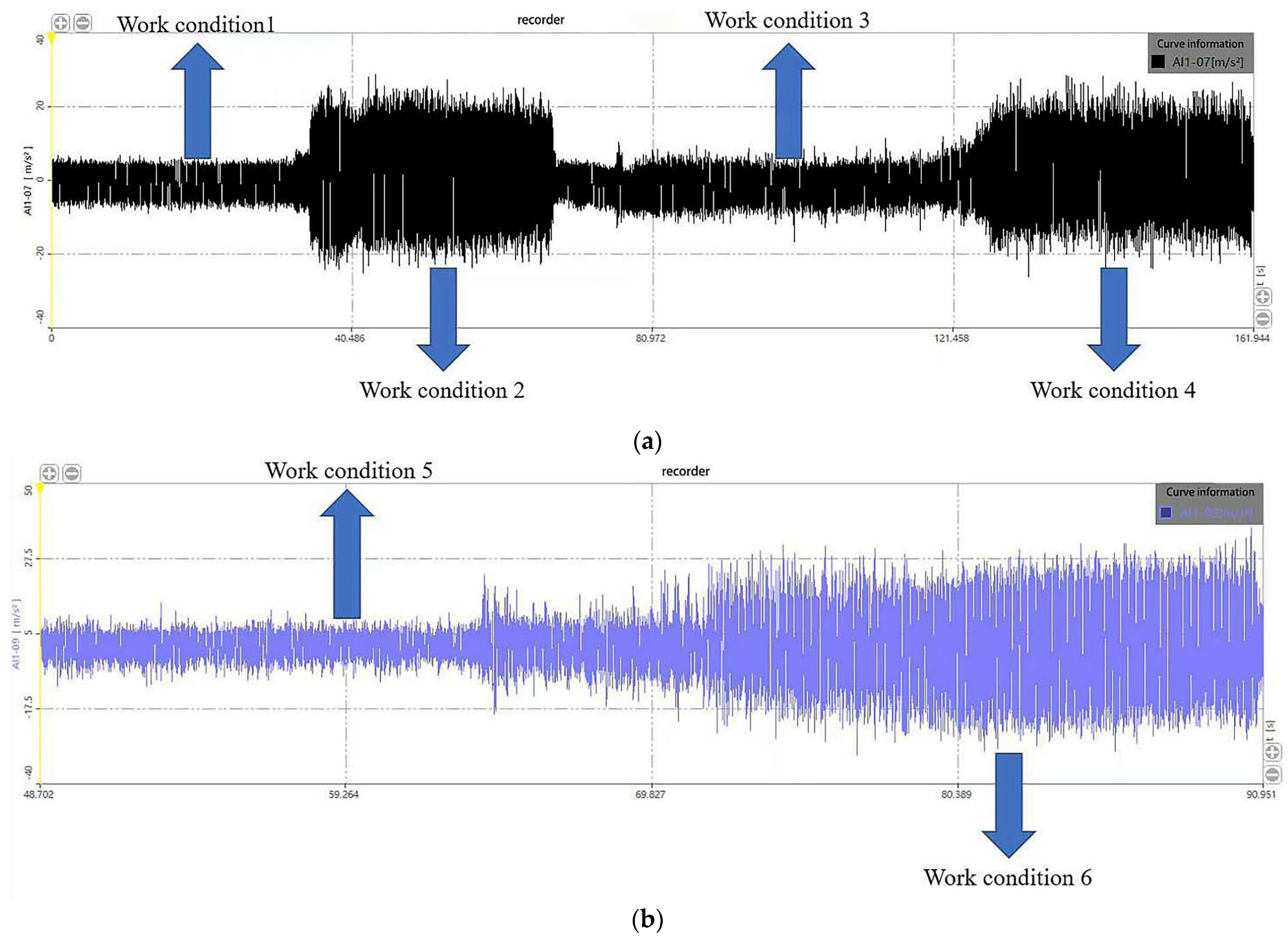
The vibration analysis of the pepper harvester under a single working condition can only partially reflect its vibration characteristics, which are different under different working conditions. Consequently, in order to compare the vibration characteristics of each vibration source under different working conditions, working conditions 1–4 were integrated into one group, and working conditions 5 and 6 were included into the other group. The two groups were tested separately. The sampling time of each working condition was about 35 s, so that the vibration characteristics of each working condition could be intuitively observed and compared. The general trend of time domain signals is presented in
Figure 4.
The root-mean-square values of acceleration in three directions under different working conditions at each measuring point are organized in
Table 6.
The root-mean-square acceleration value of total vibration at each measurement point can be calculated by Formula (9) [
20]:
where
indicates the root mean square value of acceleration of total vibration at each measurement point (m/s
2) and
refers to the root-mean-square value (m/s
2) of a measuring point in the direction
.
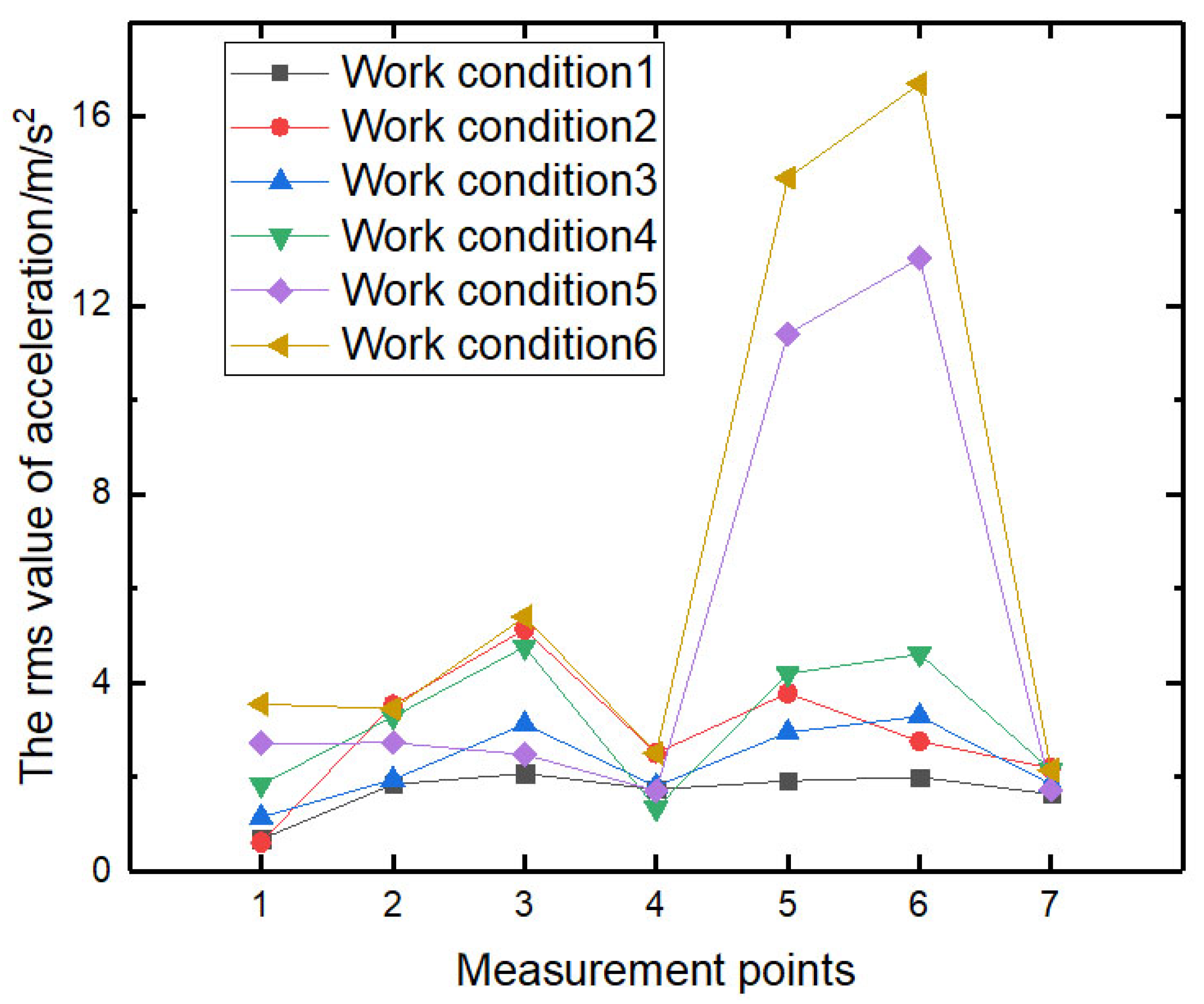
The total vibration diagram of each measuring point under different working conditions is shown in
Figure 5. When the harvester is in the working condition of static no-load small throttle, the amplitude at the engine support is relatively higher. Compared with the measuring point 6, the amplitude under working condition 1 is only 0.08
higher, and the amplitude under working condition 3 is even 0.17
lower. When the harvester is in the working condition of static no-load large throttle, the amplitude at the engine support is the highest. In addition, when the harvester is in the field working condition, the amplitude at the engine is obviously lower than some measuring points. The amplitude of measuring points 5 and 6 is obviously abnormal, and the root mean square of acceleration is greater than 10
, which may be due to the influence of field excitation and the high center of gravity of the cleaning separation device. In general, the total vibration of the pepper harvester was the highest in the field walking (component operation) condition, while the total vibration of the static no-load (only engine working, small throttle) condition was the lowest. This shows that the overall vibration of the harvester is more intense during the working process of the components.
3.2. Frequency Domain Characteristic Analysis of Chassis Frame
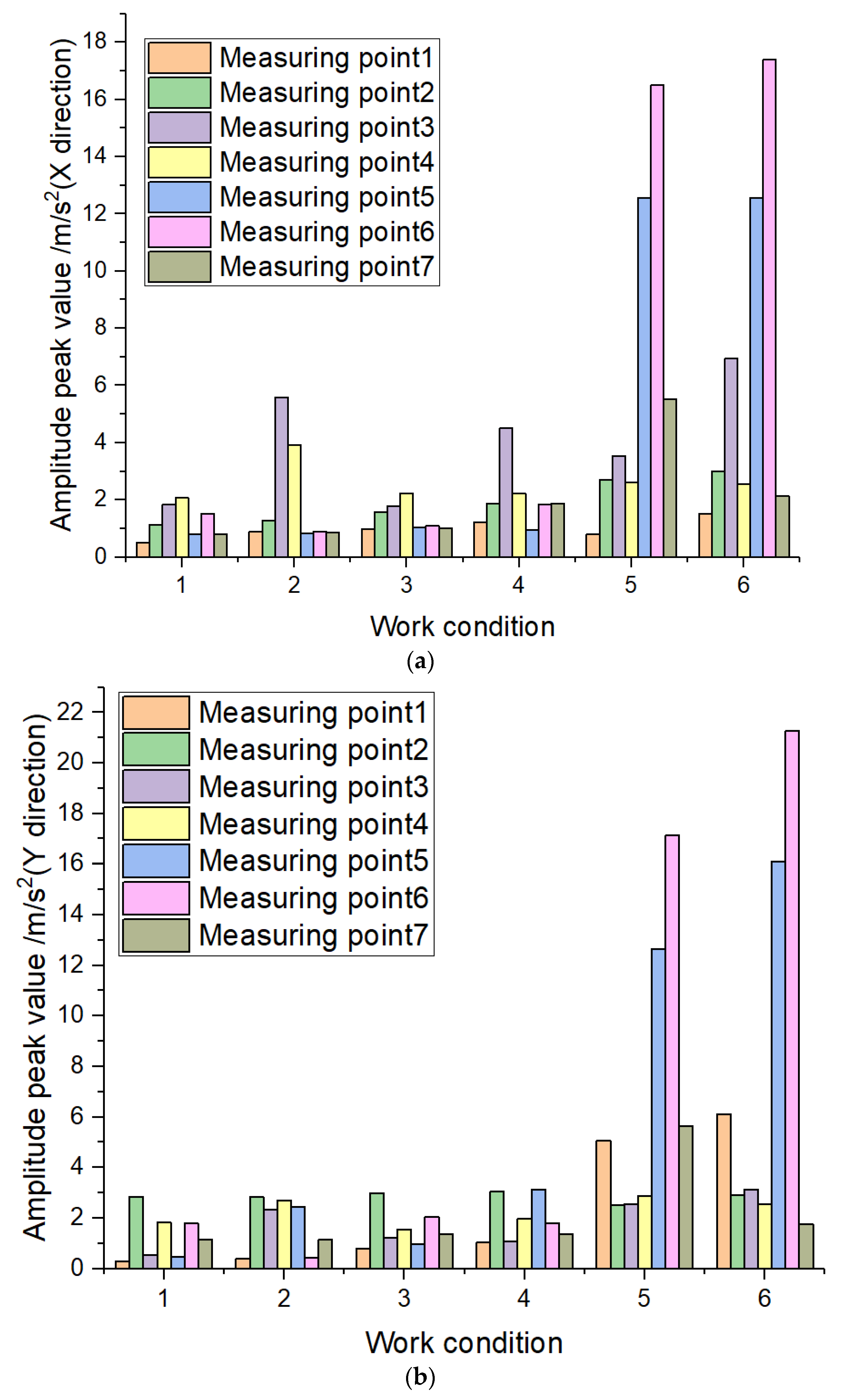
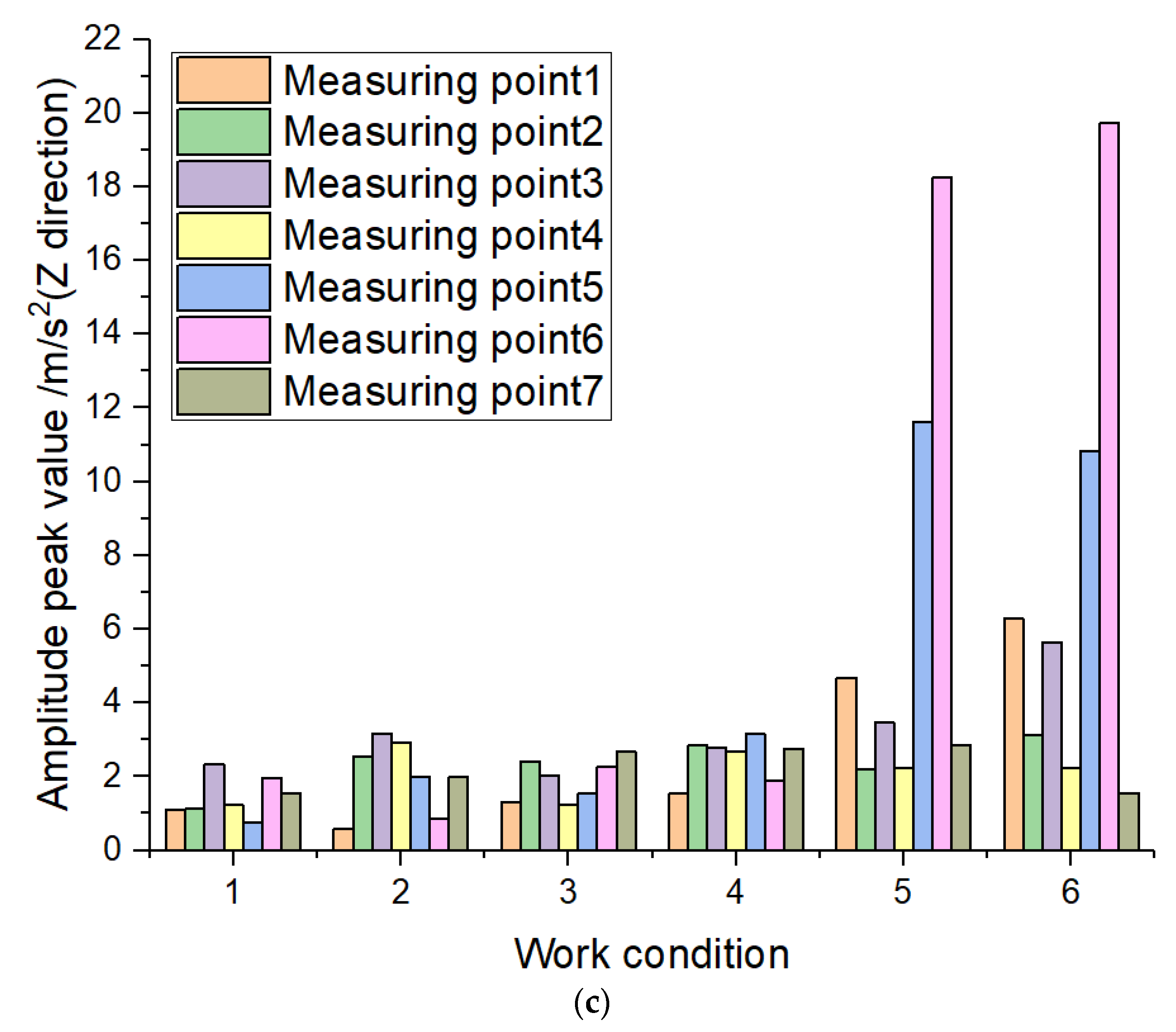
Fourier transform was performed on the vibration time-domain signal, and the amplitude peak value and peak frequency obtained in each working condition are displayed in
Figure 6 and
Figure 7. Clearly, the main frequency of the engine support under the condition of small throttle is close to the fundamental frequency (25 Hz) of the engine under 1500 r/min. The main frequency of engine support under the condition of large throttle approximates to the second frequency doubling (70 Hz) of engine at 2100 r/min.
It can be seen from
Figure 6 that the amplitude peaks in three directions at the engine support are the largest in the longitudinal direction, the second in the vertical direction and the smallest in the transverse direction under most working conditions. In general, the amplitude peak is small, and the vibration is relatively stable under the static no-load condition. However, the amplitude peak is larger, and the vibration is relatively severe under the field working condition.
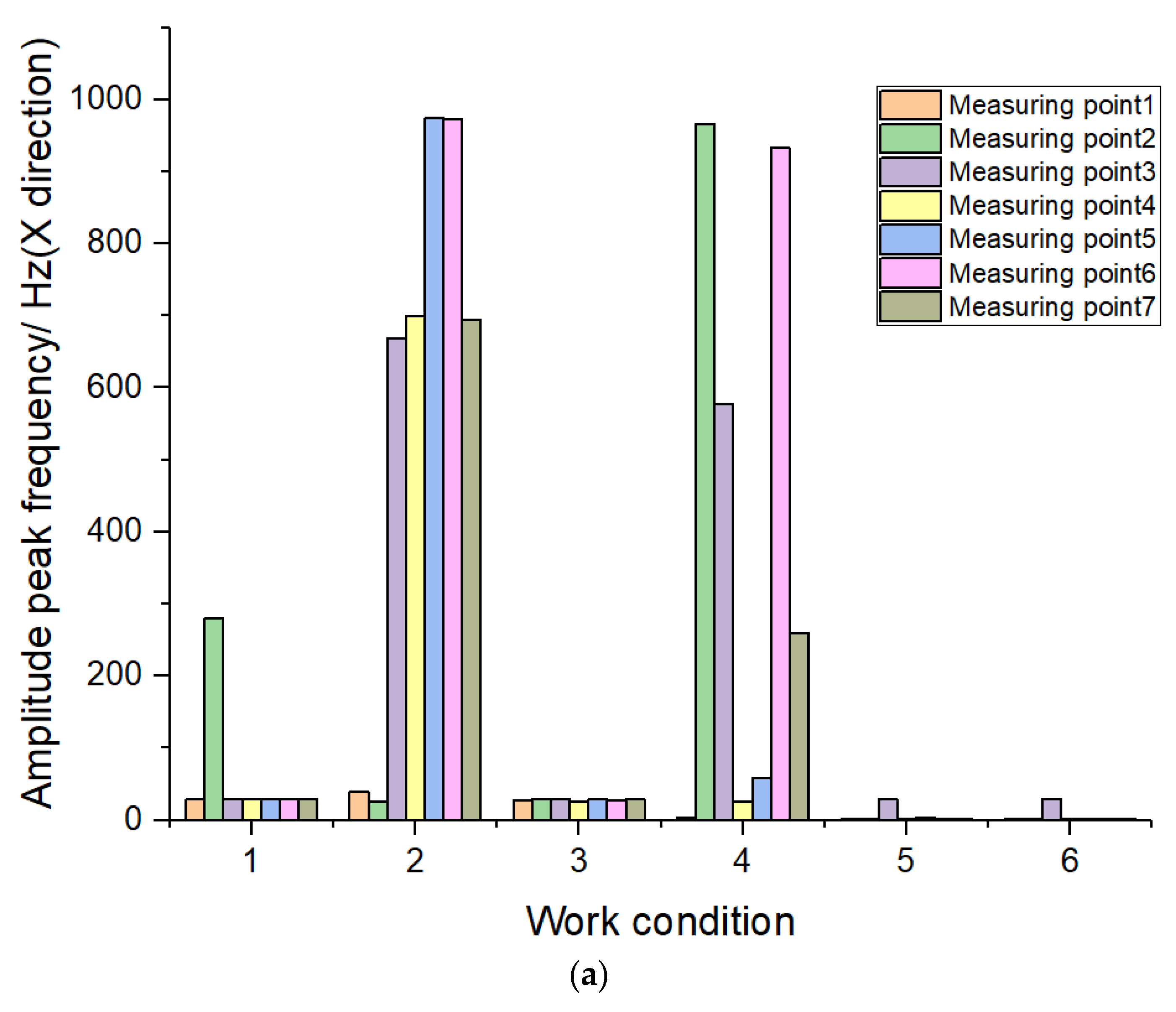
As can be seen from
Figure 7, most vibration frequencies under static no-load conditions with small throttle are 28.75 Hz, which is within the range of 23–76 Hz of the natural frequency of the chassis frame, mentioned in
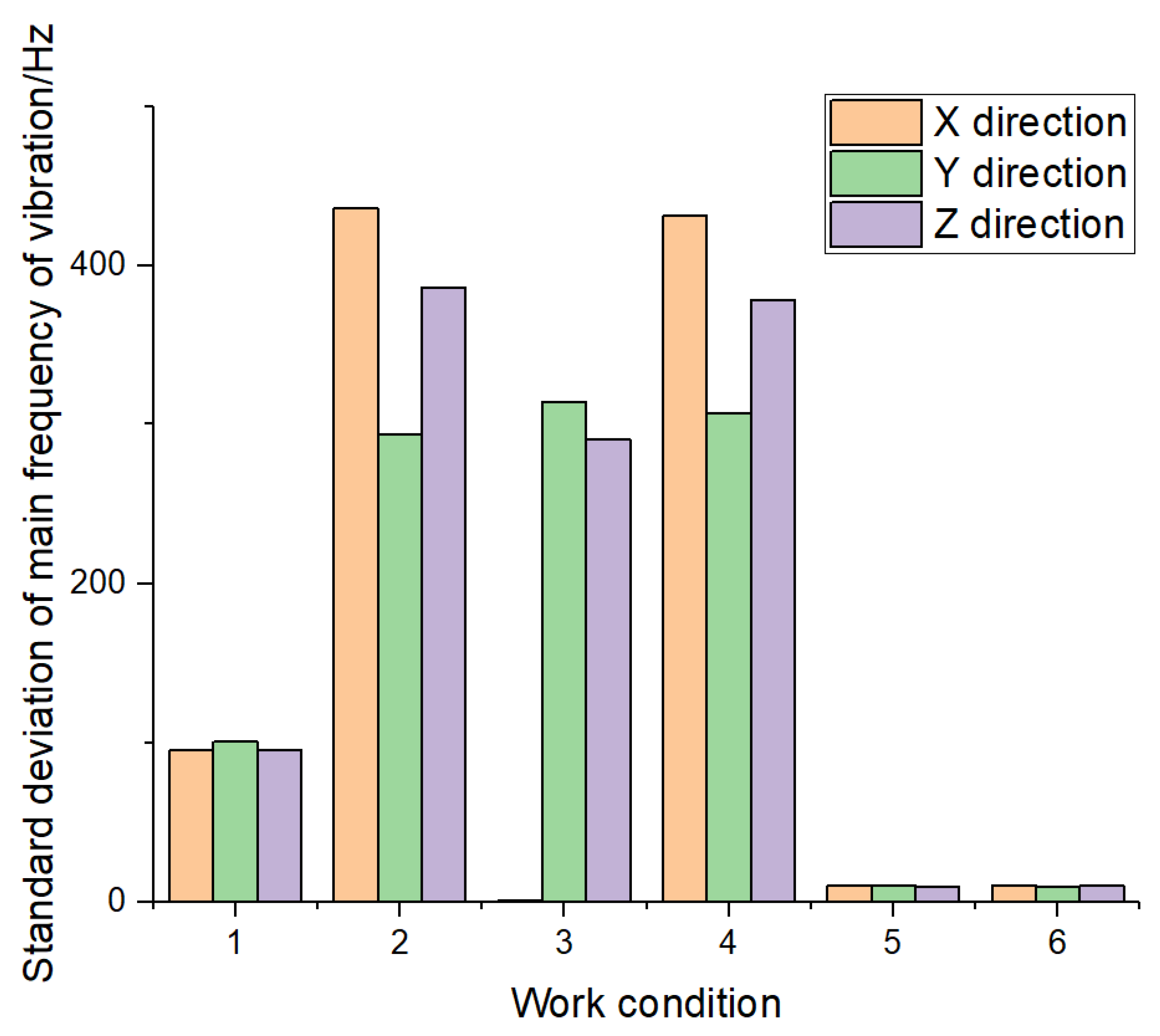
Section 2.4. Therefore, the chassis frame and all vibration sources are prone to resonate under this condition. The main frequency of vibration under the condition of static no-load and large throttle is mainly in the high frequency region and relatively disorderly. The main frequencies of vibration under the field working condition are mostly 1.25 Hz and 2.5 Hz, which are close to the theoretical working frequencies of the picking drum (3.58 Hz) and cleaning separation device (3.07 Hz). In addition, further standard deviation analysis was performed on the main frequency of vibration, as shown in
Figure 8.
As can be seen from
Figure 8, the standard deviation of the main frequency of vibration is the highest under the static no-load large throttle condition (working conditions 2 and 4), followed by the static no-load small throttle condition (working conditions 1 and 3), and the minimum in the field working condition. Combined with the analysis in
Figure 7, it is not difficult to observe that there is a relatively common resonance phenomenon in the condition of small throttle, which is also the reason for the large amplitude in this working condition.
4. Discussion
By analyzing the vibration amplitude in
Table 6 and
Figure 5, it can be found that the engine speed causes an effect on the amplitude, and a fast engine speed leads to a large amplitude of the chassis frame. The test results were basically consistent with those obtained by Yilmaz et al. [
22]. In this study, only the acceleration sensors were arranged on the concave plates on both sides of the harvester, and few studies have been conducted on the vibration characteristics of the main vibration sources. For this reason, this paper put emphasis on the exploration of the vibration characteristics of the main vibration sources. Moreover, the comparison of the amplitudes of each measuring point manifests that the amplitudes of the engine support and the drive shaft bearing seat of the cleaning separation device and the left front of the chassis frame of the cleaning separation device are relatively large under the static no-load condition, while the amplitudes of the drive shaft bearing seat of the cleaning separation device and the chassis frame are relatively large under the field working condition. According to the above analysis, in order to reduce the vibration of chassis frame, the following main vibration reduction measures are proposed by consideration of the aspects of the engine, the driving shaft bearing seat of the cleaning separation device as well as the left front of the chassis frame: (1) in terms of engine selection, Pang et al. [
23] studied the isolation effect of different vibration pads, pointing out that the damping pad with smaller stiffness contributes to better damping effect; that is, effectively blocking the vibration transmitted by the engine to the chassis frame. (2) The amplitude of the driving shaft bearing seat of the cleaning separation device is abnormal under the field working condition. The main reason is that the center of gravity of the cleaning separation device is extremely high, and the cleaning device is only fixed by four supporting beams, resulting in obviously insufficient structural strength. Therefore, on the premise of not affecting the working performance, it is suggested to reduce the height of each working part on the chassis frame, and weld the strengthening beam between the support beam and the chassis frame to form a triangular structure to increase the stability. (3) The amplitude at the left front of the chassis frame is abnormal, where the vibration is mainly transmitted by the cleaning separation device. In response to this problem, Chen et al. [
24] designed a suspension system containing a nylon friction damping device, obtaining a good vibration reduction effect. As a consequence, it is possible to follow this idea and install a damping device in the area where severe vibration of the chassis frame appears to block the vibration transmitted by the cleaning separation device, so as to achieve the effect of vibration reduction.
According to the analysis of the peak amplitude in
Figure 6, the peak amplitude of the engine is the largest in the longitudinal direction (X direction), which may be because the engine support is tilted, and the excitation force generated by the engine combustion is decomposed in the longitudinal direction (X direction). Generally speaking, the amplitude peak is the largest and the vibration is the most intense under the field working (component operation) condition. The amplitude peak is the smallest and the vibration is the least under the condition of static no-load small throttle (only engine). This shows that the vibration of the chassis frame can be increased by the excitation of working parts and uneven road surface. This conclusion was confirmed in a study by Tang et al. [
25], who proved that the vibration of the threshing process was more intense by comparing the amplitude of the no-load state and threshing process.
According to the analysis of the peak frequency in
Figure 7 and the standard deviation of the main frequency of vibration in
Figure 8, it can be seen that the main frequency of vibration is close to the working frequency of the engine under the condition of static no-load small throttle (working conditions 1 and 3). Most of the main frequencies of vibration approximate to the working frequencies of the picking drum and the cleaning separation device under field working conditions (working conditions 5 and 6). Resonance exists in both conditions. Resonance is one of the major causes of excessive amplitude in field working conditions. Nevertheless, a large number of high-frequency vibration phenomena are found in the static no-load large throttle condition, and there is no rule. This may be because of large friction between the bearing pedestal and the rotating shaft caused by insufficient lubrication, or loose screws, resulting in the instability of the working parts. Based on the above analysis, the following improvement measures are proposed: (1) the inclination angle of the engine support can be adjusted slightly to reduce the longitudinal vibration of the engine. (2) Lubricating oil should be added between the rotating shaft and the bearing seat of the working parts to decrease excessive friction between the two. (3) The natural frequency of the chassis frame is determined by the stiffness and mass. Ebrahimi et al. [
26] changed the natural frequency of the support through calculating the required variation in the mass of the cutting platform support, providing the possibility of getting away from the resonance region. Therefore, the chassis frame can be kept away from the resonance zone by changing the mass. (4) The speed adjustment of the main working parts and change of the working frequency can be achieved by modifying the diameter of the drive sprocket and belt wheel to change the transmission ratio.
5. Conclusions
(1) Through research and analysis, it can be concluded that the amplitude of the engine and the cleaning separation device is relatively large, and the vibration reduction optimization mainly concentrates on these two aspects. On this basis, the methods for reducing vibration include installing damping devices and improving the support structure.
(2) The amplitude peak of the engine in the longitudinal direction (X direction) is the largest under most working conditions, followed by the vertical direction (Z direction) and the horizontal direction (Y direction). The excitation force component in a certain direction can be reduced by adjusting the inclination angle of the engine support.
(3) General resonance is found to exist in the condition of small throttle and field working conditions, while there are a large number of high-frequency vibration phenomena in the large throttle condition. In view of this, the above problems are improved by adding lubricating oil, changing parameters that affect the natural frequency of chassis frame and adjusting the transmission ratio between components.
By studying the vibration characteristics of the chassis frame and the main vibration sources of the crawler pepper harvester, the structure and cause of its severe vibration are analyzed, and several improvement measures are put forward accordingly. This study provides a theoretical basis for the optimal design of crawler pepper harvesters, which not only can abate fatigue damage caused by severe vibration and repair and maintenance costs, but also reduce energy loss and enhance energy efficiency by decreasing vibration, so as to effectively cut down fuel consumption and save energy. At the same time, this study helps to support ideas for research into the vibration of other agricultural machinery, especially harvesting machinery. However, some deficiencies in this study still cannot be ignored. Subsequent research on such issues can be improved on this basis. In the future, more accurate and comprehensive analysis of the vibration characteristics of agricultural machinery, combined with increasingly optimal optimization methods, will contribute to the development and production of resource-saving agricultural machinery.


