Article

Flexural Capacity of Cross-Shaped Concrete-Filled Steel Tubular Column–Steel Beam Joints with Side-Plate Connections

1
School of Architecture and Civil Engineering, Zhongyuan University of Technology, Zhengzhou 450007, China
2
SIPPR Engineering Group Co., Ltd., Zhengzhou 450007, China
*
Author to whom correspondence should be addressed.
Sustainability 2023, 15(1), 541; https://doi.org/10.3390/su15010541
Submission received: 28 October 2022 / Revised: 19 December 2022 / Accepted: 22 December 2022 / Published: 28 December 2022

Abstract

:
The application of connection joints between a cross-shaped concrete filled steel tubular column and a steel beam can improve the seismic performance, which also provides an effective way for saving building space. In this paper, models and flexural capacity of the connection joint with and without side plates were designed and evaluated, respectively. A refined mechanical analysis model of a joint subjected to low-cycle reciprocating loading was established using the finite element software ABAQUS. The failure characteristics of the joints with and without side plates were compared. The influence of axial compression ratio, side plate height, and side plate thickness on the flexural capacity of joints with side plates was studied. Moreover, the failure mode and force transfer mechanisms of these joints were analyzed. Based on the results of the finite element analysis (FEA), the ultimate tensile capacity of the steel tube column flange to the steel beam was calculated according to the yield line theory; the tension transmitted by the side plate was simplified for calculation via the static equilibrium method. Subsequently, the formula for calculating the flexural capacity of the joint with side plates is established. The results show that the ultimate bearing capacity of the joint was increased by 41.5% due to side plates effect, which decreased with an increasing axial compression ratio. Moreover, the ultimate bearing capacity of the joints increase slightly with an increase of height and thickness of the side plate, and the maximum increase was only 6.2%. In addition, the calculated results obtained by the proposed formula of ultimate flexural capacity are consistent with the results of the FEA.

1. Introduction

Concrete-filled steel tubes (CFSTs) have been widely used in the construction of high-rise buildings because of their good mechanical properties [1,2,3,4,5,6,7,8]. In particular, columns with special shapes (e.g., the L-shaped section for corner columns, the T-shaped section for side columns, and cross-shaped sections for central columns) that have equal thickness of column limbs and infilled walls can avoid the defects of protruded beams and columns. Such columns are used to improve indoor space utilization, which can be beneficial for furniture arrangement and indoor decoration. Specially shaped concrete-filled steel tubular columns are produced by pouring concrete into these steel tubes. Because of the synergy between the steel tube and concrete, CFSTs have the advantages of high bearing capacity, good plasticity, improved seismic performance, convenience of construction, and they can help improve the space utilization inside a building [9,10,11]. Specially shaped concrete-filled steel tubular column–steel beam joints transfer forces in the frame structural system. Joints should have a simple structure to ensure easy construction and should transfer bending moments and shear forces safely and reliably. In the Northridge earthquake in the United States and the Great Hanshin earthquake in Japan, failure of steel column–beam joints occurred mainly at the lower flanges of steel beams, where brittle failure occurred because of the weak ductility of the rigid joints with welded or welded bolted connections [12]. It can be seen that the joints are in a complex stress state under the combined vertical and transverse loads. Therefore, to benefit the application of specially shaped concrete-filled steel tubular structures, it is important to investigate joint forms with reasonable forces between these columns and steel beams, especially in terms of the seismic performance of the joints.
Currently, specially shaped concrete-filled steel tube column–steel beam joints are mainly classified into three structural forms: external diaphragm joints, interior diaphragm joints, and vertical stiffener joints. External diaphragm joints have a distinct force transmission path, high bearing capacity, and great stiffness and show no adverse impact on the concrete casting in the tube. Xu [13,14] and Li [15] conducted a quasistatic test on four top-story exterior joint specimens, seven intermediate-story exterior joint specimens, and eight intermediate-story interior joint specimens, which were all external diaphragm specially shaped concrete-filled steel tube column–steel beams joints. The load–displacement curves under three failure modes (plastic hinge failure at beam ends, joint panel zone failure, and plastic hinge failure at column ends) were determined by changing the beam section sizes. Among them, the tests for specimens under plastic hinge failure at beam ends verified the reliability of the exterior joints that connect multicell concrete-filled steel tubular columns and H-shaped steel beam structures. According to the existing experimental results, rationally designed external diaphragm joints of specially shaped concrete-filled steel tube columns meet the design requirements of “strong column and weak beam” and “strong joint and weak component”. However, the limitation is that the external diaphragm occupies much space outside the column, compared to the concept that specially shaped columns can improve indoor architectural performance. Interior diaphragm joints are often applied in large square, rectangular, and circular concrete-filled steel tube columns and beams. For example, Xue [16] investigated the seismic performance of interior diaphragm joints connecting T-shaped concrete-filled steel tubular columns and steel beams subjected to low-cycle reciprocating loading. The results showed that the failure modes of the specimens were mainly shear failure in the joint panel zone and fracture at the beam ends. The hysteretic curves showed no remarkable pinching effect, revealing that joints had great energy dissipation capability. Li [17] conducted tests on five scaled joint specimens (scale ratio: 1/2) subjected to different loading schemes to investigate seismic damage to joints connecting cross-shaped concrete-filled steel tube columns with I-shaped steel beams. The findings were consistent with those of Xue [16]. In addition, research on the size of the opening hole of the interior diaphragm showed that the holes should not be greater than 50% of the column section width (or diameter) to ensure that the interior diaphragm does not yield before the beam ends [18]. A joint with an opening hole of the interior diaphragm can be used in large concrete-filled steel tubular columns; however, it fails to meet the construction requirement of joints connecting specially shaped concrete-filled steel tubular columns with steel beams because of the similar widths (approximately 200–300 mm) of the column limbs and infilled walls. Xiong et al. [19,20] investigated the shear performance of vertical stiffener joints connecting L-shaped concrete-filled steel tubular columns with steel beams. The results showed that the section area of the vertical stiffener contributed greatly to the mechanical properties of the joint panel zone. Moreover, the influence of the side plate width and cover plate thickness on the progressive collapse resistance of the substructure was thoroughly analyzed. The results show that increasing the length, thickness, and width of the side plates slightly reduced the progressive collapse resistance of the substructures. Zhang [21,22] investigated the side plate connections in an S-CFST column frame under a column-loss scenario, progressive collapse resistance of four vertical stiffener joints connecting specially shaped concrete-filled steel tube columns with steel beams. The test results showed that in all the specimens, the fracture first occurred near the full-penetration weld of the bottom beam flange or at the bottom cover plate at the side plate end. Moreover, the seismic performance of the connection between L-CFST column and H-type beam was studied, which indicated that both the corner and exterior joint specimens failed due to local buckling and crack within the beam flange adjacent to the end of the side plates. Huang [23] carried out an analysis and experimental study on the mechanical behavior of the side plate joint of the innovative joint between the concrete filled steel tube column and the H-shaped steel beam of the connecting wall. The results show that the hysteresis loop of the specimen is relatively full and shuttle-shaped without discernible pinching, which indicates that the side-plate joint exhibits preferable deformation performance and possesses an energy dissipation capacity.
Liu and Chen [24,25,26,27] conducted a quasistatic test and numerical analysis to investigate the seismic performance of specially shaped concrete-filled steel tube column–steel beam joints with an external diaphragm and a vertical stiffener. The load transmission mechanism, failure modes, and seismic performance indicators were studied, and the seismic performance of the external diaphragm joints and vertical stiffener were compared based on load–displacement curves and stress–strain curves.
In addition, Liu [28] proposed a bolted connection between L-shaped concrete-filled steel tube columns and H-shaped steel beams and achieved a fully bolted connection between the top and bottom columns as well as between beams and columns. Furthermore, a simplified calculation formula and design method were proposed based on the low-cycle reciprocating loading test and results of the FEA. Li [29] proposed a novel U-shaped diaphragm connection. Low-cycle loading tests were conducted on five joints connecting T-shaped concrete-filled steel tubular columns with H-shaped steel beams joints with U-shaped diaphragm connections; the test results revealed that the joint can strengthen the plastic bending capacity of beams and meet the design requirements of the USA, the UK, and China.
These reviewed studies show that the existing forms of joints connecting specially shaped concrete-filled steel tube columns with steel beams mainly developed from joints connecting rectangular concrete-filled steel tube columns with steel beams. However, the research findings on this topic are not systematic, and many significant technical issues remain unresolved: (1) the lack of joint types restricts the diverse development of actual engineering projects and (2) there are not enough in-depth studies on seismic performance and joint design methods. Meanwhile, little research has focused on the crucial foundation for engineering design—the simplified calculation of joint bearing capacity.
This paper proposes cross-shaped concrete-filled steel tubular column–steel beam joints with side plates. Figure 1 shows the structural form of this joint; as shown in the figure, the upper and bottom external rib plates at the vertical stiffener joints are lengthened to form side plates that are distributed uniformly in the joint panel zone. The side plates are welded on the exterior sides of the columns, thereby reinforcing the confinement of the joint panel zone and improving the stiffness of the joint. The direction of the joint weld is parallel to that of the tension, resulting in large ductility of the weld deformation; moreover, the side plates are used to improve the flexural and shear performances of the joint. In this study, the force-transfer mechanism and failure modes of the joint were explored by FEA, and a formula for calculating the tension of the column to beam flange was established based on the yield line theory. Furthermore, a simplified formula for calculating the tension of side plates was obtained through the static equilibrium method to derive the formula for calculating the flexural capacity of the column–beam joints with side plates; this formula was validated by the FEA.

2. Development of the Finite Element Model

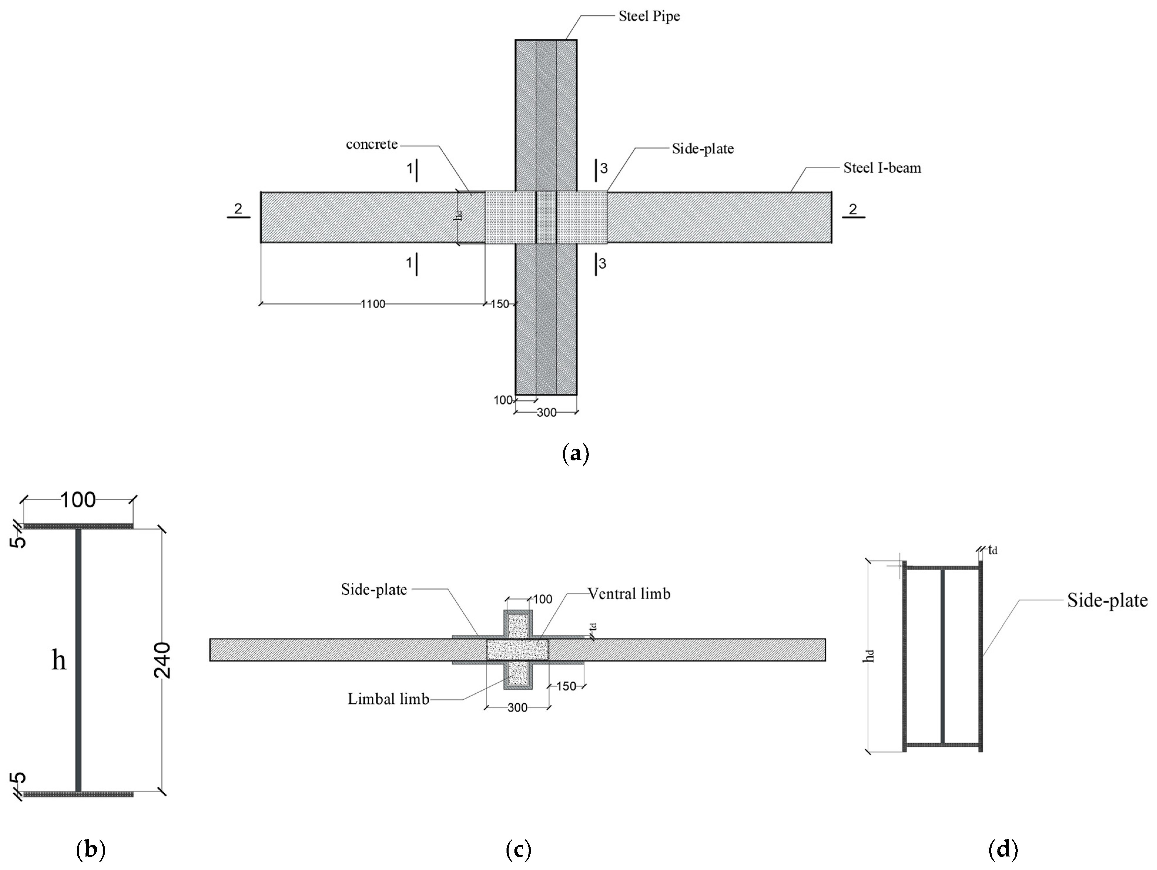
2.1. Joint Detailing

In this study, the joint of the middle column in a plane frame was selected as the research prototype. Nine joint models with or without side plates were designed at a scale ratio of 1:2. The effects of the side plates, axial compression ratio, and side plate height and thickness on the flexural capacity of joints were investigated. Table 1 lists the specimen numbers and parameters. Steel tubular columns, steel beams, and side plates were all made of Q235 steel, and the core concrete was C40 concrete.

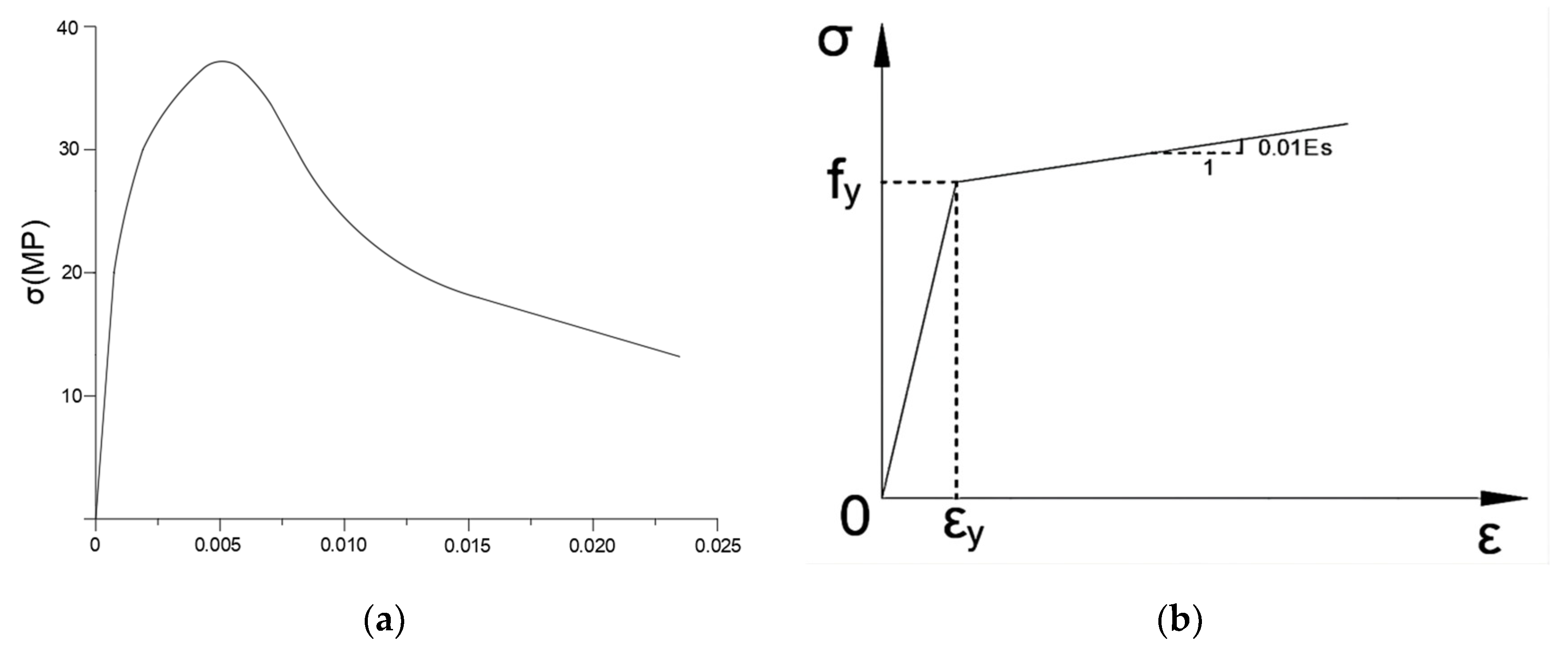
2.2. Material Constitutive Model and Element Selection

The joint model consisted of cross-shaped concrete-filled steel tubular columns, core concrete, side plates, and I-shaped steel beams. ABAQUS software was used to establish the plastic damage model of core concrete by adopting the material constitutive model proposed by Han [30] because it considers the confinement effect of a steel tube on core concrete under axial compression. The stress–strain curve of concrete is shown in Figure 2a. In this model, the expansion angle ψ was 30°, and the flow potential offset value ε was 0.1. The ratio of the biaxial ultimate compressive strength to the uniaxial ultimate compressive strength (ƒb0c0) was 1.16. The ratio of the second stress invariant on the tensile meridian plane to that on the compressive meridian plane K was 0.6667, and the viscous coefficient μ was 0.0005.
A kinematical hardening model and von Mises yield criterion were adopted to establish the FEA model by considering the Bauschinger effect under cyclic loading. Figure 2b shows the linear strengthened elastic–plastic model as a steel constitutive model, where the elastic modulus is 2.06 × 10⁵ MPa, and the Poisson’s ratio is 0.3. In this model, the cross-shaped concrete-filled steel tube columns, core concrete, side plates, and I-shaped steel beams were meshed as three-dimensional (3D) solid elements defined by eight-node reduced integration in ABAQUS. The grids were generated by structured meshing and sweeping to ensure the efficiency and precision of the calculation.

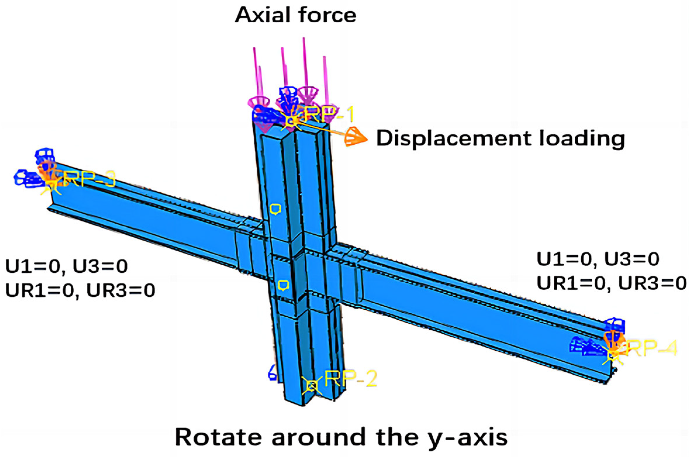
2.3. Contact, Boundary Condition, and Loading

In this study, the steel tube and concrete formed a surface-to-surface contact. For contact analysis, the principle of selecting master and slave surfaces using ABAQUS is that the one with stiffer body as master surface [31]. The elastic modulus of steel is higher than that of concrete. Thus, the steel tube is the primary surface and the concrete is the secondary surface. Tangential and normal behaviors in ABAQUS were set. The tangential behavior was simulated by using the Coulomb friction model [32] with a friction coefficient of 0.6 [33], and the normal behavior was simulated by using the default hard contact model in ABAQUS, i.e., surfaces form a contact when bearing pressure, and they detach when bearing tension [34]. Since the steel tube column is designed to be welded with side plates and steel beams, these parts are merged together by using the ASSEMBLY module to stimulate the contact between these parts in the actual condition. For achieving better convergence of the model, parts are set as independent parts, which are partitioned as a whole and meshed to ensure that they share the same element joints.
This study adopted the column-end loading method in Specification of Testing Methods for Earthquake Resistant Building [35], i.e., a constant axial pressure is applied at the top of the column, and then a reciprocating horizontal load is applied at the reference point with a displacement increment of 5 mm. The loading regime is shown in Figure 3. The loading stops when either the entire section of the model reaches the ultimate stress or its ultimate bearing capacity drops below 85%. The top surface of the column is coupled with reference point RP1, for which the translation in the y direction and the rotation in the y and z directions are restricted. The axial load at the column top is simulated by applying pressure on the top surface of the column, and horizontal earthquake action is simulated by applying reciprocal horizontal displacement to the reference point RP1 in increments of 5 mm. The bottom surface of the column is coupled with reference point RP2, for which the translations in x, y, and z directions are restricted. To avoid instability in the overall structure, the rotations of the column bottom around the x and z axes are also restricted. The surfaces of the left and right beam ends are coupled with RP3 and RP4, respectively; their degree of freedom in the z direction is limited. The loading diagram is shown in Figure 4.

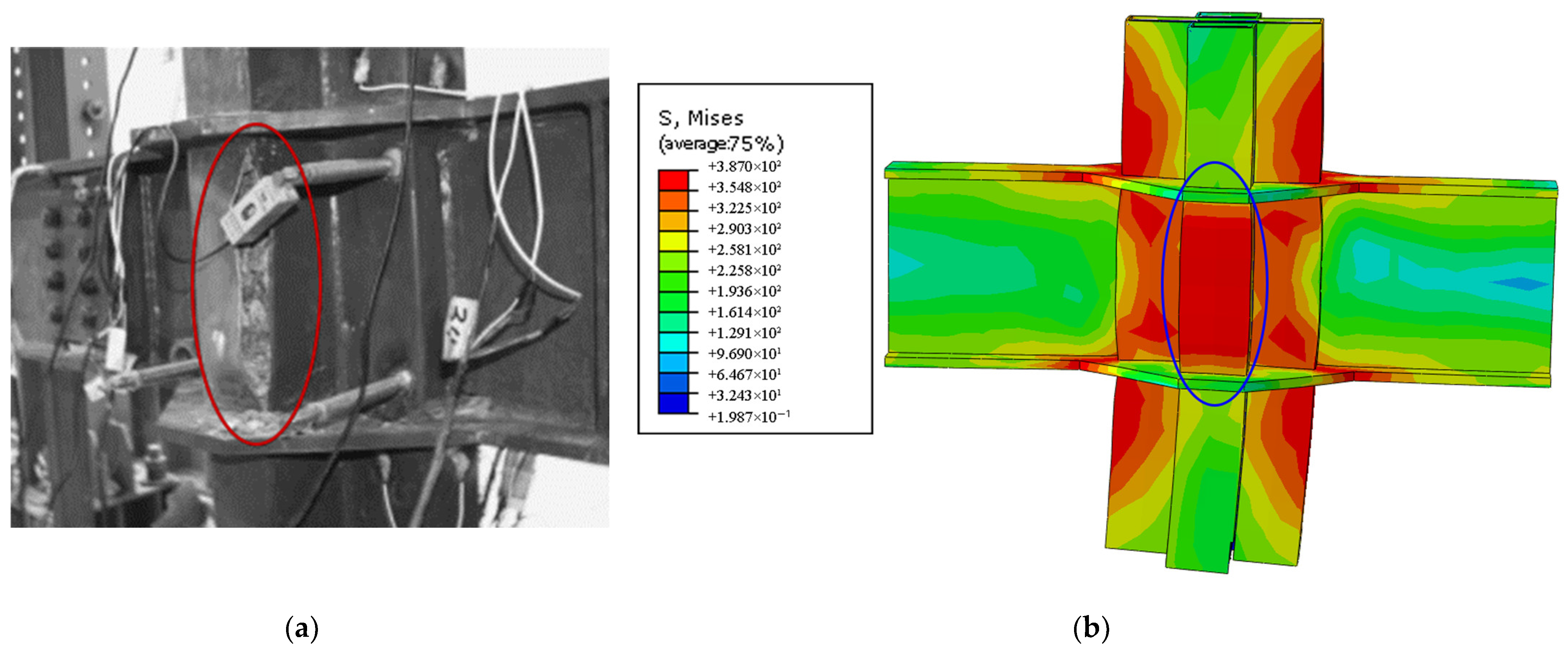
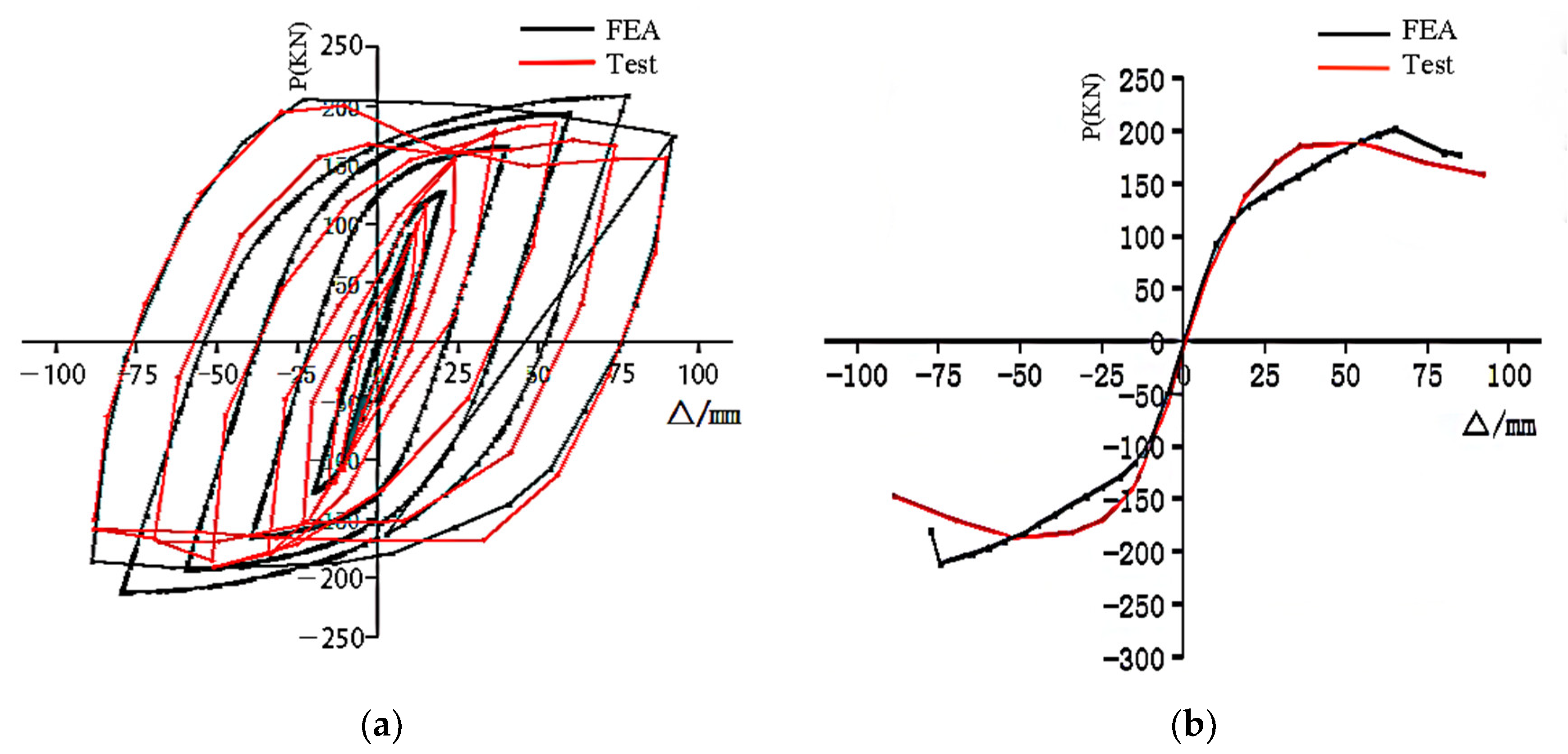
2.4. Calibration of the Finite Element Model

The material constitutive model, interaction between column and beam, and boundary conditions adopted in this study were calibrated by comparing FEA results to the experimental results on the cross-shaped external annular steel plate joint (MJ-2) reported by Xu [14]. The comparison of the failure stages of the actual specimen and the simulated results is shown in Figure 5. The failure of the joint in the test is seen as the cracking of the concrete-filled steel tube column weld in the joint panel zone, and the core concrete showed diagonal cracking. The FEA results show that the steel tube in the joint panel area bulges, and the stress in the core concrete is mainly distributed in the diagonal inclined band area. Figure 6 shows the finite element stimulated and test curves, revealing that the simulation curve is basically consistent with the test curve, and the error between the simulated ultimate bearing capacity and that obtained from the test is small (within 10%). The FEA results are in good agreement with the test results, thereby validating the finite element parameters adopted in this work.

3. Results and Discussion

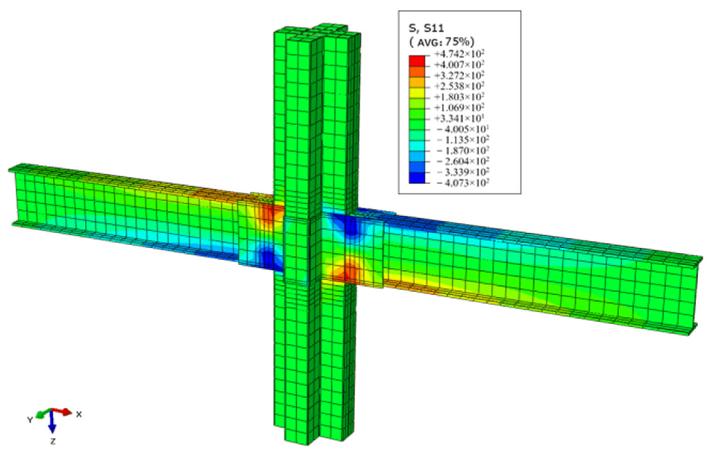
3.1. Mechanical Characteristics and Failure Modes

Specimen JD1 was selected as an example because the failure phenomenon and characteristics of JD3–JD8 were similar to those of JD1. Figure 7 below shows the von Mises stress nephogram acquired by performing the low-cycle reciprocating loading test. Figure 7a shows that connections among the steel tube columns, beam flanges, and side plates begin to yield when the horizontal displacement of column ends increases to 37.44 mm, while the other parts of the core concrete, steel tube column, and steel beam are still in the elastic stage. The plasticity of the joint panel zone develops fully with further increase in displacement. The joint reaches the ultimate state when the horizontal displacement increases to 100.34 mm. At this time, the ultimate bearing capacity is 202.04 kN, as shown in the von Mises stress nephogram in Figure 7b. Subsequently, as loading continues, the bearing capacity starts to decline. Once the bearing capacity reaches 85% of the ultimate bearing capacity, the loading ends.
PEEQ is the result of the accumulation of plastic strains throughout the deformation process. The absolute value of each plastic strain increment is summed and its value will only be positive Figure 8 shows the equivalent plastic strain (PEEQ) in the loading process of specimen JD1, revealing the expansion process of the plastic hinge. First, a plastic zone is formed at the column corner of the beam–column connection. Then, the plastic hinge gradually expands on the column walls and side plates with an increase in loading displacement. Finally, the bearing capacity of joints starts declining because of the joint failure, which is caused by the penetration of the plastic hinge into the entire section of the beam–column connection.
The von Mises stress nephogram of specimen JD2 under low-cycle reciprocating loading is shown in Figure 9. The connection between the upper and lower flanges of the steel beam and the steel tube column reaches the yield strength, and the column base shows obvious stress concentration when the horizontal displacement increases to 36.59 mm. At this time, the other parts of the joints are in the elastic stage. As loading continues, the buckling of the beam–column connection becomes more obvious. The stress at the joints and the beam end near the joints reaches the ultimate stress, with displacement reaching 129.91 mm. At this time, the joint is in the ultimate state, and the ultimate bearing capacity is 143.31 kN.
According to the FEA results, in all joints, failure occurs at the beam–column connections, while the other parts are still in the elastic stage. In the case of joint specimen JD2 without side plates, the column at the height of the upper and lower flanges of the beam at the beam–column connection section yields first, and the plastic hinge penetrates into this section as the displacement increases. The joint with side plates first buckles on the side plates and the column that is at the section of the steel tube column–beam connection, and finally, the plastic hinge penetrates this section. The failure mode of the joint model with and without side plates is regarded as a “column–hinge failure”.

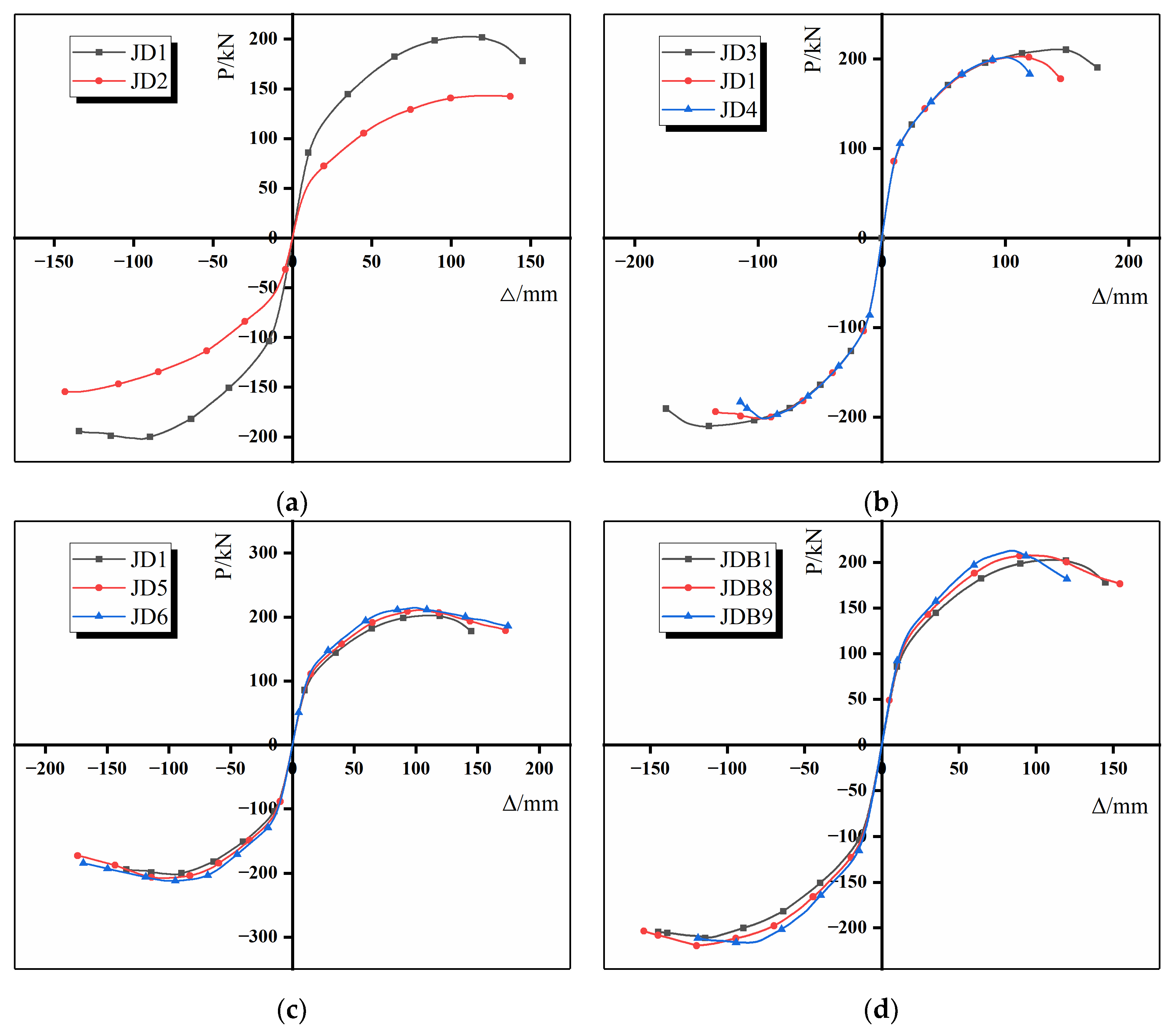
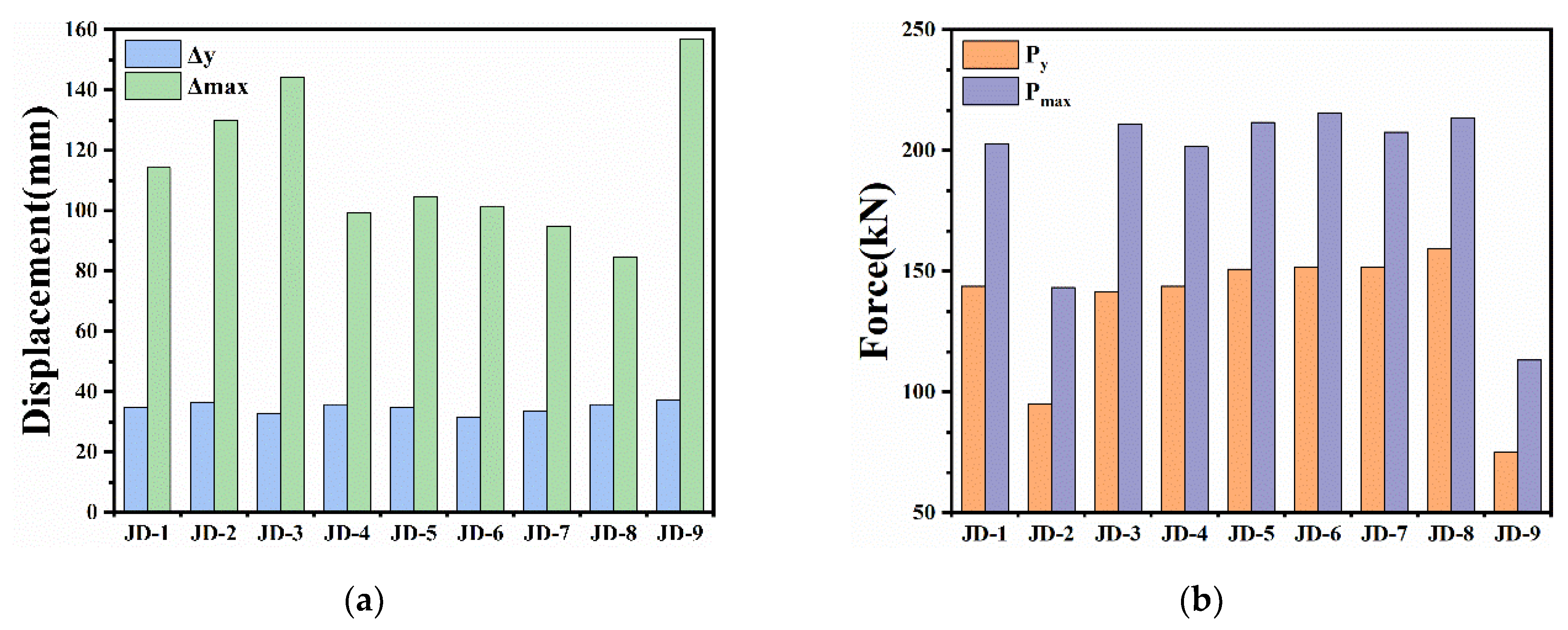
3.2. Parametric Study

To investigate the flexural capacity of the joints with side plates, two types of joints with and without side plates were examined in this study. The effect of the axial compression ratio and the side plate height and thickness on the load-bearing capacity of the joints with side plates was analyzed. Figure 10 shows the effects of each parameter on the joint skeleton curve.
The skeleton curves of specimens JD1 and JD2 are shown in Figure 10a. The figure shows that skeleton curve slope of the specimen with side plates is greater than that of joints without side plates, and the initial stiffness of the joints both increases. Meanwhile, the side plates bear a part of the bending moment of the beam ends, thereby causing a remarkable increase in the ultimate bearing capacity. Therefore, the stress concentration at the connection between the sidewall of the steel tube column and the beam is significantly weakened, and the flexural capacity in the joint panel zone is enhanced.
The skeleton curves of specimens JD1, JD3, and JD4 in Figure 10b show that the skeleton curve of all specimens basically overlapped in the early stage of loading, while the ultimate bearing capacity gradually decreases with an increase in the axial compression ratio. This change is attributed to the fact that the plastic damage to the concrete-filled steel tube column in the joints increases with the axial compression. Insufficient steel beam deformation leads to less energy absorption, thereby gradually reducing the bearing capacity of the joints.
The skeleton curves of specimens JD1, JD5, and JD6 in Figure 10c show that the skeleton curve slope, initial stiffness of joints, and ultimate bearing capacity increase with an increase in the height of the side plates.
Similarly, the skeleton curves of specimens JD1, JD7, and JD8 in Figure 10d show that the skeleton curve slope, initial stiffness of joints, and ultimate bearing capacity increase with an increase in the thickness of the side plates.
To summarize, the joint specimens go through three stages: yield state, ultimate state, and failure state under the reciprocating cyclic loading. The load and displacement of the feature point of each model are given in Table 2 and Figure 11.

3.3. Force Transmission Mechanism and Tensile Strength of Joints

Figure 12 shows the bending moment transmission mechanism of specimen JD1 during the loading test. The figure reveals that the moment can be converted into two pairs of couples (tension and compression), when the beam end is subjected to the bending moment. Among them, one pair of couples act on the upper and lower beam flanges. The tension separates the steel tube column and core concrete, resulting in the buckling of the steel tube column sidewall, and the compression is transferred to core concrete through the steel tube column sidewall. Another pair of couples act on the upper and lower parts of the side plates. Therefore, the tensile strength in the joint panel zone is composed of the tensile bearing capacity of steel tube column flanges and that of the side plates.

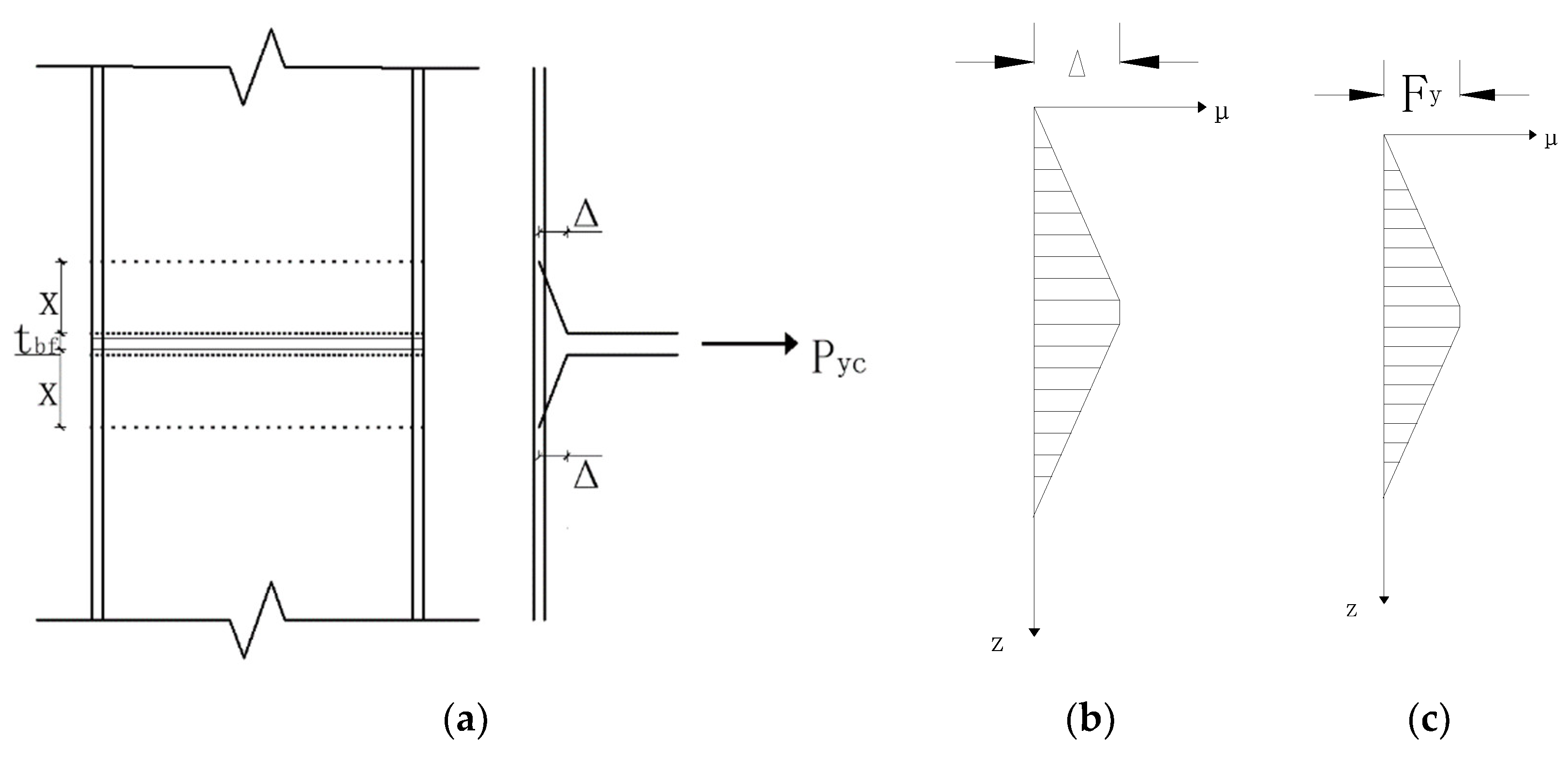
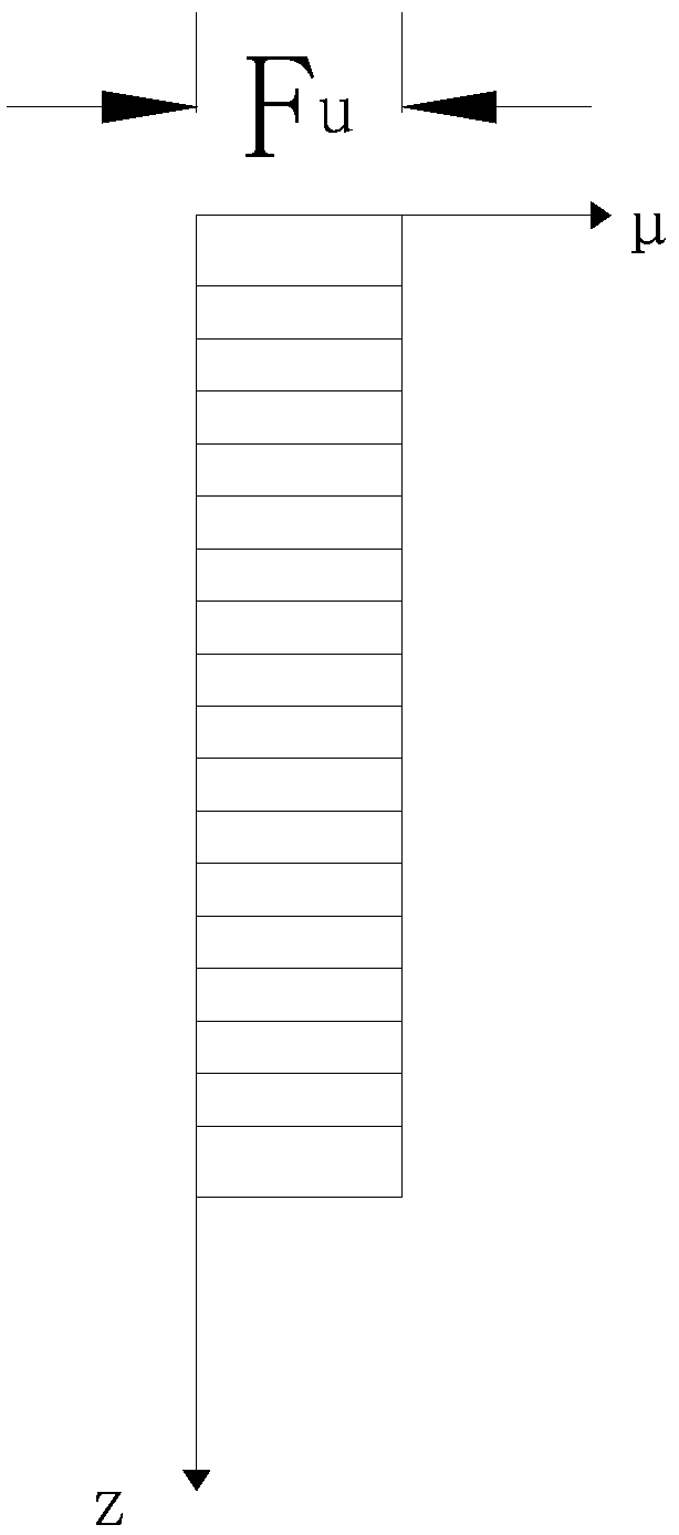
3.3.1. Calculating the Ultimate Tensile Strength of a Square Steel Tube Column Flange by the Yield Line Theory

Previous studies showed that failure occurs on the sidewall of concrete-filled steel tubular columns when the flanges of the beams and columns had identical widths [36,37]. Nie [38] analyzed the yielding tensile strength of the joints by the yield line failure mechanism when the beam–column flanges had equal widths. Assuming that the stress distribution of the tube wall was consistent with the deformation, the joint yielding mechanism, the deformation and stress diagrams were obtained as shown in Figure 13. Based on the principle of virtual work, the formula is as follows:
E c = 4 M p 2 B c Δ x + 4 0 x f y , a c f t b f x z Δ x z d z + 2 f y , a z f t b f 2 Δ = P y c Δ
P y c = 4 M p 2 B c x + 4 3 f y , a c f t b f x + 2 f y , a c f t b f 2
M p 2 = ( 1 n 2 ) f y , c f t c f 2 4
x = 3 M p 2 B c f y , a c f t b f
Figure 7b shows the von Mises stress nephogram of specimen JD1 in the ultimate state. The plasticity of the column sidewall develops sufficiently after yielding. The sidewall at a certain height (x) of the beam flange reached the ultimate stress in the ultimate state. Figure 14 shows the corresponding stress distribution of the sidewall. On replacing fy,acf with fu, we obtain Equations (5) and (6).
E c = 4 M p 2 B c Δ x + 4 0 x f u z Δ x z d z + 2 f u t b f 2 Δ = P u c Δ
P u c = 4 M p 2 B c x + 4 3 f u t b f x 2 + 2 f u t b f 2
where fu is ultimate tensile strength of steel and x can be determined by Puc calculated by the smallest δPycx = 0. Thus, we obtain the following relation:
x = 3 M p 2 B c 2 f u t b f 3
The ultimate tensile capacity of the column flanges can be calculated by applying Equation (7) to Equation (6), where the calculation of Mp2 in Equation (6) is the same as that in Equation (3). However, this formula does not consider the support of core concrete to the column sidewall flanges. The calculation results of specimens JD2 and JD9 show that the core concrete improves the flexural capacity of the joints as the core concrete provides the support for the steel tube flanges, thereby avoiding the premature buckling of the steel tube. The ultimate bearing capacity of specimens JD2 and JD9 are 143.31 and 113.28 kN, respectively, and the ultimate bearing capacity of the joint with core concrete is 26.51%, which is higher than that of the joint without core concrete. Based on these results, we propose α, i.e., the strength coefficient of core concrete. Having considered the support of core concrete to column flanges, the formula of the ultimate tensile capacity of column flanges is given as follows:
P u c = α P u c
where α is 1.26.

3.3.2. Ultimate Tensile Capacity of the Side Plates

In the loading process, a part of the bending moment at the beam ends is transferred from the side plates to the steel tube column in the form of tension and compression. By analyzing the von Mises stress distribution in the ultimate load state, the tension and compression on the side plates are assumed to be distributed uniformly on both sides of the horizontal median line of the side plate, as shown in Figure 8. Based on the static equilibrium method, the simplified formula for the ultimate horizontal tension of the side plates can be expressed as follows:
P u d = 2 f u d ( h d 2 ) t d
where td is the thickness of the side plates, hd is the height of the side plates, and fud is the ultimate strength of the side plates.

3.3.3. Ultimate Flexural Capacity of the Joints

The ultimate tensile capacity of the column flange to the steel beams and to side plates was calculated according to the yield line theory and static equilibrium method. The obtained results were multiplied by their center distance of resistance to obtain their contribution to flexural capacity of joints. The ultimate flexural capacity of the joints is the sum of the two:
M u = P u c ( h b t b ) + P u d h d 2
where hb is the height of the steel beams and tb is the thickness of the steel beam flanges.

3.4. Ultimate Flexural Capacity of the Joints

Table 3 lists the comparison results between the ultimate bending moment values obtained from finite element simulation and the joints flexural bearing capacity calculated by Equation (10), which can verify the ultimate flexural capacity of joints. It reveals that the column flanges in joints with side plates transmit more bending moment, and the side plates transmit a part of the bending moment. The contribution of the side plates to the joints can be improved by enlarging the side plates; the maximum error between the calculated and numerical simulation result values is 15%. The large error may be caused by the penetration of the joints by the plastic hinges between the column flanges and the beams, resulting in a decrease in the bearing capacity, while the side plate does not function sufficiently during the actual loading process. The calculated values obtained from the flexural capacity formula derived in this work are consistent with the FEA results, which provide reference for the design of such joints.

4. Conclusions

This paper presents a theoretical basis for the application of specially shaped concrete-filled steel tubular column structures. Based on the existing joint structure of concrete-filled steel tubular special-shaped column and steel beam, a cruciform concrete-filled steel tubular column steel beam joint with side plate connection is proposed and designed. The force transfer mechanism and failure characteristics of the joint are revealed using FEA, and the following conclusions are drawn.
(1) The FEA shows that the side plates designed in this work can transmit the force between the beam and column and weaken the stress concentration at the connections between the column flanges and the beams, thereby effectively avoiding the premature failure of the beam–column connection.
(2) Parameters of the cross-shaped concrete-filled steel tube column–steel beam joints with side plates were analyzed in this study. The analysis revealed that the ultimate bearing capacity of the model with side plates was increased by 41.5% compared with that without side plates; the ultimate bearing capacity of the joints decreased with an increase in the axial compression ratio. Furthermore, the initial stiffness and the ultimate bearing capacity of the joints increase slightly with an increase of height and thickness of the side plate, and the maximum increase was only 6.2%.
(3) Based on the FEA results, the yield mechanism of the steel tube column web limb flange was established. The strength coefficient of the core concrete was proposed to calculate the ultimate tensile capacity of the tube column flange to the steel beam. According to the static equilibrium method, a simplified formula was derived to calculate the tension transferred by side plates. Using this formula, the flexural capacity formula of the cross-shaped concrete-filled steel tubular column–steel beam joints with side plates was obtained, and the values calculated using this formula were consistent with the FEA results.
(4) The proposed formula for calculating flexural capacity of joint depends on effects of both steel tube column flange and side plates. Calculation analysis shows that the flexural capacity of joint with side plates was improved 60.3% in comparison with that without side plates. Furthermore, the ultimate bearing capacity of joint was increased by 18.8% as increasing thickness of side plates, and which was only 5.6% with the increase of side plates’ height. This shows that side plates’ height has little effect on the flexural capacity of the joint under the condition of design requirements.
In view of the results, it is feasible to design the joint between cross-shaped CFST columns and steel beams with side plate. The new design complies with the seismic design principles of “strong column-weak beam” and “strong joint-weak component”. Further studies will focus on the optimization design of side plate, which may promote the application of frames with CFST columns connected to steel beams in high-level architectures in high-intensity earthquake regions.

Author Contributions

Y.Z. conceived the simulation; Y.Z. and M.Y. designed the simulation; M.Y. performed the simulation; Y.Z., M.Y., F.L. and Q.L. analyzed the data; F.L. and M.Y. wrote the paper. All authors have read and agreed to the published version of the manuscript.

Funding

The paper was funded by the Key Scientific Research Project of Higher Education of Henan Province, China (Grant No.22B560023), the Key scientific research project plan of colleges and universitiesScientific Research Project Plan of Colleges and Universities in Henan Province, China [grant number 20zx009].

Institutional Review Board Statement

Not applicable.

Informed Consent Statement

Not applicable.

Data Availability Statement

Not applicable.

Conflicts of Interest

The authors declare no conflict of interest.

Abbreviations

MuUltimate flexural capacity of joints
PudUltimate horizontal tensile force of the side plates
hbHeight of the steel beams
tbThickness of the steel beam flanges
tdThickness of the side plates
hdHeight of the side plates
edUltimate strength of the side plates
fuUltimate tensile strength of steel
PucUltimate tensile capacity of column flanges
PucUltimate tensile capacity of square steel pipe flange
tbfThickness of tension flange of steel beam
BcWidth of concrete-filled square steel tube column
EcWork done by tension flange of steel beam to square steel tube column
ΔVirtual displacement
fy,aYield strength of welds at the connection between steel pipe flange and web
fy,cfYield strength of steel plate at the connection between steel pipe flange and web
fy,acf= min(fy,a, fy,cf)
tcfThickness of steel pipe column wall

References

  1. Wang, Q.T.; Chang, X. Analysis of concrete-filled steel tubular columns with “T” shaped cross section (CFTTS). Steel Compos. Struct. 2013, 15, 41–55. [Google Scholar] [CrossRef]
  2. Zheng, Y.Q.; Zeng, S.X. Design of L-shaped and T-shaped concrete-filled steel tubular stub columns under axial compression. Eng. Struct. 2020, 207, 110262. [Google Scholar] [CrossRef]
  3. Han, L.-H.; Li, W.; Bjorhovde, R. Developments and advanced applications of concrete-filled steel tubular (CFST) structures: Members. J. Constr. Steel Res. 2014, 100, 211–228. [Google Scholar] [CrossRef]
  4. Han, L.H.; Wang, W.D.; Tao, Z. Performance of circular CFST column to steel beam frames under lateral cyclic loading. J. Constr. Steel Res. 2011, 67, 876–890. [Google Scholar] [CrossRef]
  5. Shariati, M.; Grayeli, M.; Shariati, A.; Naghipour, M. Performance of composite frame consisting of steel beams and concrete filled tubes under fire loading. Steel Compos. Struct. 2020, 36, 587–602. [Google Scholar] [CrossRef]
  6. Alatshan, F.; Osman, S.A.; Hamid, R.; Mashiri, F. Stiffened concrete-filled steel tubes: A systematic review. Thin-Walled Struct. 2020, 148, 106590. [Google Scholar] [CrossRef]
  7. Chen, Z.; Chen, X.; Qunying, Y.E.; Luo, C. Structural Design of Guangzhou New China Mansion. J. Build. Struct. 2000, 3, 2–9. [Google Scholar]
  8. Xing, C.; Chen, Z.; Luo, C. Structural Design of the Guangzhou Minghui Commercial Building. Build. Struct. 2006, 36, 29–32. [Google Scholar]
  9. Liu, X.; Xu, C.; Liu, J.; Yang, Y. Research on special-shaped concrete-filled steel tubular columns under axial compression. J. Constr. Steel Res. 2018, 147, 203–223. [Google Scholar] [CrossRef]
  10. Zhou, T.; Chen, Z.; Liu, H. Seismic behavior of special shaped column composed of concrete filled steel tubes. J. Constr. Steel Res. 2012, 75, 131–141. [Google Scholar] [CrossRef]
  11. Wang, Y.Y.; Yang, Y.L.; Zhang, S.M.; Liu, J.P. Seismic behaviors of concrete-filled T-shaped steel tube columns. Key Eng. Mater. 2009, 400–402, 677–683. [Google Scholar] [CrossRef]
  12. Miller, D.K. Lessons learned from the Northridge earthquake. Eng. Struct. 1998, 20, 249–260. [Google Scholar] [CrossRef]
  13. Xu, C.X.; Wu, Z.J.; Zeng, L. Experimental research on seismic behaviors of T-shaped concrete-filled steel tubular frame joints. In Proceedings of the 4th International Conference on Technology of Architecture and Structure (ICTAS 2011), Xi’an University Architecture & Technol, Xi’an, China, 22–24 September 2011; pp. 38–41. [Google Scholar]
  14. Chengxiang, X.; Bo, W.; Jicheng, Z.; Jinjun, M. Experimental research on seismic behavior of interior joints in the composite frame consisting of CFST crisscross section columns and steel beams. Build. Struct. 2012, 42, 80–83. [Google Scholar] [CrossRef]
  15. Li, Y.T.; Xu, C.X.; Du, G.F. Seismic performance of T-shaped CFT column to steel frame beam connection-experimental study. In Proceedings of the 4th International Conference on Structures and Building Materials (ICSBM), Guangzhou, China, 15–16 March 2014; p. 951. [Google Scholar]
  16. Xue, J.Y.; Li, H.C.; Chen, X.; Lu, X.; Tu, G.X.; Zhong, R.B. Experimental research on seismic damage of T-shaped CFST column to steel beam joints. Structures 2022, 38, 1380–1396. [Google Scholar] [CrossRef]
  17. Li, H.C.; Xue, J.Y.; Chen, X.; Tu, G.X.; Lu, X.; Zhong, R.B. Experimental research on seismic damage of cross-shaped CFST column to steel beam joints. Eng. Struct. 2022, 256, 113901. [Google Scholar] [CrossRef]
  18. Kim, C.H.; Lee, E.T. Cyclic Behavior of Beam-to-Concrete Filled Steel Tube Column Connections. Int. J. Steel Struct. 2005, 5, 399–406. [Google Scholar]
  19. Xiong, Q.Q.; Zhang, W.; Chen, Z.H.; Du, Y.S.; Zhou, T. Experimental Study of the Shear Capacity of Steel Beam-to-L-CFST Column Connections. Int. J. Steel Struct. 2019, 19, 704–718. [Google Scholar] [CrossRef]
  20. Xiong, Q.Q.; Wu, W.B.; Zhang, W.; Chen, Z.H.; Liu, H.B.; Su, T.C. Study on the progressive collapse resistance of CP-FBSP connections in L-CFST frame structure. Steel Compos. Struct. 2022, 44, 423–436. [Google Scholar] [CrossRef]
  21. Zhang, W.; Jia, S.Y.; Xiong, Q.Q.; Chen, Z.H.; Liu, H.B.; Su, T.C.; Du, Q.Z. Investigation of side plate connections in an S-CFST column frame under a column-loss scenario. Structures 2021, 32, 1302–1319. [Google Scholar] [CrossRef]
  22. Zhang, W.; Chen, Z.H.; Xiong, Q.Q.; Zhou, T.; Rong, X.; Du, Y.S. Experimental seismic behaviour of L-CFST column to H-beam connections. Steel Compos. Struct. 2018, 26, 793–808. [Google Scholar] [CrossRef]
  23. Huang, Y.Q.; Hao, J.P.; Bai, R.; Fan, C.L.; Xue, Q. Mechanical Behaviors of Side-Plate Joint Between Walled Concrete-Filled Steel Tubular Column and H-Shaped Steel Beam. Adv. Steel Constr. 2020, 16, 346–353. [Google Scholar] [CrossRef]
  24. Liu, J.C.; Yang, Y.L.; Liu, J.P.; Zhou, X.H. Experimental investigation of special-shaped concrete-filled steel tubular column to steel beam connections under cyclic loading. Eng. Struct. 2017, 151, 68–84. [Google Scholar] [CrossRef]
  25. Cheng, Y.; Yang, Y.L.; Li, B.Y.; Liu, J.P.; Chen, Y.F. Mechanical behavior of T-shaped CFST column to steel beam joint. J. Constr. Steel Res. 2021, 187, 106774. [Google Scholar] [CrossRef]
  26. Cheng, Y.; Yang, Y.L.; Li, B.Y.; Liu, J.P. Research on seismic behavior of special-shaped CFST column to H-section steel beam joint. Adv. Struct. Eng. 2021, 24, 2870–2884. [Google Scholar] [CrossRef]
  27. Cheng, Y.; Yang, Y.L.; Li, B.Y.; Liu, J.P.; Yan, W.X.; Chen, Y.F. Shear resistance of multi-cell special-shaped CFST column to H-section steel beam joint. Structures 2022, 41, 419–433. [Google Scholar] [CrossRef]
  28. Liu, X.C.; Wu, X.T.; Chen, X.S. Seismic performance of joint between L-shaped CFST column and H-section beam with lower plate and extended flange plate. Eng. Struct. 2022, 261, 114283. [Google Scholar] [CrossRef]
  29. Li, B.Y.; Yang, Y.L.; Liu, J.P.; Liu, X.G.; Cheng, Y.; Chen, Y.F. Behavior of T-shaped CFST column to steel beam connection with U-shaped diaphragm. J. Build. Eng. 2021, 43, 102518. [Google Scholar] [CrossRef]
  30. Han, L.H. Concrete-Filled Steel Tubular Structures-Theory and Practice, 3rd ed.; Science Press: Beijing, China, 2016. [Google Scholar]
  31. Dassault Systèmes Simulia. ABAQUS Analysis User’s Manual (Version 6.14); Dassault Systèmes Simulia: Providence, RI, USA, 2016. [Google Scholar]
  32. Zhou, Q. Design and Construction Manual for Steel and Concrete Structures; China Architecture & Building Press: Beijing, China, 1991. [Google Scholar]
  33. Tong, M. Study on Seismic Performance of Concrete-Filled Steel Tube (CFST) Column-Beam Joints with Double Side Plates. Ph.D. Thesis, Wuhan University, Wuhan, China, 2013. [Google Scholar]
  34. Chen, Q. Research on Seismic Performance and Load-Carrying Capacity of Joints between Concrete-Filled Square Steel Tubular Special-Shaped Columns and Steel Beams; China Architecture & Building Press: Beijing, China, 2014. [Google Scholar]
  35. JGJ101-2015; Specification of Testing Methods for Earthquake Resistant Building. China Architecture & Building Press: Beijing, China, 2015.
  36. Lu, L.H. The Static Strength of I-Beam to Rectangular Hollow Section Column Connections. Ph.D. Thesis, Universiteit Delft, Delft, The Netherlands, 1997. [Google Scholar]
  37. Liu, J.X. Study on Earthquake Resistant Behavior of Reinforced Concrete Beam to T-Shaped Concrete-Filled Rectangular Composite Tubular Column Exterior Joint. Ph.D. Thesis, Wuhan University of Technology, Wuhan, China, 2015. [Google Scholar]
  38. Nie, J.G.; Qin, K.; Zhang, G.B. Experimental research and theoretical analysis on flexural capacity of connections for concrete-filled steel square tubular columns with inner diaphragms. J. Archit. Civ. Eng. 2005, 22, 42–49+54. [Google Scholar]
Figure 1. Joint profile ( h d : side panel height; t d : side plate thickness; Unit: mm). (a) Elevation; (b) 1-1 profile; (c) 2-2 profile; (d) 3-3 profile.
Sustainability 15 00541 g001
Figure 2. Material constitutive model. (a) Stress–strain constitutive curve of concrete; (b) Bilinear constitutive model of steel (fy: yield strength; Es: elastic modulus of steel; εy: yield strain).
Sustainability 15 00541 g002
Figure 3. Loading diagram (U1: translational degree of freedom in x direction; U3: translational degrees of freedom in z direction; UR1: rotation degree of freedom in x direction; UR3: rotation degree of freedom in z direction).
Sustainability 15 00541 g003
Figure 4. Loading mechanism (Δy: displacement of joint yielding).
Sustainability 15 00541 g004
Figure 5. Comparison of failure of the tested specimen and simulated failure. (a) Failure damage of the specimen; (b) Failure damage simulated by the FEA.
Sustainability 15 00541 g005
Figure 6. Comparison of the tested and simulated results. (a) Hysteretic curve; (b) Skeleton curve.
Sustainability 15 00541 g006
Figure 7. JD1: von Mises stress cloud map. (a) Yield state; (b) Ultimate state.
Sustainability 15 00541 g007
Figure 8. JD1: model plastic hinge development flowchart.
Sustainability 15 00541 g008
Figure 9. JD2: von Mises stress cloud map. (a) Yield state; (b) Ultimate state.
Sustainability 15 00541 g009
Figure 10. Influence of the main parameters on the node skeleton curve. (a) Specimen with or without side plates; (b) Axial compression ratio; (c) Side plate height; (d) Side plate thickness.
Sustainability 15 00541 g010
Figure 11. Load and displacement of the feature point of each model. (a) Yield displacement and ultimate displacement; (b) Yield load and ultimate load.
Sustainability 15 00541 g011
Figure 12. JD1: force transmission mechanism of the bending moment.
Sustainability 15 00541 g012
Figure 13. Calculation model of joint tensile bearing capacity with beam and column flanges of equal widths. (a) Joint yield line distribution of a joint; (b) Deformation distribution of the tube wall; (c) Stress distribution of the tube wall [38].
Sustainability 15 00541 g013
Figure 14. Stress distribution of the tube wall in the limit state.
Sustainability 15 00541 g014
Table 1. Table of the geometric dimensions and parameters of the node model (mm).
NumberPlate/No Side PlateAxial Compression RatioSide Plate HeightSide Plate ThicknessFactor
JD 1side plate0.32664Benchmark model
JD 2no side plate0.3 side plate/No side plate
JD 3side plate0.22664axial compression ratio
JD 4side plate0.42664
JD 5side plate0.32864Side plate height
JD 6side plate0.33064
JD 7side plate0.32665Side plate thickness
JD 8side plate0.32666
JD 9side plate0.32664Not filled with concrete
Table 2. Load and displacement at each characteristic point of the model.
Pattern NumberYield StateLimit State
Py (kN)Δy (mm)Pmax (kN)Δmax (mm)
JD-1143.8934.66202.83114.3
JD-295.1936.59143.31129.9
JD-3141.6232.65210.94144.16
JD-4143.8935.84201.7299.34
JD-5150.9634.66211.73104.57
JD-6151.8131.65215.46101.2
JD-7151.8133.65207.694.95
JD-8159.5935.84213.3884.51
JD-975.1337.21113.28157.03
Table 3. Comparison of theoretical calculation results and FEA results of the ultimate flexural capacity of joints (kN·m).
Joint NumberMusMudMuMuMu/Mu
JD186.7952.36139.15136.911.02
JD286.79 86.7996.730.90
JD389.1352.36141.49142.380.99
JD483.4452.36135.8136.161.00
JD586.7956.30143.06142.921.00
JD686.7960.23147.02145.921.01
JD786.7965.45152.24140.131.09
JD886.7978.54165.33144.031.15
JD968.88 68.8876.460.90
Mean value 1.02
Standard deviation 0.07
Note: Mus is the ultimate flexural capacity provided by the column flange; Mud is the contribution of the side plates to the ultimate flexural capacity of the joints; Mu is the ultimate flexural capacity of the joints. All the values were calculated according to the formula derived in this work. Mu is the ultimate flexural capacity of the node calculated according to the FEA results.
Disclaimer/Publisher’s Note: The statements, opinions and data contained in all publications are solely those of the individual author(s) and contributor(s) and not of MDPI and/or the editor(s). MDPI and/or the editor(s) disclaim responsibility for any injury to people or property resulting from any ideas, methods, instructions or products referred to in the content.

