Article

Numerical Analysis of Groundwater Effects on the Stability of an Abandoned Shallow Underground Coal Mine

by
Ioannis E. Zevgolis
1,*,
Alexandros I. Theocharis
2,
Alexandros V. Deliveris
2 and
Nikolaos C. Koukouzas
2
1
School of Mining and Metallurgical Engineering, National Technical University of Athens, 15773 Athens, Greece
2
Chemical Process & Energy Resources Institute, Centre for Research & Technology Hellas, 15125 Athens, Greece
*
Author to whom correspondence should be addressed.
Sustainability 2023, 15(1), 529; https://doi.org/10.3390/su15010529
Submission received: 28 November 2022 / Revised: 23 December 2022 / Accepted: 26 December 2022 / Published: 28 December 2022

Abstract

:
This work systematically quantifies groundwater’s effect on the roof stability of underground openings in shallow coal mines and indirectly assesses the potential for sinkhole formation. A specific stratigraphy was analyzed where the opening instability can lead to sinkhole formation, given the geological conditions, the overburden stratigraphy, and the depth of the openings. The groundwater recharge was investigated as an individual rainfall infiltration (short-term) and as groundwater dynamics (long-term), representing the accumulation of infiltrated rainwater with time. In the latter case, two approaches were employed for the porewater pressure calculation: (a) phreatic line with hydrostatic conditions and (b) steady-state flow based on constant groundwater head on the vertical boundaries at the model’s edges. The safety analysis was based on a simplified statics model relating the stability to the bending of the roof, and numerical analysis was employed for the stress analysis. The short-term safety remained unaffected as rainfall water accumulated on the aquitard to form perched water. The long-term safety deteriorated due to the increase of the tensile stresses in the roof of the underground openings with the rise of the groundwater table. The phreatic line approach is the most conservative, resulting in lower safety than steady-state flow.

1. Introduction

Sinkhole subsidence is a time-dependent ground surface deformation process provoked by the rearrangement of the overburden soil cover over shallow underground voids [1,2,3]. When these shallow underground openings collapse, the crumbled overburden material caves into the openings, forming a sub-vertical depression on the ground surface. The formation of sinkholes is divided into two categories: (a) those caused by natural processes, e.g., the chemical dissolution of carbon rocks surrounding existent karst underground cavities [4,5], and (b) those caused by human activities that develop underground space for civil infrastructure—sewages, pipelines, tunnels—or mining operations—coal extraction, quarrying, and mine waste disposals [1,6]. Shallow underground coal mines have recurrently posed problems with subsidence and sinkhole formations [7,8].
Ground settlements induced by shallow underground coal mine operations can be divided into two categories: active subsidence and residual subsidence [3]. Active refers to settlements that develop concurrently with mining operations; residual refers to settlements that evolve after mining operations have ceased and were examined in this work. Residual subsidence has received remarkable attention due to rising public concern and towards the post-coal era [3]. However, the available tools and methodologies for analyzing the roof stability and sinkhole occurrence are often constrained to solutions that mostly rely on empirical and analytical procedures [9,10,11,12,13,14].
Numerical analysis has also been employed for this problem, as it can consider complicated stratigraphy, composite mining configurations, groundwater, seismic excitations, and the stress-strain response of the involved materials [2,15,16,17,18,19,20,21]. These numerical works have been primarily based on approaches that implicitly interpret the behavior of the developed models to qualitatively assess the stability [16,20,21]. In other words, the existing methodologies do not clearly quantify the underground safety and the surface depression. Additionally, the effect of the long-lasting groundwater recharge due to accumulated seasonal rainfall events and the effect of isolated rainfall incidents have not been systematically considered. The effect of groundwater and rainfall have mainly been addressed by the statistical observation and correlations between heavy rainy periods and sinkhole subsidence occurrences without considering the underlying mechanisms of stability [22,23].
In shallow underground coal mining, the primary mechanism related to the opening’s collapse is “roof failure” [1,2,4]; the “roof” denotes the ground layer in direct contact with and just above the excavated openings. If this layer is overlain by soil layers unable to sustain the overburden load, the roof layer collapse can subsequently lead to sinkhole formation. The roof collapse can depend on various factors such as the underground excavation’s height, the mine’s depth, material bulking, and the lateral spreading of the debris [7,8,22]. Overall, the roof’s instability is the initiating and most important factor in sinkhole formation. Two specific main factors contribute to the destabilization of the roof and the formation of sinkholes in abandoned mines: (a) groundwater recharge and (b) long-term deterioration of the rock materials; the effects of the first one, (a), are quantitatively investigated in this work.
The present work proposes a systematic way to quantify the effect of groundwater on the roof stability of underground openings excavated based on the room-and-pillar mining method. That way, it directly considers the primary mechanism mentioned above in the stability analysis. Additionally, it indirectly assesses the potential for sinkhole formation in shallow mining. The stability of the roof is herein based on a simplified statics model typically used in similar cases, relating the stability to the bending and tensile strengths of the roof. In contrast to empirical correlations, the groundwater effect is considered by directly calculating the porewater pressures and their effect on the effective stress distribution and roof stability. Two approaches were employed to quantify the groundwater effect: individual rainfall in the short- term and groundwater recharge in the long term. In that way, both short- and long-term effects can be quantified in a unified way. For the groundwater recharge, the porewater pressure calculation was based on two approaches: (a) a phreatic line with hydrostatic conditions and (b) steady-state flow conditions based on free-field groundwater boundary conditions. The finite element method (FEM) was employed to obtain the stress distribution in all cases. A specific stratigraphy was analyzed where the roof instability can potentially lead to the formation of a sinkhole, given the geological conditions, the overburden stratigraphy, and the depth of the openings.

2. Materials and Methods

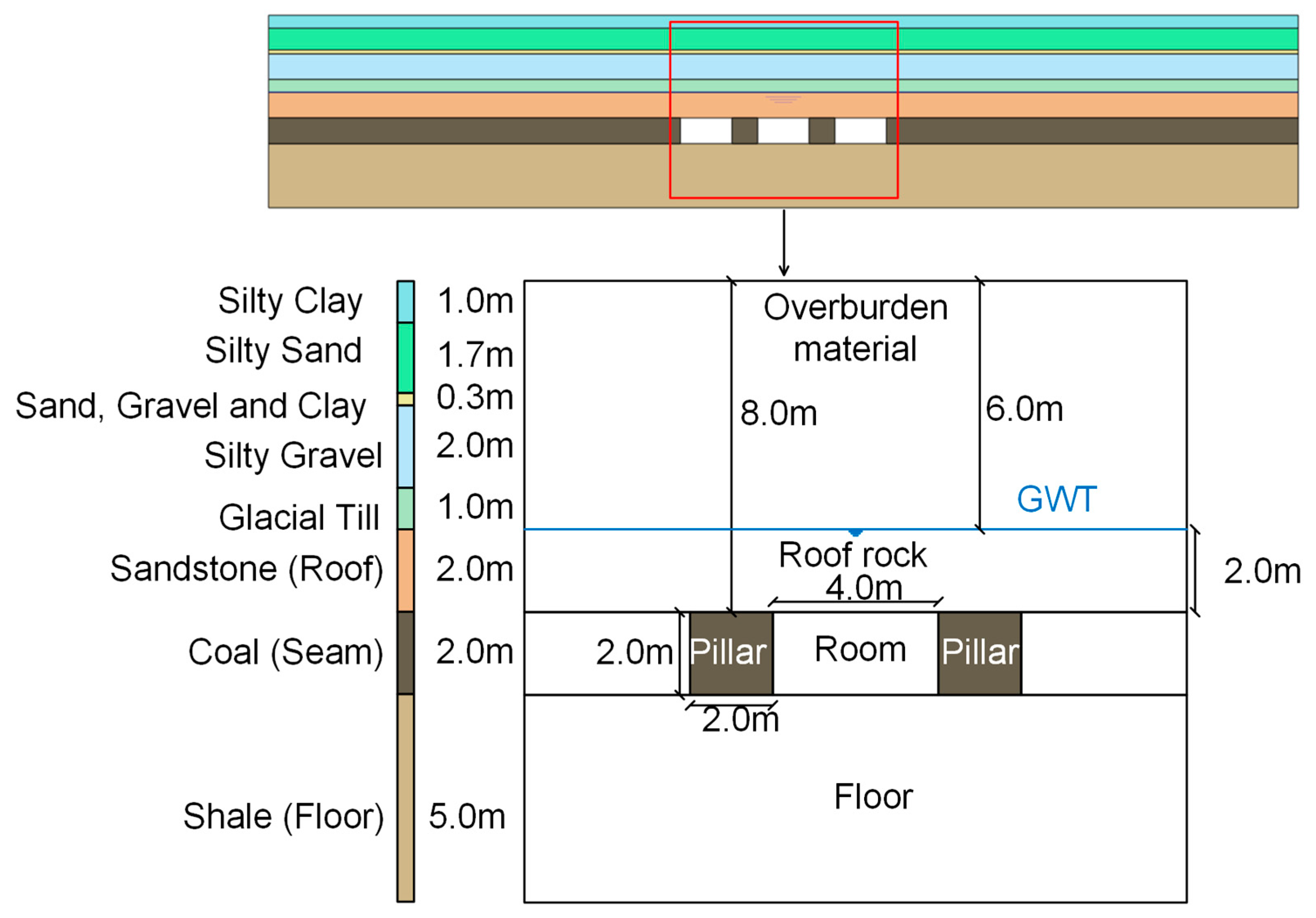
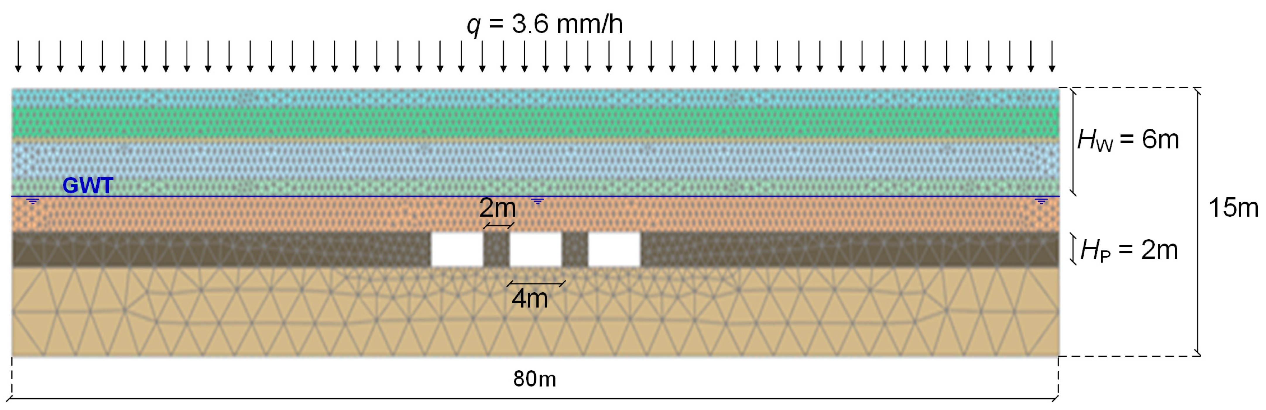
2.1. Stratigraphy and Soil Properties

In this study, a well-documented shallow underground mine was employed to obtain the site stratigraphy, material properties, hydrogeological conditions, geomechanical characteristics, and geometrical characteristics for the following analysis. Salmi et al. [20] presented a typical abandoned shallow underground room-and-pillar coal mine in Dolphingstone, UK. In this work, the stability of the openings was examined, incorporating and analyzing the impact of groundwater. Figure 1 illustrates the stratigraphy of the study site and the geometry of the underground openings. The abandoned shallow underground coal mine is located 8 m beneath the ground’s surface and was operated by the room-and-pillar mining method. The dimensions of the pillars are 2 m × 2 m (width × height), and the room’s dimensions are 2 m × 4 m. The immediate (adjacent) roof layer above the coal seam consists of a competent sandstone bed overlain by consecutive soil layers up to the ground surface. The thickness of the sandstone stratum is 2 m.
Underneath the coal seam, a shale bedrock formation presents high strength and stiffness, so typical bearing capacity failure modes associated with the punching of pillars into the underlying soft strata are not encountered and expected. Given the adequate strength of the coal pillar constituent material and the competent shale base under the coal pillar, the stability of the underground mine is herein related to the deterioration and failure of the immediate sandstone roof, affected by the groundwater and porewater pressures changes in the long-term, after the cease of the mining operations.
Table 1 summarizes the geotechnical parameters of the soil and rock materials, based on data from [20] and on engineering judgment. The moist (γ) and saturated (γsat) unit weight, Young’s modulus (E) and Poisson ratio (ν), the effective soil shear strength parameters: friction angle (φ’) and cohesion (c’), the dilation angle (ψ), and the permeability coefficient (ks) are included for all layers. The tensile strength (σt) is additionally provided for rock materials. The initial groundwater table was 2 m above the coal seam and 6 m below the ground surface. The coal and shale layers were considered non-porous for the analysis; thus, porewater pressures were not calculated in these layers. The groundwater table was within the water-bearing sandstone stratum.
The underground rooms were considered dry, assuming that the mine’s pumping system was still operable or had just been stopped after the cessation of exploitation and the groundwater had not yet started to fill the openings. This assumption was conservative, removing it from the following analysis of the positive impact of groundwater inside the opening [2,6,23], as the flooded water pressure applied at the boundaries of the openings provided notable confinement and enhanced the overall stability of the underground voids (providing that other detrimental processes, such as creep strains or chemical rock degradation, were insignificant). Additionally, groundwater inrush into the openings was likely to occur after the collapse of the immediate roof in surrounding geological settings, such as those encountered in underground coal mines [13].
Unsaturated soil mechanics principles [24,25,26,27] are necessary to evaluate groundwater’s effect accurately, especially during rainfall. These principles govern the hydraulic and, in part, the mechanical response of the unsaturated soil above the phreatic line during rainfall infiltration. The resulting parameters need advanced experimental or equivalent advanced numerical works to be quantified [28,29,30,31] but can also be evaluated based on typical ranges for soil and rock materials. In this work, they were assessed based on the description of the soil and rock layers and typical literature ranges [32,33,34,35]. Table 2 presents the parameters of the unsaturated soil and rock materials of the stratigraphy based on the van Genuchten-Mualem model [36,37]. More details on this model are presented in the next section. The two bottom layers, coal and shale, are considered non-porous.

2.2. Numerical Methodology

The finite element method (FEM) was employed in this work. The stratigraphy of the site, as well as the configuration of the underground openings, were implemented and discretized in finite elements (see Figure 2) using the Plaxis 2D commercial software of Bentley [38]. An assemblage of 6600 triangular, 15-noded elements and 53,303 nodes was employed, with an average element size of 0.6 m.
The bottom boundary was fully fixed, and the vertical boundaries (right and left) had fixed displacements in the horizontal directions. The vertical boundaries were considered open for seepage when a phreatic groundwater table was employed. The initial geostatic stresses were calculated using a fixed, average at-rest earth pressure coefficient ko for all layers (ko equals horizontal over vertical effective stress). Based on the simplified form of Jaky’s equation ko = 1 − sinφ [39], with φ the friction angle, and the stratigraphy of Figure 1 and properties of Table 1, an average friction angle of around 30° results in an average ko = 0.5 for all layers. A staged-construction approach was then followed to simulate the underground voids as the material within the voids was removed to represent the opening of the rooms in discrete calculation stages. Each stage corresponds to the excavation of a single opening followed by the equilibrium of the stresses based on an elasto-plastic drained calculation. The final formation of the underground openings’ configuration was obtained after three consecutive calculation stages. The outer boundaries were set at an adequate distance from the openings so that the numerical results were not affected. The simple elastic-perfectly plastic Mohr-Coulomb constitutive model was used for all materials [40]. The yield surface defining the limit to plasticity is identical to the failure surface defined by φ’, c’, and the dilatancy angle ψ is the crucial parameter for the plastic potential functions and plastic deformations herein defined by a non-associative flow rule. Both shear and tensile strength were considered for the roof, pillar, and floor rock materials.
A 2D plane-strain model was used for the finite element analysis. The room-and-pillar mine configuration is supposed to require a 3D model to fully account for the effect of the transverse excavations (the out-of-plane dimension in 2D models) to be effectively captured. Nevertheless, the 2D conditions have been used for the stability analysis as a simplified version of the 3D problem while keeping in mind the limitations of the 2D simplification [41,42,43]. As this work emphasized the trends in stability following changes in groundwater, these effects were expected to be little affected by the 2D simplification. Nevertheless, the derived outcomes regarding safety factors (SFs) were expected to be non-conservative since the omitted transverse excavations generally apply extra loading to the room-and-pillar system.
Two approaches were used for the groundwater changes and effects on the stability of the underground openings. At first, a short-term approach was adopted, representing the influence of an individual rainfall; a fully coupled hydro-mechanical (flow-deformation) infiltration analysis was performed, directly reproducing a rainfall event with a constant rainfall intensity of 3.6 mm/h that lasts for two days (48 h). The ratio of this rainfall intensity (q) over the saturated permeability of the upper soil layer (ks) (ks = 5 ∙ 10−6 cm/s) was equal to 20, implying a great amount of ponding and surface runoff water; merely a small percentage of the total rainfall height would infiltrate into the soil, and so, the remaining part would remain outside the upper soil layer boundary, acting as a ponding water external surcharge. In the case of greater rainfall intensity, greater amounts of surface runoff water were anticipated, which were not expected to affect the infiltration process crucially, e.g., see [44]. The two days rainfall duration is a noticeable time; in principle, low and moderate-intensity rainfall incidents are often long-lasting [45]. The rainfall event was modeled by imposing an external constant flux boundary condition (q) on the model’s upper horizontal boundary simulating the ground surface. This modeling approach aimed to investigate whether the stability of the underground space was affected by a noticeable individual rainfall incident.
The modeling of rainfall infiltration requires the consideration of the soil suction that develops above the groundwater table in the so-called unsaturated zone. This information can be directly captured by the Soil-Water Characteristic Curve (SWCC), which relates the soil suction with the moisture content of the unsaturated soil. Furthermore, an extra relationship is necessary to determine the unsaturated soil permeability at different saturation [46]. In this work, the hydro-mechanical behavior of unsaturated soil materials was defined via a certain form of the well-known van Genuchten-Mualem model [36,37]. By using this model, the soil’s saturation (Sw) above the groundwater table, in the unsaturated zone, is expressed as a function of the negative porewater pressure uw (soil suction) as:
S w = S r + ( S s S r ) [ 1 + ( g a | u w | g w ) g n ] 1 g n g n
where Sr indicates the soil’s residual saturation, Ss is the soil’s saturation at the fully saturated state, ga is a fitting parameter of the SWCC related to the air entry value of the soil, gn is a fitting parameter of the SWCC governing mainly its slope, and γw is the unit weight of water equal to 9.81 kN/m3. Moreover, the unsaturated soil permeability coefficient (kw), a key soil parameter in the analysis of the rainfall infiltration, is evaluated according to the relative permeability coefficient function:
k w = k s S e g l [ 1 ( 1 S e g n g n 1 ) g n 1 g n ] 2
where gl is a fitting parameter typically equal to 0.5 [36], regardless of the soil type, and Se is the effective saturation of the soil, expressing the normalized moisture content of the unsaturated soil at a given value of soil suction:
S e = S w S r S s S r
The unsaturated soil permeability coefficient (kw) increases with the increase of saturation degree (Sw) and the decrease of soil suction, obtaining its maximum value (equal to the saturated permeability coefficient (ks)) when the soil is fully saturated (Sw = Ss = Se = 1).
The second modeling approach related to long-term changes and investigated the effect of long-term groundwater recharge. This groundwater evolution was simulated by an elevation of the groundwater table inside the soil layer; the higher the groundwater table, the more conservative the results. Two approaches were considered for the porewater pressure calculation: a phreatic line with hydrostatic conditions and a steady state flow with constant groundwater head at the vertical boundaries at the model’s edges. In both variations, the groundwater table (GWT) was elevated from 6 m beneath the ground surface (initial state) to 2 m (final state). Finally, the unsaturated zone was again simulated as described above.

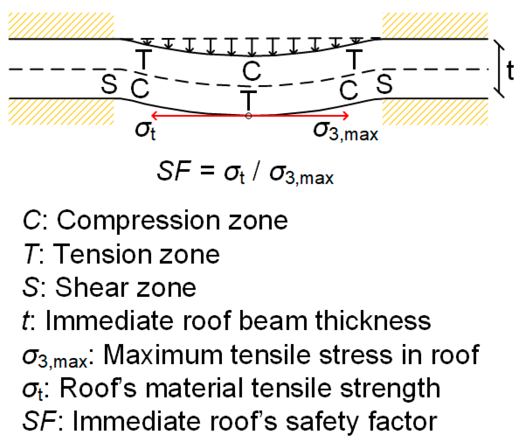
2.3. Safety Definition

Typically, the stability of the underground openings in mining operations is governed by the safety conditions of the roofs, which are primarily controlled by the distribution of tensile and compressive stresses upon them and the in-situ stress conditions [2,4]. The compressive strength of rock is generally an order of magnitude greater than its tensile strength; thus, tension failure is more frequent than compressive failure. Furthermore, the maximum applied compressive stresses are located in the room abutments, and the pillars undertake a remarkable amount of compressive load. As a result, the critical failure mechanism of the mining openings is most frequently associated with the tensile failure of the immediate roof [2] due to excessive bending in the middle of its span [1].
In that case, the initiation of instability is typically related to a tensile failure mechanism of the immediate roof that can propagate and cause further deformations in the soil layers above the opening. The same concept was investigated in the present case, where a sandstone layer directly overlies the underground openings (see Figure 1). Figure 3 conceptualizes the immediate roof’s tensile failure mechanism related to the roof’s excessive bending. Failure of the immediate roof’s layer results in the overburden strata overload, which cannot sustain the excessive load and fail. The overburden materials subsequently flow into the voids, eventually leading to the formation of a sinkhole on the surface due to the small openings’ depth.
In this work, the safety of the openings was defined on the mechanism described above based on the initiation of the bending failure using elementary statics and stress analysis. The immediate roof can be considered as a beam fixed at both ends loaded transversely to its axis [2]. As a result, the shear force is maximum at the ends of the beam (in the area of the room’s side abutments) and zero in the middle of it. In terms of stresses, the lower section of the beam’s middle area presents the maximum tensile stress (for the symmetrical definition herein used), where the bending failure typically initiates (Figure 4). The safety is then defined as the ratio of the tensile strength (σt) to the maximum tensile stress applied to the roof (σ3,max):
S F = σ t σ 3 , m a x
In case of overloading the roof in tension, indicated by a Safety Factor (SF) lower than unity (SF < 1), the opening should be considered unstable. The above SF is systematically used to quantify the shallow underground mine’s stability. It can also be used indirectly to assess the potential for sinkhole occurrence based on additional factors, as described before. This instability may coincide with the initiation of a progressive failure mechanism that advances upwards and intercepts the ground surface as the overburden materials cave into failed openings. Therefore, the safety of the opening’s roof, as defined above, can be considered directly related to the potential for sinkhole formation.

3. Results and Discussion

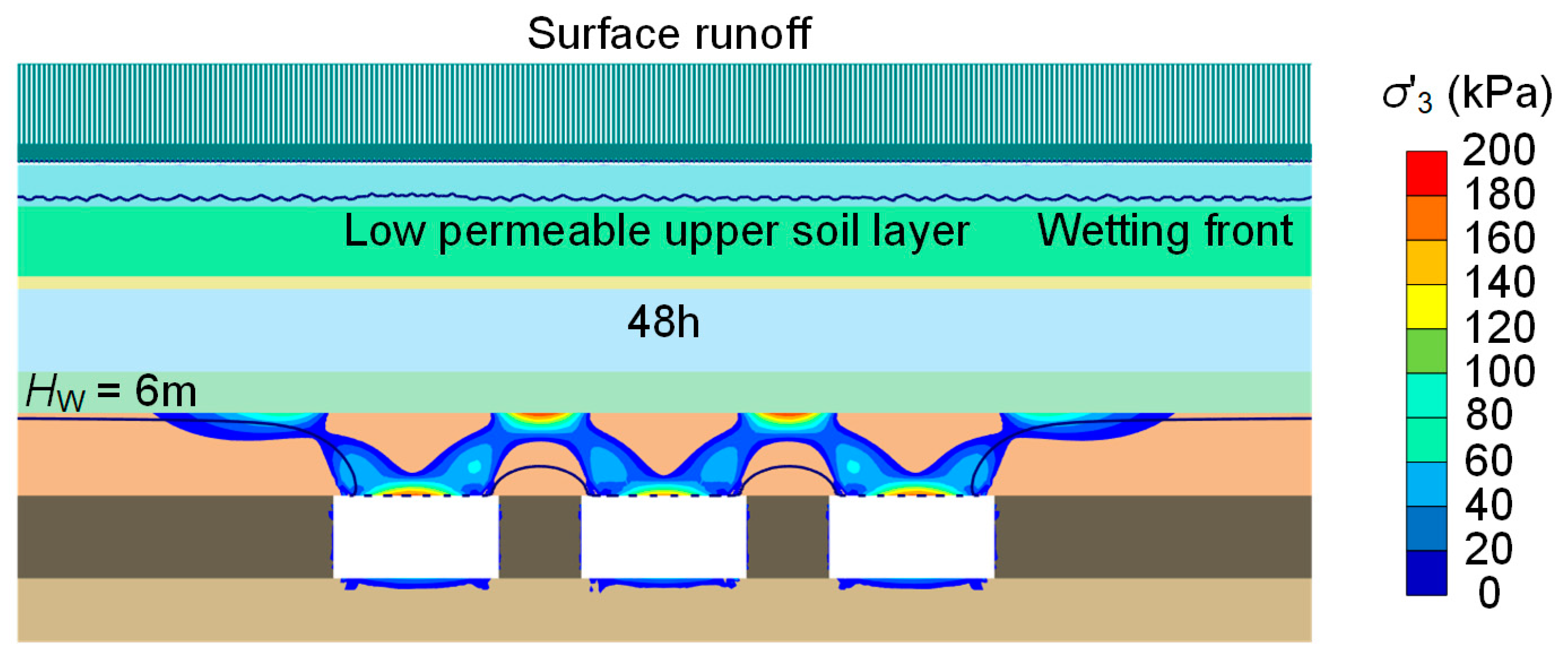
3.1. Individual Rainfall Event

The short-term modeling approach aimed to investigate the stability and potential for sinkhole formation in shallow underground openings due to significant individual rainfall events. A groundwater level at the identified phreatic line was employed 6 m below the surface (Hw = 6 m). The analysis focused on the evolution of the minor principal stress (σ3) at the middle of the span of the roof of the openings, as it was crucial for the defined safety factor (see Equation (4)).
Figure 5 illustrates the contours of the effective minor principal stress σ3 in the immediate roof of the underground openings (positive values define tension). These stresses represent the effective tensile stresses concentrated in the middle of the sandstone roof’s span due to bending development in this area. Tensile stresses developed in the form of an arch within the sandstone roof surrounding the openings, providing the confinement needed to support the overburden loading. Thus, the development of this stress distribution was beneficial for the safety of the formed underground openings, providing that their maximum values did not exceed the tensile strength of the roof material (σ3,max < σt, SF > 1).
A fully coupled analysis was conducted with the rainfall evolution within the soil. After 48 h of rainfall, the wetting front advanced for just a single meter underneath the ground surface. This slow advancement of the wetting front was attributed to the upper silty-clay layer with low permeability (5 ∙ 10−6 cm/s), leading to forming the perched water above this aquitard. That layer notably inhibited the infiltration of rainwater into the ground. Therefore, due to the difficulty of the stormwater to considerably infiltrate within the ground after the individual rainfall incident, the initial phreatic line (located 6 m below the ground surface) remained unchanged. Thus, the individual rainfall event did not alter the stress field around the opening, so the stability of the underground voids was unchangeable due to the rainfall event. Overall, the underground stability was not influenced by this individual rainfall event.
An additional rainfall scenario of the same intensity with a longer duration—4 days instead of 2—was also applied. The wetting front had practically advanced similarly to the two days’ duration scenario, and only a marginally more extended dissipation of the suction had been propagated into the lower soil strata. However, this slightly extended dissipation had not impacted the immediate roof sandstone layer and the development of stress distribution.
This outcome underlines the perception that the stability of the underground openings, due to the effect of water, is principally related to the long-lasting groundwater recharge, which stems from multiple accumulated rainfall incidents in the long term [8,22]. However, the above outcome should be considered under the context of the examined case study and the specific prevailing conditions presented at that particular site. An individual rainfall event might adversely affect the openings’ safety for a different stratigraphy with highly permeable soil upper layers (if there is no perched water above an aquitard made of low permeability layers).

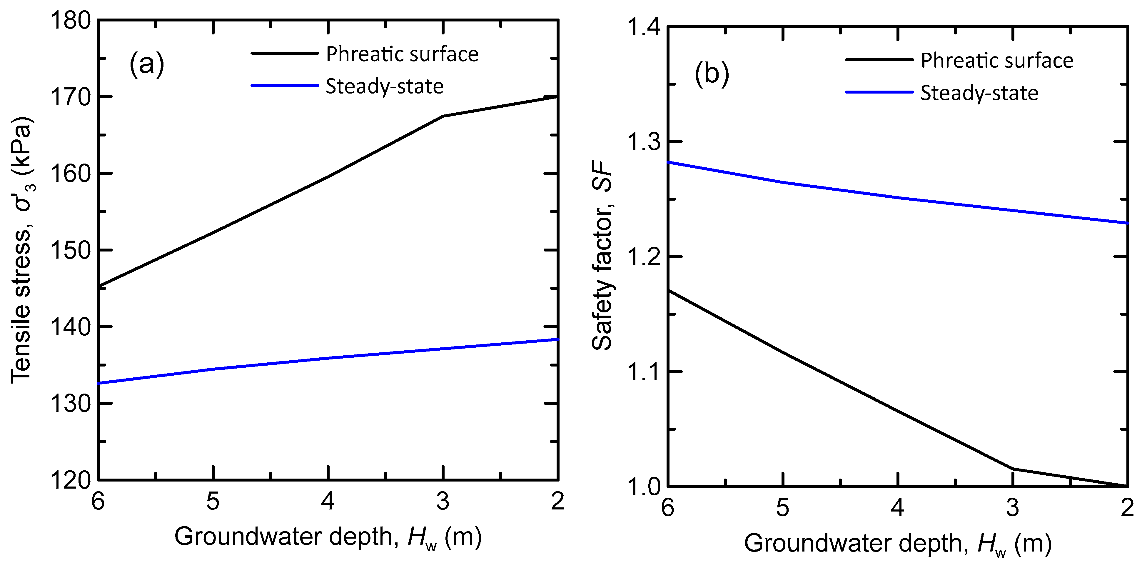
3.2. Groundwater Recharge

The long-term modeling approach indirectly considers the accumulated effect of several rainfall events leading to groundwater recharge. This effect was simulated by a considerable rise of the groundwater table that deteriorated the shallow underground openings’ stability and consequently increased the probability of sinkhole formation. The results are on the conservative side but provide trends and quantify the effect of groundwater. The calculations of the porewater pressures and, subsequently, of the effective stresses above the openings were based on a description of the groundwater state that, in practice, was unknown. In that vein, two approaches were followed based on two types of boundary conditions: (a) the phreatic line with hydrostatic conditions (named the phreatic line in the sequel for brevity), and (b) steady-state flow. In the first case (a), a horizontal constant groundwater pressure head was defined at the level of the phreatic line, and hydrostatic porewater pressures were subsequently calculated. In the second case (b), a constant groundwater pressure head was defined on the vertical (left and right) boundaries of the model, and porewater pressures in the model were calculated by steady-state flow. In both cases, the long-term groundwater recharge was reproduced by the gradual rise of the phreatic surface, either through an elevated phreatic line or by the definition of appropriate boundary conditions at the model’s external boundaries with steady-state flow. The initial conditions are presented in Figure 5 for the phreatic line; a similar stress distribution but with lower values was the case for the steady-state flow analysis.
Figure 6 illustrates the evolution of the safety factor (SF) with the rise of the groundwater table in both cases. As the groundwater table increased (groundwater depth decreased), the minor principal effective stress (σ3), which is the horizontal tensile stress responsible for the safety of the opening, increased. As a result, the SF decreased, as was expected, due to the groundwater recharge. There was a difference in the initial state at the stress σ3 and the SF for the two boundary conditions (phreatic line and steady-state) due to the differences in the pore pressure calculation; more details on the porewater pressures are discussed in the following. However, in both cases, the initial and final SFs are close to 1, denoting possible instability. The groundwater recharge had a more dramatic influence on the phreatic line case (SF from 1.18 to 1); for the steady-state, there was a smaller change from 1.28 to 1.23. The phreatic line was a conservative approach that denotes that such a groundwater recharge could lead to instability and sinkhole potential.
As the groundwater level rose, the σ3—denoting tension—increased. In simplified terms, the increase can be seen as the effect of the total weight on top of the roof of the opening that increased with the rise of the groundwater table. As a result, a higher load was applied to the roof that bent, and the horizontal stress σxx (equal to σ3) increased (see Figure 4). In practice, the porewater pressures in the soil and rock layers were critical for the evolution of the horizontal (σxx = σ3) and vertical (σyy = σ1) effective stresses at that point. Thus, as the groundwater level rose and the porewater pressures evolved, the soil unit weight changed from unsaturated (γ) to saturated (γsat), and the horizontal and vertical effective stresses at the roof also rose.
In the final recharge stage in the phreatic line analysis, where the groundwater surface had been raised two meters beneath the ground surface (Hw = 2 m), the SF became 1. Figure 7a illustrates the distribution of minor principal effective stresses around the underground openings at this state; these were all tensile stresses (positive values denote tension). The σ3 coincided with the cartesian normal stress σxx at the mid-bottom of the roof span because of the absent shear stress at the same point (see Figure 3 and Figure 4). Figure 7b presents the distribution of the effective tensile stresses around the underground rooms for the steady-state flow boundary condition. The stress distributions for the two cases were very similar. A significant stress concentration is presented in the middle of the immediate roof. However, the magnitude of the effective tensile stresses was remarkably different due to the consideration of the critical effect of the groundwater.
This difference was attributed to the difference in groundwater evaluation. Very high porewater pressures exist at the immediate sandstone roof above the opening for the phreatic line (see Figure 8a, uw = 59.4 kPa). Meanwhile, almost zero porewater pressures were presented for the steady-state flow analysis (see Figure 8b, uw = 1.3 kPa). Figure 8b presents the porewater pressure distribution on the vertical boundaries very close to the openings; note that the total model was much wider (see Figure 2), and no boundary conditions arose. For the steady-state flow conditions, the openings defined conditions with zero porewater pressure and thus edges and roofs with very small porewater pressures. On the other side, an important hydrostatic pressure developed on the roof for the phreatic line. Both of these conditions represent limit conditions and are practically the limits of this analysis.
Figure 9 presents the evolution of porewater pressures with the groundwater table level rise (decreasing groundwater depth Hw) during the groundwater recharge for the two approaches. The porewater pressures computed by the phreatic line approach increased notably with the groundwater rising; practically, hydrostatic conditions denote a significant pressure due to a higher water depth. Instead, for steady-state groundwater flow, only a slight rise in the porewater pressures was noticed as the opening was defined as dry and the roof had practically zero water pressure. The seepage flow that develops above and towards the voids notably inhibited the build-up of porewater pressures in the area of the immediate roof. Consequently, the zero pore pressures in the middle lower part of the immediate roof remained practically unchanged.
The instability of the roof and the failure mechanism may be presumed to transmit upwards, considering that the overburden soil strata could not inhibit the development of large deformations and settlements due to their geological conditions. The caving of the overburden soil into the mining openings highlights the potential for sinkhole occurrence due to groundwater recharge in the long term. Figure 10 presents the additionally developed settlements at the end of the groundwater recharge through a scaled-up deformed finite element mesh. At the final stage of the groundwater rising, where the phreatic surface was two meters below the ground surface, concentrated settlements were noticed on the sandstone roof. This roof deflection illustrates the bending nature of the loading on the roof, leading to tensional instability (SF = 1). This instability might, in turn, also induce the flow of the soil cover into the voids, accompanied by the formation of a sinkhole.

4. Conclusions

This work examined the effect of groundwater recharge on the stability of a room-and-pillar underground mining void. A specific stratigraphy was analyzed where the instability of the opening could potentially lead to the formation of a sinkhole, given the geological conditions, the overburden stratigraphy, and the depth of the openings. The groundwater recharge was investigated as an individual rainfall infiltration (short-term approach) and as groundwater dynamics (long-term approach) with two approaches for the porewater pressure calculation: (a) phreatic line with hydrostatic conditions and (b) steady-state flow based on free field boundary conditions. The safety analysis was based on the bending of the roof of the underground opening, and numerical analysis was employed to obtain the stress distribution. The major conclusions are as follows:
(1)
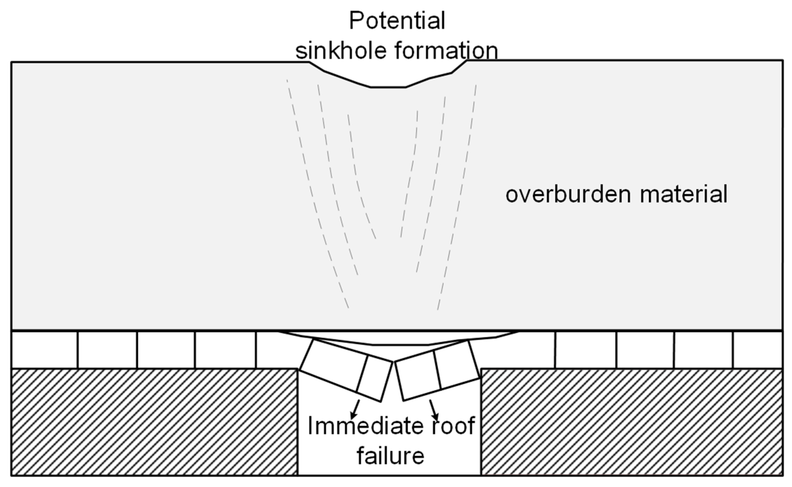
The short-term safety remained unaffected by an individual rainfall event as a lowpermeability upper soil layer (silty clay) limited rainfall’s infiltration into the materials surrounding the underground openings to form perched water above an aquitard.
(2)
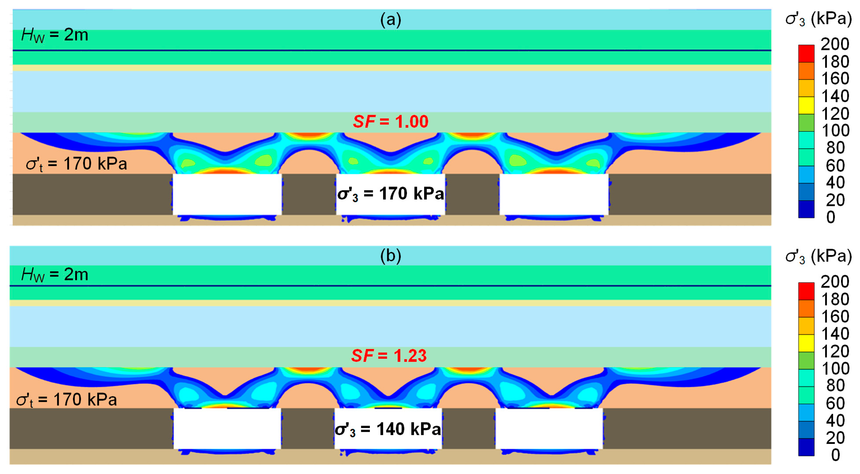
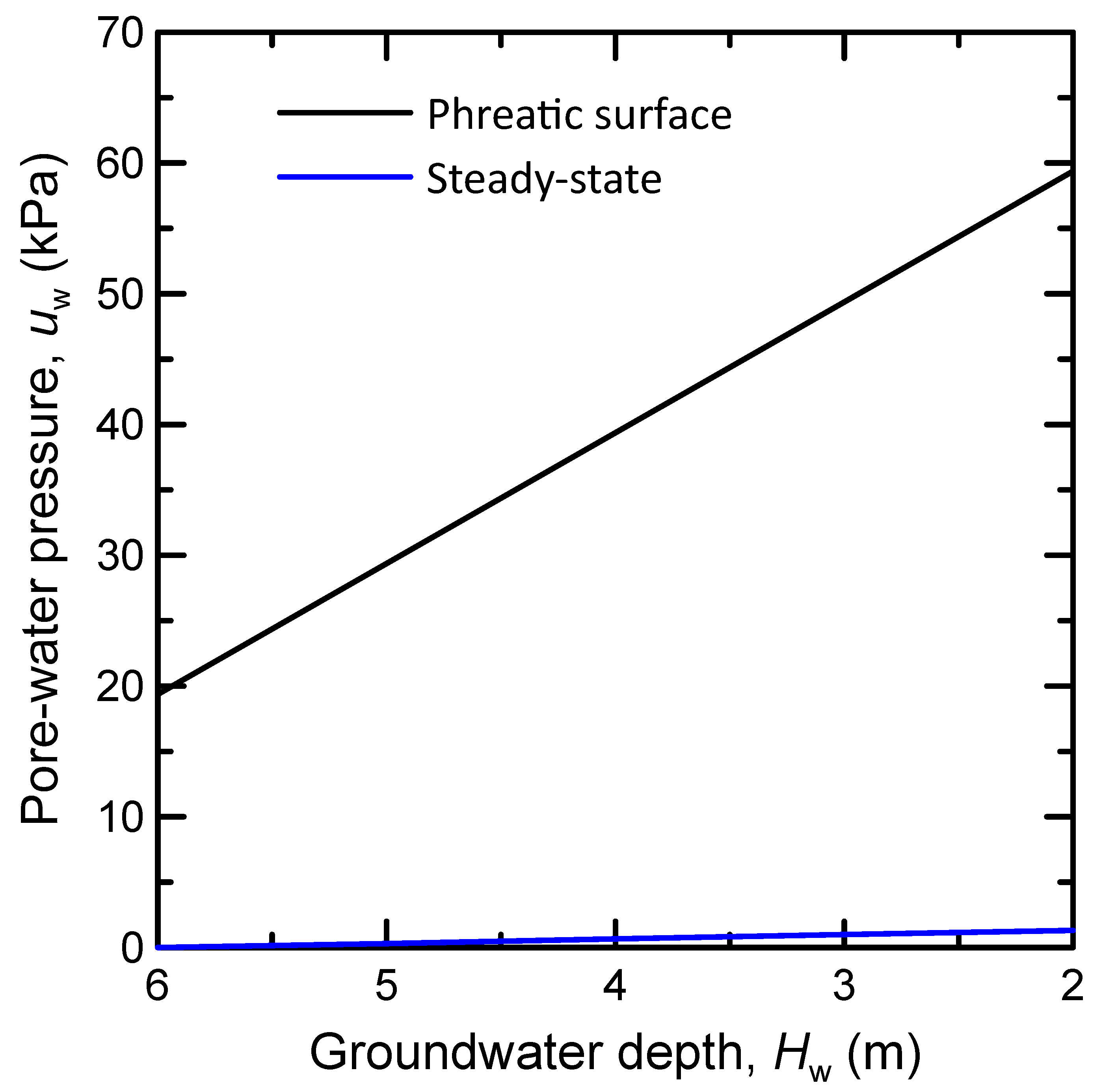
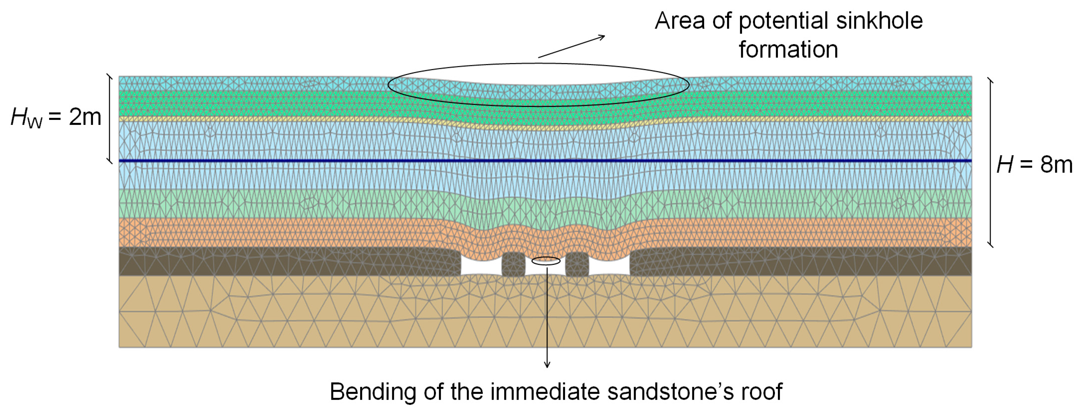
The long-term safety deteriorated when considering the gradual recharge of groundwater, representing the accumulation of infiltrated stormwater from several rainfall events. This decrease in the safety factor was due to the increase of the tensile stresses in the roof of the underground openings with the rise of the groundwater table for both examined approaches for porewater pressure calculation limits (phreatic line versus steady-state flow).
(3)
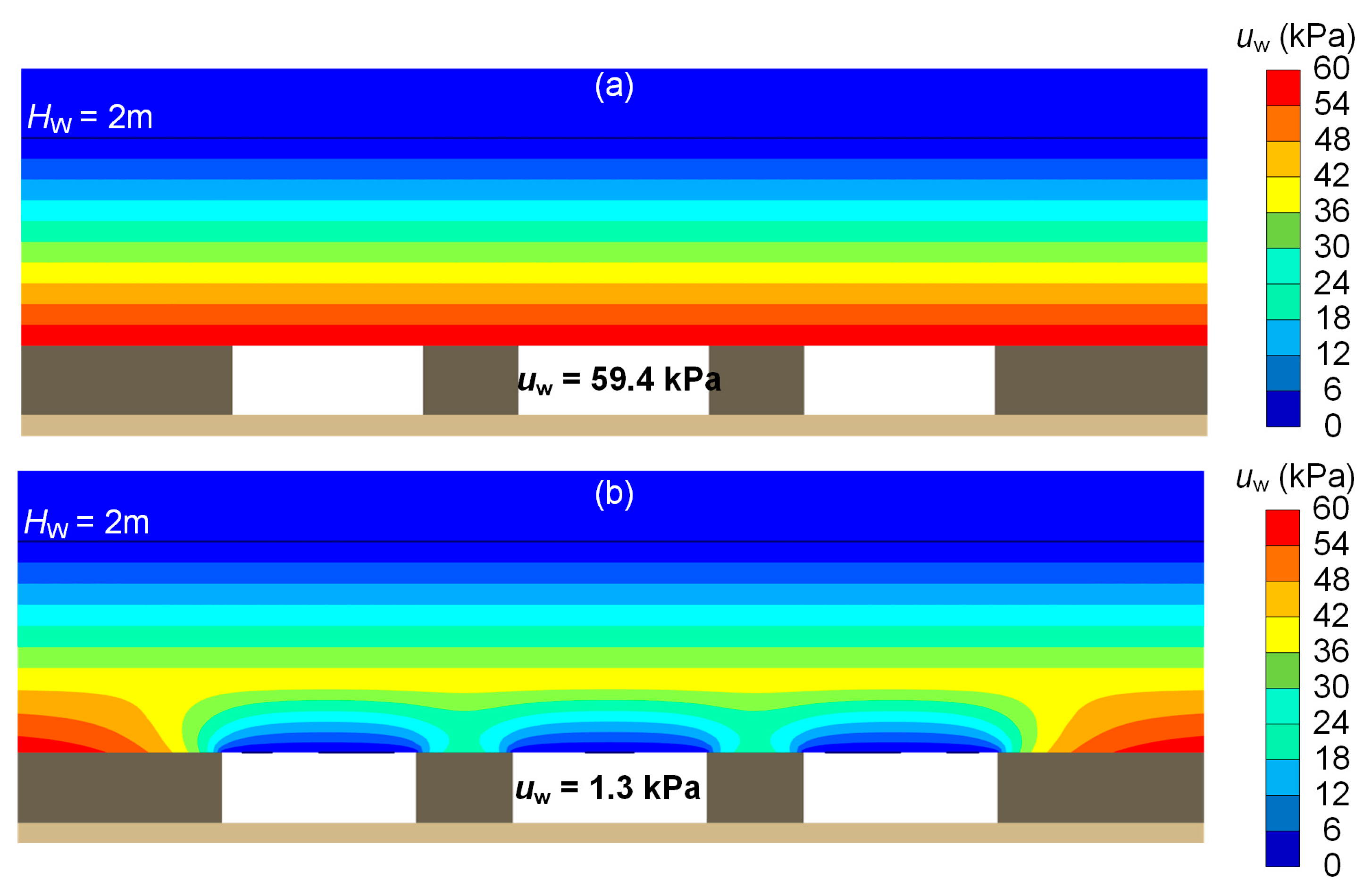
The phreatic line approach is the most conservative, resulting in lower safety factors than the steady-state flow analysis due to the build-up of higher hydrostatic pressure on the roof of the opening.
(4)
The steady-state analysis provided smaller tensile stresses on the opening’s roof due to groundwater flow conditions. In this case, the porewater pressure inside the openings was, by definition, zero and very small at the openings’ edges and roofs.

Author Contributions

Conceptualization, I.E.Z. and N.C.K.; methodology, I.E.Z. and A.I.T.; software, A.I.T. and A.V.D.; validation, I.E.Z. and A.I.T.; investigation, A.V.D. and I.E.Z.; resources, I.E.Z. and N.C.K.; data curation, A.I.T. and A.V.D.; writing—original draft preparation, A.V.D. and A.I.T.; writing—review and editing, I.E.Z., N.C.K. and A.I.T.; visualization, A.V.D. and A.I.T.; supervision, I.E.Z. and N.C.K.; project administration, I.E.Z. and N.C.K.; funding acquisition, I.E.Z. and N.C.K. All authors have read and agreed to the published version of the manuscript.

Funding

This work was funded by the European Union’s Research Fund for Coal and Steel under the project TEXMIN grant agreement No. 847250 and the project RAFF grant agreement No. 847299. Financial assistance from the European Commission is greatly appreciated.

Data Availability Statement

Not applicable.

Conflicts of Interest

The authors declare no conflict of interest.

Nomenclature

ceffective cohesion
EYoung’s modulus
gafitting parameter of the SWCC related to the air entry value
glfitting parameter of the SWCC equal to 0.5
gnfitting parameter of the SWCC governing its shape that is a function of the rate of water extraction from the soil once the air entry value has been exceeded
GWTgroundwater table
Hpheight of the coal layer
Hwgroundwater depth
kspermeability coefficient
kwunsaturated soil permeability coefficient
qrainfall intensity
SFSafety Factor
Seeffective soil saturation
Srresidual soil saturation
Sssoil saturation at the fully saturated state
Swsaturation degree
uwporewater pressure
γmoist soil unit weight
γsatsaturated soil unit weight
γwunit weight of water equal to 9.81 kN/m3
νPoisson ratio
σ’yyvertical effective stress
σttensile strength
σ’xxhorizontal effective stress
φeffective friction angle
ψdilation angle

References

  1. Whittaker, B.N.; Reddish, D.J. Subsidence: Occurrence, Prediction and Control; Elsevier Science Publishers B.V.: Amsterdam, The Netherlands, 1989. [Google Scholar]
  2. Galvin, J. Ground Engineering-Principles and Practices for Underground Coal Mining; Springer International Publishing: London, UK, 2016. [Google Scholar]
  3. Karfakis, M.G. Residual Subsidence Over Abandoned Coal Mines. In Surface and Underground Project Case Histories; Hoek, E., Ed.; Pergamon: Oxford, UK, 1993; pp. 451–476. [Google Scholar]
  4. Brady, B.H.; Brown, E.T. Rock Mechanics: For Underground Mining; Springer International Publishing: London, UK, 2006. [Google Scholar]
  5. Singh, K. Causes and remedial measures of pot-hole subsidence due to coal mining. J. Sci. Ind. Res. 2000, 59, 280–285. [Google Scholar]
  6. Karfakis, M.G. Chimney subsidence over abandoned coal mines. Int. J. Min. Geol. Eng. 1987, 5, 131–141. [Google Scholar] [CrossRef]
  7. Singh, K.B.; Dhar, B.B. Sinkhole subsidence due to mining. Geotech. Geol. Eng. 1997, 15, 327–341. [Google Scholar] [CrossRef]
  8. Canbulat, I.; Zhang, C.; Black, K.; Johnston, J.; McDonald, S. Assessment of sinkhole risk in shallow coal mining. In Proceedings of the 10th Triennial Conference on Mine Subsidence, Pokolbin, Australia, 5–7 November 2017; pp. 331–337. [Google Scholar]
  9. Hood, M.; Ewy, R.T.; Riddle, L.R. Empirical methods of subsidence prediction—A case study from Illinois. Int. J. Rock Mech. Min. Sci. Geomech. Abstr. 1983, 20, 153–170. [Google Scholar] [CrossRef]
  10. O’Rourke, T.; Turner, S. Empirical methods for estimating subsidence in US coal fields. In Proceedings of the 22nd US Symposium on Rock Mechanics (USRMS), Cambridge, MA, USA, 22–24 June 1981. [Google Scholar]
  11. Goel, S.C.; Page, C.H. An empirical method for predicting the probability of chimney cave occurence over a mining area. Int. J. Rock Mech. Min. Sci. Geomech. Abstr. 1982, 19, 325–337. [Google Scholar] [CrossRef]
  12. Drumm, E.C.; Kane, W.F.; Yoon, C.J. Application of limit plasticity to the stability of sinkholes. Eng. Geol. 1990, 29, 213–225. [Google Scholar] [CrossRef]
  13. Xu, D.; Peng, S.; Xiang, S.; Liang, M.; Liu, W. The Effects of Caving of a Coal Mine’s Immediate Roof on Floor Strata Failure and Water Inrush. Mine Water Environ. 2016, 35, 337–349. [Google Scholar] [CrossRef]
  14. Strzałkowski, P.; Litwa, P. Environmental protection problems in the areas of former mines with emphasis on sinkholes: Selected examples. Int. J. Environ. Sci. Technol. 2021, 18, 771–780. [Google Scholar] [CrossRef]
  15. Alejano, L.; Ramírez-Oyanguren, P.; Taboada, J. FDM predictive methodology for subsidence due to flat and inclined coal seam mining. Int. J. Rock Mech. Min. Sci. 1999, 36, 475–491. [Google Scholar] [CrossRef]
  16. Helm, P.R.; Davie, C.T.; Glendinning, S. Numerical modelling of shallow abandoned mine working subsidence affecting transport infrastructure. Eng. Geol. 2013, 154, 6–19. [Google Scholar] [CrossRef] [Green Version]
  17. Najjar, Y.; Zaman, M. Surface Subsidence Prediction by Nonlinear Finite Element Analysis. J. Geotech. Eng. 1993, 119, 1790–1804. [Google Scholar] [CrossRef]
  18. Salmi, E.F.; Karakus, M.; Nazem, M. Assessing the effects of rock mass gradual deterioration on the long-term stability of abandoned mine workings and the mechanisms of post-mining subsidence—A case study of Castle Fields mine. Tunn. Undergr. Space Technol. 2019, 88, 169–185. [Google Scholar] [CrossRef]
  19. Khadka, S.; Wang, Z.-M.; Hu, L.-B. Exploring a Coupled Approach to Model the Geomechanical Processes of Sinkholes. In Proceedings of the GeoShanghai 2018 International Conference: Geoenvironment and Geohazard, Shanghai, China, 27–30 May 2018; GSIC 2018. Springer: Singapore, 2018; pp. 99–107. [Google Scholar]
  20. Salmi, E.F.; Nazem, M.; Karakus, M. The effect of rock mass gradual deterioration on the mechanism of post-mining subsidence over shallow abandoned coal mines. Int. J. Rock Mech. Min. Sci. 2017, 91, 59–71. [Google Scholar] [CrossRef]
  21. Poulsen, B.A.; Shen, B. Subsidence risk assessment of decommissioned bord-and-pillar collieries. Int. J. Rock Mech. Min. Sci. 2013, 60, 312–320. [Google Scholar] [CrossRef]
  22. Prakash, A.; Lokhande, R.; Singh, K. Impact of rainfall on residual subsidence in old coal mine workings. J. Environ. Sci. Eng. 2010, 52, 75–80. [Google Scholar]
  23. Singh, K. Pot-hole subsidence in Son-Mahanadi master coal basin. Eng. Geol. 2007, 89, 88–97. [Google Scholar] [CrossRef]
  24. Lu, N.; Likos, W.J. Unsaturated Soil Mechanics; John Wiley & Sons: Hoboken, NJ, USA, 2004. [Google Scholar]
  25. Fredlund, D.G.; Rahardjo, H. Soil Mechanics for Unsaturated Soils; John Wiley & Sons: Hoboken, NJ, USA, 1993. [Google Scholar]
  26. Bear, J. Dynamics of Fluids in Porous Media; American Elsevier Publishing Company, Inc.: New York, NY, USA, 1972. [Google Scholar]
  27. Diamantopoulos, E.; Durner, W. Dynamic Nonequilibrium of Water Flow in Porous Media: A Review. Vadose Zone J. 2012, 11, vzj2011-0197. [Google Scholar] [CrossRef]
  28. Hu, R.; Chen, Y.-F.; Liu, H.-H.; Zhou, C.-B. A water retention curve and unsaturated hydraulic conductivity model for deformable soils: Consideration of the change in pore-size distribution. Géotechnique 2013, 63, 1389–1405. [Google Scholar] [CrossRef]
  29. Yan, G.; Bore, T.; Schlaeger, S.; Scheuermann, A.; Li, L. Investigating scale effects in soil water retention curve via spatial time domain reflectometry. J. Hydrol. 2022, 612, 128238. [Google Scholar] [CrossRef]
  30. Yan, G.; Li, Z.; Bore, T.; Galindo Torres, S.A.; Scheuermann, A.; Li, L. A lattice Boltzmann exploration of two-phase displacement in 2D porous media under various pressure boundary conditions. J. Rock Mech. Geotech. Eng. 2022, 14, 1782–1798. [Google Scholar] [CrossRef]
  31. Hu, R.; Lan, T.; Wei, G.-J.; Chen, Y.-F. Phase diagram of quasi-static immiscible displacement in disordered porous media. J. Fluid Mech. 2019, 875, 448–475. [Google Scholar] [CrossRef]
  32. Carsel, R.F.; Parrish, R.S. Developing joint probability distributions of soil water retention characteristics. Water Resour. Res. 1988, 24, 755–769. [Google Scholar] [CrossRef]
  33. Zhang, L.; Fredlund, D.; Zhang, L.; Tang, W. Numerical study of soil conditions under which matric suction can be maintained. Can. Geotech. J. 2004, 41, 569–582. [Google Scholar] [CrossRef]
  34. Lin, H.; Zhong, W. Influence of Rainfall Intensity and Its Pattern on the Stability of Unsaturated Soil Slope. Geotech. Geol. Eng. 2019, 37, 615–623. [Google Scholar] [CrossRef]
  35. Kim, J.; Jeong, S.; Regueiro, R.A. Instability of partially saturated soil slopes due to alteration of rainfall pattern. Eng. Geol. 2012, 147, 28–36. [Google Scholar] [CrossRef]
  36. Mualem, Y. A new model for predicting the hydraulic conductivity of unsaturated porous media. Water Resour. Res. 1976, 12, 513–522. [Google Scholar] [CrossRef] [Green Version]
  37. Van Genuchten, M.T. A closed-form equation for predicting the hydraulic conductivity of unsaturated soils. Soil Sci. Soc. Am. J. 1980, 44, 892–898. [Google Scholar] [CrossRef] [Green Version]
  38. Plaxis 2D Finite Element Geotechnical Analysis Software, V20.3; Bentley: Dublin, Ireland, 2020.
  39. Jaky, J. Pressure in silos. In Proceedings of the 2nd International Conference on Soil Mechanics and Foundation Engineering, Rotterdam, The Netherlands, 21–30 June 1948; pp. 103–107. [Google Scholar]
  40. Plaxis. Material Models Manual; Bentley: Dublin, Ireland, 2020.
  41. Deliveris, A.V.; Benardos, A. Evaluating performance of lignite pillars with 2D approximation techniques and 3D numerical analyses. Int. J. Min. Sci. Technol. 2017, 27, 929–936. [Google Scholar] [CrossRef]
  42. Pariseau, W.; Sorensen, W. 3D mine pillar design information from 2D FEM analysis. Int. J. Numer. Anal. Methods Geomech. 1979, 3, 145–157. [Google Scholar] [CrossRef]
  43. Duncan Fama, M.E.; Trueman, R.; Craig, M.S. Two- and three-dimensional elasto-plastic analysis for coal pillar design and its application to highwall mining. Int. J. Rock Mech. Min. Sci. Geomech. Abstr. 1995, 32, 215–225. [Google Scholar] [CrossRef]
  44. Rahimi, A.; Rahardjo, H.; Leong, E.-C. Effect of hydraulic properties of soil on rainfall-induced slope failure. Eng. Geol. 2010, 114, 135–143. [Google Scholar] [CrossRef]
  45. Myhre, G.; Alterskjær, K.; Stjern, C.W.; Hodnebrog, Ø.; Marelle, L.; Samset, B.H.; Sillmann, J.; Schaller, N.; Fischer, E.; Schulz, M.; et al. Frequency of extreme precipitation increases extensively with event rareness under global warming. Sci. Rep. 2019, 9, 16063. [Google Scholar] [CrossRef] [PubMed]
  46. Fredlund, D.G. The 1999 R.M. Hardy Lecture: The implementation of unsaturated soil mechanics into geotechnical engineering. Can. Geotech. J. 2000, 37, 963–986. [Google Scholar] [CrossRef]
Figure 1. Typical geometry and stratigraphy of the shallow underground room and pillar coal mine.
Sustainability 15 00529 g001
Figure 2. Finite element discretization based on the initial stratigraphy (Hw groundwater depth, Hp height of the coal layer).
Sustainability 15 00529 g002
Figure 3. Tensile failure of the immediate roof and potential sinkhole formation.
Sustainability 15 00529 g003
Figure 4. Simplified model for roof stability due to bending.
Sustainability 15 00529 g004
Figure 5. Minor principal effective stresses after two days of rainfall.
Sustainability 15 00529 g005
Figure 6. Effect of groundwater recharge on (a) the minor principal effective stress in the middle of the roof span and (b) the safety factor.
Sustainability 15 00529 g006
Figure 7. Minor principal effective stresses after groundwater recharge: (a) phreatic line, and (b) steady-state flow.
Sustainability 15 00529 g007
Figure 8. Porewater pressures after groundwater recharge (a) phreatic line and (b) steady-state flow.
Sustainability 15 00529 g008
Figure 9. Pore pressures during groundwater recharge for the phreatic line and steady-state groundwater flow approaches.
Sustainability 15 00529 g009
Figure 10. Large ground settlements due to the bending of the roof of the underground openings (phreatic line analysis).
Sustainability 15 00529 g010
Table 1. Geotechnical properties of soil and rock layers.
Material
Parameters
γ (kN/m3)γsat (kN/m3)Ε
(MPa)
ν
(-)
c
(kPa)
φ
(deg)
ψ
(deg)
σt
(kPa)
ks
(cm/s)
Silty clay15.417.45.20.301138.5005 × 10−6
Silty sand15.417.4520.30230.5004 × 10−3
Sand, gravel, and clay16.218.2520.30335.5003 × 10−4
Silty gravel16.218.221.840.30329.5008 × 10−3
Glacial till16.218.2520.301029.5003 × 10−4
Sandstone (roof)25.026.043000.3436035.001704 × 10−3
Coal (pillar)15.015.046300.3346036.00230non-porous
Shale (floor)27.027.011,5500.30130043.00750non-porous
Table 2. Parameters of the unsaturated soil and rock materials.
Material ParametersSr (-)Ss (-)ga (1/m)gn (-)
Silty clay0.201.000.051.09
Silty sand0.151.001.242.28
Sand, gravel, and clay0.251.000.591.48
Silty gravel0.101.001.452.68
Glacial till0.251.000.271.23
Sandstone (roof)0.151.003.303.56
Disclaimer/Publisher’s Note: The statements, opinions and data contained in all publications are solely those of the individual author(s) and contributor(s) and not of MDPI and/or the editor(s). MDPI and/or the editor(s) disclaim responsibility for any injury to people or property resulting from any ideas, methods, instructions or products referred to in the content.

