Article

Failure Mechanism and Control Technology for Coal Roadway in Water-Rich Area

1
State Key Laboratory of Mining Response and Disaster Prevention and Control in Deep Coal Mines, Anhui University of Science and Technology, Huainan 232001, China
2
State Key Laboratory of the Gas Disaster Detecting Preventing and Emergency Controlling, China Coal Technology and Engineering Group Chongqing Research Institute, Chongqing 400037, China
3
Gas Research Branch, China Coal Technology and Engineering Group Chongqing Research Institute, Chongqing 400037, China
*
Author to whom correspondence should be addressed.
Sustainability 2023, 15(1), 410; https://doi.org/10.3390/su15010410
Submission received: 22 November 2022 / Revised: 14 December 2022 / Accepted: 22 December 2022 / Published: 27 December 2022

Abstract

:
Accurate analysis of failure mechanisms and scientific support for design of coal roadways in water-rich areas plays an important role in the long-term stability control of roadways. In this study, taking the water-rich 1044 return laneway in the Taoyuan Coal Mine of China as an example, laboratory experiments and field tests were performed to study the potential failure mechanisms of the roadway. It was found that the microcracks inside the coal body increase and strength of the coal decreases with the long-term influence of groundwater. The weak surrounding rock and high vertical in-situ stress were the main internal causes of roadway instabilities. Based on the potential failure mechanisms, a new optimal support design including bolt, cable, metal mesh, shotcrete, and grouting was proposed and detailed support parameters were introduced. A field experiment was performed with the new support, and surface deformations of the experimental roadway were monitored. Results show that the new support can reduce the deformation of the 1044 return laneway by nearly 90% compared with those of the original design. Support technology presented in this contribution provides a significant reference for the control of roadways in water-rich areas.

1. Introduction

Coal is one of the most widely used energy sources in the world [1,2]. There are a great number of roadways in a coal mine. Due to the diversity and complexity of geological conditions, the roadway is easily deformed, which seriously affects the safe and efficient mining of coal. Many engineering practices have shown that water-sensitive formations are a challenging problem that affects the stability of underground roadways in a coal mine, while reducing service life and reliability [3,4,5]. Therefore, it is of great significance to clarify the failure mechanisms and propose scientific control technology for roadways in water-rich areas.
In the past decades, numerous scholars have studied the failure mechanisms of water-rich roadways through theoretical analysis, laboratory tests and numerical simulation. Fan et al. [6] obtained an analytical solution for the post-peak zone radii and surface displacement for deep tunnels in considering the pore water pressure, and found that the tunnel deformation increases with the increase of pore water pressure. Shin et al. [7] studied the influence of seepage force on the ground reaction curve of underwater tunnels through theoretical analysis. Wang et al. [8] found that the roof collapse of shallow tunnels increases as the groundwater level drops. Zhang et al. [9] researched the effect of fluid-structure coupling on deformation characteristics of the surrounding rock from the weakening effect on physical and mechanical parameters of the rock mass. Tian et al. [10] studied the effect of groundwater in the coastal area on the deformation characteristics of the integrated pipe gallery through laboratory tests and MIDAS GTS/NX numerical simulation. Bhattacharya and Dutta [11] found that the seepage force during tunnel excavation reduced the stability of surrounding rock and increased the deformation. Wang et al. [12] researched the influence of groundwater on tunnel engineering, and found that collapse failure of the surrounding rock is more likely to occur with lower groundwater pressure. Taking the influence of groundwater seepage force into consideration, Shi et al. [13] analyzed the deformation and characteristic failures of underwater tunnels through numerical simulation. Pan et al. [14], Qin et al. [15], and Hao et al. [16] also explored the deformation and failure mechanisms of water-rich roadways through a series of studies.
A reasonable support design can effectively control the deformation of the roadway. Zhai et al. [17] proposed a novel double-seal deep and shallow inverted bottom arch floor support strategy for water-rich areas. A new grouting reinforcement method, “self-solution grouting reinforcement method,” was proposed by Lu et al. [18] to support underground works passing through water-rich soft rock. Lin et al. [19] found that the optimization of the roadway section, thin guniting of the roadway surface, optimization of support components, and gradient support could effectively reduce the deformation of soft rock roadway in water-rich area. Cheng et al. [20] proposed a joint control technology of grouting reinforcement floor heave based on floor blasting and pressure relief for the water-rich roadway in soft rock mass. Jiang et al. [21] found that a new support design including long cables, grouting, high pretensioning of bolts and cables, overbreak, and bolt-grouting backfill for the floor can maintain the long-term stability of soft rock roadway. Lu et al. [22] studied the mechanism of “yielding support” for anchor bolts and cables in the field, and results show that the new “highly resistant, yielding” support system adapts well to the deformation and pressure in the deep broken soft rock. Wang et al. [23] verified the reliability of advanced grouting, grouting bolts, and grouting anchor cables on a roadway in a fault zone. Ma et al. [24] developed a new support method for roadways in extremely soft rock based on high-strength bolt-beam-net, high density cable, and cable-grout technology. Based on the characteristics of high in-situ stresses and strong mining induced stresses suffered by coal mine roadways at 1000 m deep and above, Kang et al. [25] proposed a cooperative control technology considering bolting, grouting, and distressing. Wang et al. [26] proposed a new coupled bolting-grouting support technology based on grouting anchor cable and grouting bolt to relieve the deformation of soft rock roadway in a deep mine. Moreover, there are many other support technologies for roadways under different backgrounds [27,28,29,30].
The failure mechanisms and support designs of water-rich roadways under complicated conditions have been the focus of research in mining engineering. In this paper, based on the specific conditions of the 1044 return laneway in the Taoyuan Coal Mine in Anhui Province, China, a series of laboratory tests and field monitoring were performed to find out the potential failure mechanisms of the roadway. Then, a new optimal support was proposed and more scientific parameters were designed. Finally, the surface deformations of the roadway were monitored to test the reasonability of the new support.

2. Engineering Background

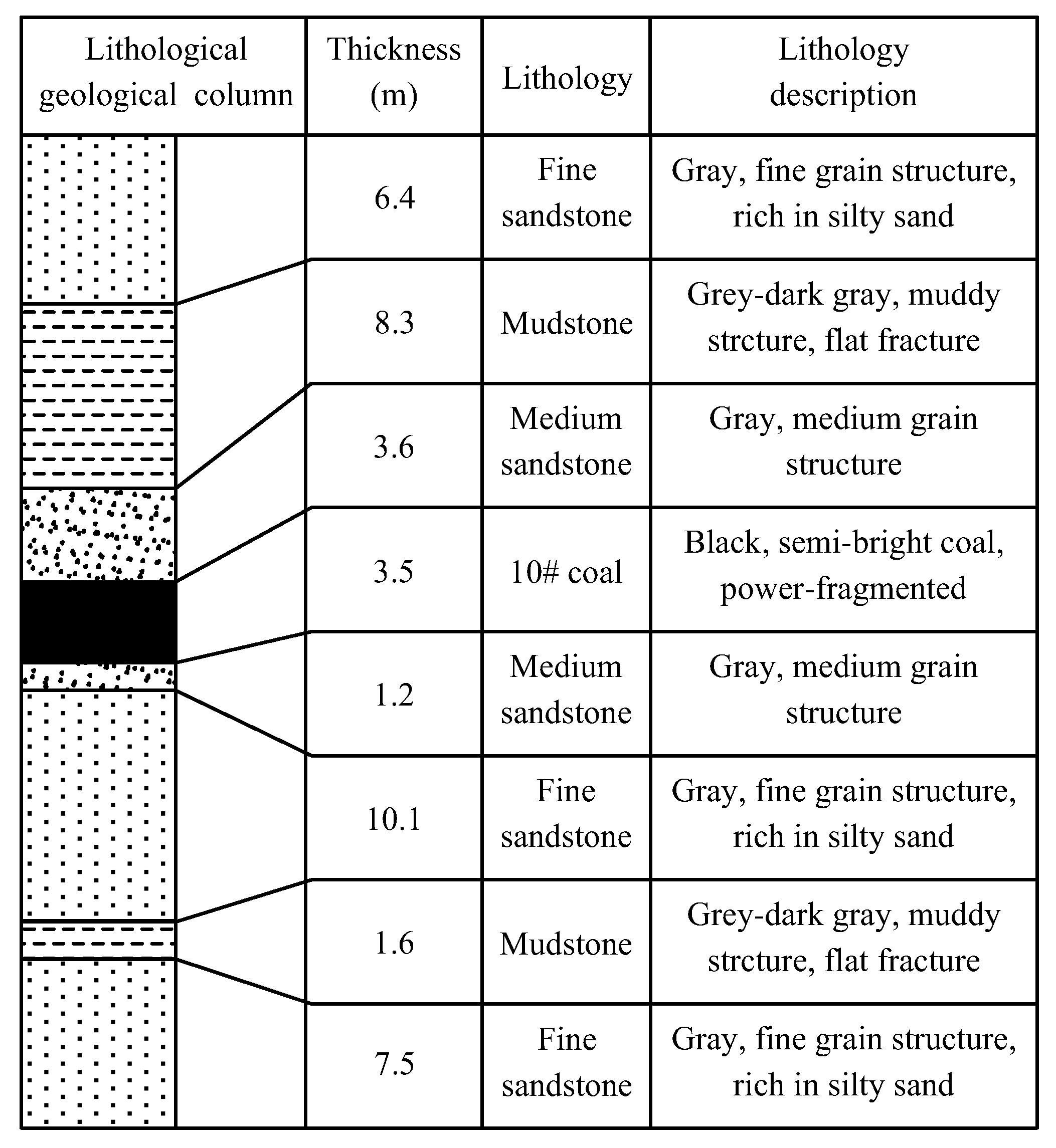
Taoyuan Coal Mine is located in the middle of Huaibei Plain in Anhui Province, amid flat terrain, mostly farmland, as shown in Figure 1a. The II4 mining area in the Taoyuan Coal Mine is located at −520 m~−800 m underground and +23 m~+25 m above the ground. The strike length of the mining area is about 2200 m, the dip width is about 900~1500 m, and the area is about 2.5 km2. The 1044 coalface adjacent to the 1042 coalface is the second working face in the II4 mining area (see Figure 1b), and there is only a 5.4 m-width coal pillar between the 1044 return laneway and the goaf of the 1042 coalface. The thickness of the coal seam is 2.5~4.3 m, with an average thickness of 3.5 m and dip angle of 28~44°, with an average angle of 35°. The roof of the coal seam is mudstone or fine sandstone, and the floor is mudstone. Figure 2 shows the strata histogram of the 10# coal seam.
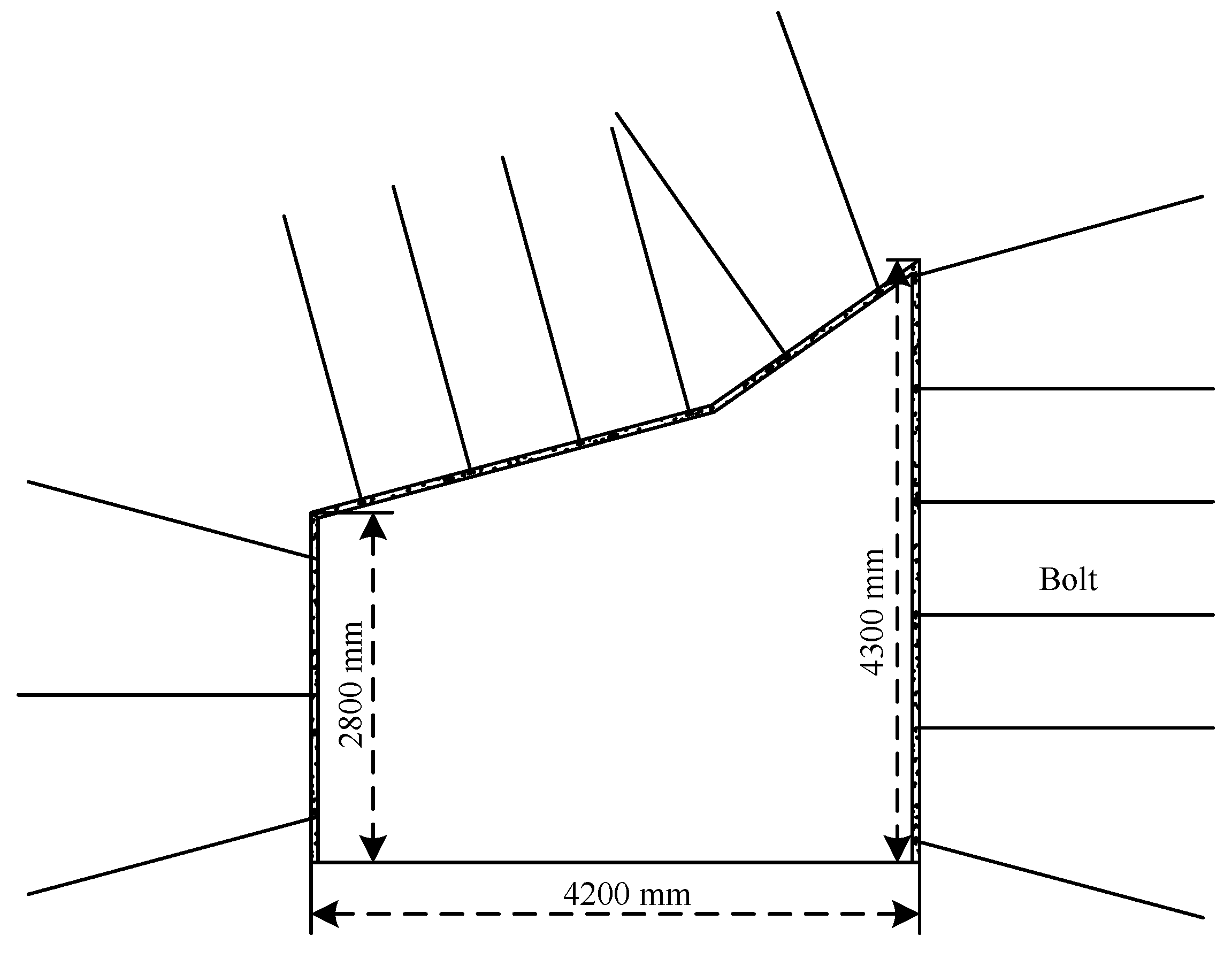
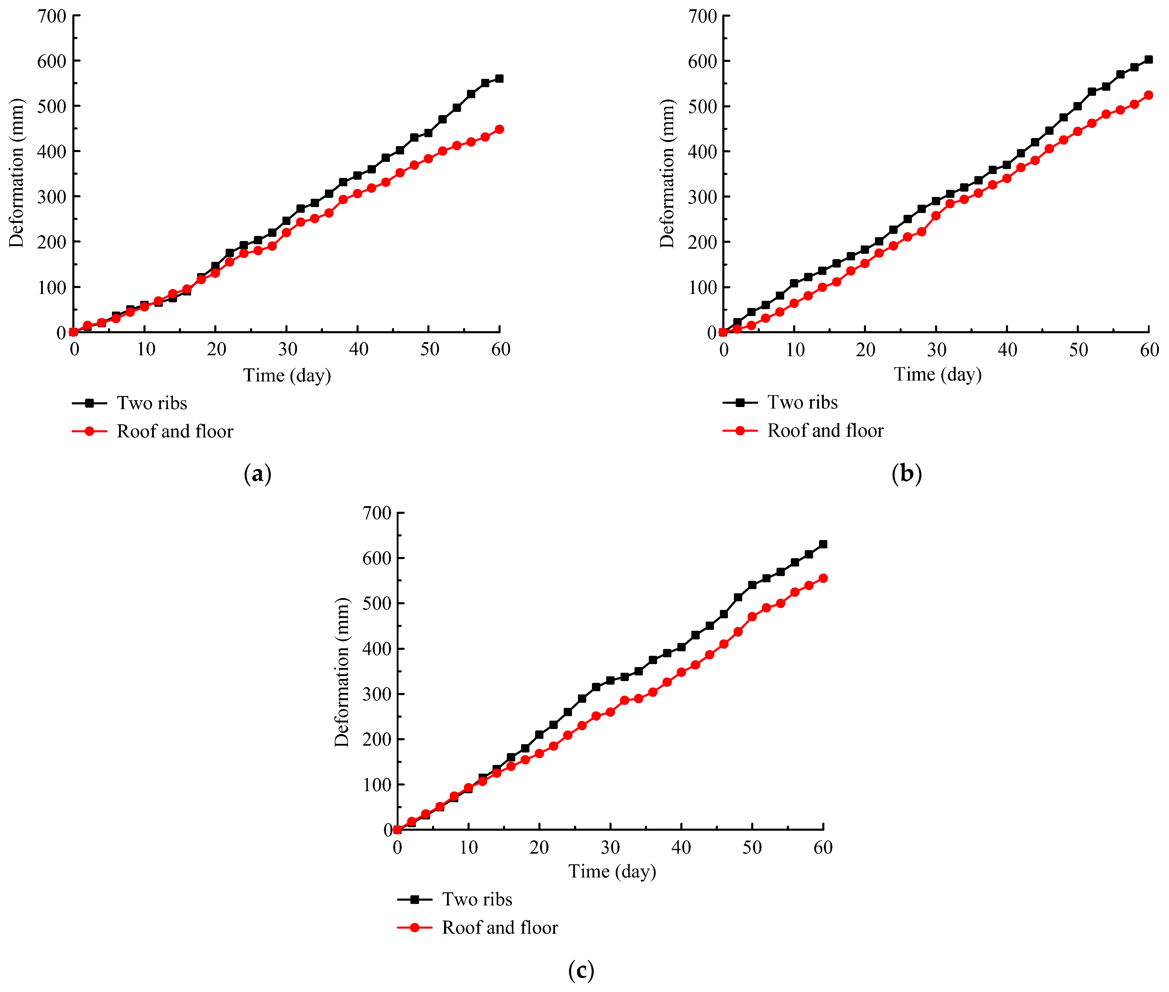
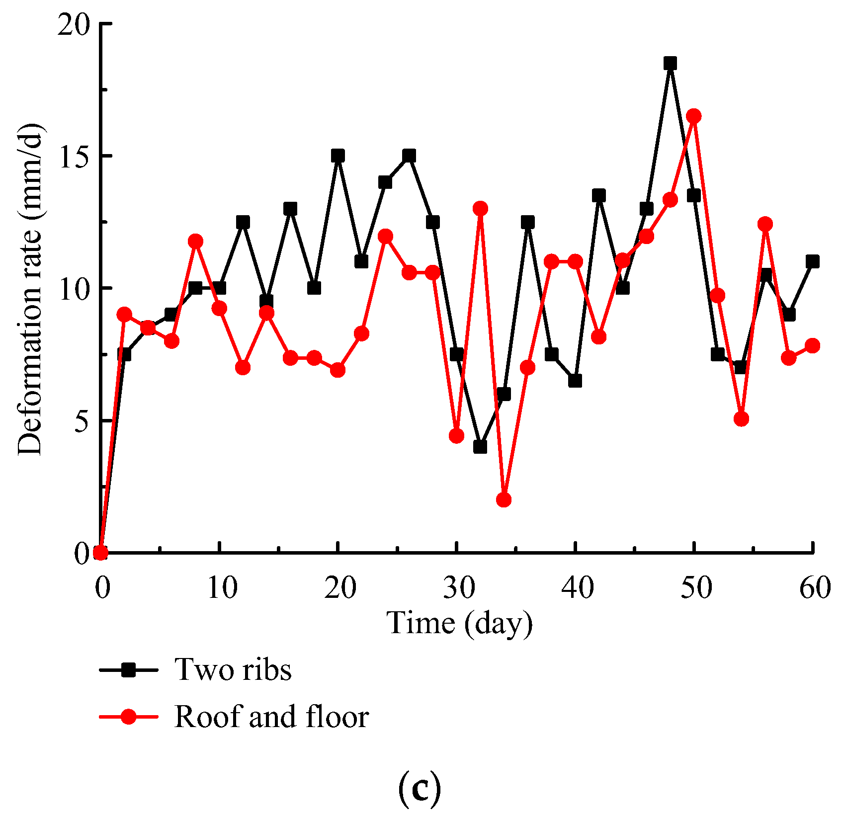
The buried depth of the 1044 return laneway was approximately 650 m. The cross section was like a right-angled trapezoid. The lower straight wall is 2.8 m high, the higher straight wall is 4.3 m high, and the roadway width is 4.2 m, as shown in Figure 3. During the excavation of 1044 return laneway, the normal water inflow is 5~10 m3/h, and the maximum water inflow can reach 20 m3/h. The water source is mainly from roof sandstone fissure water and goaf water of the 1042 coalface. Therefore, the 1044 return laneway is located in a water-rich area. Primarily, bolts combined with anchor cables and metal mesh were used as the permanent support to control the surrounding rock, as shown in Figure 3. Two months after excavation, the deformation of roof and floor reached 554 mm, the shrinkage of two ribs reached 629 mm, as shown in Figure 4, and the maximum deformation rate was still greater than 10 mm/d, as shown in Figure 5. Therefore, it is urgent to thoroughly study the failure mechanisms and optimize a support design.

3. Failure Mechanism Analyses

3.1. Microscopic Pattern

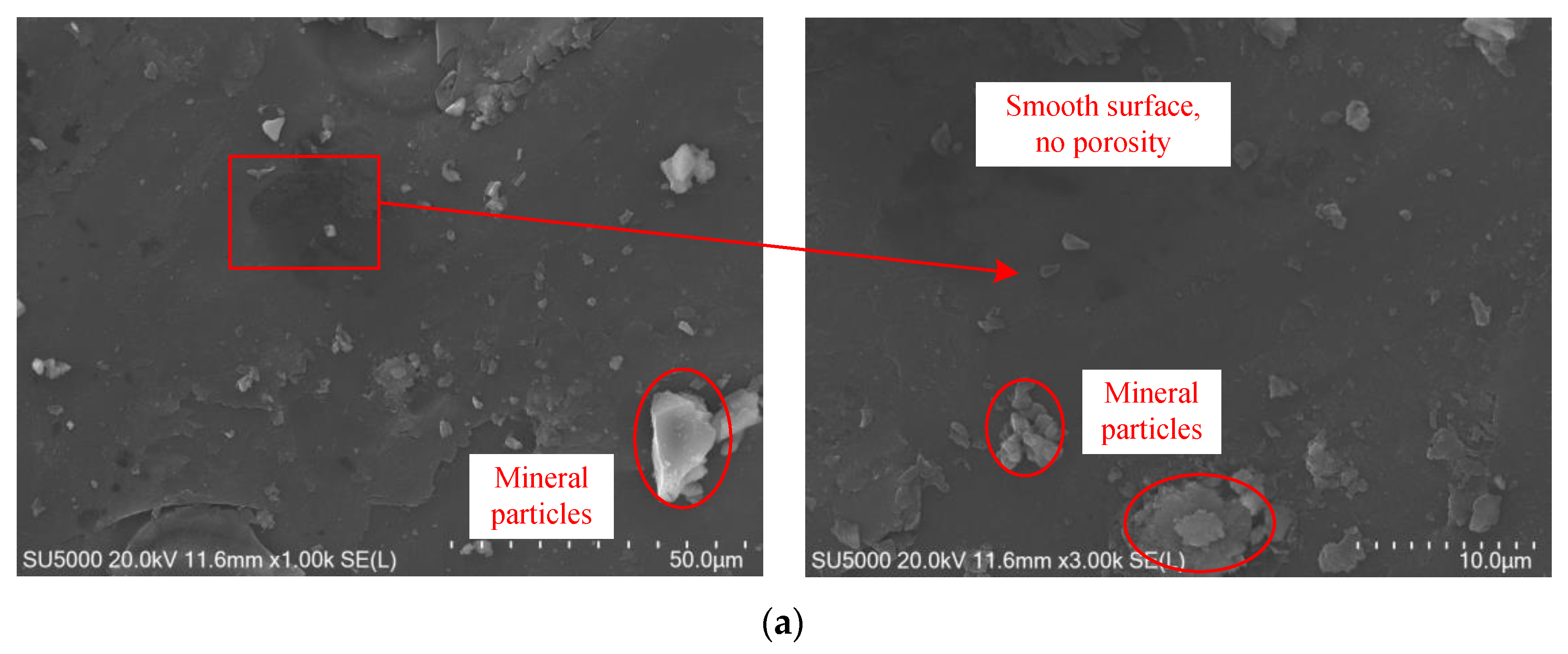
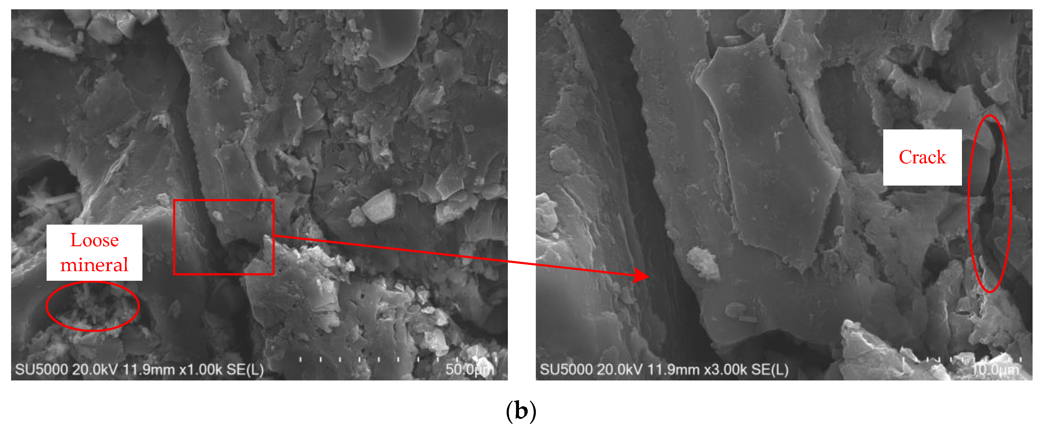
In order to explore the influence of water on the bearing capacity of the surrounding rock of the coal roadway from a microscopic perspective, a SU5000 scanning electron microscope was used to observe the microscopic morphology of natural and water-saturated coal samples. The results are shown in Figure 6. It can be seen that the mineral particles in the natural coal sample are arranged compactly, with smooth surface and few pores between particles, and the whole coal sample is neat and dense. However, in the clay mineral in the water-saturated coal sample, the originally closely connected mineral particles gradually become loose, the particles are decomposed, and the particle shape is irregular. At the same time, due to the dissolution of some minerals by water molecules, micro cracks between particles gradually develop and extend, and obvious fissures are formed in some areas, thus reducing the strength parameters of the coal body.

3.2. Macro Mechanical Characteristics

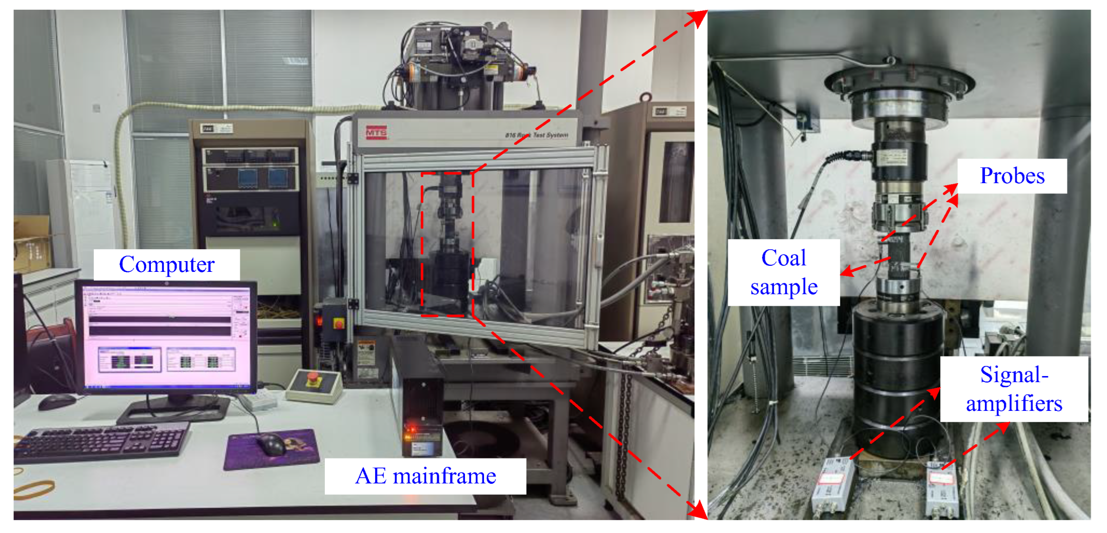
To study the influence of water on the macro mechanical characteristics of coal, the uniaxial compressive strengths of the natural and water-saturated coal samples were tested by the MTS 816 rock servo-hydraulic machine (see Figure 7), and the acoustic emission parameters were also obtained. The sample is a cylinder with a diameter of 50 mm and a height of 100 mm, and the loading rate is 0.002 mm/s [31,32]. The test results are shown in Figure 8 and Figure 9. It can be seen that the failure process of different coal samples under uniaxial compression is consistent, and all of them have gone through the compaction stage, elastic deformation stage, plastic deformation stage, and post peak failure stage. At the same time, the rate of acoustic emission counts has a good corresponding relationship with the failure process of the coal sample. The details are as follows:
(1)
In the compaction stage, the primary cracks in the coal sample are compacted and no new cracks generated, which resulting in weak acoustic emission activity and fewer acoustic emission counts;
(2)
In the elastic deformation stage, only linear elastic deformation occurs in the coal samples, and there is no new crack initiation inside. In this stage, the acoustic emission activity is also weak;
(3)
In the plastic deformation stage, the number of new cracks in the coal sample gradually increases, and the damage of the coal sample intensifies, leading to intense acoustic emission activities and a significant increase in acoustic emission counts;
(4)
At the point of peak strength, the coal sample is destroyed instantaneously and releases a large amount of energy, the intensity of acoustic emission reaches the peak, and the single ringing count exceeds 500 times;
(5)
In the post peak failure stage, the acoustic emission activity is still continuing, but the acoustic emission count decreases.
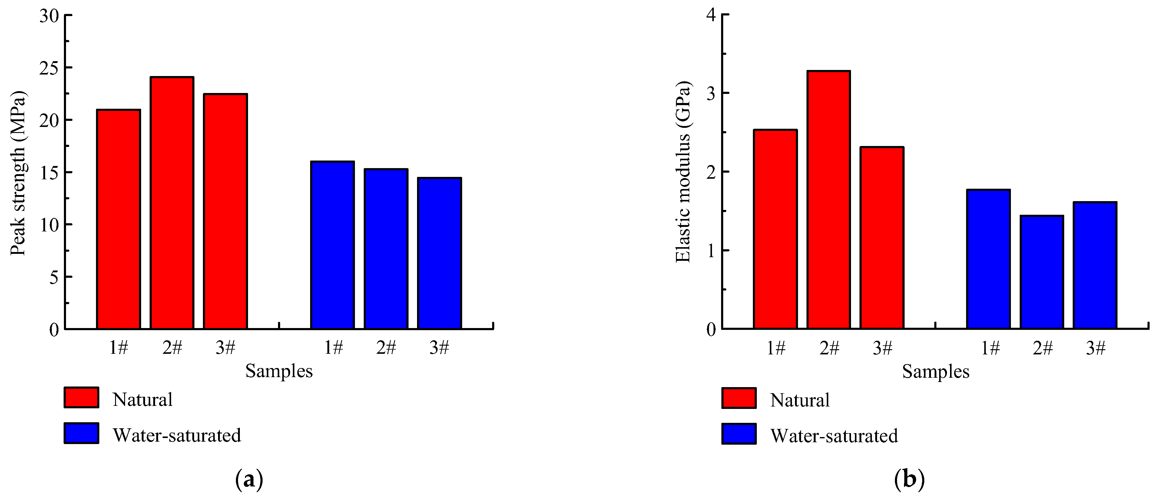
Figure 10 shows the peak strength and elastic modulus of coal samples with different states. It can be seen that the peak strength values of three natural coal samples are 20.69 MPa, 24.06 MPa, and 22.45 MPa, respectively, with an average value of 22.40 MPa. The elastic modulus values are 2.53 GPa, 3.28 GPa, and 2.31 GPa, respectively, with a average value of 2.71 GPa. However, for the water-saturated coal samples, the peak strength values are 16.01, 15.28, and 14.45, with an average value of 15.25 MPa, and the elastic modulus values are 1.77 GPa, 1.44 GPa, and 1.61 GPa, respectively, with a average value of 1.61 GPa. Both the peak strength and elastic modulus of coal samples reduced greatly after saturation, and the average peak strength and elastic modulus decreased by 31.92% and 40.59%, respectively. Therefore, the bearing capacity of surrounding rock of roadway in water-rich areas is obviously weakened, enabling a large deformation of the roadway.
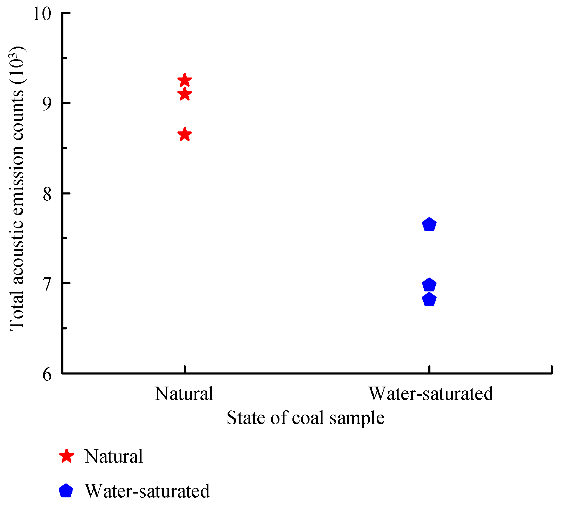
Figure 11 shows the total acoustic emission counts of coal samples with different states. It can be seen that the total acoustic emission counts of three natural coal samples are 9.25 × 10³, 8.65 × 10³, and 9.13 × 10³, respectively, with a average value of 9.01 × 10³. However, for the water-saturated coal samples, the total acoustic emission counts are 7.65 × 10³, 6.98 × 10³, and 6.82 × 10³, with a average value of 7.15 × 10³, which is 20.64% lower than the natural coal sample. This is because the water entering the coal matrix particles will destroy the bonding between particles, leading to the attenuation of the bonding force. The energy released in the failure process of coal will be reduced, the acoustic emission activity will be gentle, and the ringing count will be reduced. At the same time, it also shows that the mechanical properties of coal will be deteriorated if it is immersed in water for a long time.

3.3. In Situ Stresses

The vertical in-situ stress (σH) can be obtained by the following equation [33]:
σH = γH,
where γ is the mean volume weight of the overlying rock, 25 kN/m3; H is the overall buried depth of the 1044 return laneway, 650 m. Thus, the vertical in-situ stress is 16.25 MPa, higher than the peak strength of the water-saturated coal. This explains why the surrounding rock of 1044 return laneway in water-rich areas has large deformations after excavation.

4. New Design Structure and Parameters

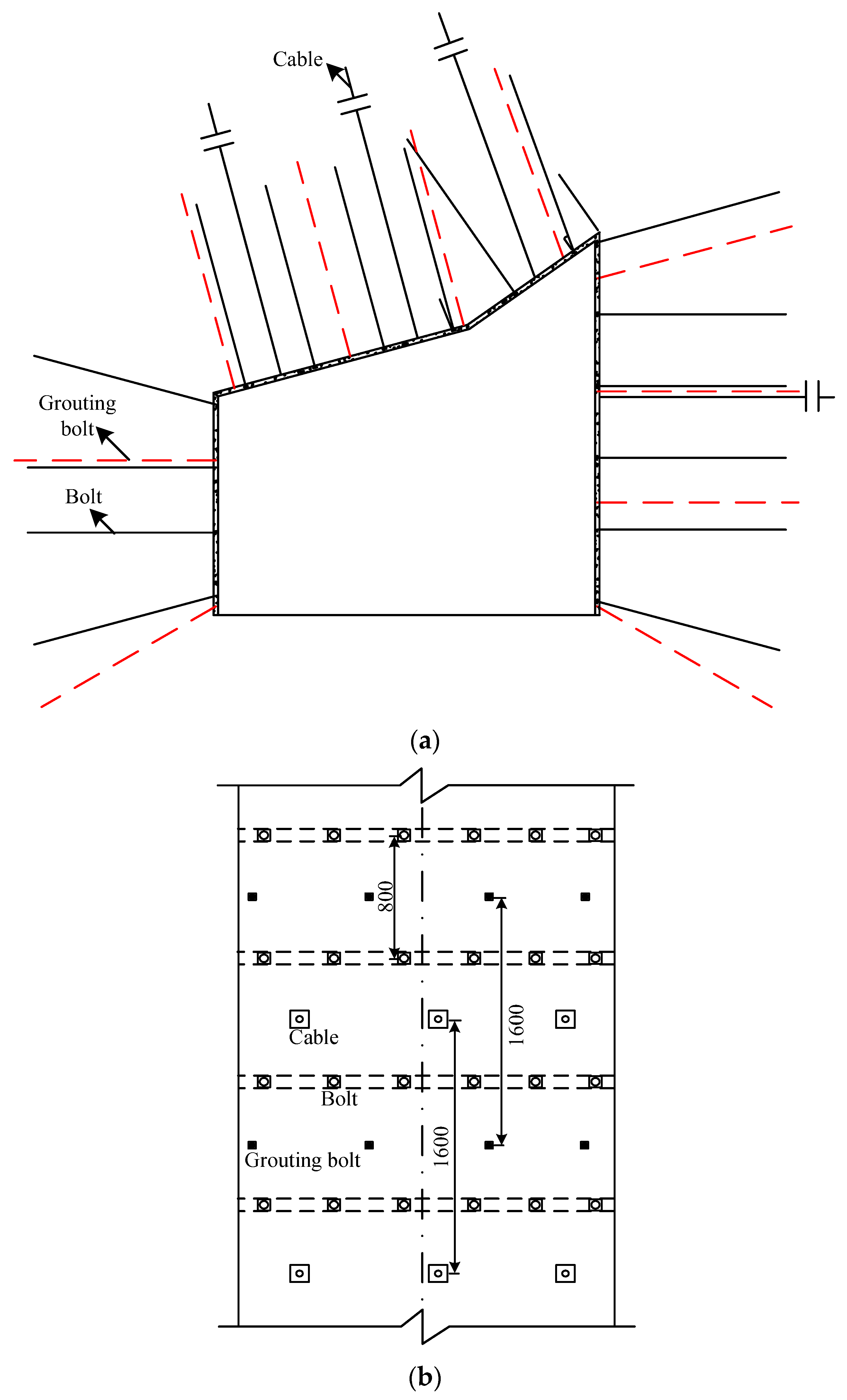
A new support design is presented in Figure 12. Bolts, cables, shotcreting with wire mesh, and grouting are all included in the new support design. The specific support steps are introduced as follows:
(1)
Firstly, bolts, cables, and wire mesh should be installed immediately after excavation to prevent the roof collapse of roadway.
(2)
Secondly, concrete is required to be sprayed onto the roadway surface to isolate air and water. In addition, the concrete solidified on the roadway surface can effectively prevent the outflow of grout and ensure the grouting quality.
(3)
Finally, grouting bolts are used to inject grout into the surrounding rock of the roadway to seal the cracks, reconstruct the fractured rock mass, improve the strength of the surrounding rock, and control the deformation of the roadway.
The specific support parameters in the new support design are listed as follows:
(1)
Bolt parameters: there are fifteen bolts with diameter of 20 mm and length of 2.4 m in the roadway cross section, including six bolts in the roof, three bolts in the left rib, and six bolts in the right rib. The spacing between the bolts in the roof and ribs along the roadway radial is 0.8~0.9 m. The row spacing of bolts of two adjacent cross sections is 0.8 m. The anchoring force of each bolt is not less than 80 kN, and all bolts should be pretensioned with a pretension load of 300 N•m. The anchorage length of each bolt must be greater than 0.6 m.
(2)
Cable parameters: there are four cables with diameter of 17.8 mm in the roadway cross section, including three cables with length of 6.3 m in the roof and one cable with length of 4 m in the right rib. The spacing between the cables in the roof along the roadway cross section is 1.6 m. The row spacing of bolts of two adjacent cross sections is 1.6 m, too. The cables are made of levorotary rebar steel with a tensile strength of 500 MPa.
(3)
Metal mesh parameters: the metal mesh with length of 2 m and width of 1 m is made of steel bar that has a diameter of 6 mm. The metal mesh is fixed on the whole roadway surface through bolt tray and nut. The grid of the metal mesh has a length/width ratio of 0.1. Two adjacent metal meshes are connected by iron wire.
(4)
Shotcreting parameters: concrete in strength grade of C20 with thickness of 100 mm is sprayed evenly to the roadway surface. The concrete composition is cement:sand:stone = 1:2:2. Enough water should be sprayed for curing in time after spraying.
(5)
Grouting bolt parameters: there are ten grouting bolts with breaking strength no less than 15 t in a roadway cross section including four in the roof, two in the left rib, and four in the right rib. The grouting bolts have a diameter of 25 mm and a length of 2.5 m. The spacing between the grouting bolts in the roof and ribs along the roadway radial is 1.2~1.6 m. The row spacing of grouting bolts of two adjacent cross sections is 1.6 m. The anchorage length of each grouting bolt must be larger than 1.5 m. Some slurry outlet holes with diameter of 6 mm are evenly distributed on the surface of each grouting bolt.
(6)
Grouting parameters: the grout is a single liquid prepared from Po42.5 ordinary silicate cement with a water/cement ratio of 1:1. The final grouting pressure is 2∼3 MPa [34,35]. The grouting is implemented within 15∼18 days after the excavation of 1044 return laneway.
Compared to the original support, the new support can bond the support with the surrounding rock of the roadway and fully utilize the self-supporting capability of the surrounding rock.

5. On-Site Monitoring

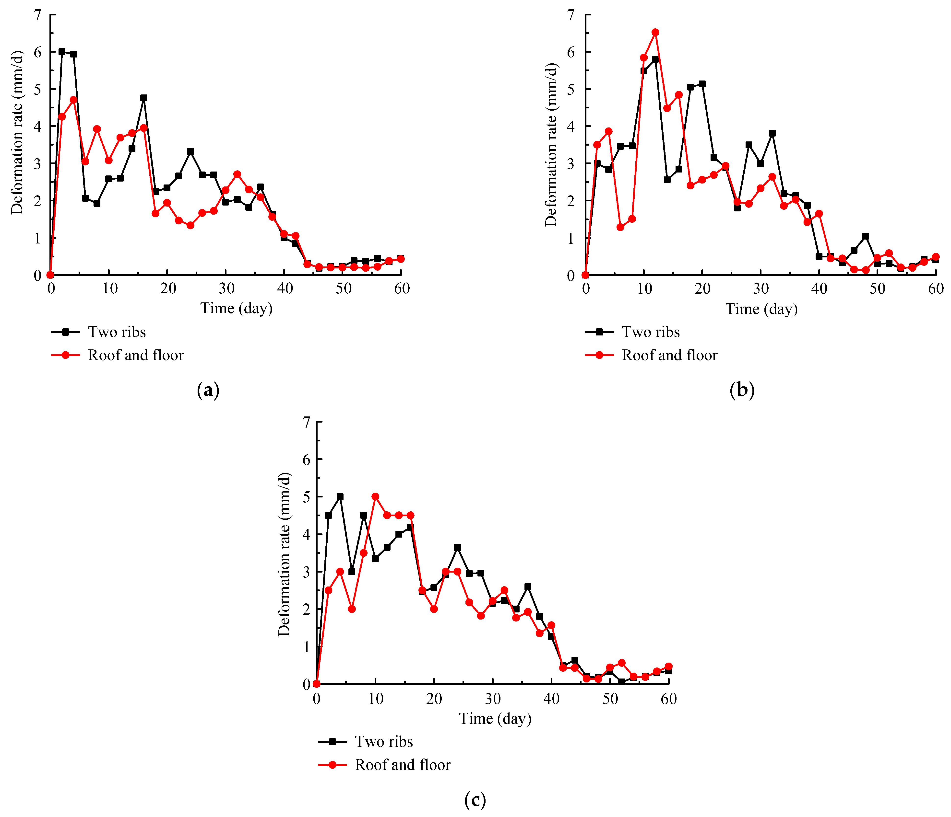
Field industrial experiments and monitoring were performed in the 1044 return laneway to test the quality of the new support design. The monitoring results of cumulative deformation and deformation rate in the 1044 return laneway are shown in Figure 13 and Figure 14, respectively. It can be seen that the deformations increase obviously with a deformation rate of 2~6.5 mm/d during the first 35 days after supporting the roadway. However, the deformations tend to be stable with a deformation rate less than 0.5 mm/d after approximately 40 to 60 days; the final deformations of roof and floor are about 108~120 mm, and the shrinkages of two ribs are about 117~135 mm, which are significantly smaller than the data with the original support in Figure 4 and Figure 5.
In general, compared with the original support, the new support can reduce the deformation of the 1044 return laneway by nearly 90%. During the monitoring period, the roadway roof, ribs, and floor with the new support design were intact and no obvious failure was visible. In contrast, the roadway with the original support experienced large deformations and severe failure. Data from field monitoring indicate that the new support design can effectively control the deformation and maintain long term stability of the 1044 return laneway.

6. Conclusions

A case study of the failure mechanisms and support technology for a water-rich coal roadway in the Taoyuan Coal Mine was carried out through laboratory experiment, field test, and theoretical analysis. The main conclusions can be summarized as follows:
(1)
SEM scanning results show that due to the dissolution of some minerals by water molecules, micro cracks between particles gradually develop and extend, and obvious fissures are formed in the water-saturated coal sample. Macro mechanical test results show that the strength of water-saturated coal decreases significantly compared with natural coal. Therefore, the surrounding rock of 1044 return laneway in a water-rich area experiences large deformations under high vertical in-situ stress.
(2)
Based on the failure mechanism, a new optimal support design was proposed, which included bolt, cable, metal mesh, shotcrete, and grouting. Furthermore, the construction sequence and detailed support parameters were also introduced.
(3)
A field test with the new support design was performed in 1044 return laneway. Results show that the new support can reduce the deformation by at least 90% compared with the original support. With the new support technology, the long-term stability of the roadway in a water-rich area can be effectively ensured, which provides a significant reference for the support design of roadway with similar geologic conditions.

Author Contributions

Conceptualization, H.F. and X.N.; methodology, H.F.; validation, X.N.; formal analysis, S.L.; investigation, X.N.; resources, X.N.; data curation, H.F.; writing—original draft preparation, H.F.; writing—review and editing, S.L.; supervision, S.L.; funding acquisition, H.F. All authors have read and agreed to the published version of the manuscript.

Funding

This research was funded by the Natural Science Foundation of Anhui Province (Grant No. KJ2021A0457), Major Special Projects of Science and Technology of Anhui Province (Grant No. 202203a07020010), Opening Foundation of the State Key Laboratory of Mining Response and Disaster Prevention and Control in Deep Coal Mines (Grant No. SKLMRDPC21KF09), and Scientific Research Foundation for High-level Talents of Anhui University of Science and Technology (Grant No. 2021yjrc15).

Institutional Review Board Statement

Not applicable.

Informed Consent Statement

Not applicable.

Data Availability Statement

The data used for conducting classifications are available from the corresponding author upon request.

Acknowledgments

The authors would like to thank the workers in Taoyuan Coal Mine for their field data.

Conflicts of Interest

The authors declare no conflict of interest.

References

  1. Guo, H.J.; Tang, H.L.; Wu, Y.C.; Wang, K.; Xu, C. Gas seepage in underground coal seams: Application of the equivalent scale of coal matrix-fracture structures in coal permeability measurements. Fuel 2021, 288, 119641. [Google Scholar] [CrossRef]
  2. Fu, Q.; Yang, K.; He, X.; Wei, Z.; Yang, Q. Characteristics of Strata Behavior and Differentiated Control of Fully Mechanized MiningWorking Face with Abnormal Roof. Sustainability 2022, 14, 13354. [Google Scholar] [CrossRef]
  3. Luo, Y.; Gong, F.Q.; Zhu, C.Q. Experimental investigation on stress-induced failure in D-shaped hard rock tunnel under water-bearing and true triaxial compression conditions. Bull. Eng. Geol. Environ. 2022, 81, 76. [Google Scholar] [CrossRef]
  4. Hadizadeh, J.; Law, R.D. Water-weakening of sandstone and quartzite deformed at various stress and strain rates. Int. Rock Mech. Min. Sci. Geomech. 1991, 28, 431–439. [Google Scholar] [CrossRef]
  5. Nam, S.W.; Bobet, A. Radial deformations induced by groundwater flow on deep circular tunnels. Rock Mech. Rock Eng. 2007, 40, 23–39. [Google Scholar] [CrossRef]
  6. Fan, H.; Wang, L.; Wang, S.; Jiang, C. A new unified solution for deep tunnel in water-rich area considering pore water pressure. Geofluids 2021, 2021, 6696757. [Google Scholar] [CrossRef]
  7. Shin, Y.J.; Kim, B.M.; Shin, J.H.; Lee, I.M. The ground reaction curve of underwater tunnels considering seepage forces. Tunn. Undergr. Space Technol. 2010, 25, 315–324. [Google Scholar] [CrossRef]
  8. Wang, H.T.; Wang, L.G.; Li, S.C.; Wang, Q.; Liu, P.; Li, X.J. Roof collapse mechanisms for a shallow tunnel in two-layer rock strata incorporating the influence of groundwater. Eng. Fail. Anal. 2019, 98, 215–227. [Google Scholar] [CrossRef]
  9. Zhang, J.; Wang, Y.; Qi, X.; Zhu, T. Research on application of the bolt-truss coupling support technology in roadway with water-rich and soft rock. Front. Earth Sci. 2022, 10, 842672. [Google Scholar] [CrossRef]
  10. Tian, Y.; Wang, Q.; Hu, Z.; Yang, S.; Peng, C.; Zhang, X.; Li, Z.; Wang, X. Research on the influence of groundwater in coastal areas on the stress and deformation characteristics of integrated pipe gallery. Geofluids 2022, 2022, 3463752. [Google Scholar] [CrossRef]
  11. Bhattacharya, P.; Dutta, P. Stability of rectangular tunnel in Hoek–Brown rocks under steady-state groundwater flow. Geotech. Lett. 2020, 10, 524–534. [Google Scholar] [CrossRef]
  12. Wang, Y.C.; Liu, Y.; Li, Y.L.; Jiang, W.; Wang, Y. Experimental study on the failure mechanism of tunnel surrounding rock under different groundwater seepage paths. Geofluids 2021, 2021, 8856365. [Google Scholar] [CrossRef]
  13. Shi, C.; Cao, C.; Lei, M.; Yang, W. Face stability analysis of shallow underwater tunnels in fractured zones. Arab. J. Geosci. 2016, 9, 24. [Google Scholar] [CrossRef]
  14. Pan, J.; Guo, Q.; Ren, F.; Cai, M. Comparative analysis of different strength criteria for deep-buried rock roadway under seepage. J. China Coal Soc. 2019, 44, 3369–3378. [Google Scholar]
  15. Qin, C.; Chian, S.C.; Yang, X.; Du, D. 2D and 3D limit analysis of progressive collapse mechanism for deep-buried tunnels under the condition of varying water table. Int. J. Rock Mech. Min. Sci. 2015, 80, 255–264. [Google Scholar] [CrossRef]
  16. Hao, M.; Pan, X.; Zhang, B. Deformation failure characteristics and support technology of weakly cemented soft rock roadway under water spraying condition. Safe. Coal Mines 2021, 52, 219–228. [Google Scholar]
  17. Zhai, W.; He, F.; Xu, X.; Lv, K.; Li, L.; Song, J. Floor heave mechanism in water-rich soft rock roadways and a DS-IBA control approach. Geomat. Nat. Haz. Risk 2022, 13, 2107–2123. [Google Scholar] [CrossRef]
  18. Lu, H.; Yin, J.; Liu, Q.; Cao, A.; Wei, A.; Zhang, K. A self-dissolved grouting reinforcement method for water-rich soft rock roadway. Bull. Eng. Geol. Environ. 2022, 81, 256. [Google Scholar] [CrossRef]
  19. Lin, W.; Cheng, J.; Li, D.; Dang, H. Deformation characteristics and control technology of roadway in water-rich soft rock. Geofluids 2022, 2022, 2234334. [Google Scholar] [CrossRef]
  20. Cheng, J.; Wei, Z.; Bai, J.; Yu, Z.; Xing, K.; Li, Q.; Wang, J.; Li, X.; Zhang, C.; Zhang, Z. Study on floor heave control technology of deep tectonic stress water-rich soft rock roadway based on blasting pressure relief. Coal Sci. Technol. 2022, 50, 117–126. [Google Scholar]
  21. Jiang, B.; Wang, L.; Lu, Y.; Gu, S.; Sun, X. Failure mechanism analysis and support design for deep composite soft rock roadway: A case study of the Yangcheng coal mine in China. Shock Vib. 2015, 2015, 452479. [Google Scholar] [CrossRef] [Green Version]
  22. Lu, Y.L.; Wang, L.G.; Zhang, B. An experimental study of a yielding support for roadways constructed in deep broken soft rock under high stress. Min. Sci. Technol. 2011, 21, 839–844. [Google Scholar] [CrossRef]
  23. Wang, K.; Wang, L.; Ren, B. Failure Mechanism Analysis and Support Technology for Roadway Tunnel in Fault Fracture Zone: A Case Study. Energies 2021, 14, 3767. [Google Scholar] [CrossRef]
  24. Ma, Z.; Jiang, Y.; Du, W.; Zuo, Y.; Kong, D. Fracture evolution law and control technology of roadways with extra thick soft roof. Eng. Fail. Anal. 2018, 84, 331–345. [Google Scholar] [CrossRef]
  25. Kang, H.P.; Jiang, P.F.; Huang, B.X.; Guan, X.M.; Wang, Z.G.; Wu, Y.Z.; Gao, F.Q.; Yang, J.W.; Cheng, L.X.; Zheng, Y.F.; et al. Roadway strata control technology by means of bolting-modification-destressing in synergy in 1000 m deep coal mines. J. Chin. Coal Soc. 2020, 45, 845–864. [Google Scholar]
  26. Wang, L.G.; Lu, Y.L.; Huang, Y.G.; Sun, H.Y. Deep-shallow coupled bolt-grouting support technology for soft rock roadway in deep mine. J. Chin. Univ. Min. Technol. 2016, 45, 11–18. [Google Scholar]
  27. Wang, F.; Zhang, C.; Wei, S.; Zhang, X.; Guo, S. Whole section anchor-grouting reinforcement technology and its application in underground roadways with loose and fractured surrounding rock. Tunn. Undergr. Space Technol. 2016, 51, 133–143. [Google Scholar]
  28. Wang, Q.; Pan, R.; Jiang, B.; Li, S.; He, M.; Sun, H.; Wang, L.; Qin, Q.; Yu, H.; Luan, Y. Study on failure mechanism of roadway with soft rock in deep coal mine and confined concrete support system. Eng. Fail. Anal. 2017, 81, 155–177. [Google Scholar] [CrossRef]
  29. Wang, Q.; Jiang, B.; Li, S.C.; Wang, D.C.; Wang, F.Q.; Li, W.T. Experimental Studies on the Mechanical Properties and Deformation & Failure Mechanism of U-type Confined Concrete Arch Centering. Tunn. Undergr. Space Technol. 2016, 51, 20–29. [Google Scholar]
  30. Kai, Z.; Zhang, G.; Hou, R.; Wu, Y.; Zhou, H. Stress evolution in roadway rock bolts during mining in a fully mechanized longwall face, and an evaluation of rock bolt support design. Rock Mech. Rock Eng. 2015, 48, 333–344. [Google Scholar]
  31. Li, Z.; Li, J.; Li, H. Effect of concave terrain on explosion-induced ground motion. Int. J. Rock Mech. Min. Sci. 2021, 148, 104948. [Google Scholar] [CrossRef]
  32. Li, J.; Yuan, W.; Li, H.; Zou, C. Study on dynamic shear deformation behaviors and test methodology of sawtooth-shaped rock joints under impact load. Int. J. Rock Mech. Min. Sci. 2022, 158, 105210. [Google Scholar] [CrossRef]
  33. Li, S.B.; Wang, L.; Ren, Q.H.; Zhu, C.Q.; Liu, H.Q.; Liu, H.Q.; Chen, L.P. A study on the influence of mining depth on the stress distribution characteristics of stope surrounding rock. Geofluids 2022, 2022, 4178554. [Google Scholar] [CrossRef]
  34. Li, Z.L.; Wang, L.G.; Ding, K. Effect of Strong Mining on the Fracture Evolution Law of Trick Rise in the Mining Field and Its Control Technology. Geofluids 2022, 2022, 3953650. [Google Scholar] [CrossRef]
  35. Zhang, J.; Liu, L.; Liu, C.; Sun, D.; Shao, J. Application of bolt-grouting reinforcement for broken surrounding rock based on prestressed bolt and self-stress grouting. J. Min. Safe. Eng. 2021, 38, 774–783. [Google Scholar]
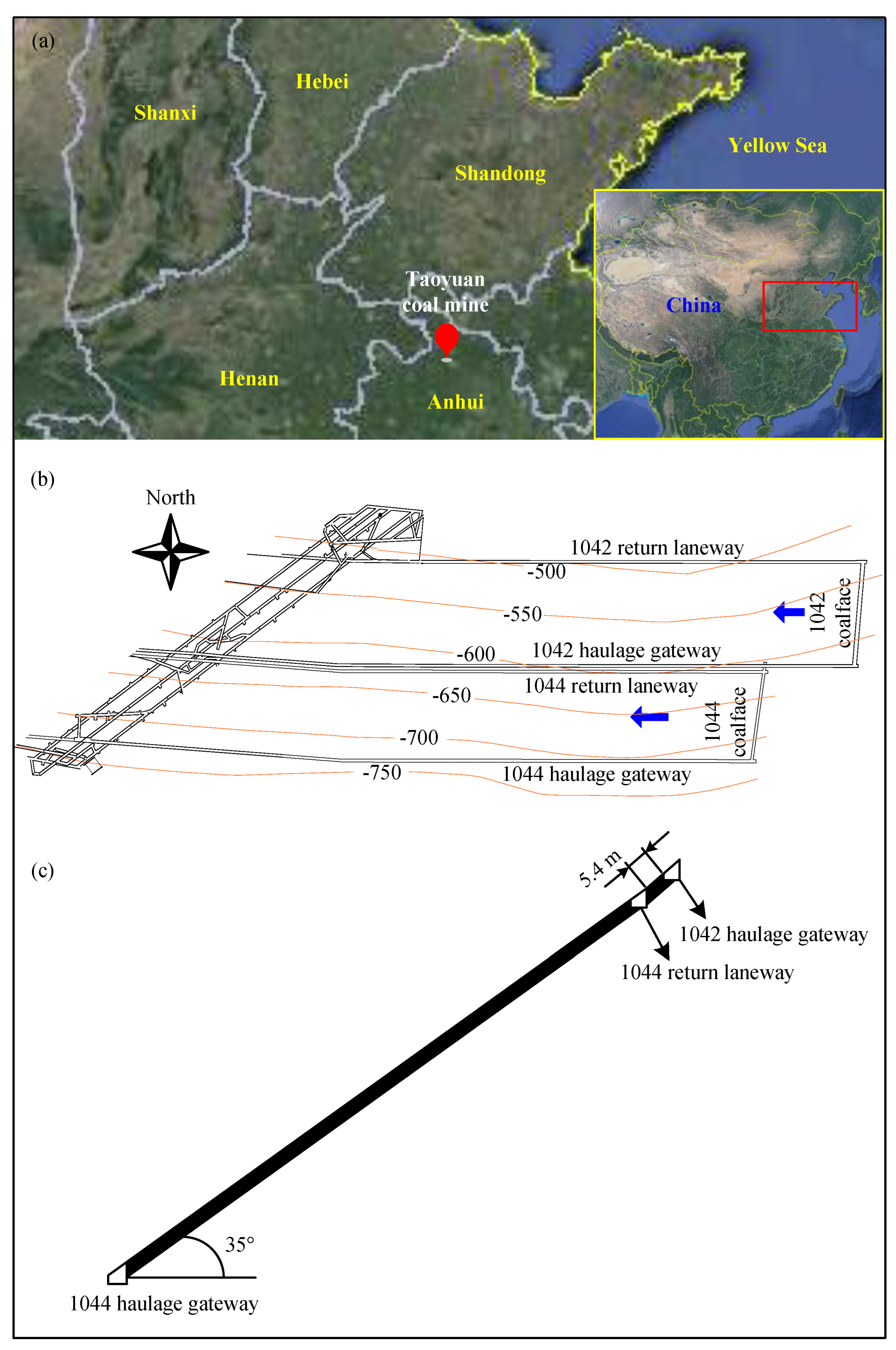
Figure 1. Location of the 1044 coalface. (a) Location of Taoyuan Coal Mine; (b) Location of 1044 coalface; (c) Coalface section.
Sustainability 15 00410 g001
Figure 2. Strata histogram of the 10# coal seam.
Sustainability 15 00410 g002
Figure 3. Initial support design of the 1044 return laneway.
Sustainability 15 00410 g003
Figure 4. Cumulative deformation of the 1044 return laneway with the original support. (a) Station 1; (b) Station 2; (c) Station 3.
Sustainability 15 00410 g004
Figure 5. Deformation rate of the 1044 return laneway with the original support. (a) Station 1; (b) Station 2; (c) Station 3.
Sustainability 15 00410 g005aSustainability 15 00410 g005b
Figure 6. Microscopic morphology of coal sample with different states. (a) Natural coal sample; (b) Water-saturated coal sample.
Sustainability 15 00410 g006aSustainability 15 00410 g006b
Figure 7. MTS 816 rock servo-hydraulic machine.
Sustainability 15 00410 g007
Figure 8. Stress-strain curve of natural coal samples. (a) Sample 1; (b) Sample 2; (c) Sample 3.
Sustainability 15 00410 g008
Figure 9. Stress-strain curve of water-saturated coal samples. (a) Sample 1; (b) Sample 2; (c) Sample 3.
Sustainability 15 00410 g009
Figure 10. Peak strength and elastic modulus of coal samples with different states. (a) Peak strength; (b) Elastic modulus.
Sustainability 15 00410 g010
Figure 11. Total acoustic emission counts of coal samples with different states.
Sustainability 15 00410 g011
Figure 12. New support design of 1044 return laneway. (a) Sectional view; (b) Top view.
Sustainability 15 00410 g012
Figure 13. Cumulative deformation of the 1044 return laneway with the new support. (a) Station 1; (b) Station 2; (c) Station 3.
Sustainability 15 00410 g013
Figure 14. Deformation rate of the 1044 return laneway with the new support. (a) Station 1; (b) Station 2; (c) Station 3.
Sustainability 15 00410 g014
Disclaimer/Publisher’s Note: The statements, opinions and data contained in all publications are solely those of the individual author(s) and contributor(s) and not of MDPI and/or the editor(s). MDPI and/or the editor(s) disclaim responsibility for any injury to people or property resulting from any ideas, methods, instructions or products referred to in the content.