1. Introduction
Nowadays, the world is moving toward clean and renewable energy production as a replacement for the energy production from traditional, fossil fuel-based sources. Due to significant environmental impact, increases in fossil fuel prices, and a rise in sustainable energy sources, the energy industry has invested and explored other eco-friendly replacements [
1,
2,
3,
4]. Currently, solar energy remains one of the most promising renewable energy sources, due to the fact that it is an infinite, accessible, and eco-friendly source of sustained energy [
2,
5,
6,
7]. The Kingdom of Saudi Arabia (KSA) has a vision for a clear, eco-friendly future that aims to be achieved by 2030, when 50% of its energy needs would be supplied by renewable energy sources [
8]. Additionally, among these renewable energy sources, the KSA aims to achieve a photovoltaic (PV) production of 1481 MW by 2022, which corresponds to about 6.71% of its yearly energy needs [
4]. In addition, KSA has made its first green city, NEOM, where only renewable energy sources are utilized to power the whole town. Another important use of solar energy, other than power production, is direct solar heating, which can be used in many solar applications, such as air and water heating.
Shape memory alloy (SMA) is a type of smart material that has unique thermomechanical properties, which result in a special behavior called the ‘shape memory effect’ (SME) [
9,
10,
11,
12]. The SME effect allows the SMA to reattain a predefined shape when the alloys undergo specific thermomechanical processes that provide use for SMA [
10,
13]. There are two main phases for SMAs, Martensite and Austinite. Martensite is the phase in which the shape memory alloy has a low temperature along with a low yield strength, while Austenite is the phase in which the temperature is raised, and a higher yield strength is achieved in order for the material to regain its original shape during preheating. The activation temperature of the SMA spring primarily depends on the material composition and physical properties. Manufacturers, such as Dynalloy company, can design and customize it to achieve a wide range of activation temperatures [
6]. SMAs are used in many applications, such as medicine, biomedicine, and robotics, as well as aerospace, mechanical, and civil engineering [
9,
13,
14,
15,
16,
17,
18]. There are many types of SMAs, depending on the chemical compound of the material. Although some of these materials are iron-based (such as Fe-Mn-Si and Fe-Mn-Ni-Al), some others are copper-based (such as Cu-Zn and Cu-Al) [
10,
15,
17]. The most popular type of SMA is the Nickel -Titanium-based alloy (also known as NiTiNOL or Ni-Ti), because it has a low cost, a high reversibility of SME, and good thermomechanical properties, such as good durability for corrosion, fatigue, and aging, a low operating temperature, and a high force density [
15,
17,
19].
Many researchers have a great interest in exploring the different characteristics of NiTiNOL, due to its operating temperature, large strain, and actuating force to facilitate a variety of applications [
19,
20,
21,
22,
23,
24,
25,
26,
27]. For instance, Catoor, et al. [
25] studied the relationship between certain electrical conditions, displacement, temperature, resistance, and response speed. The results showed that as the current increases, the displacement and response speed change accordingly, due to the change in temperature. These studies have enabled the development of new actuation mechanisms. Hu, et al. [
28] intensively investigated the literature regarding the thermomechanical behavior of SMAs, such as critical stresses, Austenite phase, and Martensite phase. Such studies help to understand SMAs better and therefore lead to further developments and implementations of SMAs.
Mohd Jani, et al. [
29] stated that SMA-driven actuators with SMA-actuation mechanisms generally fall under two main types: linear and rotary motions. In both types, the main factors considered while designing an actuator are force, displacement, stroke, size, durability, and frequency. These factors determine the design specifications, such as material, loading configuration shape, cooling, heating method, design type, design approach, and control mechanism. As a result of such studies, the development of advanced SMA-based actuators has accelerated; innovative mechanisms have made a considerable leap in research and development and show a bright future [
13,
18,
26,
30,
31]. As proof, multiple reviews have been carried out for investigating different types of SMA-based actuators and comparing the actuators [
10,
13,
15,
28,
29,
32]. For instance, Doroudchi et al. [
18] developed an antagonistic configured rotary actuator in order to achieve a high frequency, and the proposed system reached a frequency of 5 Hz for a 4° peak-to-peak rotation. In comparison, a 1° peak-to-peak rotation was reached for a frequency of 10 Hz.
Solar energy is one of the most promising renewable energy sources, as mentioned previously, since it is profusely available, cheap, and noiseless [
33,
34,
35]. Solar energy can be divided into three types: photovoltaic, thermal, and photovoltaic/thermal [
36]. One of the most popular forms of solar thermal energy is the energy produced by solar heat collectors (SHCs). The conversion of solar energy to thermal energy is much more efficient and more accessible than the conversion to electrical energy. The conversion to thermal energy efficiency is about 70%, while the conversion to electrical energy is about 17% [
37,
38]. In addition, many researchers have discussed different methods and technology to improve and assess the performance of SHCs [
34]. The performance of SHC is affected by many factors, such as the structure of the SHC, working fluid, and storage methodology [
34,
39]. SHC is a uniquely shaped heat exchanger that extracts thermal energy from solar irradiation by absorbing heat and then storing it in a fluid to utilize it in its form or in another form [
36,
39]. SHCs can be used in many applications, such as power generation, space and water heating, and desalination systems [
39]. SHCs can be divided into different types based on multiple categories, for example, the way they are driven, their shape, or the fluid used inside them [
36,
40].
The primary way to activate the SME is via heating the alloy, and one proposed method in this study is to obtain the required heat is by using an SHC. SHCs have a considerable advantage over other heating methods since they do not require electricity to operate, are accessible, and are easy to operate and use [
37,
40]. There are many types of material used for SHCs, and each type has its own unique application. For instance, aluminum and copper are known to be used as absorbers [
34,
36,
41], while different fluids, such as air, water, and nanofluids, are used to absorb the heat collected via the SHC [
34,
41,
42,
43,
44,
45].
The integrations of SMAs with solar thermal applications enable the development of advanced technology solutions, such as solar-based overheating protection systems, as well as self-cleaning and self-tracking systems. The overheating protection system is an important aspect that should be considered in some solar thermal applications; for example, Hussain and Harrison [
46] studied numerically and experimentally the effect of the natural cooling of an Flat Plate Collector (FPC) in order to monitor the overheating of the FPC. The authors built a three-dimensional, finite-volume, simulation-based, model-validated versus experiment that has been carried out in a residential FPC under stagnation conditions. The results revealed that the integrated FPC, along with the designed air-cooling channel and control valve, can provide smooth, suitable heat transfer rates and retain the maximum temperature of the FPC absorber. Similarly, Kessentini, et al. [
47] investigated the effect of the overheating protection system and transparent insulation material on an FPC. The overheating protection system uses a ventilation channel door that can be thermally actuated using SMA springs. The proposed technique was found to allow the FPC to operate at the desired absorber temperature and give good efficiency. Another SMA-based technology has been proposed by Hariri [
6] to compensate for the dust accumulation dilemma that occurs in PV modules. The innovative technology that has been designed for dust mitigation of PV modules considers using an SMA wires actuator that is activated via the wasted heat generated by the PV modules. The results ensure the effectiveness of the proposed system in an indoor experiment using a sun simulator. Another study made by Riad et al. [
30] proposed a NiTiNOL-based actuated solar tracking system (STS). The NiTiNOL-based STS uses heat energy absorbed via the sun as a natural heat source for the NiTiNOL springs to enable the STS to change its orientation. The proposed system increased the energy yield of the PV module by 39% in comparison to a fixed-tilt PV module.
In order to design a solar collector, there are three main aspects to be considered: the technical specifications, the cost-effectiveness, and the environmental impact [
48]. Technical specifications are important to ensure the feasibility of thermal energy constructed by the solar collector. The cost-effectiveness is always directly linked to the technical specifications, which allows the designer to know the payback period of the investment. Additionally, the degree of environmental impact ensures environmental regulation and standards [
49].
This paper aims to present a novel design for a piston-based thermomechanical actuator, as well as carry out a thermal simulation-based study for the proposed design. The numerical thermal study investigates and analyzes the temperature profile inside the thermomechanical actuator throughout the year with the natural weather conditions of Dammam city, KSA. Furthermore, the thermomechanical actuator is intended to be a passive type, since it uses the solar energy as a thermal energy input to the actuator via a simple heat collector design, as a part of the proposed actuator. In addition, it is self-operating, since it uses the natural solar heat to be activated and deactivated in day and night periods. The SHC uses the air as the fluid inside the heat collector. The proposed system utilizes the thermomechanical behavior in the SMA. It offers a green solar actuator that can be used autonomously in many solar applications without any electrical supply or human interaction. Therefore, this study presents the promising developments of innovative actuation mechanisms for sustainable technology solutions in various solar applications. Moreover, this paper provides great insight into many research avenues and projects regarding solar-driven thermomechanical actuators and their potential real-life applications within various fields. One of the main advantages of the developed solar-based thermomechanical actuator is the development of solar-based self-cleaning or tracking systems for PV modules, in addition to many real-life applications in the field of renewable energy.
2. Materials and Methods
This study is carried out to design and simulate the thermal behavior of a passive smart thermomechanical actuator. The basic conceptional idea of the proposed state-of-the-art passive smart thermomechanical actuator is represented in
Figure 1, in which an SHC containing two sets of springs is shown. These spring arrangements with the movable rod ensure the linear dynamics of the piston-like SMA-based system. On the other hand, NiTiNOL SMA springs and normal-tension bias springs are the two sets that are shown inside the SHC, as seen below. Each set would be connected to one end of the heat collector and the movable piston. Therefore, the SMA springs enable the actuator to produce force when it is heated and activated due to the sunrise, and after that, return back to its original status during the night when it is cooled, and thereby completing one cycle, as seen in
Figure 2.
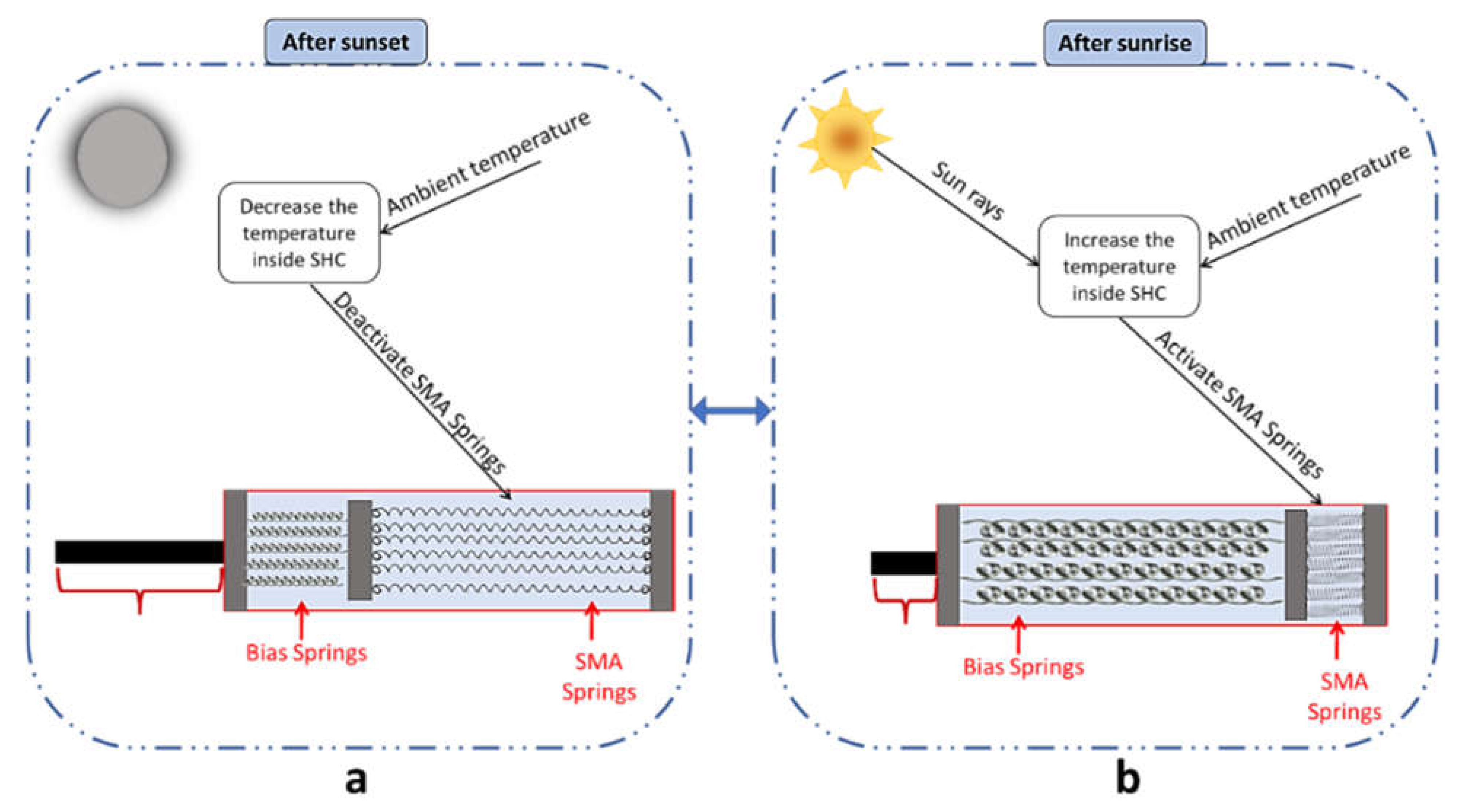
Consequently, the proposed actuator aims to be activated and deactivated once a day. During the evening period, the SMA arrangement would be deactivated, as shown in
Figure 2a, while maintaining the temperature inside and with the SHC less than the activation temperature of the SMA springs. On the other hand, the SMA springs would be activated after sunrise and during the day, taking the thermal energy from the sun’s rays and the ambient temperature, as illustrated in
Figure 2b. When the actuator is activated (once activation temperature is reached), the SMA springs contract to their original shape while the bias springs stretch. In contrast, when the actuator is deactivated (once below the activation temperature), the SMA spring stretches back to the position given by the bias spring, while the bias springs contract.
The design of the SHC remains the crucial element and the challenging component for the successful development of the proposed passive thermomechanical SMA actuator presented in this work. Since the smart solar-driven actuator is entirely dependent on the temperature variation throughout the day for the activation and de-activation processes, the temperature inside the SHC must be optimized for activating the SMA springs after sunrise and suitable for deactivating the SMA springs after sunset. Additionally, the temperature distribution inside the SHC must be consistent because it highly affects the temperature of the different SMA springs. Moreover, the temperature variation inside the SHC must be considered on different days, since the year’s seasons significantly affect the sun rays and ambient temperature.
2.1. Workflow
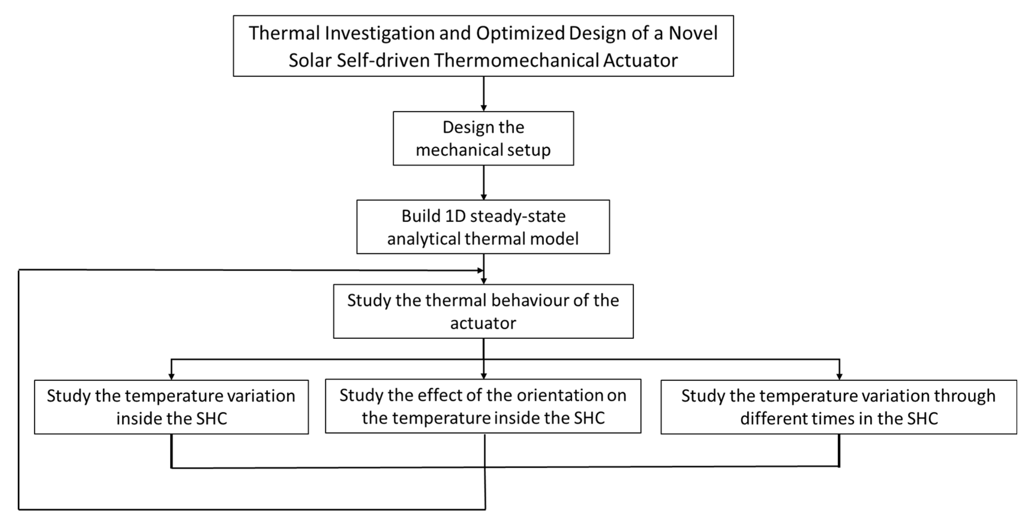
The principal methodology that has been followed to design the novel solar self-driven thermomechanical actuator is shown in
Figure 3. Firstly, the mechanical design of the thermomechanical actuator has been made via a computer-aided design (CAD) software, where all the thermomechanical parts have been assembled in order to ensure the functionality of each part (as highlighted in the following
Section 2.2). After that, a simplified one-dimensional (1D) numerical steady-state thermal model was achieved for the thermomechanical actuator.
After that, a computational fluid dynamics (CFD) model of the thermomechanical actuator was carried out. Different analyses have been carried out to study the thermal behavior of the proposed solar-driven thermomechanical actuator as follows: a thermal study of the temperature variation inside the body of the thermomechanical actuator, a thermal study of the effect of the orientation of the thermomechanical actuator on the temperature distribution, and a thermal study of the temperature variation throughout a full year of 365 days within 2022.
This thermal investigation has been carried out to validate the tremendous potential, possibility, and functionality of the designed thermomechanical actuator to operate throughout the year in the studied region, and therefore provide an innovative technology solution to drive many solar-related applications, such as the self-cleaning of PV modules and self-tracking of solar applications.
2.2. Actuator Mechanical Design
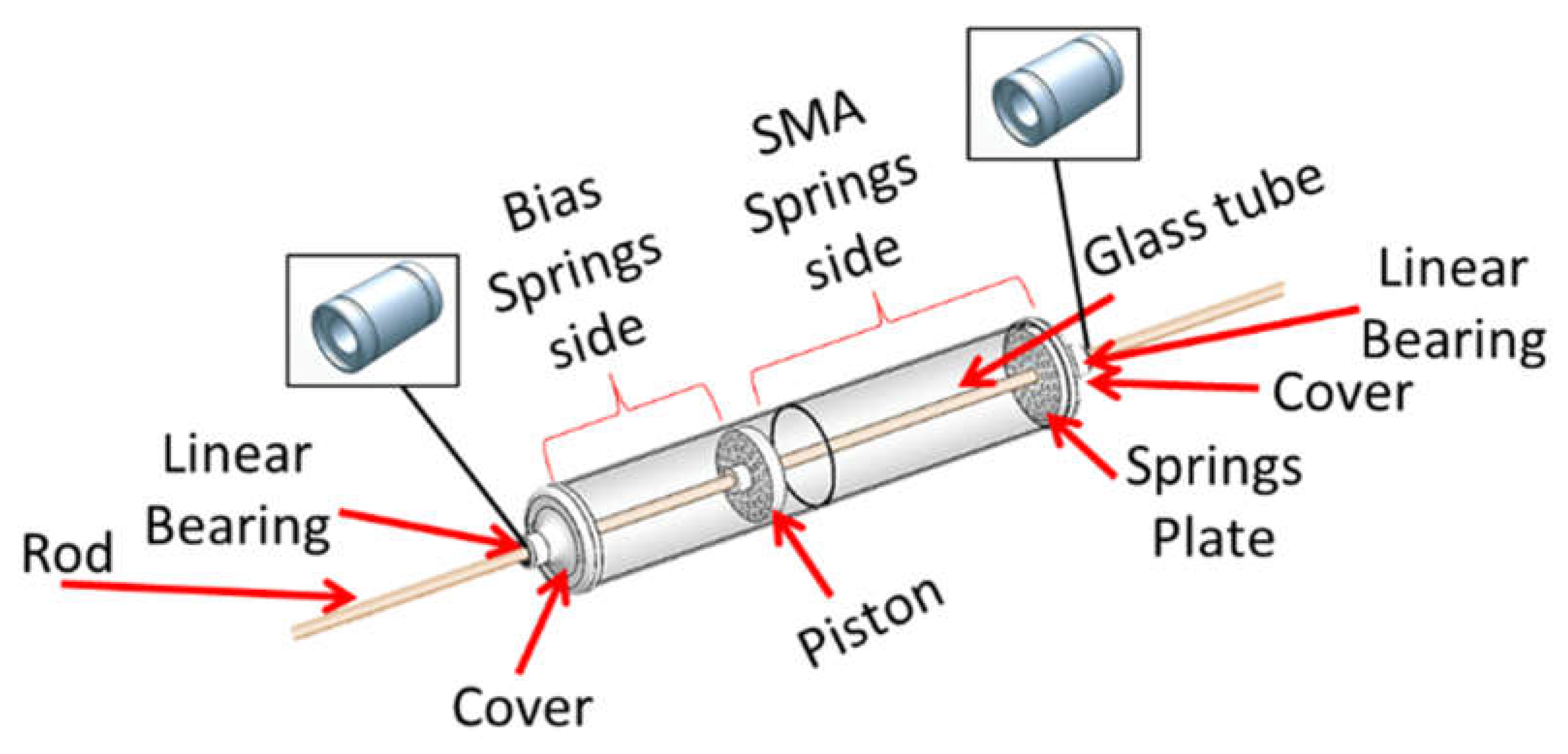
The developed CAD model of the thermomechanical actuator aims to be compact, portable, easy to install, and manufactured with a high thermal efficiency. The thermomechanical SMA actuator consists of five main parts: a heat collector, a piston, a rod, bias springs, and NiTiNOL springs, as shown in
Figure 4. The aim of using a heat collector, in the form of a cylindrical tube (36 cm length × 6 cm diameter), is to collect the thermal energy needed to activate the NiTiNOL springs, which can be considered the core element of this actuator. Furthermore, the movable piston connects the NiTiNOL, bias springs, and the rod, mainly transmitting the mechanical power outside the actuator.
The actuation cycle of the thermomechanical actuator involves five main phases. In the initial phase, the NiTiNOL springs remain within the Martensite phase and below the Austenite starting temperature (As), and thus remain extended while the bias springs are contracted. In the second phase, the NiTiNOL springs gain enough thermal energy and start contracting to pull the piston while the bias springs extend. The NiTiNOL springs reach the Austenite finish temperature (Af) in the third phase, allowing them to reach maximum deflection under the applied load. In the fourth phase, the NiTiNOL springs lose thermal energy, leading the spring to reach the Martensite start temperature (Ms) and extend as the bias spring pulls the piston while contracting. The NiTiNOL springs reach the Martensite finish temperature (Mf) in the final phase, allowing the springs to return to their original extended length. These phases would depend entirely on the day and night weather, since the system has been primarily driven by solar energy through the sun’s rays and ambient temperature.
2.3. Actuator Thermal Study
In order to understand the thermal behavior of the thermomechanical actuator, a simplified 1D analytical model for the actuator has been built, as highlighted in the upcoming section (
Section 2.4. After that, a thermal simulation study, which is the main scope of this study, was carried out. The simulation-based thermal study was carried out under the actual weather conditions of Dammam city (26°26′03″ N, 50°06′11″ E), KSA. Before starting the simulation study, the CAD model that was designed was exported to the simulation software, as seen in
Figure 5.
The simulated thermal model encountered both heat transfer in solids and surface-to-surface radiation, which have been applied as the primary physics interfaces in this study. The materials and their properties have been specified for each component, as shown in
Table 1. Additionally, the metrological data for Dammam city, KSA (King Fahad International Airport weather station) at different periods needed for further studies within this work have been used as ambient properties.
The applied ‘heat transfer in solids’ physics interface has been used to simulate the convective heat transfer processes outside the SHC due to the ambient temperature and inside the SHC due to the glass surface temperature. On the other hand, the applied module of the surface-to-surface radiation physics interface has been selected to simulate the radiative heat transfer processes that would occur outside the SHC due to the solar radiation, and inside the SHC due to the radiation from the glass surfaces, which would lead to a green-house effect inside the SHC.
In the heat transfer in the solids’ physics interface, the initial values were chosen to be the ambient weather conditions, and different ‘free convection’ heat fluxes have been added to each side of the SHC module, shown in
Figure 6, since each side of the SHC has a different heat flux. The ends and the long side of the SHC include external natural convective heat flux, as
Figure 6a,b shows, while the internal body of the SHC includes internal natural convective heat flux, as
Figure 6c demonstrates.
In addition, in the surface-to-surface radiation physics interface, the initial values were chosen to be the ambient weather condition, and the wavelengths values were selected to be dependent on properties of solar and ambient weather conditions. Additionally, an external radiation source has been added to the study and chosen to be the sun. The sun’s location and the solar irradiance were selected to be taken automatically from the metrological data specified earlier. Both ‘heat transfer in solids’ and ‘surface-to-surface radiation’ physics interfaces have been coupled using a Multiphysics simulation case, in order to combine and apply both interfaces. Furthermore, a proper physics-controlled mesh size has been applied to the thermomechanical actuator, as presented in
Figure 7.
2.4. D Steady-State Analytical Thermal Model
To provide a comprehensive analysis and understanding of the temperature that is given by the SHC to the SMA spring, which is the core component in the thermomechanical actuator, a simplified 1D analytical thermal model was built under steady-state conditions.
Figure 8 shows the heat fluxes that are expected to be applied into the SHC and escaped from it, and the associated thermal resistance that resists these heat fluxes. The SHC gains convective and radiative heat transfer processes. Additionally, within the SHC, the SMA springs exhibit the same processes, and conductive heat transfer occurs when the thermal energy enters and escapes the system due to the thickness of the glass.
The 1D thermal model has taken a cross-section from the SHC and simplified the case as a 1D thermal problem, as seen in
Figure 9.
The general governing formula for the heat transfer processes is shown in Equation (1) below [
50,
51], where the thermal resistance can differ, based on the heat process type as Equations (2)–(4) show [
52,
53,
54].
where
q is the amount of heat transferred (in W/m
2),
is the temperature difference,
R is the thermal resistance,
Rcond is the resistance in conduction heat transfer process,
L is the distance,
K is the thermal conductivity,
Rconv is the resistance in convection heat transfer process,
hconv is the convective heat transfer coefficient,
Rrad is the resistance in radiation heat transfer process, and
hrad is the radiative heat coefficient, in which the system contains the three heat transfer processes, as seen in
Figure 9.
The thermal input to the system is based on both heat convection and radiation heat transfer processes, as shown in Equation (5) [
55]. This thermal energy is lost based on conduction, convection, and radiative heat transfer processes, as demonstrated in Equation (6). The SMA springs gain the thermal energy similarly (convection and radiation heat transfer processes also take place) and lose some of this energy, as a result of the three heat transfer processes in Equations (7) and (8). Furthermore, the lower glass gains some of the heat that has been lost by SMA, as shown in Equation (9), and finally, the glass loses the rest of the heat in this 1D study in terms of the conduction, convection, and radiation heat transfer processes, as seen in Equation (10).
where
q is the heat transferred,
T is the temperature,
L is the distance,
K is the thermal conductivity, and
h is the heat transfer coefficient. The subscript represents the surfaces or heat transfer processes based on
Figure 9. In order to solve these equations in terms of the input temperature of the SMA spring (
TSMA,in), which can be assumed to be similar to the output temperature of the SMA spring (
TSMA,out), since the springs are considerably thin (less than 1 mm), multiple mathematical manipulations have been computed. The inlet and outlet heat flux into and out of the SMA springs were equated as given in Equation (11) and for simplicity, and the resistances were abbreviated, as seen in Equation (12), which transform Equations (11)–(13).
Equation (13) is the equation that contains the temperature of the SMA, so solving this equation for TSMA is the aim. Many mathematical manipulations have been computed to solve for TSMA, and the result is shown in Equation (14).
Equation (14) can be expanded again using the previous values for the thermal resistances (R1 and R2), and knowing that Tair,1 and Tair,2 can be evaluated in terms of the ambient and glass surface temperatures; additionally, the heat transfer coefficient should be replaced by their equations.
3. Results and Discussion
The results in this section cover a comprehensive thermal analysis of the SHC and highlight the temperature distributions and variations inside the SHC. In addition, the optimized orientation of the thermomechanical actuator on the time-dependent temperature distribution is presented. Additionally, any further enhancements needed (based on these results) for the thermomechanical actuator have been mentioned in the coming subsections.
3.1. The Temperature Variation inside the SHC
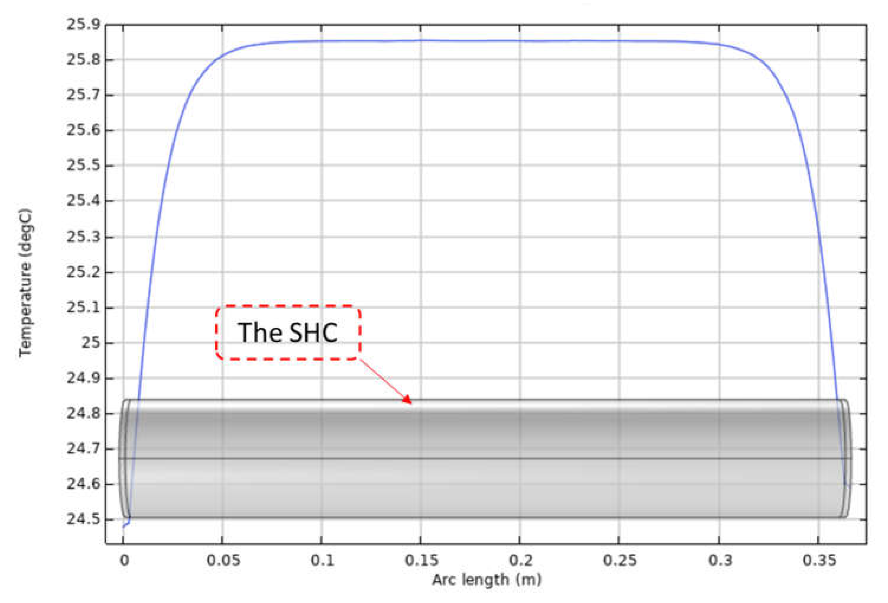
A steady-state three-dimensional (3D) thermal study has been conducted to understand the distribution of the temperature profile within the SHC. Moreover, a 1D line graph has been added to achieve that goal. The temperature profile inside the SHC is essential and critical, mainly when the thermomechanical actuator contains multiple SMA springs, as highlighted in the proposed design, since that affects the activation of each SMA spring and the performance of the thermomechanical actuator. The results of this study have been placed in
Figure 10, where the generated temperature is shown along the axial direction for the center of the actuator. Additionally, it has been observed from this study that there is a temperature difference of about 1.35 °C between the middle and side locations of the SHC. This result simulates the temperature variation within the SHC at noontime on 5 February 2022. This variation is expected to always stay the same through noontime, considering this orientation with differences in the magnitude of maximum (Max) and minimum (Min) values.
To increase the benefit of the SHC and reduce the temperature variation inside the SHC, the low-temperature areas inside the SHC should not contain the SMA spring.
Figure 11 shows the projection of these areas into the CAD model of the thermomechanical actuator, where 5 cm is taken from either side of the SHC. This 5 cm corresponds to about 13.8% of the total length. Moreover, considering this distance may lead to a notable effect when the variation in activation temperature in SMA springs remains relatively low. In addition to that, this consideration would provide better consistency of the activation of SMA springs subjected to uniform thermal energy, as well as minimize the difference in the activation time of the SMA springs that are integrated within the thermomechanical SMA actuator.
3.2. Optimized Orientation of the Thermomechanical Actuator on the Time-Dependent Temperature Distribution
Since the proposed thermomechanical SMA actuator is entirely dependent on passive energy given by the sun, a study for the optimized orientation of the actuator was considered. The external heat source from the sun that was applied is directional dependent, where the “X” axis direction represents the “North,” the “Y” axis direction represents the “West,” and the “Z” axis direction represents the “Zenith.”. Therefore, a time-dependent 3D thermal study has been carried out to indicate the main impact of various orientations on the temperature distributions of the actuator. Thus, this study shows the temperature variation in multiple orientations for the SHC at different times on 5 February 2022, where the studied setups are south-north, west-east, and zenith orientations.
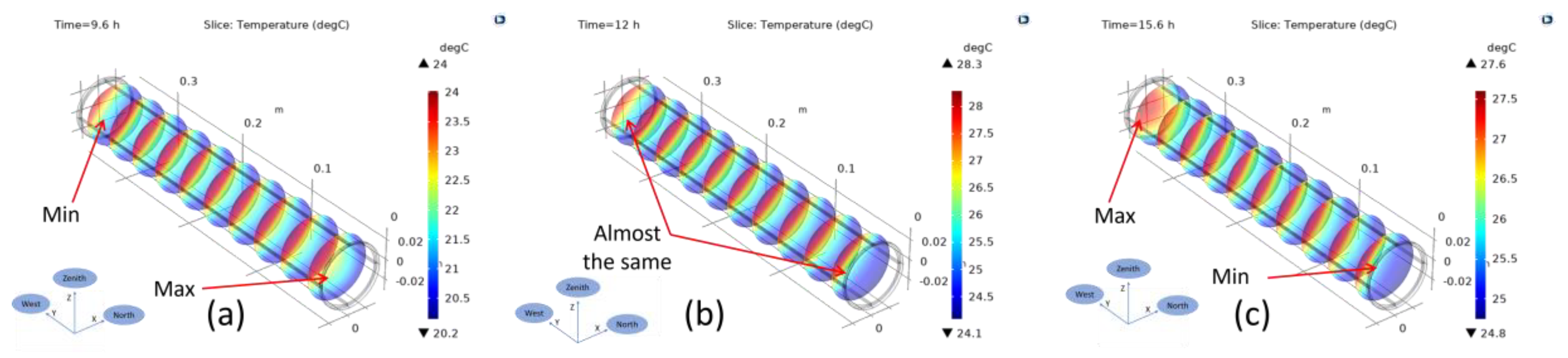
First, the long side of the SHC was oriented toward the south-north direction, while the end side was toward the west-east direction.
Figure 12 demonstrates the temperature distribution in this case, where the temperature distribution inside the SHC is shown at different times. In the morning (as seen in
Figure 12a), the temperature is Max on the right-hand side, since the sun is in the east direction. At noontime (as seen in
Figure 12b), all cross-sections have approximately a similar temperature distribution. Finally, after noontime (as seen in
Figure 12c), the left-hand side gains the most heat, because the sun is in the west direction. At all three times, the south direction has a greater temperature than the north, because of the sun’s location in the studied area of Dammam (since the KSA is in the northern hemisphere). The effect of this orientation is on a small cross-section at the ends of the SHC. Moreover, the Max temperature difference between one of the ends and the rest of the SHC is about 4 °C. This orientation may be acceptable because minimal areas have temperature differences (the ends).
Secondly, the long side of the SHC was oriented toward the west-east direction, while the ends toward the south-north direction, as seen in
Figure 13. The temperature distribution has shown a similar behavior, but for different SHC sides. The temperature was Max in the east direction at noontime and in the west direction after noontime. However, at noontime, the temperatures at the east and west were at the Min, but in the middle was at the Max. At all three times of the day, the south direction had a slightly higher temperature than the north. The difference between the north and the south direction was not significant, due to the fact that the relatively small cross-section was directed toward the sun rays (the SHC ends), and the angle of the sun in the south direction was not as large as the angle between the east and west (180°). The effect of this orientation occurred on a comparatively large cross-section area in the SHC, so this orientation may have had a noticeable impact on some of the SMA springs that would be used in the SHC. The difference between the Max temperature of one of the long sides and the rest of the SHC was about 4.5 °C. Additionally, this orientation may not be efficient in this solar-driven application, since the temperature difference that affects the large area within the SHC would cause a few SMA springs to be activated before others for a longer time.
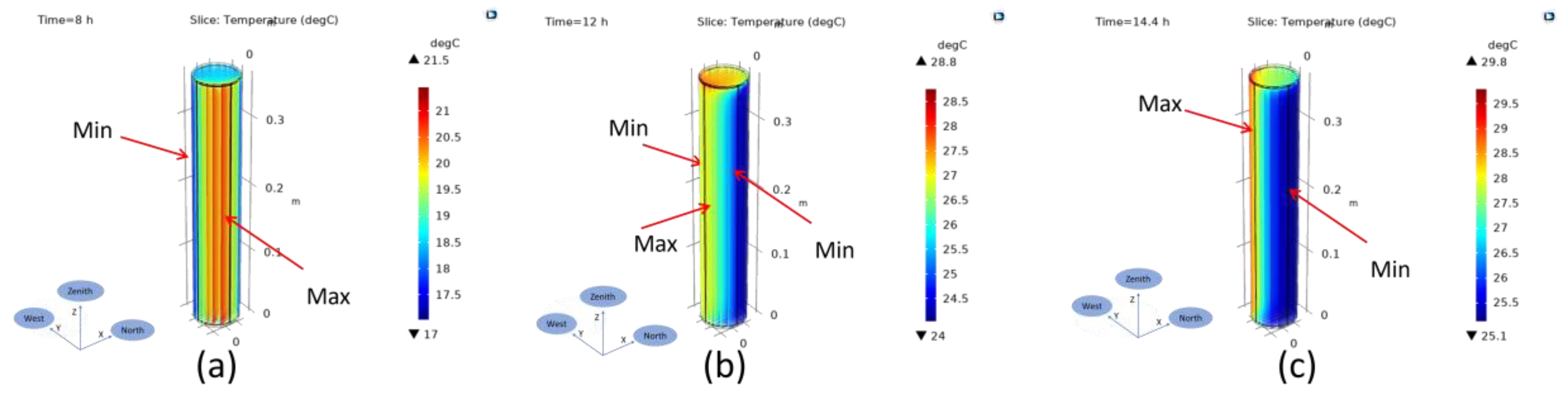
Finally, one of the ends of the SHC was oriented toward the zenith direction, as demonstrated in
Figure 14. The results indicate that, in the morning, the long east side of SHC has the Max temperature, and in the afternoon, it has the Max temperature in the opposite direction. Both the east and west long sides have Min temperatures at noontime, while the middle south long and upper sides have Max temperatures. The Max temperature difference between one of the long sides and the rest of the SHC is about 4.3 °C. This orientation affects a large cross-section area in the SHC. Thus, similar to the previous west-east orientation, this orientation may not be convenient to be used in this application, because the temperature difference that affects a large area inside the SHC would make synchronization and alignment challenges within the system, specifically when a few SMA springs are activated before other SMA springs. As a result, this part of the study found that the west-east (SHC ends) is the most convenient and efficient orientation to this solar-driven application since the temperature variation occurs in a small section area at the ends of the SHC, which is already empty of springs in the proposed design.
3.3. The Temperature Variation as a Time-Dependent
To ensure the optimal functionality of the proposed solar-driven thermomechanical SMA actuator, the introduced thermal study has been conducted and carried out to obtain a 3D time-dependent heat transfer study. This study gives the thermal behavior of the actuator under the actual weather conditions of Dammam, KSA, for a one-year period. In order to run this study, five points have been added in different locations within the SHC to understand their thermal profiles throughout the year, as seen in
Figure 15. This simulation study was carried out for this full Gregorian year of 2022.
In
Figure 16, the monthly temperature profile is shown for the SHC. The results show expected outcomes, since the temperature of the SHC is comparatively low in the winter (November till March) and high in the summer months (April till October), which indicates the close relevance and high accuracy of this simulation-based study. The rise and drop within the temperature profile are also shown; they occur smoothly day after day and month after month. The results show that the Max temperature profile occurs in June, July, and August, when the Max temperature reaches about 52 °C. On the contrary, the Min temperature profile occurs in January, when the Min temperature reaches about 14 °C. The temperatures of the top, left, center, bottom, and right were the highest most of the time throughout the year, respectively.
In order to reach a comprehensive understanding of the temperature profile in all 12 months of the 2022 year, the monthly average temperature profiles have been combined into one graph, which represents the temperature profile of the SHC in the whole year, as
Figure 17 displays. The graph shows a logical sequence for the temperature profile, in which the minimum temperatures occur in the first two months; thereafter, the temperature starts to increase until reaching the maximum in July and starting to decrease again. Additionally, zoomed areas have been added to the graph to provide a detailed view of the daily temperature profiles. The daily temperature profiles clearly indicate the temperature at different times of the day, in which the temperature starts to increase from the low point after the sunrise and reaches the maximum at the solar noon period, then starts to decrease again, reaching the low point of the day. The graph below shows a Max, Min, mean, median, range, and standard deviation values of 49.61 °C, 13.58 °C, 31. 03 °C, 31.20 °C, 36.03 °C, and 9.34 °C, respectively.
The yearly temperature profile is plotted, along with the average ambient temperature (as seen in
Figure 18), which has been extracted from the National Aeronautics and Space Administration (NASA) database [
56]. The average ambient temperature curve shows a behavior closely related to the behavior of the temperature profile of the SHC, with differences in the temperature magnitudes. This graph provides an important insight into the difference between the ambient temperature and maximum temperature within the SHC. This outcome is essential, due to the fact that it indicates how much the SHC has increased in temperature. The results demonstrate that the SHC can increase the temperature by approximately 10–15 °C.
A histogram plot of the yearly temperature profile of the SHC is shown in
Figure 19. It is seen that the temperature profile varies roughly from 13 °C to 50 °C. The graph demonstrates that most days, the temperature inside the SHC ranges from 34 °C to 36 °C, and few days have temperatures inside the SHC with less than 14 °C or above 48 °C. The results also show that the temperature profiles are not normally distributed with a right-skewed histogram, with most of the data are located under the normal distribution curve.
The variation in the temperature of the SMA springs is a crucial element since this variation is the primary way to activate and deactivate the SMA springs, as mentioned previously. In
Figure 20, the daily standard deviation and temperature variation are presented. It observed that there is at least a 10 °C difference between the maximum and minimum daily temperatures throughout the year. Additionally, it is noted that the temperature variation is at the maximum during the summer and hot days, while it is at the minimum during cold days. The daily standard deviation curve shown below indicates similar outcomes, in which the standard deviation is at the maximum during the summer days, and the opposite during the winter days within the studied region.
The frequency of the daily temperature variation can be seen in the histogram shown in
Figure 21. The graph shows that most of the days have temperature variation of 14.5 °C, which is considered a promising outcome, enabling the activation and de-activation of the thermomechanical actuator on a daily basis. On the other hand, it demonstrates that the minimum days have a daily temperature variation of only 10 and 17 °C. Additionally, it is also apparent in the graph that the temperature distribution data are not distributed normally, but they skew a little right.
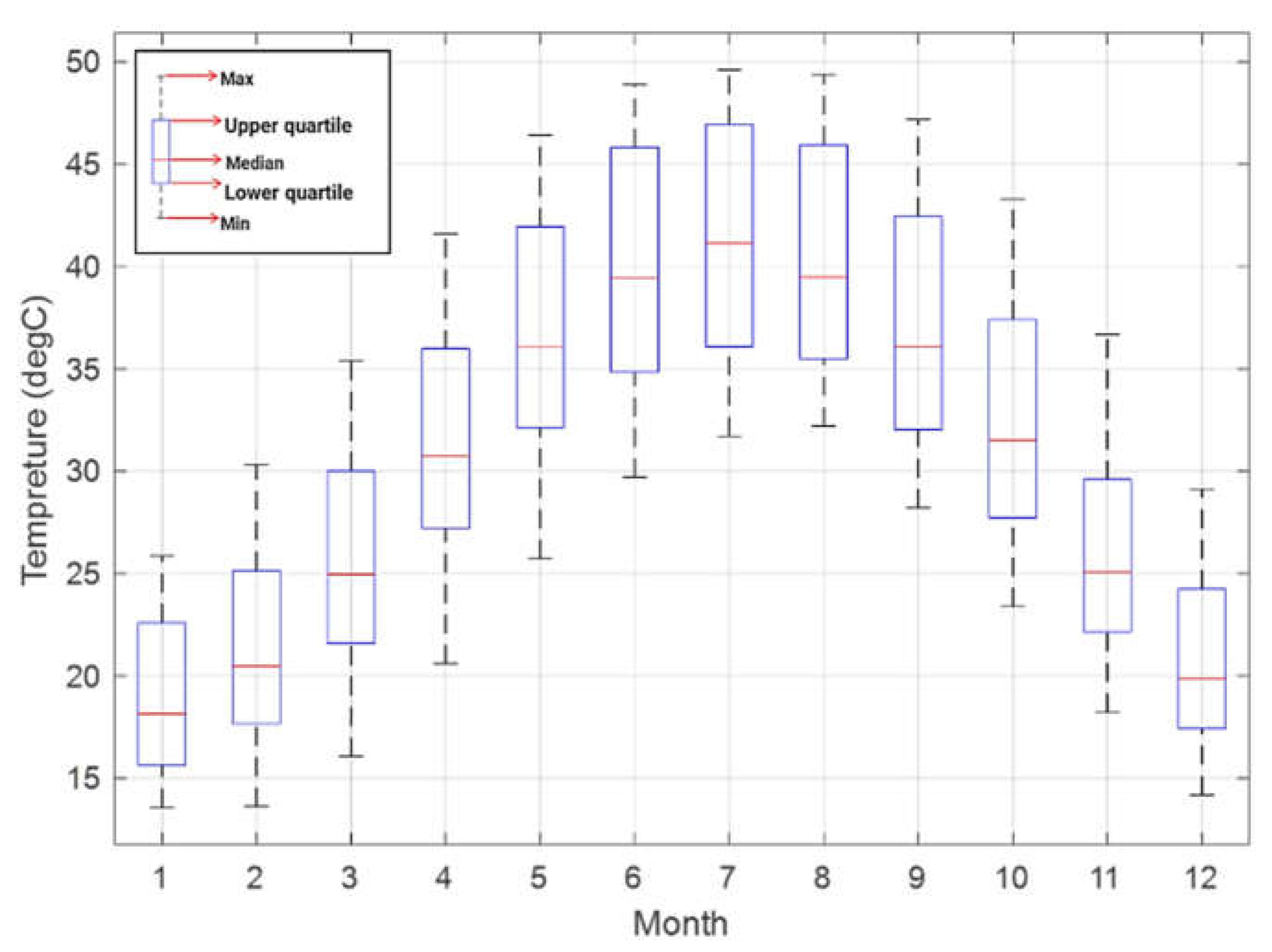
As daily temperature variation is one of the main concerns in this work, a detailed analysis of temperature data is essential. In
Figure 22 below, the monthly temperature inside the SHC is concluded in a box chart, where monthly Max, Min, Median, and upper and lower quartile temperatures are shown. This chart describes the daily temperature profile in a detailed statistical format. Moreover, the graph clarifies that some months have almost similar temperature profiles, and some have temperature profiles close to each other, while others have different temperature profiles. The months with varying profiles can form an obstacle for the thermomechanical actuator for a yearly operation, since common activation and de-activation temperatures cannot be reached within these months.
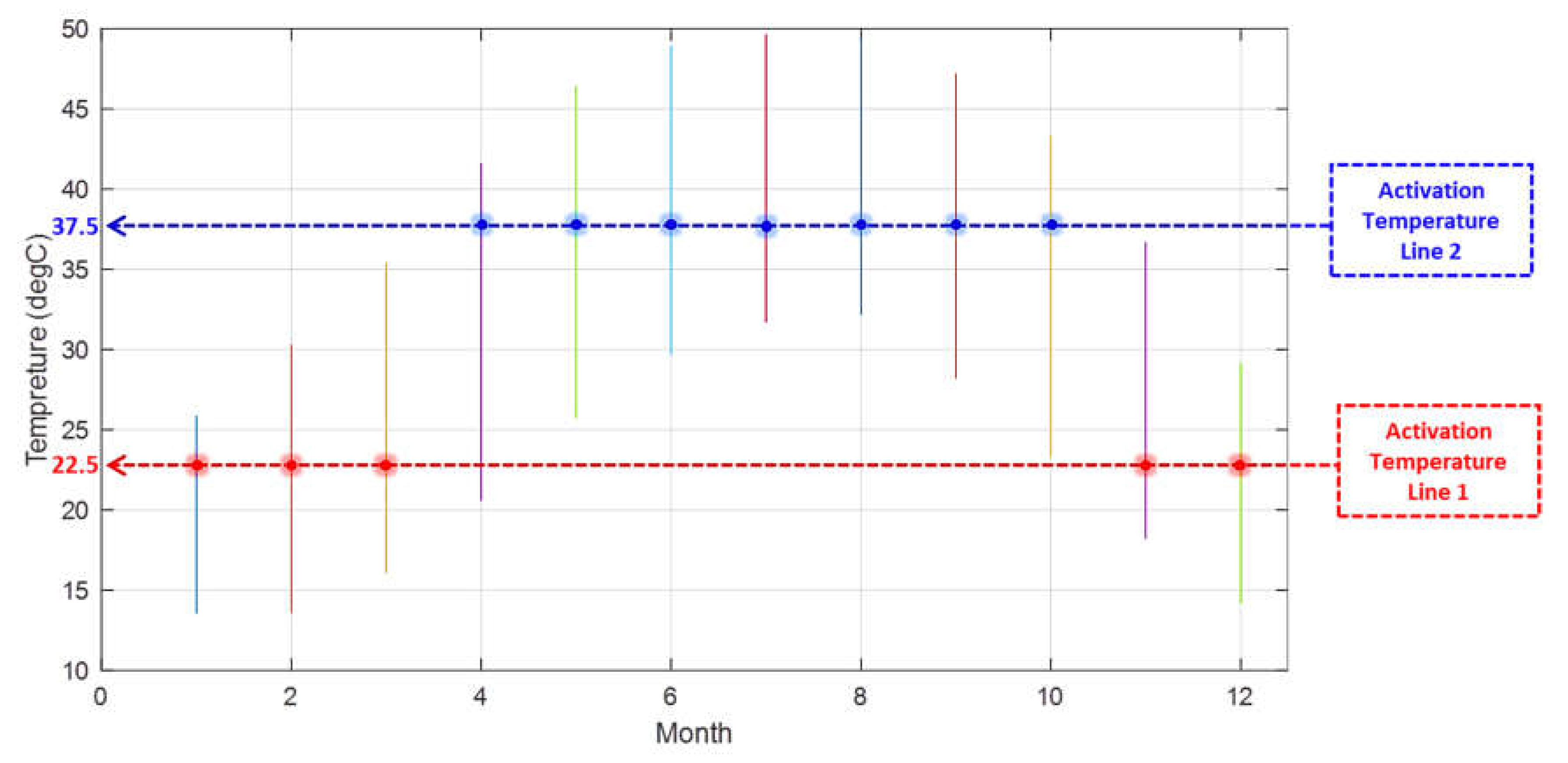
In order to overcome the challenge of temperature that has been mentioned, the monthly temperature inside the SHC has been plotted in a line graph, as seen in
Figure 23. After that, different activation temperature lines were added to the chart. The activation temperature lines represent the temperature at which the SMA springs would be activated in particular months. The fewer activation temperature lines there are, the better, since that means fewer SMA springs for which this activation temperature is needed.
Figure 23 displays the two activation temperatures that have been chosen for the SMA springs to activate the thermomechanical actuator. The activation temperature lines that have been selected are considered to be away from the maximum and minimum temperatures of the month, since not all days reach these upper and lower temperature levels, and therefore potentially prevent the proper activation and de-activation of the thermomechanical actuator throughout that month.
Therefore, it can be seen that the first activation temperature line is located where the temperature is about 22.5 °C. This activation temperature line is meant to activate the thermomechanical actuator in five months: January, February, March, November, and December. This activation temperature line is responsible for activating the thermomechanical actuator in the cold months, and it can be labeled as the lower activation temperature line.
The second activation temperature line is the line where the temperature is about 37.5 °C, which is more than the lower activation temperature line by 15 °C or 66.7%. This activation temperature line is meant to activate the thermomechanical actuator in the remaining seven months: April, May, June, July, August, September, and October. This activation temperature line is the reason for the activation of the thermomechanical actuator in the warm months, and it can be referred to as the upper activation temperature line. The lower and the upper activation temperature lines show the expected outcomes for the studied area since the KSA has long summer days; therefore, the upper activation temperature line corresponds to seven months, while the lower activation temperature line corresponds to just five months.
Knowing the suitable monthly activation temperature would help customize the appropriate SMA springs set. In the case of this study, it can be concluded that only two sets of SMA springs are needed, one with an activation temperature of 22.5 °C, and the other with an activation temperature of 37.5 °C. This means that the solar-driven thermomechanical actuator needs to have maintenance twice per year in order to be self-operating throughout the year. Furthermore, in order to make use of this actuator worldwide, a similar study and procedure can be adopted, in which the monthly temperature profile is computed and analyzed. Accordingly, the activation temperature lines should be constructed. The activation temperature lines should be located below the monthly maximum temperature, where the closer to the mean value they are, the better. This line should be extended to have the maximum number of months. It is important to note that some months have no potential to have the same activation temperature as others; for example, in January and July in this study, since the maximum temperature inside the SHC in January is much lower than the minimum within the SHC for July. The optimization in finding the activation temperature lines would lead to a decrease in the number of sets of the SMA springs needed, hence decreasing the number of required maintenance cycles per year and then decreasing the associated cost of maintenance for this self-driven solar-based thermomechanical actuator.


