You are currently viewing a new version of our website. To view the old version click .
Sustainability
  • Article
  • Open Access

18 April 2022

Evaluating the Flow Accelerated Corrosion and Erosion–Corrosion Behavior of a Pipeline Grade Carbon Steel (AISI 1030) for Sustainable Operations

,
,
and
1
Department of Mechanical Engineering, King Fahd University of Petroleum & Minerals (KFUPM), Dhahran 31261, Saudi Arabia
2
Faculty of Materials and Chemical Engineering, Ghulam Ishaq Khan Institute of Engineering Sciences and Technology, Topi 23640, Pakistan
3
Interdisciplinary Research Center for Advanced Materials, King Fahd University of Petroleum & Minerals (KFUPM), Dhahran 31261, Saudi Arabia
*
Author to whom correspondence should be addressed.

Abstract

Erosion–corrosion behavior of pipeline grade carbon steel alloy (AISI 1030) was investigated using a state-of-the-art jet impingement flow loop. Different impingement velocities (3 to 12 m/s) and angles (15°, 30°, 45°, 60°, and 90°) were employed (with/without sand particles) to study the degradation behavior of this pipeline grade steel in 0.2 M NaCl solution at room temperature. Experiments were conducted for a duration of 24 h at room temperature. The maximum erosion–corrosion (EC) rate was observed at an impingement angle of 45° at all velocities (3 to 12 m/s), as both the shear and normal impact stresses were of the same order of magnitude at this angle. At lower impingement angles, the effect of shear stress was more dominant and vice versa at higher impingement angles. The synergistic affect was found to be maximum at 45° due to enhancement of erosion by corrosion and/or corrosion by erosion. Ploughing, deep craters, raised lips, dimples, micro-forging/plastic deformation, and extrusion were the dominant erosion–corrosion mechanisms as observed by Field Emission Scanning Electron Microscopy (FE-SEM). The maximum corrosion wear scar depth was found to be 57 µm (average) at an impingement angle of 45°, as measured using an optical profilometer. The obtained results are very significant and can be used in process parameter optimizations to enhance infrastructure reliability. These results will also be the part of in-house database to develop a comprehensive erosion and erosion–corrosion model for erosion–corrosion prediction of different materials under various operational conditions.

1. Introduction

Material degradation in the form of erosion–corrosion in oil and gas facilities, desalination, power plants, and other related industries, has a direct impact on infrastructure reliability [1,2,3]. Erosion–corrosion is a common occurrence in fluid handling systems and considered as an important degradation challenge to ensure sustainable operations [4,5,6,7,8]. Flow accelerated corrosion (FAC) is primarily an electrochemical corrosion process in which both the chemical dissolution and mass transfer are involved. In this type of corrosion, protective oxide film is dissolved into the flowing fluid and the film becomes thinner and less protective. The oxide film is thinned to an extent that bare metal surface is exposed and even with the presence of an intact oxide film, the rate of metal dissolution gets accelerated at higher velocities, as the quality of the film has degraded considerably. Corrosion rate in FAC is increased by chemical dissolution/mass transfer, while the contribution of the mechanical component is not dominant. Researchers investigated FAC in systems with sudden changes in flow direction and found that mass transfer is directly proportional to corrosion rate with dependence of flow geometry [9]. Jet impingement is an attractive tool to study FAC, as flow is targeted across a surface to produce high mass transfer [10]. On the other hand, erosion–corrosion is a material degradation process in which the material is removed by the mechanical process of erosion coupled with the electrochemical process of corrosion and is responsible for many premature equipment failures [11]. Impingement corrosion is a special form of erosion–corrosion generally attributed to the local impingement of a high velocity flowing fluid against a solid/target surface. This type of corrosion usually has a specific pattern of localized attack with directional features. The responsible mechanism for impingement corrosion can be similar to that of erosion–corrosion and/or flow accelerated corrosion, depending upon the presence/absence of solid particles.
Fluid transportation (oil and gas, chemical, seawater, and other aggressive fluids) is a key component in accomplishing the processing and operational requirements, and fluid transportation is an essential process. The reservoirs fluids may have solid particles, which are responsible for the erosion wear damage to the inner surfaces of the equipment (pumps, compressors, tubulars, etc.). Sand particles are also present in crude oil, associated produced water, and in systems utilizing seawater for cooling purposes. When high velocity solid particles strike the stationary and rotating equipment, they damage the surface, which results in unplanned equipment failures/repairs and plant shutdowns [12]. The flow geometries significantly decrease/affect the wall thickness by continuously removing the corrosion product, and this will ultimately contribute to failures and may result in catastrophic failures. Therefore, careful simulation of erosion–corrosion processes under different conditions of material/environment interactions enable the selection of the most suitable material for a particular application and/or the ability to devise a suitable protection strategy for sustainable operations. The most realistic and reliable experimental results that can predict the erosion–corrosion rate in pipelines require state-of-the art experimental facilities to simulate actual process conditions. Such facilities include especially designed experimental rigs/flow loops with variety of test cell designs. However, such test facilities are expensive and not common in research.
As per ASTM G73-98, liquid (droplet) impingement erosion is the progressive loss of the material due to continued exposure to impacts by liquid jets. Usually, the problems arise when a stream of water impinges on or flows over components whenever there is a change of flow direction and/or a change in the cross-sectional area of the flow passage. The consequent deterioration process is exacerbated when the aqueous fluid itself is corrosive, as under such conditions (combination of electrochemical and mechanical interactions) the process becomes very complex [13,14,15]. Mechanisms associated with the material loss can vary depending on how the material is removed from the surface. It can be removed by chemical dissolution, or by erosion owing to fluid flow or by the impingement of slurry mixed with solid particles. There can be more intricate situations in which electrochemical corrosion can have synergistic effects [16,17]. As proposed elsewhere [9,18], the synergistic effects of erosion–corrosion can be considerably higher than the individual effect of corrosion or erosion. Additionally, it is reported that in different types of materials, the synergistic effect of stress and corrosion controls the loss of materials in the solution under consideration [19,20,21].
The published literature rarely reported the synergistic effect of impingement erosion–corrosion of AISI 1030 pipeline grade steel under a range of operating conditions (i.e., fluid velocity and angular trajectories along with/without the presence of solid particles). Therefore, the broader objective of this ongoing research work was to generate a comprehensive in-house erosion–corrosion database, which will ultimately lead towards the development of an erosion–corrosion mathematical model for different steel grades (low carbon to high carbon steel, stainless steels, etc.) under different environmental and processing conditions (range of variables) [22,23]. Table 1 shows a comparison of synergist affect among different types of materials when tested under a variety of conditions, including this study. It is quite obvious that that the range of parametric investigation is quite comprehensive and broad in this work. Flow accelerated corrosion is usually a phenomenon observed under single phase flow conditions, however the presence of solid particles in the fluid causes a simultaneous action of erosion and corrosion. The material loss due to this combined action of erosion–corrosion is considerably higher than the individual effect of each of these processes. This sort of synergism between mechanical and electrochemical processes can complicate the situation and it becomes quite difficult to predict the actual erosion–corrosion rates of the materials. Therefore, in this work, we are reporting the erosion–corrosion behavior and underlying impingement erosion–corrosion mechanism of a medium carbon steel (AISI 1030). The experiments were conducted to examine the role of various parameters such as impingement velocity (3~12 m/s) and impingement angle (15°~90°) on the impingement erosion–corrosion in 0.2 M NaCl solution at room temperature (23–26 °C) with/without solid particles for a duration of 24 h.
Table 1. A comparison of synergistic effect among different materials under different test conditions.

2. Materials and Methods

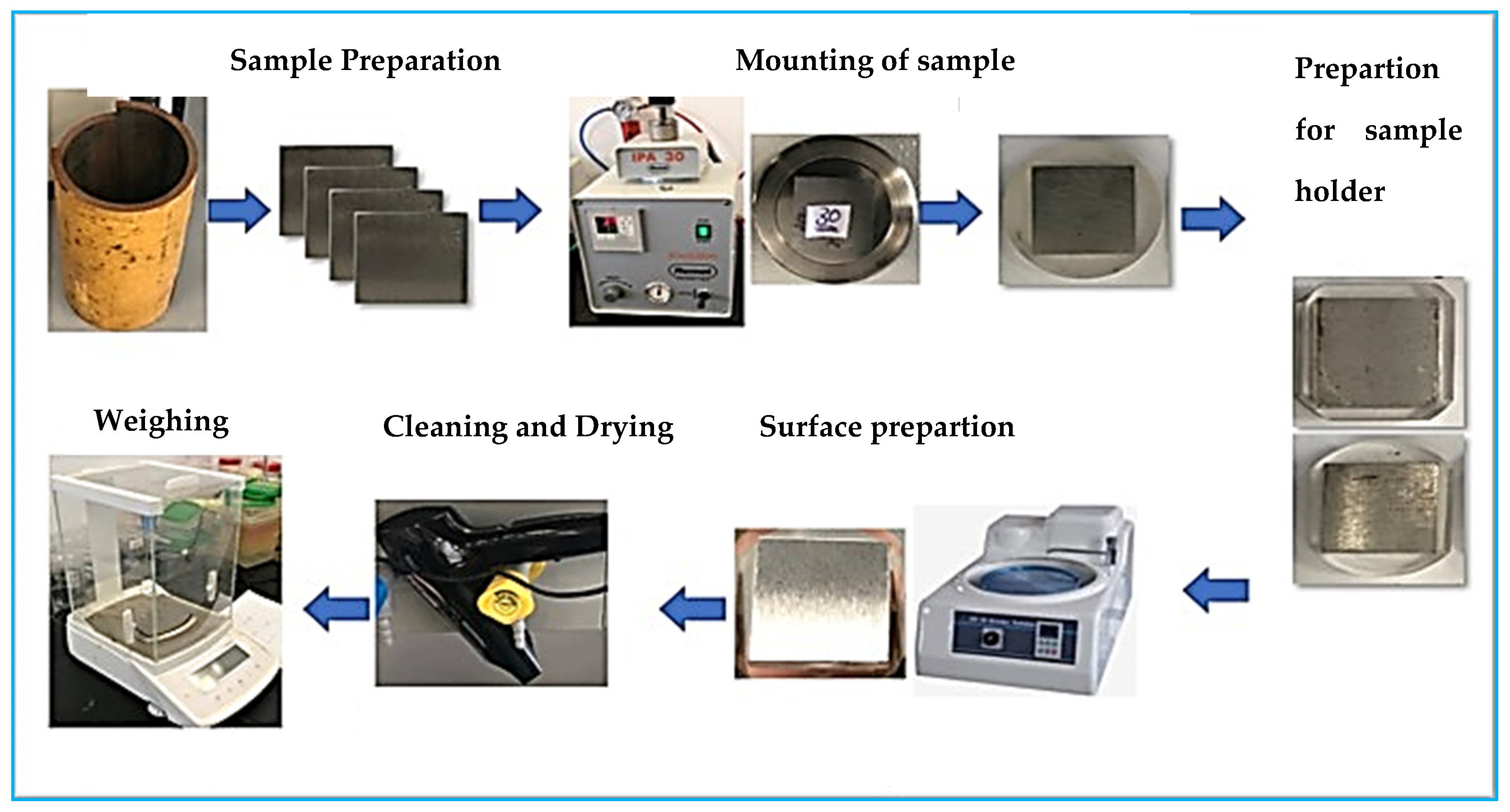
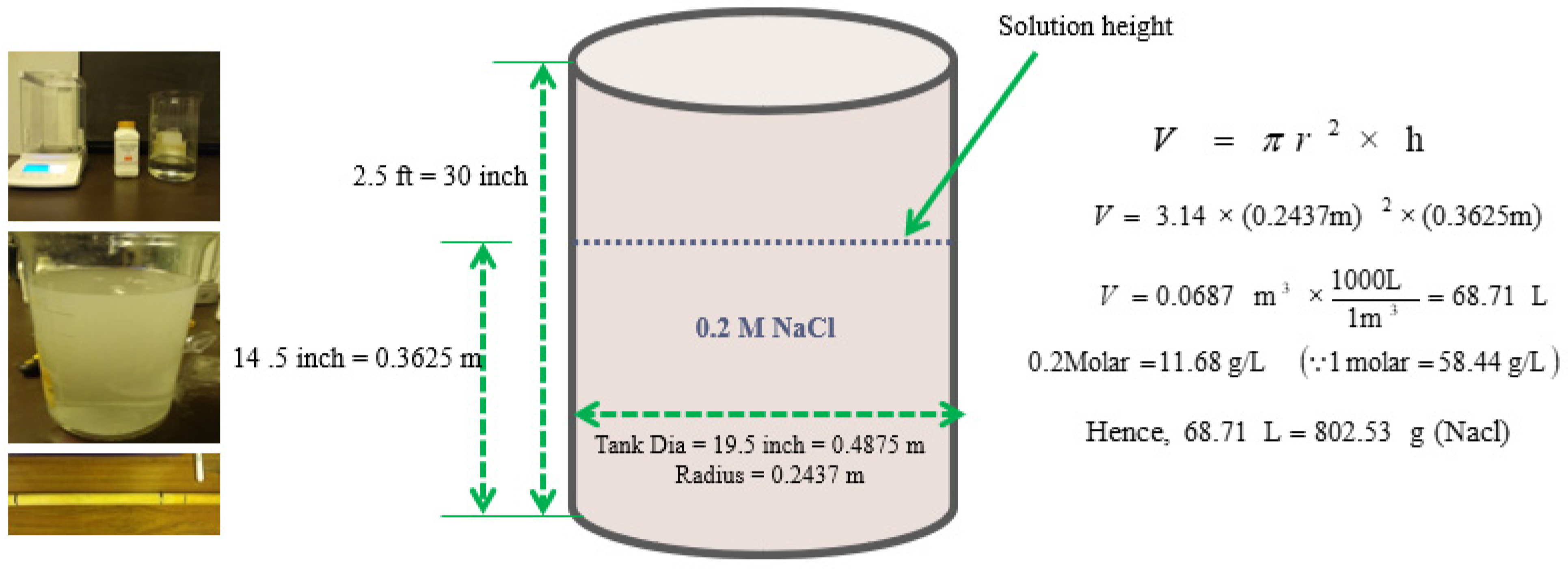
2.1. Erosion–Corrosion Test Apparatus and Material Preparation

A 316 L stainless steel multipurpose, state-of-the art flow loop (Figure 1) was manufactured to carry out the detailed experimental investigations. This special purpose loop has a centrifugal pump (with variable speed controller), two test cells (which can be adjusted up to six different angles, i.e., 15°~90°), and a solution storage tank. The required liquid impingement velocity was achieved using 316 L/3 mm diameter nozzle. A hydrocyclone and an injector was used to control the sand injection, collection, and separation to avoid pump erosion due to sand particles. A gas diffuser can be installed inside the tank for purging different gases (if required) such as N2, O2, Ar, CO2, etc. A pH controller can be used to monitor and control the pH of the solution, along with dissolved oxygen analyzer. An ultrasonic flowmeter was employed for liquid jet velocity calculations. A 15 kW pump was installed and a 650 V SSD drive control panel was used to control the speed of the pump [22,23].
Figure 1. (a) The flow loop used in the experiments, its components and instrumentation, (b,c) Specimen holder and contact angle.
Impingement corrosion (without solid particles) and erosion–corrosion (with solid particles) tests were performed on AISI 1030 carbon steel (C = 0.30, Mn = 0.65, Cu = 0.14, and Fe = more than 98 wt.%), a common piping material for transportation of fluids in petroleum, desalination, and many other industrial applications. It has distinct physical properties with appreciable ductility, potentially high strength, weldability, and amenability to heat treatment. The average Vickers hardness (HV) was measured at room temperature using a CSM Micro Combi hardness tester (Diamond indenter) under 2 N loads (P) over an indentation time of 10 s and was found to be 304 HV.
Sand particles (in the range of 125~704 µm) with an average particle size of 314 µm were used for the erosion–corrosion investigations (Figure 2). These silica sand particles were from the Riyadh region of Saudi Arabia and supplied by the BMS Company, based in Jeddah. To obtain a sand concentration of 500 ppm, 33.5 g of sand was used in 69 L of solution. Sand particles were introduced through the inlet near the temperature gauge before the specimen chamber.
Figure 2. FESEM images showing the Silica sand particles used as abrasive material (a) Particle size and morphology, (b) Particle size distribution.
Tests were conducted under free jet conditions and the size of the jet was 3 mm. Lucite (acrylic) material was used to hot mount the specimens (20 × 20 × 5 mm thickness) with an exposed surface area of 20 × 20 (mm2) and subsequently ground using 600 grit size emery paper. Acrylic material was selected for hot mounting to avoid any galvanic coupling between the specimen holder (made of stainless steel 316) and carbon steel samples. By doing so, any direct contact of tested samples with the SS 316 holder was eliminated. Before weight loss measurements, samples were dried with the drier for at least 10 min to eliminate any trapped water content) to an accuracy of 0.01 mg. The details of the specimen preparation before and after the experiment are presented in Figure 3. Approximately 69 L of 0.2 M test solution was prepared by dissolving about 800 g of NaCl in tap water from sweet water line. Water analysis using an ultrameter showed that the contents of total dissolved solid (TDS) and chloride ion content were found to be 160 ppm and 140 ppm, respectively, with a pH of 7.5 (solution preparation details are shown in Figure 4).
Figure 3. Steps involved in specimen preparation before and after the experiments.
Figure 4. Details of solution preparation for the experiments.
An optical profilometer from Bruker was used to measure the surface roughness of the specimens after the experiments. Optical profilometer helps in scanning the required area to measure the scar depth and presents the data in the form of 3D profiles. If required, 2D profiles can be generated once 3D profiles are measured. The scar mark of interest is traversed across to get the 2D profile of that scar mark. The samples were cleaned with acetone, rinsed with distilled water, and subsequently dried before conducting each experiment.

2.2. Test Procedure

The experiments were performed according to ASTM-G-73-98 in neutral chloride solution (0.2 M NaCl solution). Five different angles (i.e., 15°, 30°, 45°, 60°, and 90°) were investigated at three different velocities, i.e., 3 m/s, 6 m/s, and 12 m/s, respectively, for a duration of 24 h. Weight loss method (Equation (1)) was used for erosion–corrosion rate calculations as per ASTM G1-03. The weight loss after erosion–corrosion tests was measured using a digital balance with an accuracy of 0.01 mg. The experiments were performed thrice under each experimental condition for data repeatability.
Corrosion   Rate   = Weight   loss   ( mg )   ×   K Density   of   sample   ( g / cm 3 )   ×   Exposed   Area   ( cm 2 )   ×   Exposure   time   ( h )  
where K is a constant and different values can be used to measure the corrosion rate in required units. A value of 3.45 × 10⁶ is used here to calculate the corrosion rate in mils per year.

3. Results

Figure 5 shows the effect of impingement angle on the impingement corrosion behavior of the AISI 1030 carbon steel in 0.2 M NaCl solution (without solid particles) at 3 m/s velocity. It is clear from Figure 5 that the maximum impingement corrosion rate was observed between 30°~60° angles, which is typical of a behavior observed in ductile materials. Material removal occurs through displacement and cutting of the erodent on the target material in ductile materialcompared to brittle materials, in which material removal is achieved through intersection and propagation of cracks and subsequent material removal [27,28]. During fluid impingement, both the shearing and normal stresses come into play, and they change the corrosion rate as a function of impingement angle. It is widely reported that the shearing stress is dominant at lower angles and the impact stress is more dominant at higher angles. However, at 45° there is a balance between these two stresses, so therefore the maximum impingement corrosion rate observed at this intermediate angle [29] reported the maximum corrosion rate of carbon steel at about 45° while investigating the dependence of carbon steel erosion–corrosion rate on the specimen angle.
Figure 5. Effect of impingement angle on impingement corrosion rate of AISI 1030 carbon steel.

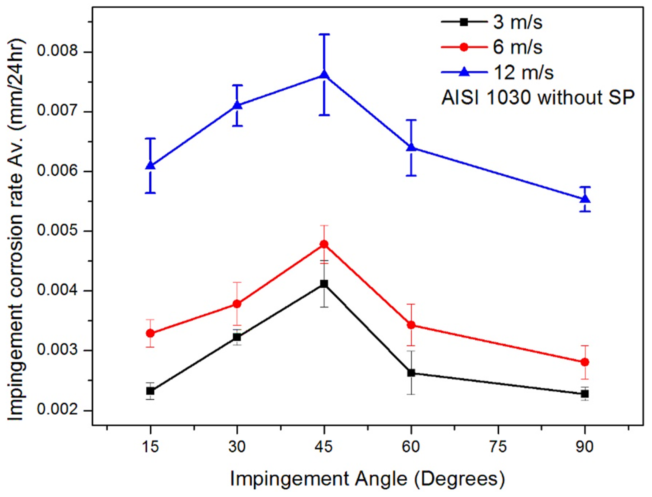
3.1. Effect of Jet Velocity on Impingement Corrosion (No Solid Particles)

Figure 6 shows the effect of fluid velocity on impingement corrosion of AISI 1030 carbon steel and it is clear that corrosion rate was increased with an increase in fluid velocity. This increase was attributed to an increase in the stresses on wall surface of target material. It is reported in the literature that wall shear stresses on specimen surface increase rapidly with an increase in fluid jet velocity and this will contribute to an increased mass transfer rate from specimen surface. It is one of the key factors contributing towards higher corrosion rate at high fluid jet velocities. During the experiments conducted, it was also observed that there was a continuous removal of corrosion products from specimen surface by fluid movement. With an increase in fluid velocity, the mass transport of oxygen to the surface is also increased and that subsequently increases the corrosion rate of the material [30]. The specimen surface corrosion pattern and corrosion scars resulting from fluid impingement clearly show the direction of fluid movement (Figure 7). The regions close to the impingement point were further examined using SEM and optical profilometers.
Figure 6. Effect of different impingement velocities on impingement corrosion rate of AISI 1030 (UNS G10300) carbon steel.
Figure 7. (a) Carbon steel specimen before experiment, (b) Effect of impingement velocity/angle on the specimen surface.

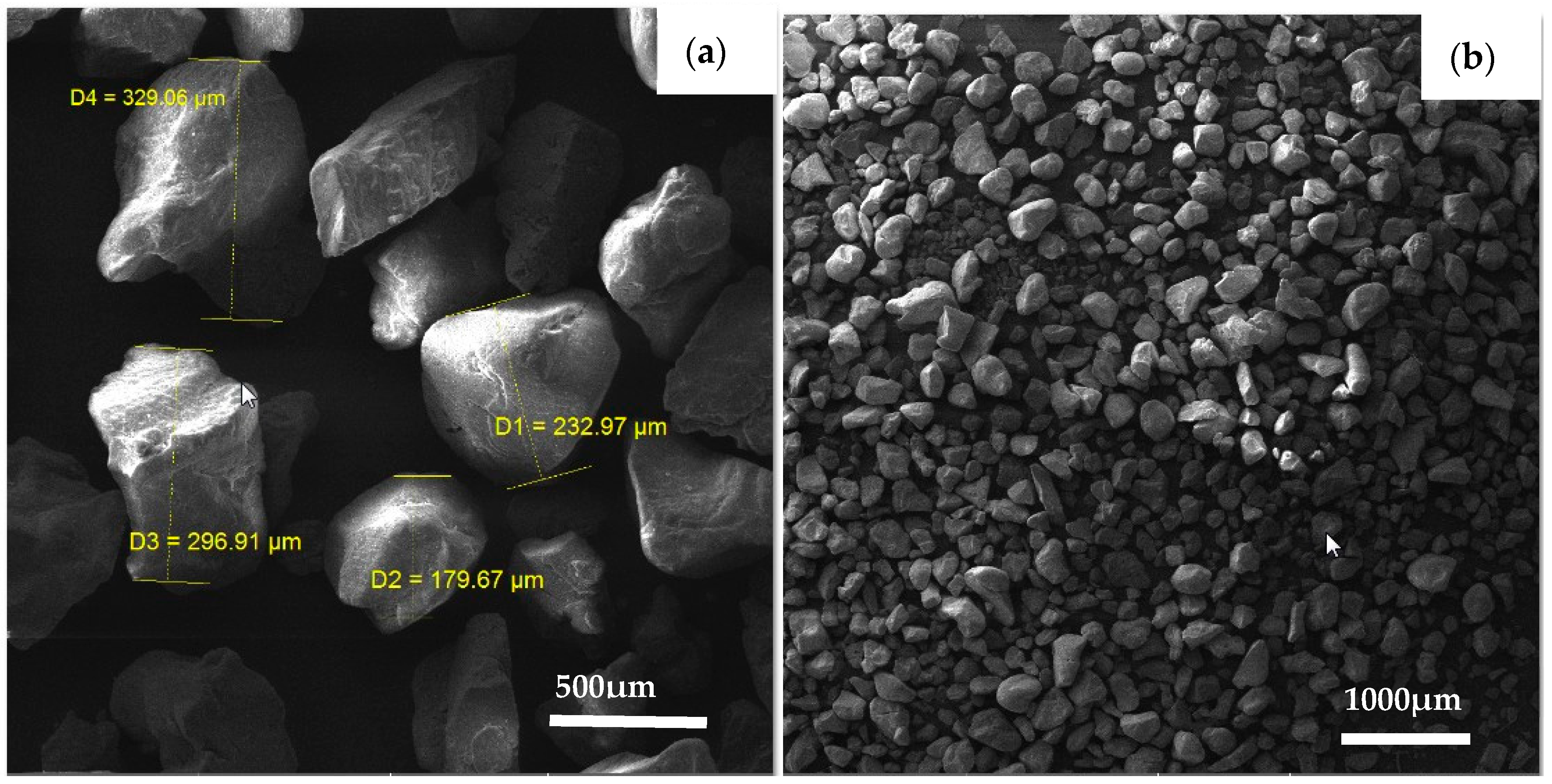
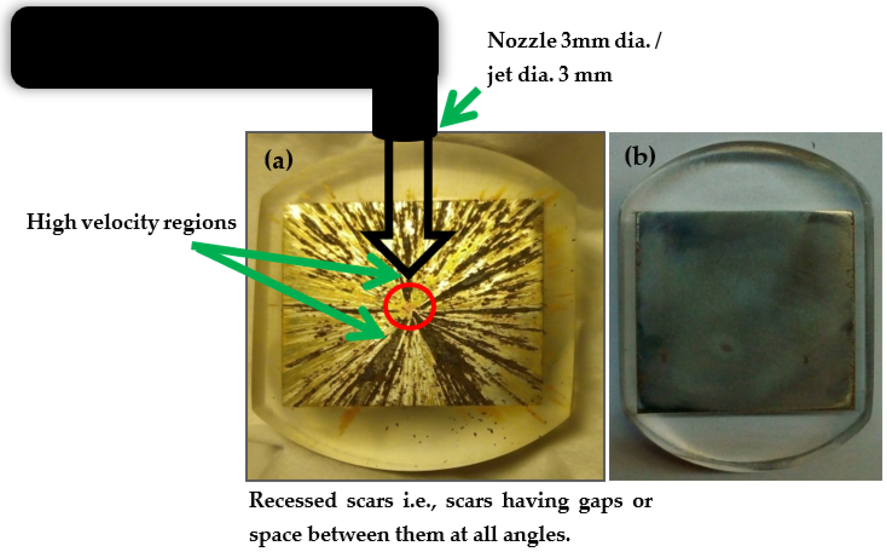
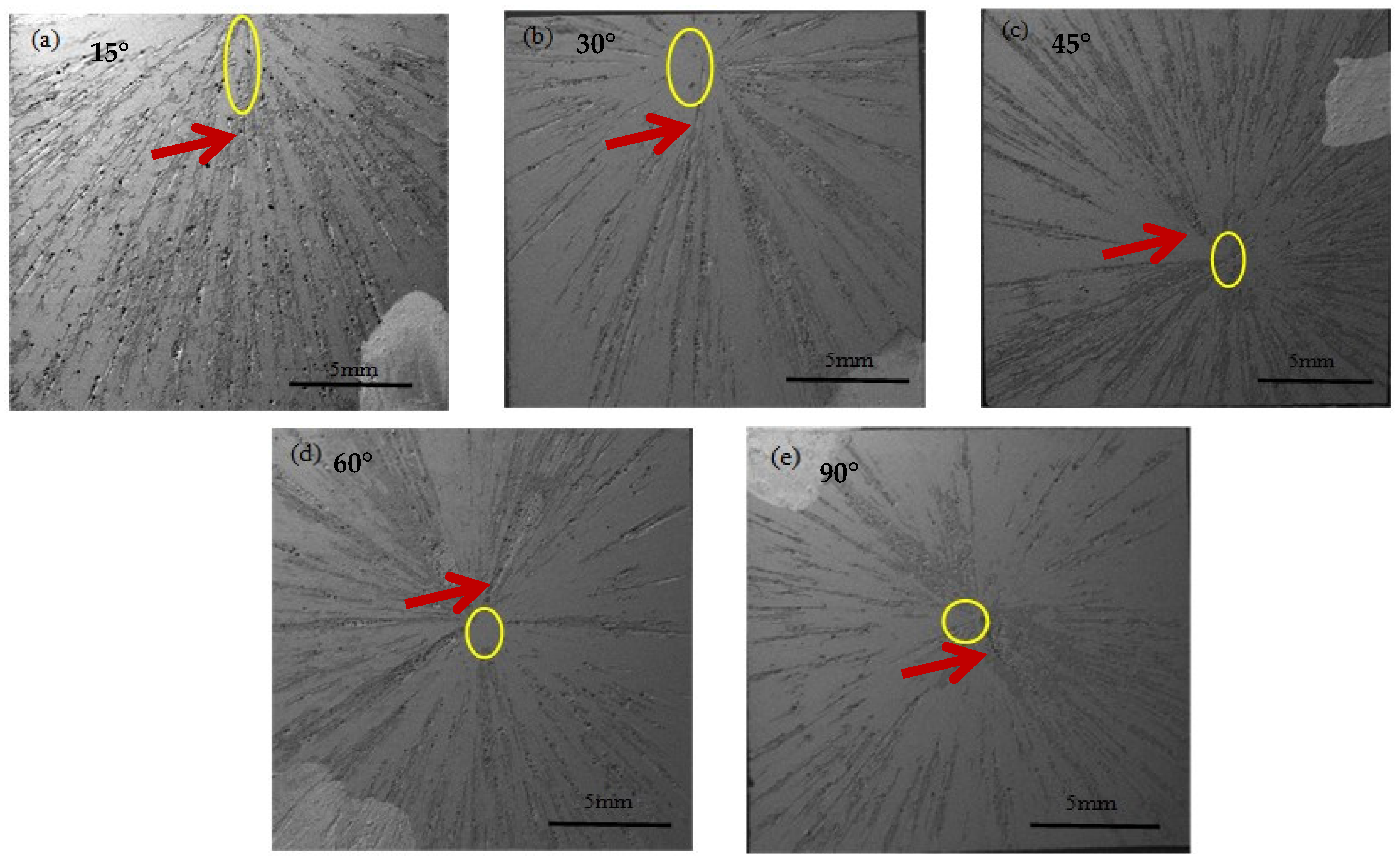
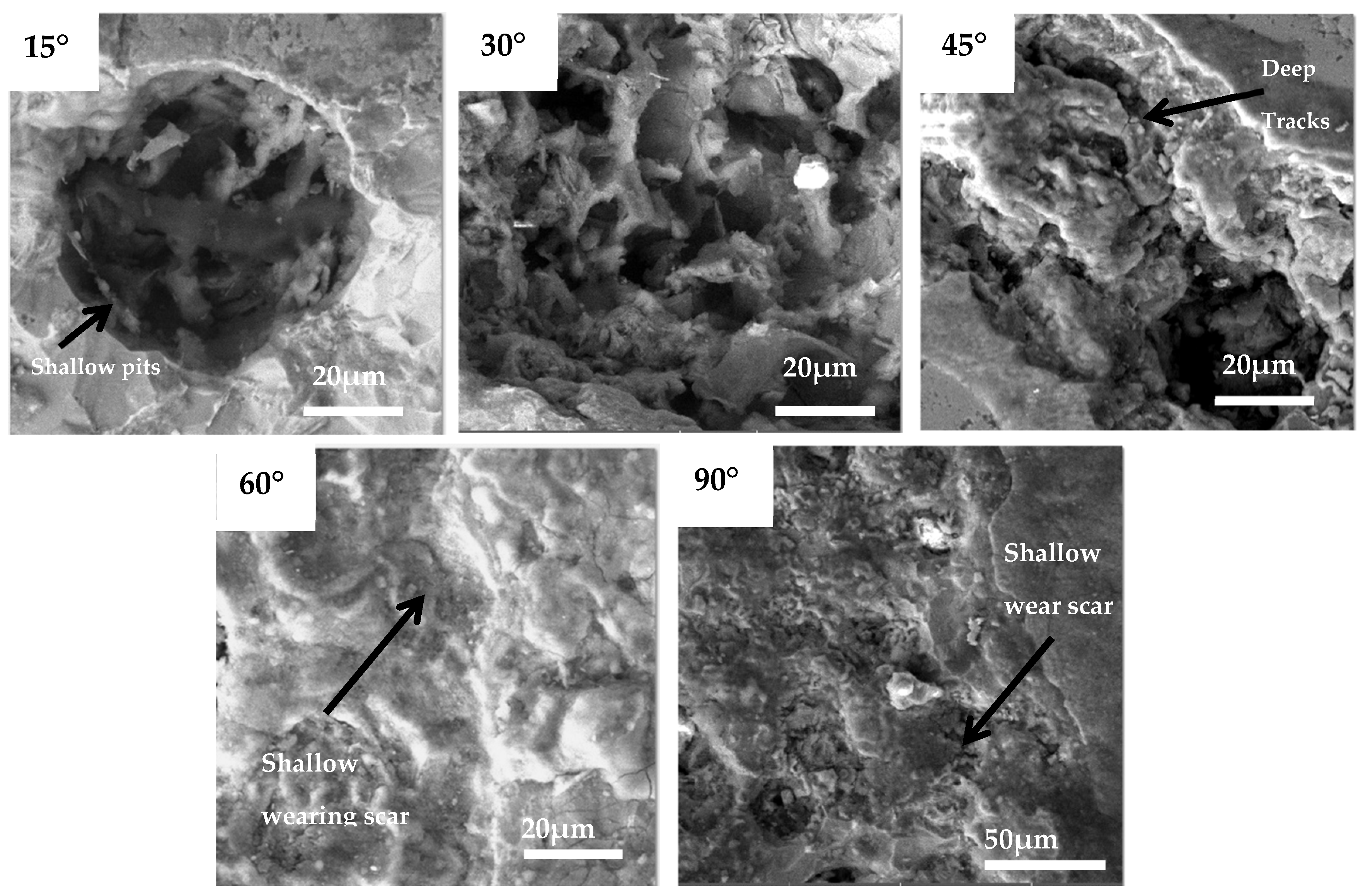
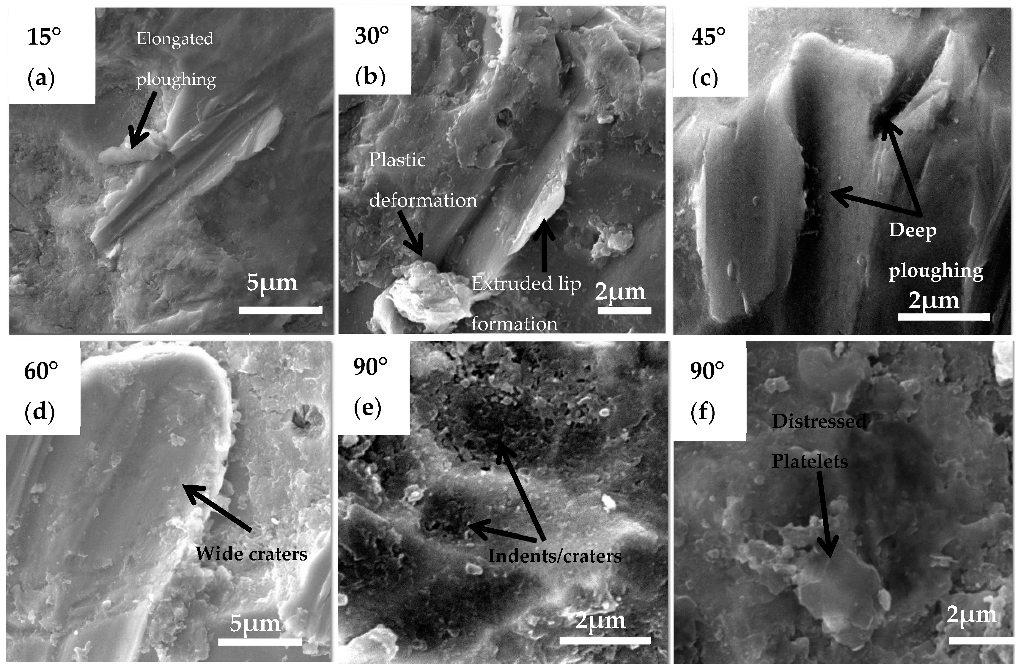
3.2. Surface Morphology and Corrosion Scar Features

Figure 8a–e shows the SEM images of the specimens after the impingement corrosion experiments were conducted at 15°~90° angle, respectively. The number of corrosion patterns, corrosion scar morphologies, and their depths varied with the change of impingement angles. These morphologies clearly demonstrated the way fluid flowed over the specimen surface. The corrosion scar depth is the distance from the deepest point within the damaged zone to the unaffected surface of the specimen. The unaffected surface was taken as a reference plane and set at zero. The impingement point (circled in yellow in Figure 8a–e) was more elliptical at a lower angle and became circular at 90° angle. This change was evidence of the fact that a different type of impact stress was acting at different angles, i.e., shearing stress at oblique angles and impact stress at higher angles. It is interesting to note that the impingement points seemed unaffected by the fluid impact, mainly because of the possible stagnation zone at impingement points. It was also observed that at lower impingement angles, i.e., 15°, the fluid spreads over the uniformly over the specimen surface without having a significant drop in the fluid velocity [29]. Based on the above discussion, it can be deduced that shearing stress component of the fluid was maximum at such low angles. Furthermore, the wear scars at this angle were found not to be continuous and shallower when compared with those observed at angles in between 30° and 60° (Figure 7 and Figure 8). Shallow pitting was observed at lower angles all over the surface. The greater pitting susceptibility under oblique angles can be correlated to many factors such as the availability of increased bare surface due to fluid flow at such angles, the presence of rough surface created by the dominant shearing component at lower angles, and the presence of surface inclusions/defects in the metal surface [31].
Figure 8. FESEM images (ae) of corrosion scars after impingement corrosion experiments at 15~90° angles (red arrows show high velocity regions).
The corrosion scars observed at 30° were found to be wider, deeper, and continuous as compared to those observed at 15° as shown in Figure 8b. On the other hand, at 45° angle (Figure 8c), the number of corrosion scars and the total effected area was more as compared to what was observed at angles either <45° or >45°. It was also noted that the scars at 45° were continuous towards the boundary of the specimen. Such a trend in corrosion scar morphology was expected due to the balanced effect of both shear and impact stresses at 45° impingement angle. Such a balance will cause the highest impingement corrosion. At impact angles > 45°, the normal impact component became more dominant (Figure 8d) and so therefore the corrosion scars were found to be shallower and lesser in numbers at 60° impingement angle. Furthermore, at a 90° angle, the effect of normal impact stress was maximum, and the fluid lost most of its energy after the impact, as shown in Figure 8e. This resulted in a minor surface corrosion (electrochemical corrosion) without any significant deep pitting, as shown in Figure 9. It is clear from Figure 9 that electrochemical corrosion was more severe when the impingement angle was at 45° as deep tracks were observed on the surface due to corrosion. The corrosion scars and their penetration depths were examined and verified using an optical profilometer, as presented in Section 3.5.
Figure 9. FESEM images showing the corrosion scar morphology after impingement corrosion experiments at 15–90° angles.

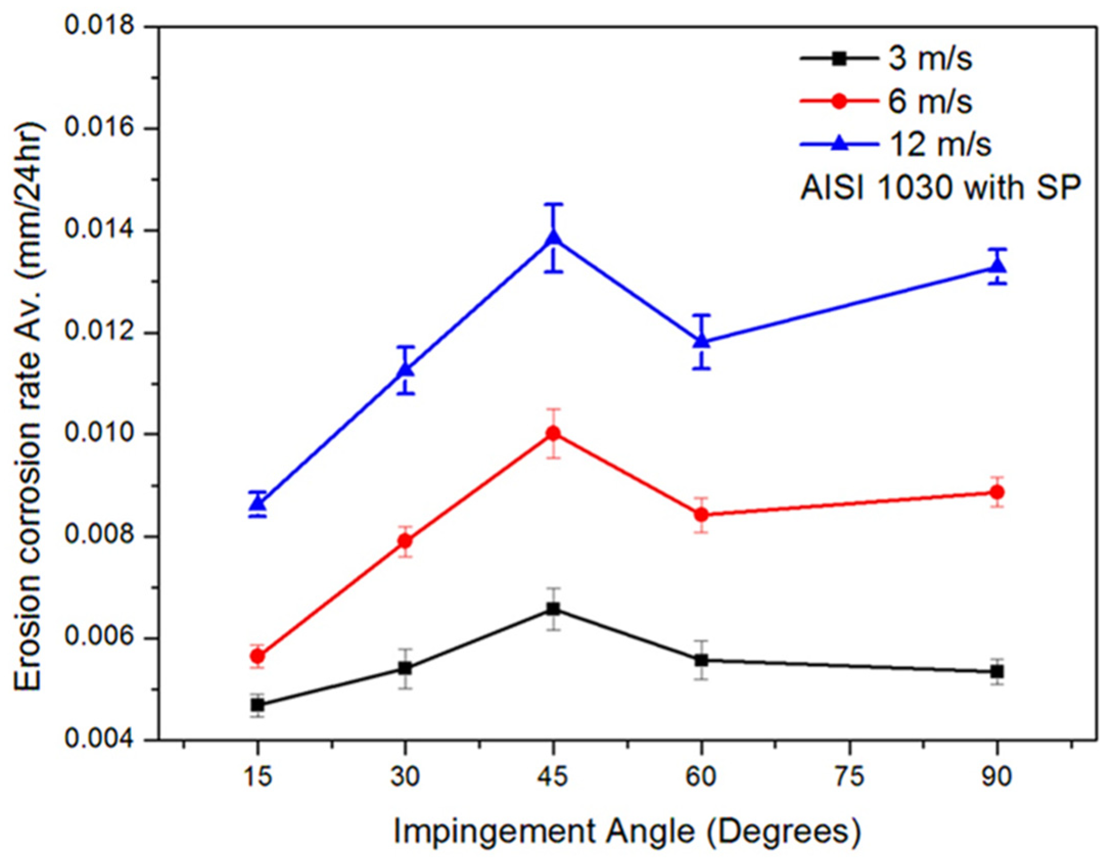
3.3. Effect of Jet Velocity and Angle on Erosion–Corrosion (with Solid Particles)

This section shows the effect of solid particles, impingement angle, and velocity on the erosion–corrosion behavior of AISI 1030 in 0.2 M NaCl solution. Erosion–corrosion behavior of the carbon steel was investigated using 500 ppm of sand with an average particle size of 314 µm. The solution was prepared by adding 33.5 g of sand in the 69 L of 0.2 M NaCl solution. The results of erosion–corrosion experiments are shown in Figure 10 and it is clear that presence of solid particles increases the erosion–corrosion rate considerably when compared with flow accelerated corrosion (without solid particles, as shown in Figure 6).
Figure 10. Effect of impingement velocity/angle on the solid particle erosion–corrosion behavior of AISI 1030 (UNS G10300) steel at different velocities.
During erosion–corrosion experiments, the vertical component of impinging jet’s kinetic energy (KE) was responsible for the solid particle penetration into the material. On the other hand, a horizontal component of kinetic energy was responsible for material ploughing, during which abrasive particles slide on the surface depending on the hardness and ductility of the target material. The maximum erosion–corrosion rate was still observed at 45° at all velocities, as was the case in flow accelerated corrosion, however there was appreciable increase in erosion–corrosion rate. It is obvious that with an increase in impingement velocity, kinetic energy was increased as well. At oblique angles (15°, 30°), the effect of horizontal component was more dominant than the vertical component, which resulted in elongated ploughing and longer erosive/corrosive tracks. Abrasive particles came into contact with larger surface area as compared to higher impact angles. It was also observed that under such oblique angles, the shear stresses induced by sand particles plastically deformed the surface and erosive/corrosive tracks with raised lips were formed on the surface, as shown in Figure 11a,b. Deep ploughing was observed at angles > 45°, where the vertical component of kinetic energy was more dominant than the horizontal component. Dimples and craters were observed at 90°, as most of the kinetic energy of the particles was utilized to penetrate into the surface and ridges formed around the dimples were flattened by the impact of subsequent particles. Ridges were removed due to plastic deformation and repeated impacts by the incoming particle stream. It was found that during the erosion–corrosion, due to the presence of solid particles the penetration depth and material removal rate was increased with an increase in impingement velocity and impingement angle as shown in Figure 11e,f [32]. The penetration depths are quantified using optical profilometry in Section 3.5. (The increased material loss at 90° angle is due to the material’s increased hardness value (308 Hv), caused by repeated impacts of sand particles on the surface. However, at 45° impingement angle, normal stress along with shearing stress component contributed to deeper penetration of sand particles, which resulted in raised lips together with deeper erosive/corrosive impacts as shown in Figure 11c,d [24].
Figure 11. FE-SEM micrographs showing different features of material removal during solid particle erosion–corrosion experiments; (ad at angles 15°–60° and e,f at 90°).

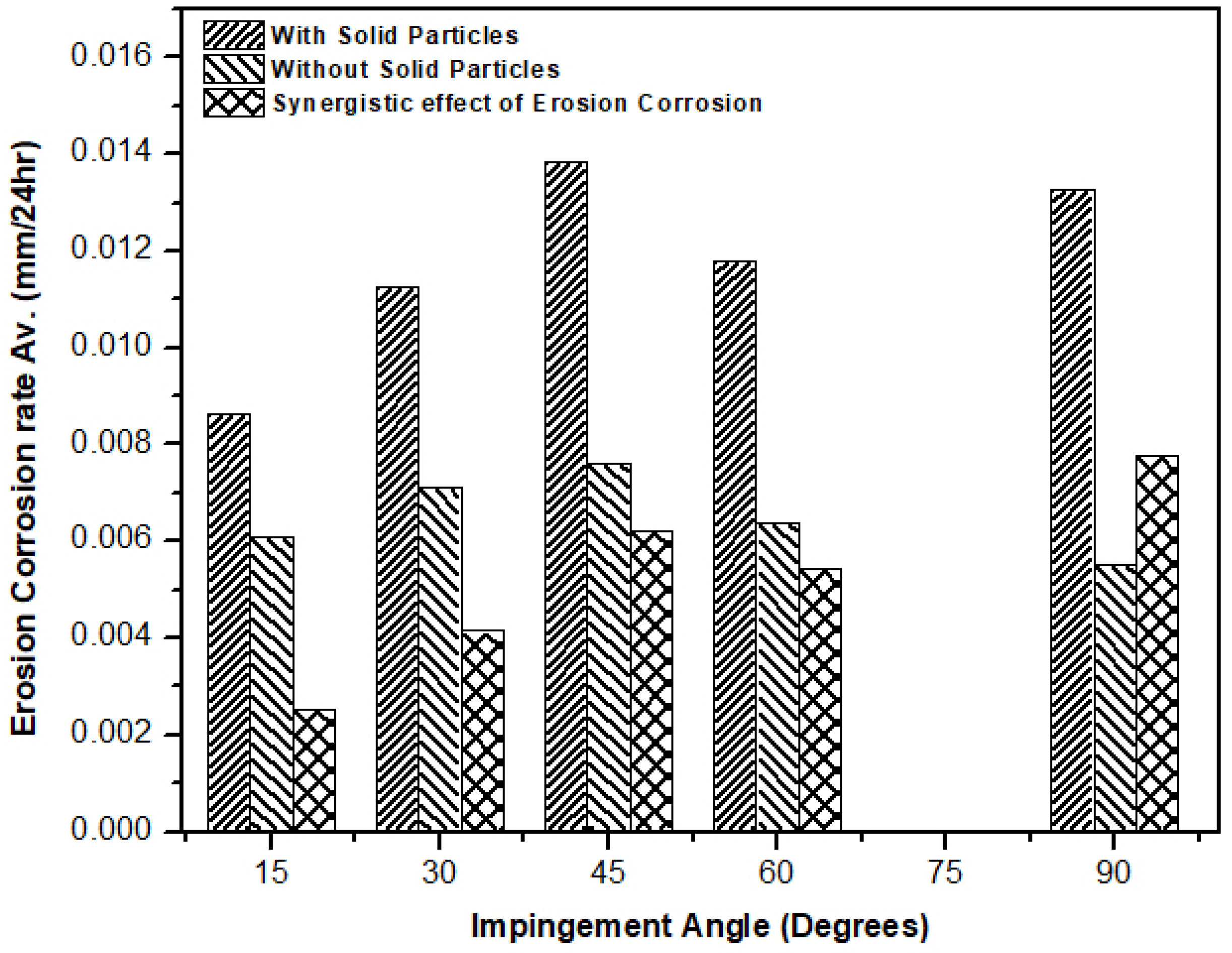
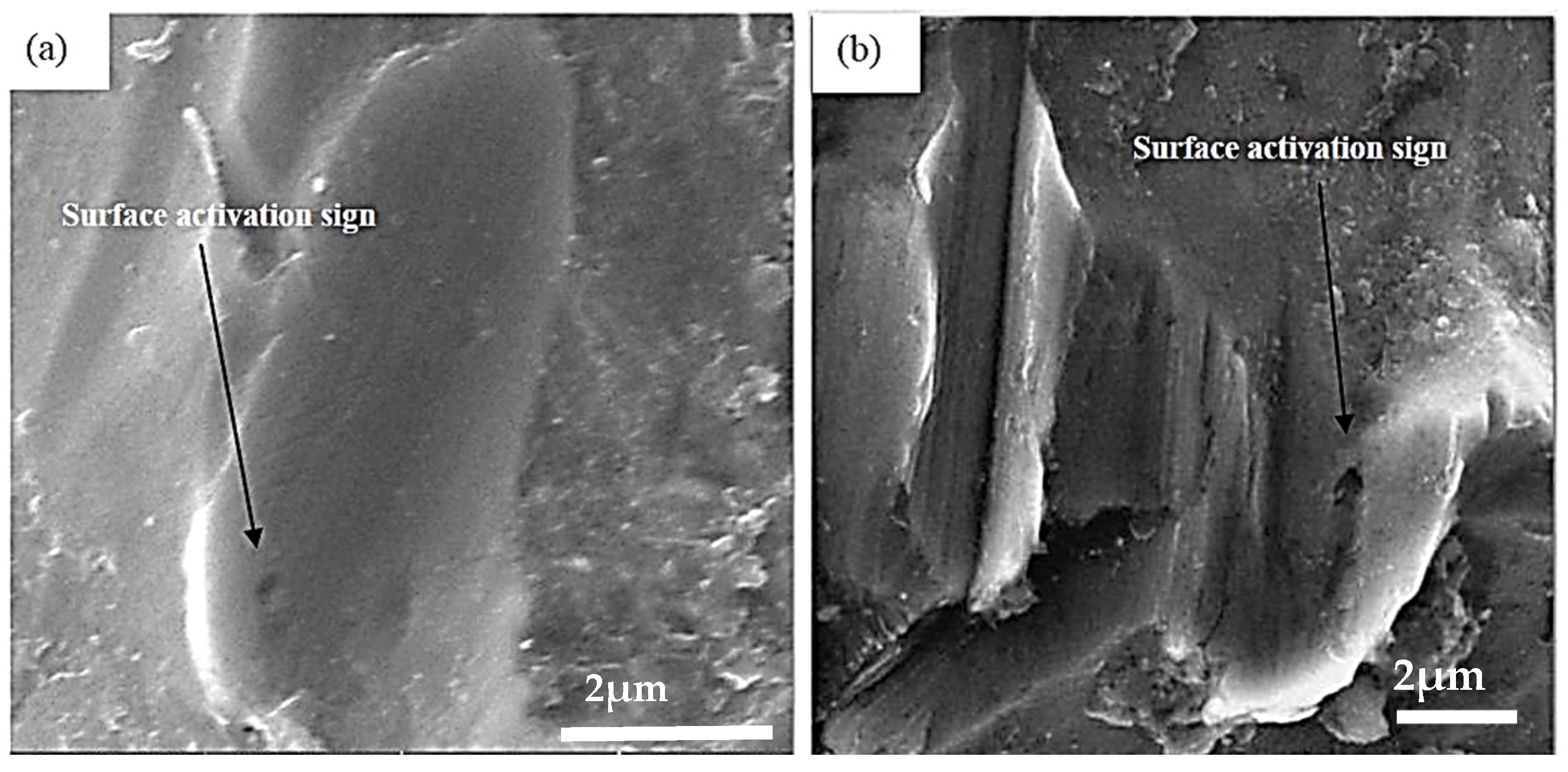
3.4. Effect of Erosion on Corrosion and Vice Versa

The corrosion process is controlled mainly by chemical and electrochemical action, while erosion is basically a mechanical wear process [33]. The combined effect of erosion and corrosion can be significantly much higher than the sum of the individual effects of both processes [18,31,33]. This increased combined effect is due to enhancement of erosion by corrosion and/or corrosion by erosion [18,31]. There is a plenty of literature discussing the erosion and corrosion mechanisms individually [34,35,36,37], however erosion–corrosion mechanism is not discussed in detail in order to understand the combined effect of erosion and corrosion. It is accepted that the impinging particles remove the deposits and protective layer from the metal surface and keep the underlying fresh metal exposed to corrosive environments, which ultimately increases the corrosion rate. It was proposed elsewhere [38] that erosion can affect the corrosion in different ways, such as by removing the surface deposits and increasing the local turbulence and roughening of the surface, and so it is reported that corrosion increases the erosion significantly [39,40]. Corrosion process can increase the surface roughness, which will increase the erosion rate as erosion is very sensitive to the impingement angle of impinging solid particles. The corrosion process can increase the erosion rate by removing the work hardened layer [39] and it is reported elsewhere [31] that corrosion can detach the flakes formed by repeated impacts of solid particles and thus increases the slurry erosion rate. Figure 12 shows that erosion–corrosion effect is very significant in terms of material loss at all impingement angles, however the combined effect at 45° and 90° angles was significant as compared to other angles. At 45°, particles penetrated much deeper in to the specimens due to the combined effect of shear and impact stresses, which increased the impingement erosion–corrosion as shown in Figure 13a,b. It was found that at 90°, due to extensive extrusion and fracture of platelets, erosion enhanced the corrosion significantly. The contribution to corrosion by erosion was obtained by subtracting the flow accelerated corrosion values (without sand particles) from total material loss observed during solid particle erosion–corrosion experiments. With the introduction of solid particles, surface roughness was increased and that accelerated the localized attack. There was a close relationship between contact force exerted by the particles on the surface and predicted material degradation rate as reported elsewhere [23,27].
Figure 12. The contribution of erosion to corrosion with the introduction of sand particles.
Figure 13. FE-SEM image shows surface activation and effect of erosion on corrosion; (a) 60° (b) 45°.
During an electrochemical corrosion process (without sand particles), an increase in fluid velocity will make it easier for the reacting species to quickly reach the metal surface and protecting corrosion products are easily removed [41]. It is reported by different researchers that the main reason behind this removed is an excessive presence of wall shear stresses between the fluid and metallic substrate/pipe etc. On the other hand, it is also reported that the removal of corrosion products from the metal surface is not dependent on shear, rather on a critical fluid velocity, above which corrosion rate will be significantly increased [42]. However, when the solid particles are present in the fluid, then an increase in fluid velocity will accelerate the erosive wear and protective films will be detached from the surface quickly. Subsequently, material degradation rate will be significantly increased [43,44].

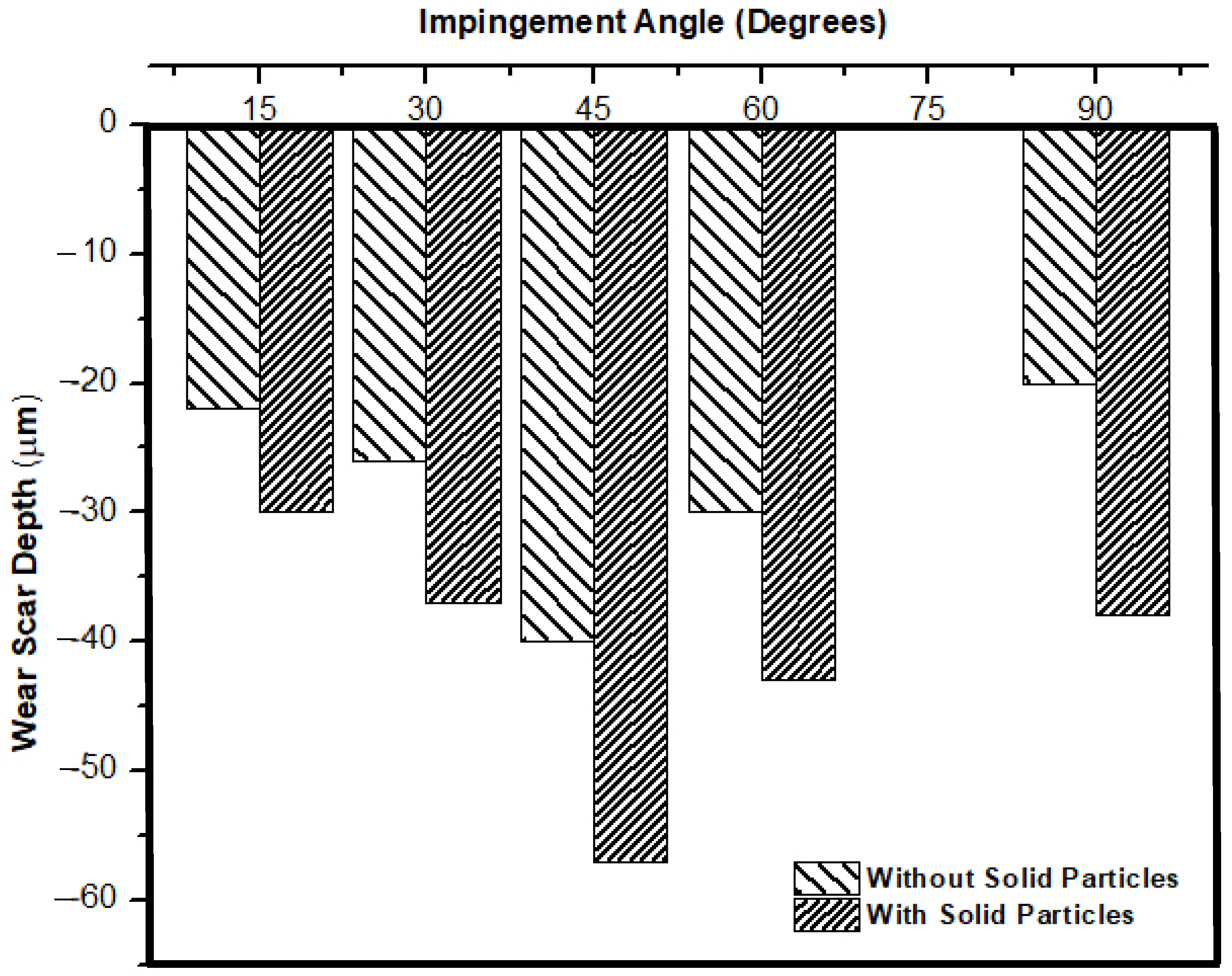
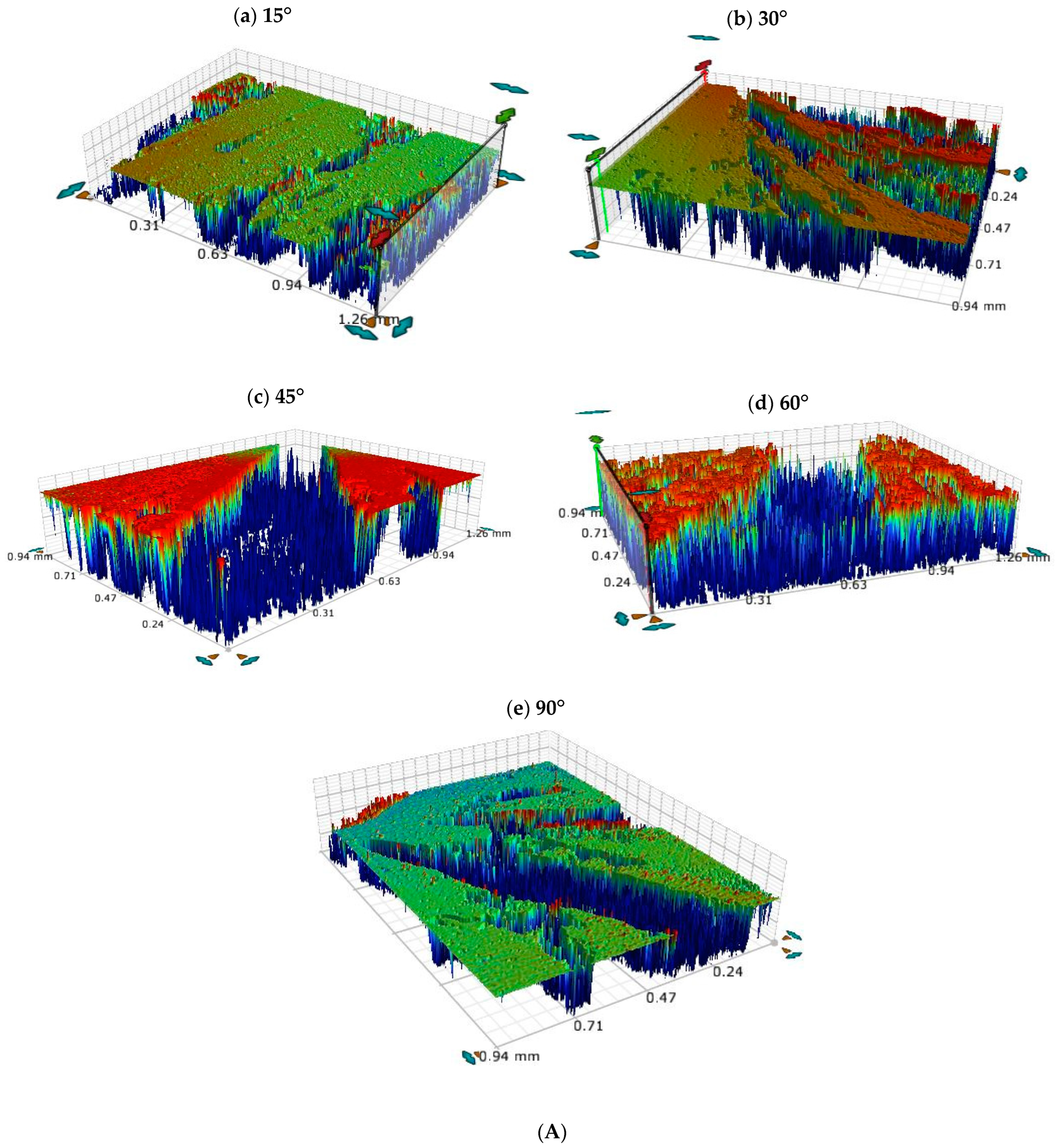
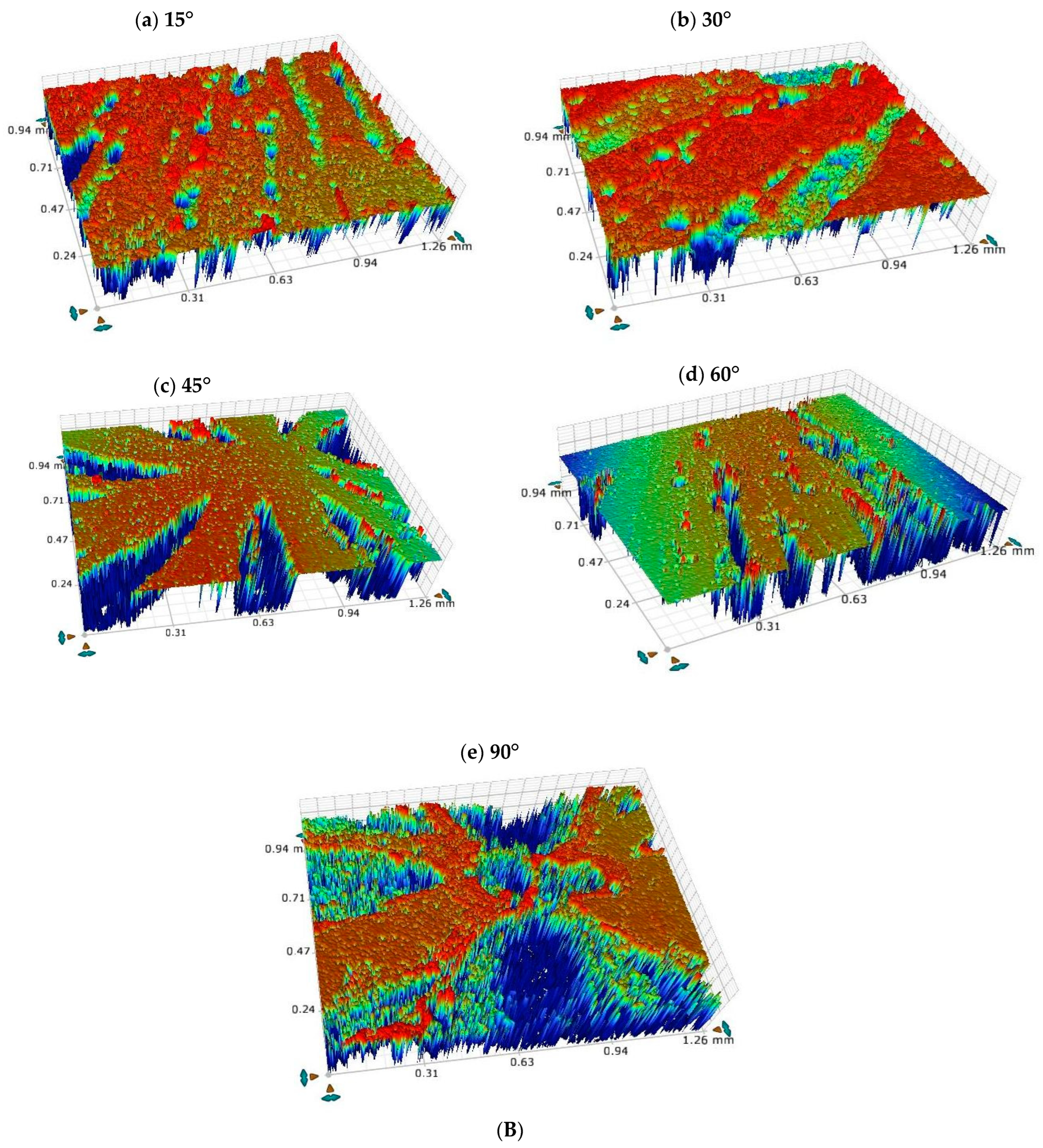
3.5. Optical Profilometric Studies of Corrosion/Wear Scars

Figure 8 showed that there were high velocity regions near the impingement point, and so it was expected that these regions will be highly affected by shearing and/or normal impact stresses. The maximum average depth of the corrosion/wear scars (at 12 m/s for 24 h in the range of 15°~90° and with/without solid particles) was examined using a GTK-A 3D optical profilometer. The effect of shear and impact stresses could be examined from 3D profiles of regions near the impingement points. During impingement corrosion (without solid particles), the penetration depth was found to be maximum at 45° (40 ± 5 µm), as shown in Figure 14.
Figure 14. Variation of corrosion wear scar penetration depths in µm during impingement and solid particle erosion–corrosion experiments at different angles.
This maximum material removal during impingement corrosion (Figure 15A) was because of the balance between the shear stress and normal stress [45,46]. The introduction of solid particles clearly ploughed deeper (as discussed in earlier sections) at intermediate angle, i.e., 45° degrees, giving a depth of 57 ± 5 µm. Whereas, at a 90° angle most of the particle’s kinetic energy was utilized in activating the surface by extrusion and to form the platelets, which were later fractured/removed by subsequent particle impact. This was clearly shown in Figure 15B, where the affected area at the impingement point was eroded and the recessed scar became much wider. Maximum depth at 90° angle was 38 ± 3 µm in the case of solid particle erosion–corrosion.
Figure 15. (A) 3D optical images at high velocity regions near the impingement points in the absence of solid particles. (B) 3D optical images at high velocity regions near impingement points in presence of solid particles.

4. Conclusions

This study investigated the impingement corrosion and erosion–corrosion behavior of AISI 1030 carbon steel under various test conditions, such as at five different impingement angles (15°, 30°, 45°, 60°, and 90°) and three different velocities (3 m/s, 6 m/s, and 12 m/s) at each angle, respectively. After the experiments, the specimen surface was examined by measuring the penetration depths of corrosive/wear scars. The results can be concluded as below.
  • Ploughing, elongated erosive tracks, and metal cutting were the dominating erosion–corrosion mechanisms at lower impingement angles, while extrusion, flattening of ridges, and fracture were dominant mechanisms at high impact angles.
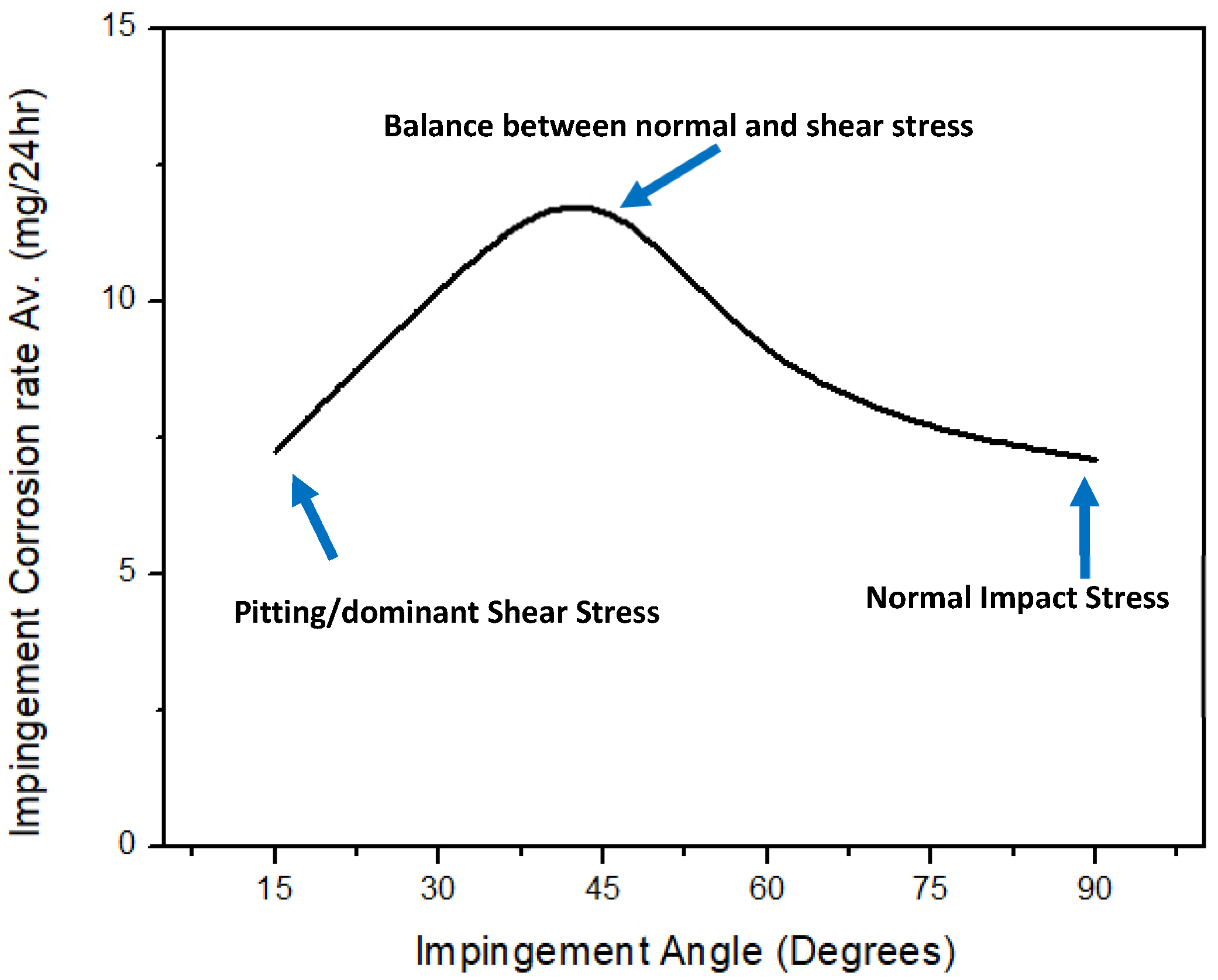
  • The increase in impingement corrosion and erosion–corrosion rates with an increase in impingement velocity was due to the presence of high shear and normal impact stresses. The maximum impingement corrosion and erosion–corrosion rates were found at a 45° impingement angle, as there was a balance between shearing force and normal impact force.
  • Erosion had a significant effect on corrosion as particles cut the surface and activate the localized sites, which resulted in accelerated corrosion attack.
  • The corrosion layer/oxide layer is continuously removed due to liquid jet impingement under high velocity conditions, as well as with the impact of the solid particles.

Author Contributions

Conceptualization: I.U.T. and H.M.B.; Methodology: I.U.T. and H.M.B.; Validation: I.U.T., H.M.B., H.M.I. and M.A.S.; Formal analysis: I.U.T. and H.M.I.; Investigation: I.U.T. and H.M.I.; Re-sources: I.U.T. and H.M.B.; Data curation: I.U.T. and H.M.I.; Writing—original draft preparation: H.M.I. and I.U.T.; Writing—review and editing: I.U.T. and H.M.I.; Visualization: I.U.T. and H.M.B.; Supervision: I.U.T.; Project administration: I.U.T.; Funding acquisition: I.U.T. All authors have read and agreed to the published version of the manuscript.

Funding

This research was funded by the Deanship of Scientific Research (DSR) at King Fahd University of Petroleum and Minerals (KFUPM) Saudi Arabia, under the research grant# IN171015.

Institutional Review Board Statement

Not applicable.

Data Availability Statement

Not applicable.

Acknowledgments

The authors gratefully acknowledge the support provided by King Fahd University of petroleum & Minerals (KFUPM) Saudi Arabia, under the research grant# IN171015 in conducting this research.

Conflicts of Interest

The authors declare no conflict of interest.

References

  1. Heidersbach, R. Metallurgy and Corrosion Control in Oil and Gas Production; John Wiley & Sons: Hoboken, NJ, USA, 2018. [Google Scholar]
  2. Levy, A.V. Solid Particle Erosion and Erosion-Corrosion of Materials; ASM International: Geauga County, OH, USA, 1995. [Google Scholar]
  3. Pasha, A.; Ghasemi, H.; Neshati, J. Synergistic Erosion–Corrosion Behavior of X-65 Carbon Steel at Various Impingement Angles. J. Tribol. 2017, 139, 011105. [Google Scholar] [CrossRef]
  4. Al Zoubi, W.; Kamil, M.P.; Fatimah, S.; Nashrah, N.; Ko, Y.G. Recent advances in hybrid organic-inorganic materials with spatial architecture for state-of-the-art applications. Prog. Mater. Sci. 2020, 112, 100663. [Google Scholar] [CrossRef]
  5. Al Zoubi, W.; Ko, Y.G. Chemical stability of synergistic inorganic materials for enhancing electrochemical performance. Compos. Sci. Technol. 2020, 199, 108383. [Google Scholar] [CrossRef]
  6. Javaherdashti, R.; Nwaoha, C.; Tan, H. Corrosion and Materials in the Oil and Gas Industries; CRC Press: Boca Raton, FL, USA, 2016. [Google Scholar]
  7. Neville, A.; Reyes, M.; Xu, H. Examining corrosion effects and corrosion/erosion interactions on metallic materials in aqueous slurries. Tribol. Int. 2002, 35, 643–650. [Google Scholar] [CrossRef]
  8. Verma, C.; Quraishi, M.; Rhee, K.Y. Aqueous Phase Polymeric Corrosion Inhibitors: Recent Advancements and Future Opportunities. J. Mol. Liq. 2021, 348, 118387. [Google Scholar] [CrossRef]
  9. Wang, J.; Shirazi, S.A. A CFD based correlation for mass transfer coefficient in elbows. Int. J. Heat Mass Transf. 2001, 9, 1817–1822. [Google Scholar] [CrossRef]
  10. Efird, K.D. Jet Impingement Testing for Accelerated Corrosion. In Corrosion 2000; NACE International: Houston, TX, USA, 2000; p. 00052. [Google Scholar]
  11. Fontana, M.G. Corrosion Engineering; McGraw-Hill Education: New York, NY, USA, 2005. [Google Scholar]
  12. Mazumder, Q.H. Prediction of erosion due to solid particle impact in single-phase and multiphase flows. J. Press. Vessel. Technol. 2007, 129, 576. [Google Scholar] [CrossRef]
  13. Giourntas, L.; Hodgkiess, T.; Galloway, A. Enhanced approach of assessing the corrosive wear of engineering materials under impingement. Wear 2015, 338, 155–163. [Google Scholar] [CrossRef] [Green Version]
  14. Khan, M.I.; Yasmin, T. Erosion–Corrosion of Low Carbon (AISI 1008 Steel) Ring Gasket Under Dynamic High Pressure CO2 Environment. J. Fail. Anal. Prev. 2014, 14, 537–548. [Google Scholar] [CrossRef]
  15. Sasaki, K.; Burstein, G. Erosion–corrosion of stainless steel under impingement by a fluid jet. Corros. Sci. 2007, 49, 92–102. [Google Scholar] [CrossRef]
  16. Neville, A.; Hodgkiess, T.; Xu, H. An electrochemical and microstructural assessment of erosion–corrosion of cast iron. Wear 1999, 233, 523–534. [Google Scholar] [CrossRef]
  17. Hu, X.; Neville, A. The effect of an impinging liquid-solid jet on the electrochemical corrosion of stainless steels. Mater. Corros. 2001, 52, 598–606. [Google Scholar] [CrossRef]
  18. Neville, A.; Hodgkiess, T.; Dallas, J. A study of the erosion-corrosion behaviour of engineering steels for marine pumping applications. Wear 1995, 186, 497–507. [Google Scholar] [CrossRef]
  19. Cui, Z.; Liu, Z.; Wang, L.; Li, X.; Du, C.; Wang, X. Effect of plastic deformation on the electrochemical and stress corrosion cracking behavior of X70 steel in near-neutral pH environment. Mater. Sci. Eng. A 2016, 677, 259–273. [Google Scholar] [CrossRef]
  20. Tian, H.; Wang, X.; Cui, Z.; Lu, Q.; Wang, L.; Lei, L.; Li, Y.; Zhang, D. Electrochemical corrosion, hydrogen permeation and stress corrosion cracking behavior of E690 steel in thiosulfate-containing artificial seawater. Corros. Sci. 2018, 144, 145–162. [Google Scholar] [CrossRef]
  21. Wang, L.; Liang, J.; Li, H.; Cheng, L.; Cui, Z. Quantitative study of the corrosion evolution and stress corrosion cracking of high strength aluminum alloys in solution and thin electrolyte layer containing Cl. Corros. Sci. 2021, 178, 109076. [Google Scholar] [CrossRef]
  22. Toor, I.U.; Alashwan, Z.; Badr, H.M.; Ben-Mansour, R.; Shirazi, S.A. Effect of Jet Impingement Velocity and Angle on CO2 Erosion–Corrosion with and without Sand for API 5L-X65 Carbon Steel. Materials 2020, 13, 2198. [Google Scholar] [CrossRef]
  23. Toor, I.U.; Irshad, H.M.; Badr, H.M.; Samad, M.A. The effect of impingement velocity and angle variation on the erosion corrosion performance of API 5L-X65 carbon steel in a flow loop. Metals 2018, 8, 402. [Google Scholar] [CrossRef] [Green Version]
  24. Abedini, M.; Ghasemi, H. Synergistic erosion–corrosion behavior of Al–brass alloy at various impingement angles. Wear 2014, 319, 49–55. [Google Scholar] [CrossRef]
  25. Liu, Y.; Zhao, Y.; Yao, J. Synergistic erosion–corrosion behavior of X80 pipeline steel at various impingement angles in two-phase flow impingement. Wear 2021, 466–467, 203572. [Google Scholar] [CrossRef]
  26. Azarian, N.S.; Ghasemi, H.M.; Monshi, M.R. Synergistic erosion and corrosion behavior of AA5052 aluminum alloy in 3.5 wt% NaCl solution under various impingement angles. J. Bio-Tribo-Corros. 2015, 1, 10. [Google Scholar] [CrossRef] [Green Version]
  27. Rajahram, S.; Harvey, T.; Wood, R. Evaluation of a semi-empirical model in predicting erosion–corrosion. Wear 2009, 267, 1883–1893. [Google Scholar] [CrossRef]
  28. Finnie, I. Erosion of surface by solid particles. Wear 1960, 3, 87–103. [Google Scholar] [CrossRef]
  29. Liang, G.; Peng, X.; Xu, L.; Cheng, Y.F. Erosion-corrosion of carbon steel pipes in oil sands slurry studied by weight-loss testing and CFD simulation. J. Mater. Eng. Perform. 2013, 22, 3043–3048. [Google Scholar] [CrossRef]
  30. Jingjun, L.; Yuzhen, L.; Xiaoyu, L. Numerical simulation for carbon steel flow-induced corrosion in high-velocity flow seawater. Anti-Corros. Methods Mater. 2008, 55, 66–72. [Google Scholar] [CrossRef]
  31. Burstein, G.; Sasaki, K. Effect of impact angle on the erosion–corrosion of 304L stainless steel. Wear 1995, 186, 80–94. [Google Scholar] [CrossRef]
  32. Islam, M.A.; Alam, T.; Farhat, Z.N.; Mohamed, A.; Alfantazi, A. Effect of microstructure on the erosion behavior of carbon steel. Wear 2015, 332, 1080–1089. [Google Scholar] [CrossRef]
  33. Neville, A.; Hodgkiess, T. Study of effect of liquid corrosivity in liquid-solid impingement on cast iron and austenitic stainless steel. Br. Corros. J. 1997, 32, 197–205. [Google Scholar] [CrossRef]
  34. Finnie, I. Some reflections on the past and future of erosion. Wear 1995, 186–187, 1–10. [Google Scholar] [CrossRef]
  35. Kermani, M.; Morshed, A. Carbon dioxide corrosion in oil and gas productiona compendium. Corrosion 2003, 59, NACE-03080659. [Google Scholar] [CrossRef]
  36. Meng, H.; Ludema, K. Wear models and predictive equations: Their form and content. Wear 1995, 181, 443–457. [Google Scholar] [CrossRef]
  37. Nesic, S.; Postlethwaite, J.; Olsen, S. An electrochemical model for prediction of corrosion of mild steel in aqueous carbon dioxide solutions. Corrosion 1996, 52, 280–294. [Google Scholar] [CrossRef]
  38. Zhou, S.; Stack, M.; Newman, R. Characterization of synergistic effects between erosion and corrosion in an aqueous environment using electrochemical techniques. Corrosion 1996, 52, 934–946. [Google Scholar] [CrossRef]
  39. Matsumura, M.; Oka, Y.; Hiura, H.; Yano, M. The role of passivating film in preventing slurry erosion-corrosion of austenitic stainless steel. ISIJ Int. 1991, 31, 168–176. [Google Scholar] [CrossRef] [Green Version]
  40. Postlethwaite, J. Effect of chromate inhibitor on the mechanical and electrochemical components of erosion-corrosion in aqueous slurries of sand. Corrosion 1981, 37, 1–5. [Google Scholar] [CrossRef]
  41. Li, W.; Pots, B.F.M.; Brown, B.; Kee, K.; Nesic, S. A direct measurement of wall shear stress in multiphase flow—Is it an important parameter in CO2 corrosion of carbon steel pipelines? Corros. Sci. 2016, 110, 35–45. [Google Scholar] [CrossRef]
  42. Gulbrandsen, E.; Grana, A. Testing of carbon dioxide corrosion inhibitor perfor-mance at high flow velocities in jet impingement geometry. Effects of mass transfer and flow forces. Corrosion 2007, 63, 1009–1020. [Google Scholar] [CrossRef]
  43. Hou, Y.; Aldrich, C.; Lepkova, K.; Kinsella, B. Detection of under deposit corrosion in a CO2 environment by using electrochemical noise and recurrence quantification analysis. Electrochim. Acta 2018, 274, 160–169. [Google Scholar] [CrossRef]
  44. Zheng, Z.B.; Zheng, Y.G.; Zhou, X.; He, S.Y.; Sun, W.H.; Wang, J.Q. Determination of the critical flow velocities for erosion-corrosion of passive materials under impingement by NaCl solution containing sand. Corros. Sci. 2014, 88, 187–196. [Google Scholar] [CrossRef]
  45. Ige, O.; Umoru, L. Effects of shear stress on the erosion-corrosion behaviour of X-65 carbon steel: A combined mass-loss and profilometry study. Tribol. Int. 2016, 94, 155–164. [Google Scholar] [CrossRef]
  46. Nguyen, Q.; Nguyen, V.; Lim, C.; Trinh, Q.; Sankaranarayanan, S.; Zhang, Y.; Gupta, M. Effect of impact angle and testing time on erosion of stainless steel at higher velocities. Wear 2014, 321, 87–93. [Google Scholar] [CrossRef]
Publisher’s Note: MDPI stays neutral with regard to jurisdictional claims in published maps and institutional affiliations.

Article Metrics

Citations

Article Access Statistics

Multiple requests from the same IP address are counted as one view.