Article

Application of User Side Energy Storage System for Power Quality Enhancement of Premium Power Park

Electric Power Research Institute of State Grid Hubei Electric Power Co., Ltd., Wuhan 430077, China
*
Author to whom correspondence should be addressed.
Sustainability 2022, 14(6), 3668; https://doi.org/10.3390/su14063668
Submission received: 26 January 2022 / Revised: 16 March 2022 / Accepted: 18 March 2022 / Published: 21 March 2022
(This article belongs to the Special Issue Advances in Energy Storage Systems: Design, Modeling and Applications)

Abstract

:
User-side battery energy storage systems (UESSs) are a rapidly developing form of energy storage system; however, very little attention is being paid to their application in the power quality enhancement of premium power parks, and their coordination with existing voltage sag mitigation devices. The potential of UESSs has not been fully exploited. Given the above, this paper proposes a hierarchical power supply strategy for premium power parks (PPPs) based on the coordination of UESSs and dynamic voltage restorers (DVR). Firstly, the topology and control strategy of the UESS for voltage sag mitigation are devised. Further, we construct a prototype device, and experimental tests are conducted to verify its effectiveness in voltage sag mitigation. To avoid the negative effects caused by the UESS control mode switching between the voltage sag mitigation mode and the peak-shaving and valley-filling modes—namely, the long control mode switching time and low state of charge (SOC)—a hierarchical power supply strategy is proposed. The basic idea is to supply three levels of power quality service for loads with different sensitivities in PPPs by coordinating UESS with DVR. Several cases are explored to demonstrate the feasibility of the proposed strategy.

1. Introduction

According to the application scenario, energy storage systems can be divided into three types: power generation-side energy storage systems, power grid-side energy storage systems, and user-side energy storage systems (UESS). Among them, the UESS was the first to be commercialized. A UESS is usually equipped behind the meter and is managed by users, and is usually a type of electrochemical energy storage system. In recent years, the UESS has been rapidly developed for its capabilities such as shifting peak loads, enabling demand-side response, and reducing electricity costs [1]. However, the large-scale application of UESSs is still restricted due to their high initial investment, low return, and long payback period. Therefore, to create greater economic benefits and promote the development of UESSs, it remains a necessity to explore more functions of the UESS.
In modern high-tech industrial enterprises, which are usually situated in industrial parks, increasingly advanced and precise equipment are being adopted in production lines, such as precision experimental devices, adjustable-speed drives, automatic production lines, and computer systems [2]. These devices are very sensitive and vulnerable to voltage sag, under which production disruptions probably occur, thereby causing huge economic losses [3,4]. It is reported that the annual loss to U.S. electricity consumers caused by voltage sag is as high as USD 26 billion [2]. Therefore, if UESS can be utilized for voltage sag mitigation in addition to peak-shaving and valley-filling in industrial parks, it will achieve more economic benefits.
Currently, there is a lot of research being done into power quality enhancement with energy storage systems (ESSs). (1) ESSs can be applied to mitigate voltage sag. The authors of [5] designed a voltage sag compensator using a flywheel energy storage system. In [6], the control of hybrid fuel cell (FC)/energy-storage distributed generation systems under voltage sag is studied. Based on superconducting magnetic energy storage, Zheng et al. proposed an MW-class dynamic voltage restorer (DVR) to mitigate voltage sag [7,8]. By combining BESSs and capacitor banks, the authors of [9] proposed a wattage and volt–amp reactive planning scheme to cope with the vulnerability of networks to voltage sag, and improve system efficiency. (2) ESSs can be utilized to improve the power quality of renewable energy integrated power systems [10]. To suppress sub-synchronous resonance (SSR) in power systems, Li et al. designed a synchronous compensator with a battery energy storage system [11], which is connected in parallel with the grid. In [12], a battery energy storage station and its control strategy were devised to reduce the output power fluctuation of a wind/photovoltaic hybrid power system. In [13], the authors proposed a supercapacitor ESS to alleviate the voltage flicker caused by wind power integration, thus improving the power quality of the distribution network. In [14], a BESS is integrated into a solar photovoltaic system to provide load compensation, harmonics mitigation, unity power factor, and an automated transition between different operation modes of the system. (3) ESSs can also enhance the power quality of microgrids. In [15], the BESS is used to improve the power quality of the microgrid, which can mitigate voltage fluctuations and harmonics simultaneously. A second-order sliding mode controller is proposed in [16] for the control of a hybrid energy storage system, which can improve and smooth the renewable resource’s intermittency, improve the quality of the injected power, and enable additional services such as voltage and frequency regulation. To accelerate the restoration of system voltage and frequency under a variety of disturbances, and thus improve the power quality of the microgrid, the authors of [17] propose a control strategy for a battery energy storage system (BESS) that is based on two intelligent decoupled controllers. The above research showed that ESS achieves an excellent performance in power quality enhancement.
However, all these studies use dedicated energy storage systems to achieve a certain goal, and did not consider the application of UESS in this regard, despite the potential of UESS. Nowadays, there is little research being done on UESS, and almost all of the existing research only focuses on the economic benefits of UESS brought about by peak–valley arbitrage [18,19,20,21,22,23], or the optimal configuration of UESS [24,25]. Given the above, the current applications of UESS have not fully exploited this system’s potential, and its economic benefits have not been maximized.
Motivated by the above consideration, this paper proposes a hierarchical power supply strategy by coordinating UESS with DVR for premium power parks (PPP). The main contributions of this paper are as follows:
(1)
The topology and control strategy of UESS for mitigating voltage sag are devised. Further, a prototype device is constructed and experimental tests are performed to verify the feasibility and effectiveness of the device;
(2)
A hierarchical power supply strategy is proposed innovatively to avoid the negative effect caused by the switching of the UESS control mode between voltage sag mitigation mode and peak-shaving and valley-filling mode. Consequently, three levels of power quality can be provided in the PPP. Simulations are conducted in PSCAD/EMTDC to prove the feasibility of the proposed strategy.
The remainder of this paper is organized as follows: in chapter 2, the basic topology of a typical PPP is introduced. The design of the topology and control strategy of the UESS for voltage sag mitigation is presented in chapter 3. Additionally, experimental tests are provided in this chapter. In chapter 4, the principle of the hierarchical power supply strategy based on the coordination of DVR and UESS is introduced. Chapter 5 shows the simulation results and chapter 6 concludes the paper.

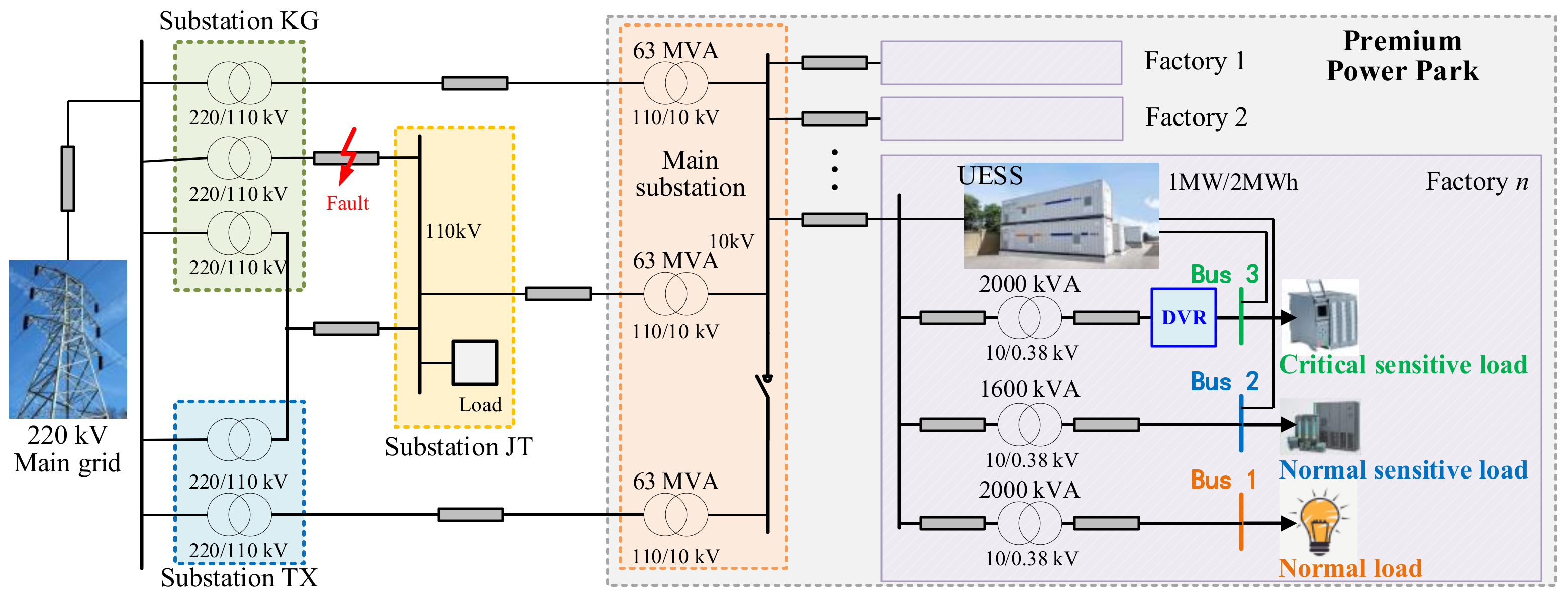
2. Basic Topology of the PPP

According to a field survey of an electronic enterprise in China, we designed a PPP with UESS to assist the research conducted in this paper, as shown in Figure 1. The PPP is supplied by two 220 kV substations and one 110 kV substation, i.e., a 220 kV substation KG, a 220 kV substation TX, and a 110 kV substation JT. In this PPP, the main substation contains three 110/10 kV 63 MVA transformers and supplies power to multiple factories. One of the factories is used as an example for further research, and the detailed topology is shown. As can be seen, there are three 380 V buses in factory n, namely, bus 1, bus 2 and bus 3. The capacity of the three distribution transformers is 2000 kVA, 1600 kVA, and 2000 kVA, respectively. The UESS is connected to and powered by the 10 kV bus, and the peak-shaving and valley-filling can be performed through this bus. Bus 2 and bus 3 are connected with the UESS for power quality enhancement. The DVR is connected in series between bus 3 and 10 kV bus to compensate for the voltage at the bus.
There are many types of equipment making different demands on the power quality in a PPP. When conducting voltage sag mitigation, it is helpful to classify these loads. Generally, the classification of sensitive equipment can be conducted based on two basic principles: (1) based on load sensitivity, the loads can be classified as extremely sensitive, normal sensitive, and common; (2) based on the level of loss, loads can then be classified as extremely important load, normal important load, and common load.
Table 1 illustrates the corresponding relation between three levels of power quality service (Q1, Q2, Q3) and three types of loads (L1, L2, L3) with different power quality requirements. The lowest level, Q1, provides for the power supply at bus 1, which is suitable for L1 sensitive loads with low voltage sag sensitivity, such as lighting load. The power quality of bus 2 is medium, Q2, which is suitable for an L2 sensitive load with medium voltage sag sensitivity, such as the load of the general production process. The highest level, Q3, is achieved at bus 3, which can support the access of L3 sensitive loads with high voltage sag sensitivity. L3 are usually critically sensitive loads, a crash in which could cause great financial loss.

3. Design and Control of UESS

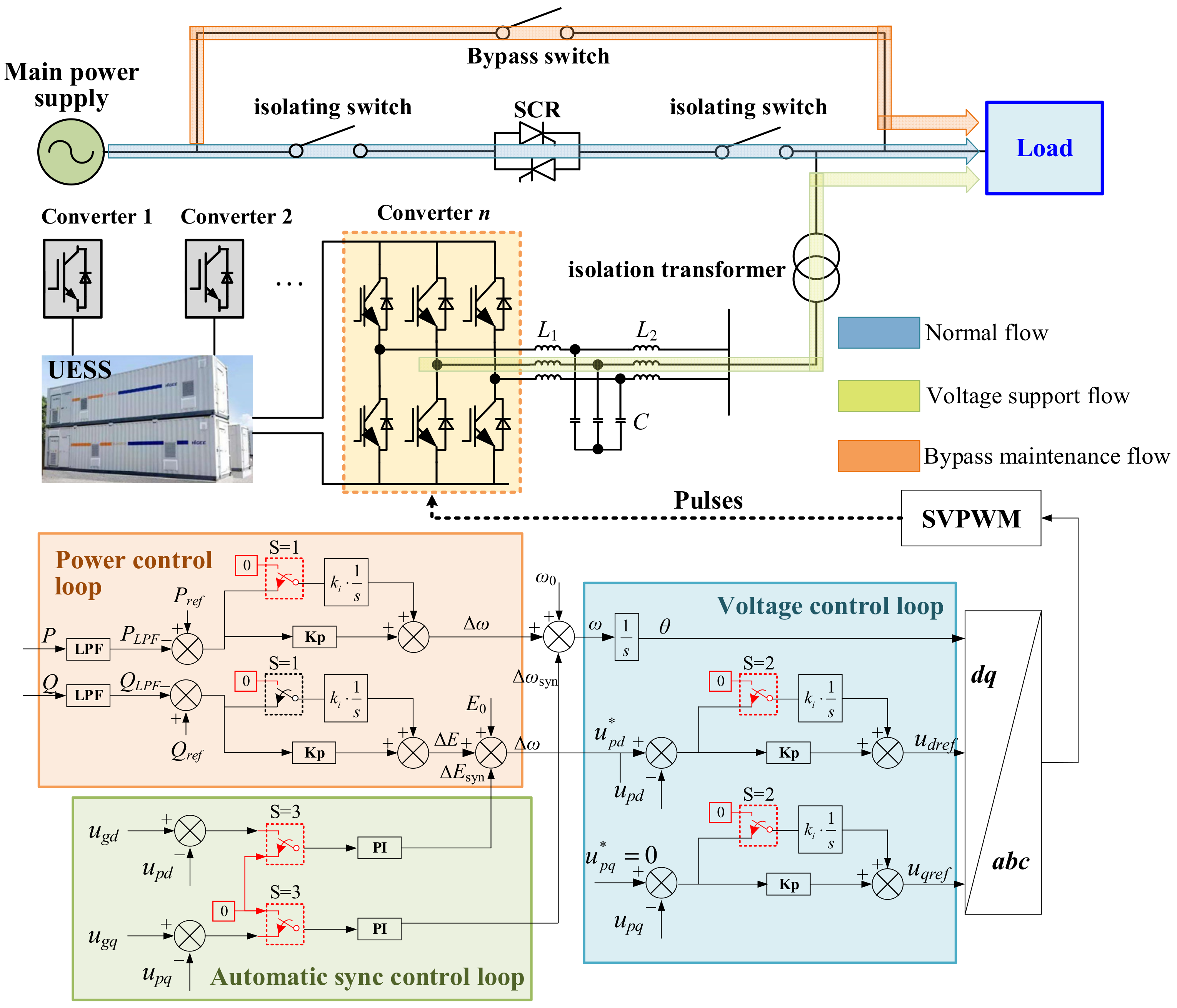
3.1. Topology and Control Strategy

To exploit new functions of UESSs in addition to peak-shaving and valley-filling, the topology and control strategy of UESS should be re-designed. The proposed basic topology and control strategy of UESS for voltage sag mitigation are shown in Figure 2. In addition to UESS, many other auxiliary components are added that work together to implement the voltage sag compensation function: bypass switches, isolating switches, thyristors, DC/AC converters, LCL filters, and isolation transformers. Notably, there can be multiple DC/AC converters for a single UESS, thus the UESS can support multiple sensitive loads spread throughout the factory at the same time.
There are three operation modes for the devised UESS. When the mains power is normal, the device is in a grid-connected mode. In this mode, the main power supply to the load and the energy storage converters are connected in parallel to the grid, and the device is in a standby or charging mode. In this mode, the peak-shaving and valley-filling function of the UESS can be performed. This is the sole operation mode of a traditional UESS.
When the voltage sag occurs, the UESS enters the voltage support mode. In this mode, the energy storage converter will replace the main supply and become the power source for sensitive loads. Differently from DVR, the UESS uses parallel compensation technology, so there is no need to design different control strategies for different types of voltage sags. When the voltage sag is over, the equipment is changed from the voltage support mode to the flexible exit mode. In this operation mode, the AC-side voltage of the energy storage converter is matched with the grid voltage. When the match is accomplished, the bidirectional thyristor is controlled and turned on, and the energy storage converter controls the output current of the energy storage device, making it slowly decrease to zero. Then, the device enters the grid-connected mode. Compared with the traditional UESS, these two operation modes are innovative additions.
For a regular energy storage converter, if the converter is switched improperly during control mode switching, overcurrent or overvoltage protection may occur, resulting in switching failure. Inspired by the control strategy of a virtual synchronous machine, we propose a control strategy suitable for a UESS in order to achieve the above functions and avoid the problems, as shown in Figure 2. The control strategy is mainly composed of three parts: the power control loop, the automatic synchronization control loop, and the voltage control loop. It realizes switching between the operation modes of the energy storage converter when mitigating the voltage sag.
As illustrated in Figure 2, PI controllers of the three control loops are enabled or disabled by the value of S; thus it can switch between the PI controller and the proportional controller, as represented by (1). S represents the operation mode of the UESS. S = 1 represents the grid-connected mode. At this time, the integral part of the PI controller of the power control loop will be enabled immediately, whilst the integral part of the other two PI controllers is disabled. Similarly, S = 2 and S = 3 represent the voltage support mode and the flexible exit mode, respectively.
u t = K p e t   +   K i e t d t K p e t
where e(t) and u(t) are the input and output of the controller, respectively. Kp and Ki are the proportion and integral coefficients, respectively.
In the voltage control loop, the active power and reactive power are calculated by
P = u p d i p d + u p q i p q       Q = u p d i p q + u p q i p d
where upd and upq are the d and q components of the output voltage of UESS, respectively. ipd and ipq are the d and q components of the output current of UESS, respectively. P and Q are the calculated active power and reactive power, respectively. Then, through low pass filters, by comparing with the reference active and reactive power Pref and Qref, PLPF and QLPF are used to control the converter.
If S = 3, then the automatic synchronization control loop will be activated. Error signals ΔEsyn and Δωsyn are generated to accelerate the synchronization.
In the voltage control loop, the rotor angle θ is calculated by
θ = ω 0 + Δ ω + Δ ω s y n d t
where ω0 is the initial value, and Δω and Δωsyn are the error signal generated by the power control loop and the automatic synchronization control loop, respectively.
The referent voltages are calculated by
U p d = E 0 + Δ E + Δ E s y n U p q = 0
where the superscript * represents the reference value, and ΔE and ΔEsyn are the error signal generated by the power control loop and the automatic synchronization control loop, respectively.

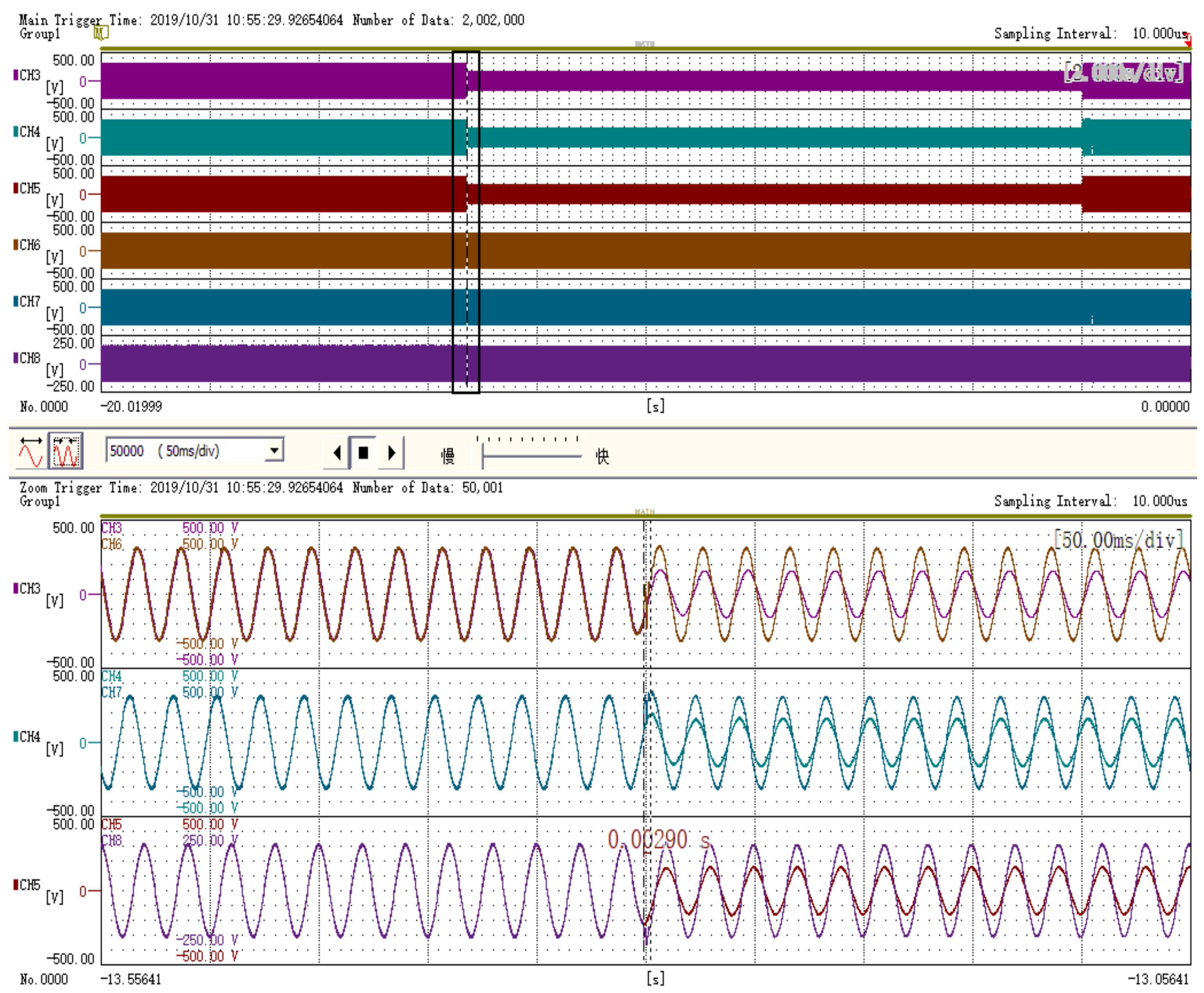
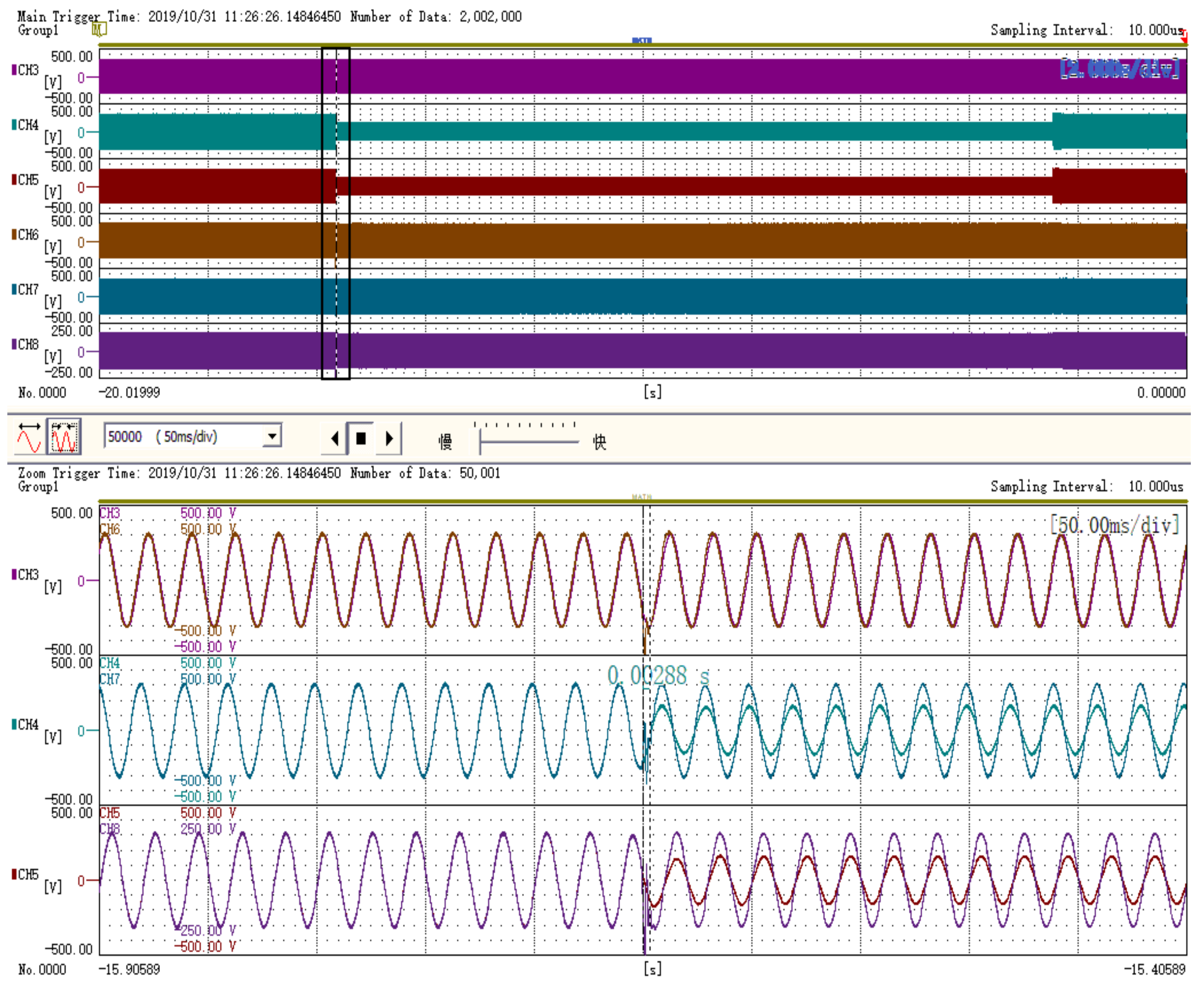
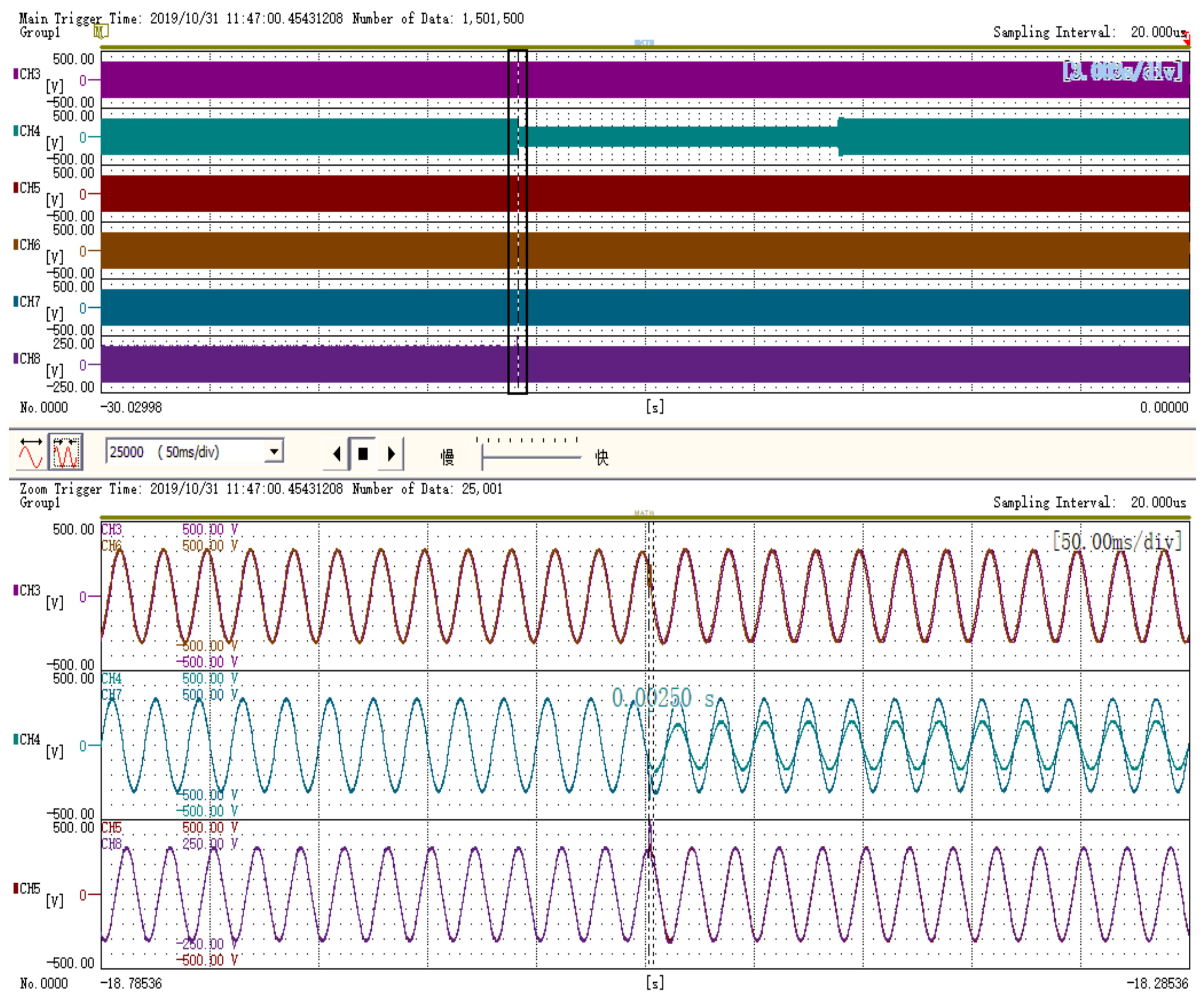
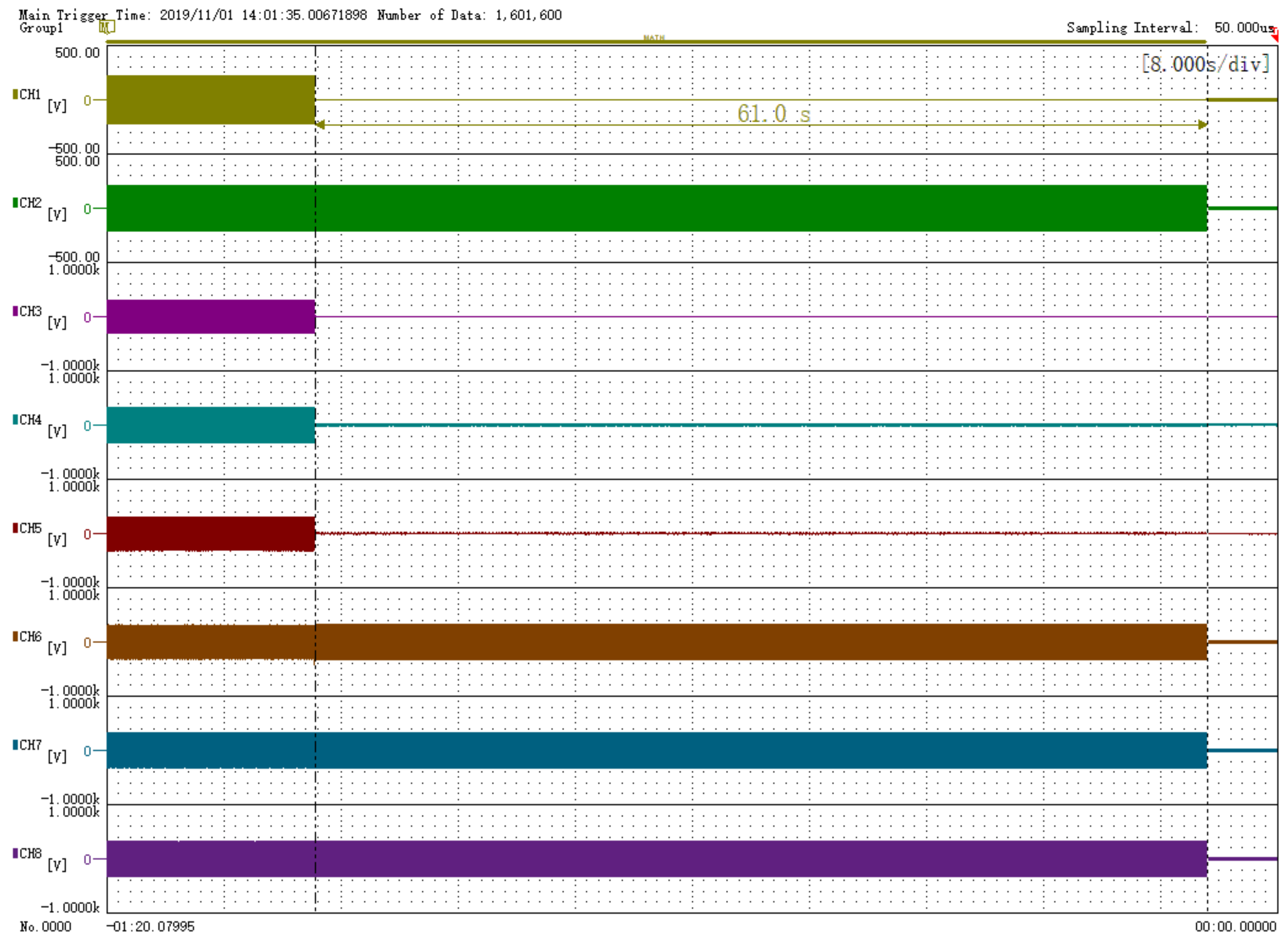
3.2. Experimental Tests

For further validating the feasibility of using UESS for voltage sag mitigation, a prototype of the ESS-based voltage sag mitigation device is constructed, and the main parameters are presented in Table 2. Here, we use the supercapacitor energy storage system to construct the prototype device. Four different cases are set to test the prototype device: (1) 0.5 p.u. three-phase voltage sag, (2) 0.5 p.u. two-phase voltage sag, (3) 0.5 p.u. single-phase voltage sag, and (4) voltage interruption.
(1)
Case 1: 0.5 p.u. three-phase voltage sag.
The test results under a 0.5 p.u. three-phase voltage sag are shown in Figure 3. Here, CH3 to CH5 in the upper half of the figure represent the input three-phase voltage, while CH6 to CH8 represent the output three-phase voltage. The zoomed-in area is shown in the bottom half of Figure 3. As can be seen, the device can compensate the output voltage to the normal state within 2.9 ms. During the entirety of voltage sag, the grid voltage is always 0.5 p.u., while the output voltage of UESS maintains a normal value.
(2)
Case 2: 0.5 p.u. two-phase voltage sag.
The test results under a 0.5 p.u. two-phase voltage sag are shown in Figure 4. As can be seen, the device can compensate for the output voltage to the normal state within 2.88 ms. The response time of this case is a little smaller than in case 1, since the voltage of phase A is normal. The UESS can also maintain the normal power supply of loads in this case.
(3)
Case 3: 0.5 p.u. single-phase voltage sag.
The test results under a 0.5 p.u. single-phase voltage sag are shown in Figure 5. As can be seen, the device can compensate for the output voltage to the normal state even faster than the first two cases, within 2.5 ms. The reason for this is that in this case, only phase B voltage drops. Likewise, the UESS can maintain the normal voltage of sensitive loads during the entire voltage sag in this case.
(4)
Case 4: voltage interruption.
The test results under a voltage interruption are shown in Figure 6. Here, CH1 and CH2 represent the input and output current, respectively. CH3 to CH8 have the same meaning as before. As can be seen, the input current and voltage drop to, and remain at, 0 at the same time. However, in the prototype device, the load voltage remains in the normal state up to 61 s.
The above experimental tests verify that the devised UESS-based device can protect sensitive loads from various voltage sags; the response time is less than 3 ms, and the support time is as long as 61 s. The performance is even better than DVR [7].

4. Principle of Hierarchical Power Supply Strategy

The experimental tests conducted in Section 3 verify that UESS performs excellently in voltage sag mitigation in a normal state. However, UESS alone cannot fully meet the power quality requirements of PPP, so it is necessary to coordinate the UESS with other voltage sag mitigation devices. The reason for this is two-fold. Firstly, the UESS in a PPP has multiple functions, such as peak-shaving and valley-filling, as well as voltage sag mitigation. All these functions will consume the energy stored in the UESS, and thus conflict between multiple operation modes is inevitable. For example, when voltage sag occurs at the time that the UESS is operating in a valley-filling state and the state of charge (SOC) is low, the UESS is not able to treat voltage sag well. In this condition, UESS may take a longer time to switch to voltage support mode, or the support time may become shorter. Secondly, there may be some already installed voltage sag mitigation devices in the PPP, such as a DVR. To avoid inefficiencies, in the application of UESS for voltage sag mitigation, we must take these devices into account.
To address the problem, we propose a hierarchical power supply strategy based on the coordination of DVR and UESS, as shown in Figure 7. First, Q1 (bus 1) is directly achieved by the main power supply without any compensation devices. Once faults occur, voltage sag will appear, and the normal power supply for L1 will be interrupted. Thus, Q1 has the lowest power quality level. On the contrary, due to the voltage enhancement of UESS, bus 2’s voltage can be maintained in most cases when the same faults occur. Therefore, Q2 (bus 2) has a higher power quality level compared with Q1. Finally, when UESS cannot treat voltage sag well due to emergencies (i.e., long control mode switching time or low SOC), the DVR will be put into operation, and will maintain the stability of bus 3’s voltage. Consequently, Q3 (bus 3) has the highest power quality level.

4.1. Lowest PQ Level

The basic principle of the lowest power quality level Q1 in the proposed supply strategy is shown in Figure 7. When the PPP is operated under a normal condition, the main power supply provides normal power supply for buses 1, 2, and 3 through mainline 1, thereby realizing the Q1 level for the load at bus 1. No compensation devices are connected in Q1. The Q1 level at bus 1 can only guarantee a normal power supply under the condition that mainline 1 operates normally, meaning the L1 load with low sensitivity to voltage sag can be accessed.

4.2. Medium PQ Level

Figure 7 illustrates the basic principle and diagram of the medium PQ level Q2, which is achieved by UESS. Under normal conditions in mainline 1, bus 2 is powered by the main power supply. When a fault occurs at mainline 1, UESS will be put into operation immediately after detecting the voltage sag. There are two possible results after the UESS is put into operation:
(1)
UESS can respond quickly and the SOC of UESS is high. In this case, the UESS can compensate for the load voltage completely for a long time. The voltage at bus 2 will be compensated to the reference value (rated voltage). The UESS will continue to run until its energy is used up or the voltage sag is over;
(2)
UESS cannot respond immediately, or the SOC of UESS is low. In this condition, loads at bus 2 will experience a voltage sag before the voltage is compensated (due to the long response time), or the voltage support only lasts for a short while (due to the low SOC). Thus, loads at bus 2 are still at risk of voltage sag in this condition.
With the help of UESS, the medium PQ level Q2 can be achieved, which can provide a normal power supply for sensitive loads under most conditions. Only when emergencies occur, i.e., the UESS is performing other functions and thus cannot respond to voltage sag immediately, or the SOC of UESS is low, the sensitive load cannot be supplied normally. Therefore, the Q2 level provides a higher power quality level than the Q1 level power supply, and is suitable for L2-type loads with moderate sensitivity to voltage sags.

4.3. Highest PQ Level

As shown in Figure 7, the idea of the Q3 level is to coordinate DVR and UBESS to provide a higher power quality level. The basic process is as follows:
  • Step 1—Under normal conditions, buses 1, 2, and 3 are powered by the main power supply;
  • Step 2—Under the condition of grid faults, when the Q2 level cannot ensure the normal power supply of bus 2 due to emergencies in the UESS, DVR will be put into operation after detecting the voltage sag at bus 3.
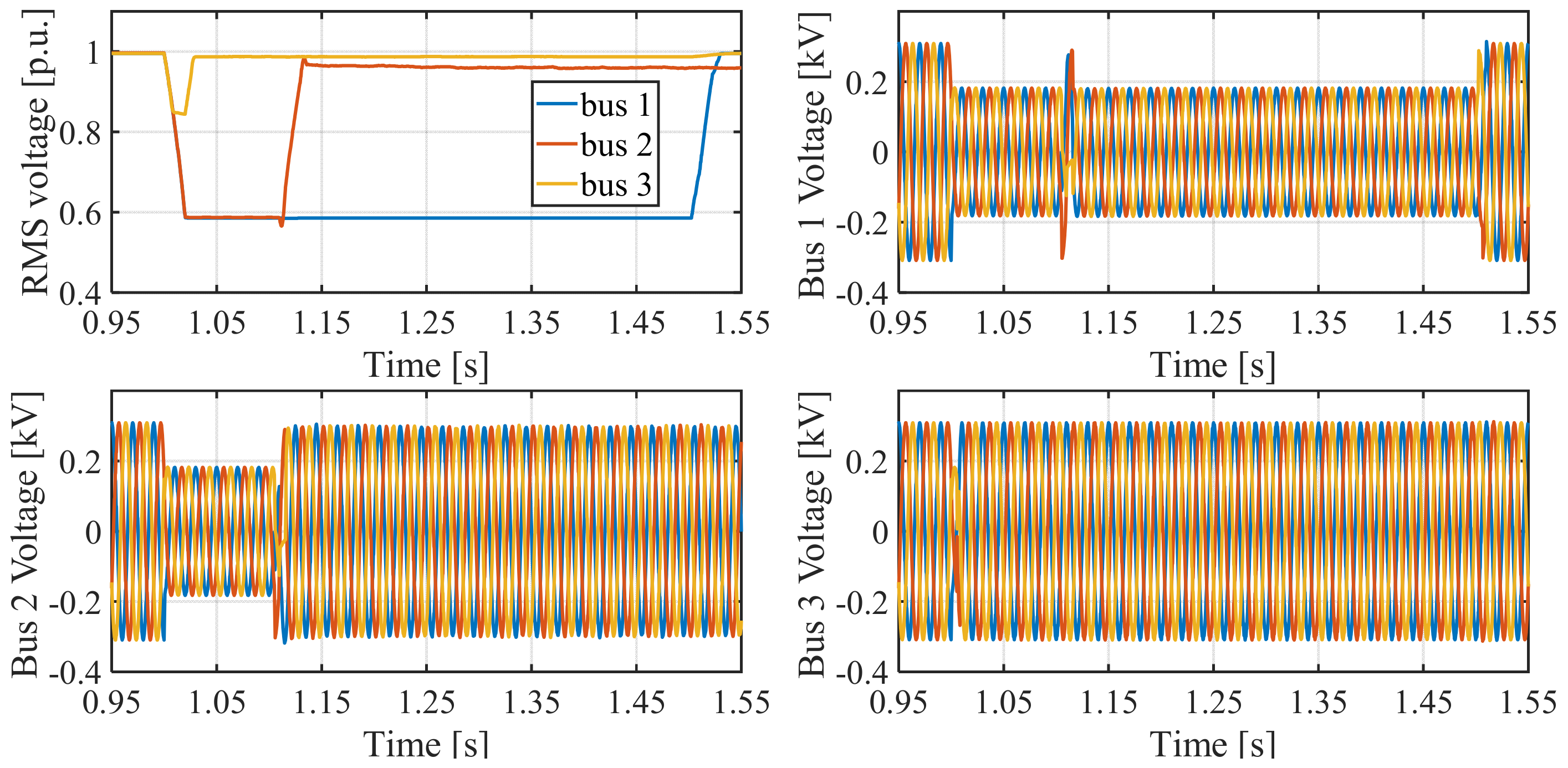
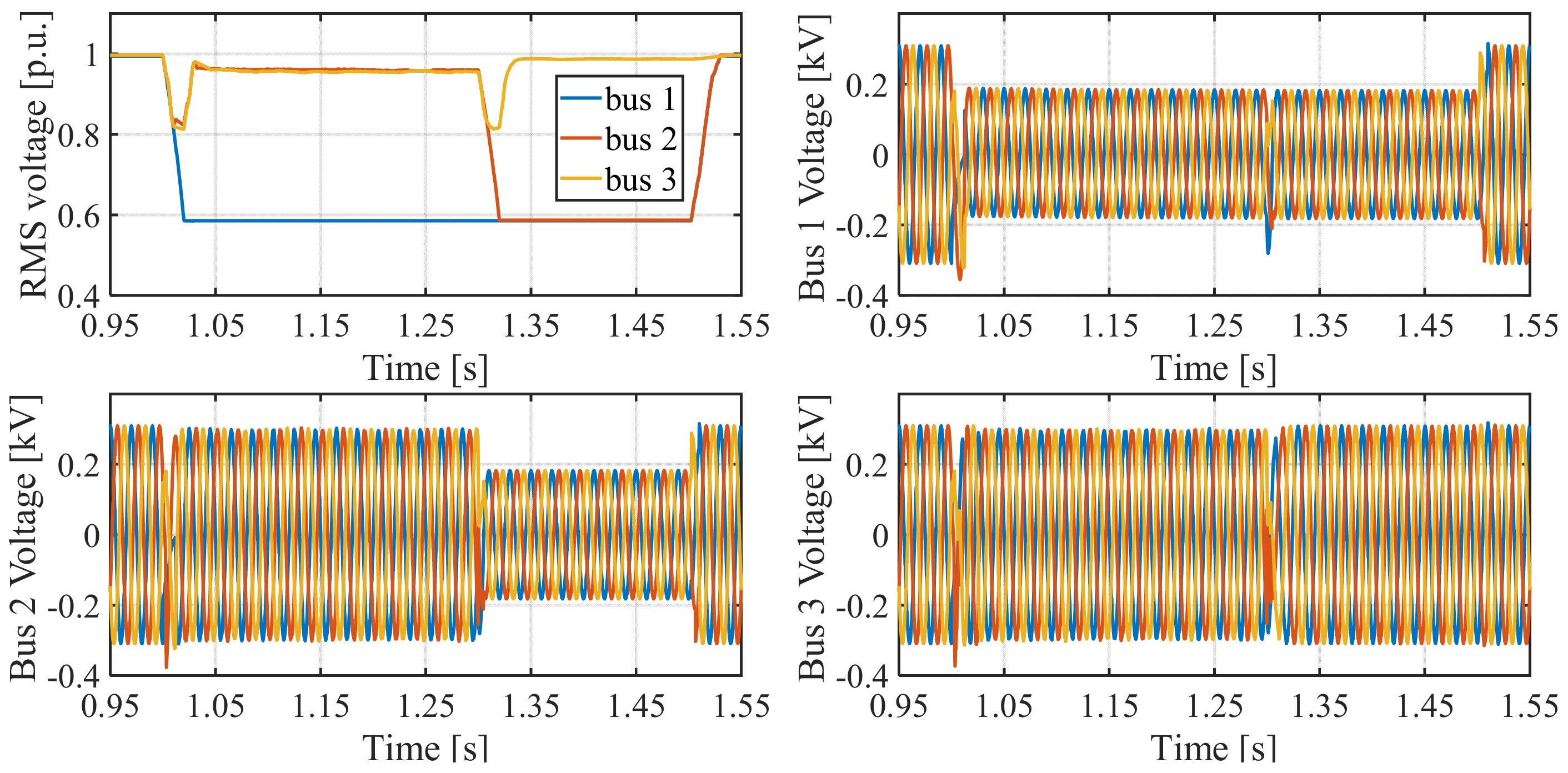
It can be seen that the Q3 level can normally supply the power for the sensitive load, based on the coordination of the UESS in a Q2 level service and the DVR, regardless of whether it is under normal conditions or grid fault conditions, and even when there are emergencies in the UESS. Therefore, the Q3 level provides a higher power quality level than Q1 and Q2, which is suitable for critical L3 loads with the highest sensitivity to voltage sag.

5. Case Study

To verify the effectiveness of the proposed strategy, a simulation model of PPP with UESS as shown in Figure 1 is built in PSCAD/EMTDC. For simplification, only one factory is constructed in the simulation model, and the parameters of the UESS are the same as those of the prototype device. The DVR is built according to [8], and loads are represented by a constant power load. Several cases are considered to simulate the proposed strategy, as follows:
(1)
Case 1—three faults occur at t = 1.0 s, with the duration of 500 ms. Besides this, the UESS operates normally;
(2)
Case 2—three faults occur at t = 1.0 s, with the duration of 500 ms. In addition, there is a 100 ms time delay in the control mode switching of the UESS;
(3)
Case 3—three faults occur at t = 1.0 s, with the duration of 500 ms. In addition, the UESS can only support loads with a duration of 300 ms due to the low SOC.

5.1. Under the Case of UESS Operating Normally

Figure 8 presents the voltage characteristics of different buses in the case of the UESS operating normally, i.e., case 1.
Figure 8 shows that when a grid fault occurs in the upper power grid, the voltage at bus 1 quickly drops at the moment the fault occurs. Subsequently, the UESS detects the voltage sag disturbance at bus 1, and quickly switches to the voltage support mode. Accordingly, the voltage at bus 2 is compensated for by the UESS to 0.96 p.u., and the voltage at bus 3 is also increased to near 1.0 p.u. As a result, due to the voltage compensation effect of UESS, the voltage values at bus 2 and bus 3 can still be maintained at an allowable level when voltage sag occurs, ensuring the normal operation of the sensitive load. In this case, the DVR is not activated, and only the UESS is compensating for the load voltages.
According to the simulation results, we can conclude that when operating normally, the UESS can effectively mitigate voltage sag, thus the Q2 service at bus 2 has a higher power quality level than the Q1 service at bus 1.

5.2. Under Cases of UESS Emergencies

When emergencies of UESS occur, the UESS cannot ensure the power quality of sensitive loads, e.g., cases 2 and 3 shown in Figure 9 and Figure 10.
The simulation results of case 2 are shown in Figure 9. According to Figure 9, we can see that the UESS cannot compensate for the load voltage until after a 100 ms delay. That is because the UESS is working in other modes, for example, the filling mode. It will thus take a longer time for the UESS to switch to the voltage mitigation mode. During this period, sensitive loads at bus 2 will still experience a voltage sag, and may be impacted by voltage sag. On the contrary, the voltage at bus 3 can be maintained at an acceptable level (0.98 p.u.) thanks to the DVR, and thus sensitive loads at bus 3 will not be impacted by voltage sag at all.
The simulation results for case 3 are shown in Figure 10. As can be seen, the voltage at bus 1 remains at 0.58 p.u. during the grid fault. With the help of the UESS, the voltage at bus 2 can be maintained at 0.96 p.u. for a while (300 ms), and it then drops to 0.58 p.u. due to the low SOC. The reason for this is that other operation modes consume too much energy, thus the SOC of the UESS is quite low when the voltage sag occurs. Differently from bus 2, the voltage at bus 3 can always be maintained within an allowable range thanks to the coordination of UESS and DVR; when the UESS is out of usage, the DVR will be put into operation, and thus the voltage at bus 3 can be compensated.
As a result, the simulation results in case 2 and case 3 demonstrate that when emergencies occur, the UESS cannot completely mitigate the voltage sag. For some extremely sensitive types of equipment, or some voltage sags with long duration, the UESS cannot protect sensitive equipment from voltage sag. Users in the PPP will still suffer financial losses from voltage sags. Conversely, owing to the coordination of the UESS and the DVR, the drawbacks of the UESS can be resolved and the voltage at bus 3 can be maintained within a permissible range. Therefore, the Q3 service at bus 3 has a higher power quality level than the Q2 service at bus 2 and the Q1 service at bus 1.

6. Conclusions

In this paper, we investigated the application of a UESS in voltage sag mitigation in a PPP. Firstly the topology design and control strategy of the UESS are presented. Experimental tests verify that under normal conditions, the UESS can mitigate the voltage sag quickly under various faults, with good performance. Then, to resolve the shortcomings of the sole UESS used in voltage sag mitigation, a hierarchical power supply strategy is proposed to achieve different levels of power quality service, based on the coordinated operation of the UESS and DVR. The lowest power quality level is directly supplied by the main power grid. The medium power quality level is obtained with the help of the UESS, while the highest power quality level is achieved by coordinating the UESS and the DVR. The research in this paper provides a feasible solution to realizing different levels of PQ service in industrial power parks, via the large-scale integration of a UBESS. The innovative work of this paper provides a new scheme to enable industrial entities to utilize UESS in ways besides peak-shaving and valley-filling, which can enable them to derive more economical benefits from UESS and promote the development of the UESS. In the future, we can develop more functions for UESSs, such as harmonic filtering and compensation for three-phase imbalances.

Author Contributions

Methodology, K.D., W.L.; validation, K.D., Y.Q.; writing, K.D., P.H.; funding acquisition, Z.H.; resources, K.D.; data curation, K.D. All authors have read and agreed to the published version of the manuscript.

Funding

This research was funded by the Science and Technology Project of State Grid Hubei Electric Power Company, grant number 52153221000N.

Institutional Review Board Statement

Not applicable.

Informed Consent Statement

Not applicable.

Data Availability Statement

The data are available upon request from the corresponding author.

Conflicts of Interest

The authors declare no conflict of interest.

References

  1. Yuan, B.; Wang, P.; Yang, J.; Xu, Z.; Zong, J. A review and outlook of user side energy storage development in China. In Proceedings of the 2019 IEEE 3rd International Electrical and Energy Conference (CIEEC), Beijing, China, 7–9 September 2019. [Google Scholar]
  2. Chen, Y.; Wang, Y.; Xiao, X.; Zheng, Z.; Zhang, H.; Wu, X. Improved premium model of voltage sag insurance based on voltage sag risk. IEEE Trans. Power Deliv. 2021, 1, to be published. [Google Scholar] [CrossRef]
  3. He, H.; Zhang, W.; Wang, Y.; Xiao, X. A sensitive industrial process model for financial losses assessment due to voltage sag and short interruptions. IEEE Trans. Power Deliv. 2021, 36, 1293–1301. [Google Scholar] [CrossRef]
  4. Sharma, A.; Rajpurohit, B.S.; Singh, S.N. A review on economics of power quality: Impact, assessment and mitigation. Renew. Sustain. Energy Rev. 2018, 88, 363–372. [Google Scholar] [CrossRef]
  5. Andrade, R.; Ferreira, A.; Sotelo, G. Voltage sags compensation using a superconducting flywheel energy storage system. IEEE Trans. Appl. Supercond. 2005, 15, 2265–2268. [Google Scholar] [CrossRef]
  6. Hajizadeh, A.; Golkar, M.A.; Feliachi, A. Voltage control and active power management of hybrid fuel-cell/energy-storage power conversion system under unbalanced voltage sag conditions. IEEE Trans. Energy Convers. 2010, 25, 1195–1208. [Google Scholar] [CrossRef]
  7. Zheng, Z.; Xiao, X.; Chen, X.; Huang, C.; Zhao, L.; Li, C. Performance evaluation of a MW-class SMES-BES DVR system for mitigation of voltage quality disturbances. IEEE Trans. Ind. Appl. 2018, 54, 3090–3099. [Google Scholar] [CrossRef]
  8. Zheng, Z.; Xiao, X.; Chen, X.; Huang, C.; Xu, J. Performance evaluation of a MW-class SMES-based DVR system for enhancing transient voltage quality by using d–q transform control. IEEE Trans. Appl. Supercond. 2018, 28, 5700805. [Google Scholar] [CrossRef]
  9. Islam, F.R.; Lallu, A.; Mamun, K.A.; Prakash, K.; Roy, N.K. Power Quality Improvement of Distribution Network Using BESS and Capacitor Bank. J. Mod. Power. Syst. Clean Energy 2021, 9, 625–632. [Google Scholar] [CrossRef]
  10. De Siqueira, L.M.S.; Peng, W. Control strategy to smooth wind power output using battery energy storage system: A review. J. Energy Storage 2021, 35, 102252. [Google Scholar] [CrossRef]
  11. Li, G.; Chen, Y.; Luo, A.; Wang, H. An Enhancing Grid Stiffness Control Strategy of STATCOM/BESS for Damping Sub-Synchronous Resonance in Wind Farm Connected to Weak Grid. IEEE Trans. Ind. Inform. 2020, 16, 5835–5845. [Google Scholar] [CrossRef]
  12. Li, X.; Hui, D.; Lai, X. Battery Energy Storage Station (BESS)-Based Smoothing Control of Photovoltaic (PV) and Wind Power Generation Fluctuations. IEEE Trans. Sustain. Energy 2013, 4, 464–473. [Google Scholar] [CrossRef]
  13. Ammar, M.; Joó, G. A Short-Term Energy Storage System for Voltage Quality Improvement in Distributed Wind Power. IEEE Trans. Energy Convers. 2014, 29, 997–1007. [Google Scholar] [CrossRef]
  14. Singh, Y.; Singh, B.; Mishra, S. Multifunctional Control for PV-Integrated Battery Energy Storage System with Improved Power Quality. IEEE Trans. Ind. Appl. 2020, 56, 6835–6845. [Google Scholar] [CrossRef]
  15. Ovaskainen, M.; Öörni, J.; Leinonen, A. Superposed control strategies of a BESS for power exchange and microgrid power quality improvement. In Proceedings of the 2019 IEEE International Conference on Environment and Electrical Engineering and 2019 IEEE Industrial and Commercial Power Systems Europe (EEEIC/I&CPS Europe), Genova, Italy, 11–14 June 2019. [Google Scholar]
  16. Tabart, Q.; Vechiu, I.; Etxeberria, A.; Bacha, S. Hybrid Energy Storage System Microgrids Integration for Power Quality Improvement Using Four-Leg Three-Level NPC Inverter and Second-Order Sliding Mode Control. IEEE Trans. Ind. Electron. 2018, 65, 424–435. [Google Scholar] [CrossRef]
  17. Alshehri, J.; Khalid, M. Power Quality Improvement in Microgrids Under Critical Disturbances Using an Intelligent Decoupled Control Strategy Based on Battery Energy Storage System. IEEE Access 2019, 7, 147314–147326. [Google Scholar] [CrossRef]
  18. Zhou, C.; Hu, Y.; Li, P.; Ma, X.; Lei, J.; Yuan, Z.; Yan, Z. Business model and economic analysis of user-side BESS in industrial parks in China. In Proceedings of the 8th Renewable Power Generation Conference (RPG 2019), Shanghai, China, 24–25 October 2019. [Google Scholar]
  19. Wu, N.; Xiao, J.; Feng, Y.; Bao, H.; Lin, R.; Chen, W. Economic feasibility analysis of user-side battery energy storage based on three electricity price policies. In Proceedings of the 2020 IEEE Sustainable Power and Energy Conference (iSPEC), Chengdu, China, 23–25 November 2020. [Google Scholar]
  20. Zhang, H.; Kang, L.; Cai, J. Optimal configuration of user-side energy storage considering load response and demand management. In Proceedings of the 2021 IEEE 4th International Conference on Electronics Technology (ICET), Chengdu, China, 7–10 May 2021. [Google Scholar]
  21. Mu, Q.; Gao, Y.; Yang, Y.; Liang, H. Design of power supply package for electricity sales companies considering user side energy storage configuration. Energies 2019, 12, 3219. [Google Scholar] [CrossRef] [Green Version]
  22. Hong, L.; Li, Y.; Ding, N.; Rizwan, M. Optimal capacity allocation strategy and economic analysis of grid side-user side energy storage system based on cooperative game. In Proceedings of the 2019 IEEE Sustainable Power and Energy Conference (iSPEC), Beijing, China, 21–23 November 2019. [Google Scholar]
  23. Dai, B.; Ye, L.; Li, Y.; Wang, C.; Shi, Z.; Li, Q. Economic analysis of user-side electrochemical energy storage considering time-of-use electricity price. In Proceedings of the 2021 3rd Asia Energy and Electrical Engineering Symposium (AEEES), Chengdu, China, 26–29 March 2021. [Google Scholar]
  24. Zhao, Y.T.; Wang, H.F.; He, B.T.; Xu, W.N. Optimization strategy of configuration and operation for user-side battery energy storage. Autom. Electr. Power Syst. 2020, 44, 121–128. [Google Scholar]
  25. Deng, T.; Tian, L.; Ge, W.; Liu, X.; Luo, H.; Zhou, G. Configuration evaluation and operation optimization model of energy storage in different typical user-side. Power Syst. Technol. 2020, 44, 4245–4253. [Google Scholar]
Figure 1. The simplified topology of an actual PPP integrated with UESS.
Sustainability 14 03668 g001
Figure 2. Working principle of UBESS.
Sustainability 14 03668 g002
Figure 3. Experimental test results under a 0.5 p.u. three-phase voltage sag.
Sustainability 14 03668 g003
Figure 4. Experimental test results under a 0.5 p.u. two-phase voltage sag.
Sustainability 14 03668 g004
Figure 5. Experimental test results under a 0.5 p.u. single-phase voltage sag.
Sustainability 14 03668 g005
Figure 6. Experimental test results under voltage interruption.
Sustainability 14 03668 g006
Figure 7. Flow diagram of hierarchical power supply strategy.
Sustainability 14 03668 g007
Figure 8. Simulation results under case 1.
Sustainability 14 03668 g008
Figure 9. Simulation results under case 2.
Sustainability 14 03668 g009
Figure 10. Simulation results under case 3.
Sustainability 14 03668 g010
Table 1. Classification of loads and power quality.
Load TypeSensitivityPQ Level
L1LowQ1
L2MediumQ2
L3HighQ3
Table 2. Parameters of the prototype device.
ParameterValueParameterValue
Rated capacity200 kVATotal harmonic distortion≤3%
Rated voltage380 VSwitch frequency10 kHz
Rated frequency50 Hz ± 5%Mode of connection3 phase 4 wire
Rated DC voltage765 VPower factor0.99
LCL filter (L1, L2, C)100 μH, 30 μH, 60 μF, Transformer50 kW, 400 V/400 V
Publisher’s Note: MDPI stays neutral with regard to jurisdictional claims in published maps and institutional affiliations.

