Article

Simulation of Leakage Characteristics of Combined Seal Structure under Rotational Conditions

1
Department of Hydraulic Engineering, College of Civil Engineering, Tongji University, Shanghai 200092, China
2
Shanghai Urban Construction Design and Research Institute (Group) Co., Ltd., Shanghai 200125, China
3
School of Chemistry and Chemical Engineering, Shanghai Jiao Tong University, Shanghai 200240, China
*
Authors to whom correspondence should be addressed.
Sustainability 2022, 14(6), 3648; https://doi.org/10.3390/su14063648
Submission received: 3 March 2022 / Revised: 14 March 2022 / Accepted: 18 March 2022 / Published: 20 March 2022

Abstract

:
In order to reduce fluid leakage and improve the working efficiency of rotational machinery, a three-dimensional (3D) model of combined seal structure (CSS) was established to study the influence of pressure ratio (π, the ratio of the leakage port pressure to the outlet pressure) and rotational speed (n) on the leakage characteristics of CSS with a traditional labyrinth seal structure (LSS) and pocket damping seal structure (PDS) under rotational conditions. Two turbulence models, the standard k-ε model and the SST k-ω model, were used for turbulence closure and the results of the standard k-ε model were found to be more accurate based on comparison with experimental results. The results revealed that under rotational condition, the leakage rates of LSS, CSS and PDS all decreased with the increase in π and n. Under the same axial length of seal structure and π of 0.5 and n of 6000 r/min, the leakage rate of CSS is approximately 8.56% less than LSS, and approximately 0.51% more than PDS. There is a critical value for the influence of n on the leakage rate. The critical n of CSS is close to that of LSS, about 1000 r/min, which is greater than the critical n of 500 r/min for PDS. Finally, the sealing mechanism of CSS was studied using a two-dimensional (2D) model, and was found that the jet structure has a greater influence on the sealing characteristics. Among them, when the ΔP (internal resistance of the device) is the same, the shape of the jet structure, the position of the guide tube and the nozzle radius have a greater impact on the leakage rate, and the shape and length of the extended section have a small effect on the leakage rate.

1. Introduction

As the use of rotational machinery develops towards high temperature, high pressure and high speed, correspondingly higher requirements have been put forward on the seal structure whose leakage characteristics will directly affect the working efficiency of the rotational machinery [1]. As an example, with the upgrading of power system requirements, high-temperature superconducting motors with high efficiency, high power density, low noise of vibration and good overload capacity have emerged. Since the high-temperature superconducting motor generates an army of heat in the course of operation, the cooling system has an important influence on the efficiency of the motor. The seal structure, as a part of the cooling system, is essential to the successful operation of the high-temperature superconducting motor [2,3]. In the dynamic-static coupling device of rotational machinery, the fundamental goal of annular seals is to control the flow of fluid from the high-pressure zone to the low-pressure zone through the gap between the stator and the rotor in order to effectively reduce leakage and improve the aerodynamic efficiency of the rotational machine. Being a kind of annular seal, LSS is widely used in cooling systems, rotational packed beds, compressors, and other rotational machinery due to its simple structure and stable performance to throttle and reduce losses [4,5,6,7,8]. However, under the condition of higher pressure, the sealing performance of LSS is unsatisfactory, which results in a large loss of efficiency of the rotational machinery. Therefore, how to promote the sealing performance of LSS, reduce its leakage, and improve the working efficiency of rotational machinery has become an urgent issue to be solved.
At present, a number of experts have proposed many different improvements for LSS, such as high and low tooth labyrinth seal structure, step labyrinth seal structure, staggered labyrinth seal structure, T-shaped seal structure and PDS, and these structures have achieved favorable results in practical applications [9,10,11,12,13,14,15,16]. As an example, Szymanski et al. [17] put forward four configurations of labyrinth through seals: smooth platform, honeycomb platform, extruded honeycomb and diamond platform, and used experimental methods to study the labyrinth reference geometry and optimized geometry. Sankaranaryanasamy et al. [18] defined a semi-empirical model that used neural network technology for data recognition and optimized the size of the sealed cavity. Li et al. [19,20] had optimized the structure of LSS, and compared the sealing performance of optimized T-shaped seal and staggered labyrinth seal with a straight-through labyrinth seal. When the axial length and the sealing gap of seal structure were in the same dimension, the leakage of the T-shaped seal was 23.6–25.3% less than that of the straight-through labyrinth seal, and approximately 7.4–8.5% more than the staggered labyrinth seal. Kim and Cha [21] proposed that when the sealing gap was minor, the leakage characteristics of stepped seals were similar to straight-through seals, but as the gap became larger, the advantages of stepped seals would gradually become apparent. In 1991, Vance and Schultz [22] first invented and tested PDS, which used partition walls to equally separate the gaps between the stator and the rotor. The structure has been widely studied since it can effectively address the issue of rotor instability in rotational machinery. In comparison with LSS, PDS has considerable direct damping (approximately 100 times that of LSS), which can effectively reduce rotor vibration effects [23]. However, the disadvantages (static instability is easy to occur, and the processing is complex) of PDS are also evident, so it cannot be widely used in practical applications [24]. In addition to the research on the improvement of structure of LSS, a large number of researchers have also conducted research on parameters (rotational speed, pressure ratio, etc.) that affect the leakage of LSS. Waschka et al. [25] found that the effect of speed could be ignored at low rotational speeds, since the leakage rate remained essentially unchanged as the speed increased. Given that, Nayak [26] studied the rotational effects of smooth and honeycomb cells at different seal gaps and speeds. The study revealed that as the speed increased, the seal emission coefficient remained constant until the critical speed was reached. Yahya et al. [27] analyzed the influence of rotor speed on the distribution of flow and leakage of LSS, and interpreted the phenomenon that rotation of the rotor would accelerate the wear of the tooth tip. Pressure ratio is another vital factor that affects leakage in annual seals. One study found that an increase in the pressure ratio in annual seals would lead to a decrease in leakage [28]. Li et al. [29] further studied the influence of the pressure ratio on the leakage characteristics of the improved annual seal structure (PDS), and the results showed that the leakage flow increased with the decrease in the pressure ratio under the condition of constant inlet pressure.
The majority of the above studies have adopted theoretical and experimental methods to optimize the structure and parameters of annual seals. In addition to these two methods, numerical simulation is a new research method and a powerful tool, and has also been widely used in the research of annual seals. As an example, Bondarenko et al. [30] analyzed the leakage of LSS with rotational speed under different pressure ratios through experiments and numerical simulations, and modified the calculation formula. Kong et al. [31] studied the internal flow field of the high and low tooth labyrinth seal through numerical simulation, compared the leakage characteristics of the seal under different pressure ratios and speeds, and verified the results through experiments.
In the previous work, a new type of combined sealing structure (CSS) consisting of a nozzle structure and a labyrinth structure to improve the sealing effect under non-rotating conditions was proposed, and the numerical model was verified through experimental results [32]. From this perspective, this study used numerical simulation to study the influence of pressure ratio and speed on the leakage characteristics of CSS, and compared it with LSS and PDS to evaluate the sealing characteristics under rotational conditions. In addition, the influencing factors such as jet structure shape, extended section, position of guide tube and nozzle radius were discussed in detail to reveal its sealing mechanism.
2. Numerical Methods

2.1. Physical Models

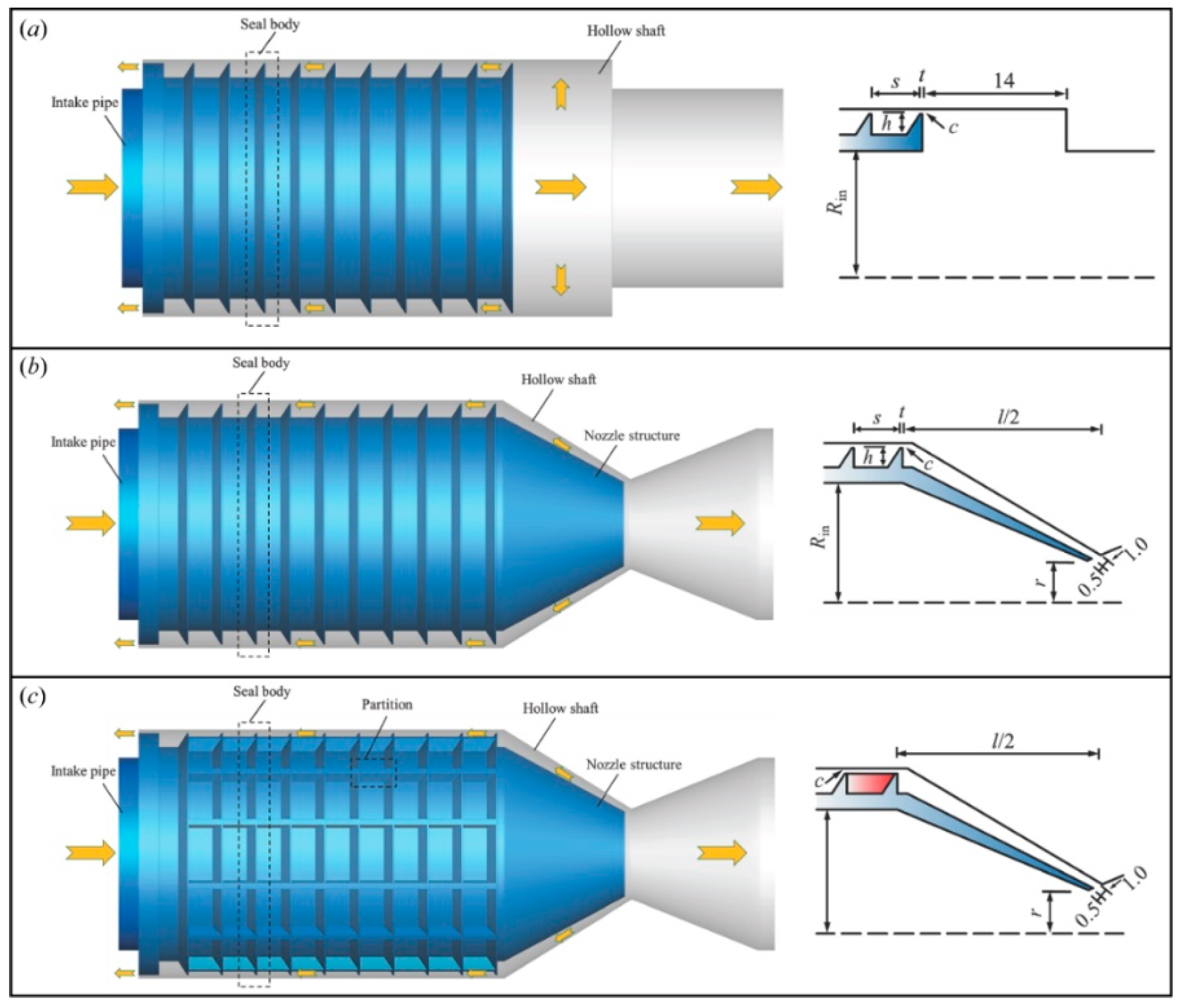
Figure 1 shows the physical models of LSS, CSS and PDS used for rotational machinery with hollow shaft. The key parameters of the model are shown in Table 1. The sealing structure includes rotational and stationary parts. Among them, the stationary part is a hollow shaft, and the rotational part includes an air inlet pipe, an air outlet pipe and a sealing element. The sealing element, composed of sealing teeth arranged circumferentially, is annular and fixed on the outer surface of the intake pipe. The hollow shaft is arranged outside the sealing body to form a sealing gap which is separated by sealing teeth to form a sealed cavity with the sealing body. The majority of the fluid passes through the main flow channel of the intake pipe and is discharged through the outlet, with a small part of the fluid leaking through the gap between the sealing body and the hollow shaft and being discharged from the leakage port. As shown in Figure 1b, CSS consists of an annular seal and a nozzle structure connected by an inclined gap. The minimum width of the inclined gap is 1.0 mm and is located 0.5 mm to the right of the nozzle opening. In comparison with LSS, CSS adds a nozzle structure and installs it at the end of the intake pipe, which corresponds to the tapered structure with a gradually reduced diameter in Figure 1b. As shown in Figure 1c, PDS in this paper is dissimilar from traditional PDS, and similar to CSS. The nozzle structure is also added, and the partition is arranged in the circumferential direction of the sealed cavity. The height of the partition in PDS is the same as the tooth height in CSS, the thickness is 1.0 mm, and the number of partitions is 12. The entire annular sealed cavity is equally divided into 12 separate sealed cavities, as shown in the red area in Figure 1c.

2.2. Boundary Conditions

Figure 2 represents the computational domain and boundary conditions of the numerical model. The computational domain consists of a rotational domain and a stationary domain separated by the interface. Among them, the wall of the stationary domain and the rotational domain adopts a non-slip stationary wall and a rotational wall, respectively. The rotational wall rotates around the axis at a speed of 0 to 6000 r/min. As shown in Table 2, the velocity inlet ranges in 2.71 to 5.41 m/s (Gasin = 100–200 L/min) is used in the calculation domain. The boundary conditions of the outlet and the leakage port are the pressure outlet. The pressure of the outlet is 4 kPa, and the pressure of the leakage port varies from 1 kPa to 3 kPa; that is, the pressure ratio changes within the range of 0.25 to 0.75.

2.3. Turbulence Model

Based on the range of the Reynolds number (Re = 5200–10,400) in this study, the turbulence model was used to calculate the model. According to the research literature, the commonly used turbulence models in annular seals research included k-ε model and SST k-ω model [33,34,35]. The expression of the k-ε model is shown in Equations (1) and (2). The expression of the SST k-ω model is shown in Equations (3) and (4), which includes the refinements of the standard k-ω model and considers the transmission of turbulent shear stress in the definition of turbulent viscosity. In this paper, the SIMPLE pressure–velocity coupling algorithm is used to solve the continuity equation, momentum equation and turbulence model equation [36,37].
x i ( ρ k u i ) = x j [ ( μ + μ t ρ k ) k x j ] + G k + G b ρ ε Y M + S k
x i ( ρ ε u i ) = x j [ ( μ + μ t ρ ε ) ε x j ] + C 1 ε ε k ( G k + C 3 ε G b ) C 2 ε ρ ε k + S ε
where G k and G b represent the generation of turbulence kinetic energy and the generation of turbulence kinetic energy, respectively. Y M is the contribution of the fluctuating dilatation. S k and S ε represent the source terms. C 1 ε , C 2 ε and C 3 ε are constants. σ k and σ ε represent the turbulent Prandtl numbers for k and ε, respectively.
t ( ρ k ) + x i ( ρ k u i ) = x j ( Γ k k x j ) + G k Y k + S k
t ( ρ ω ) + x j ( ρ ω u j ) = x j ( Γ ω ω x j ) + G ω Y ω + D ω + S ω
where G k and G ω are the production of turbulence kinetic energy and the generation of ω, respectively. Y k and Y ω indicate the turbulent dissipation of k and ω. D ω is the cross-diffusion term. As in Equations (1) and (2), S k and S ω represent the source terms.

2.4. Computational Details

ANSYS FLUENT 18.1 is used to carry out the calculations, with the fluid medium of air. The steady simulation and the pressure-based solver are used in the calculation. The SIMPLE algorithm is used, the discretization is based on the Least Squares Cell, the momentum equation uses the QUICK difference format, and the pressure interpolation format uses the Second Order. The wall method uses standard wall functions with no slip. When the residual is less than 1 × 10⁻⁵ or the outlet flow no longer changes, the calculation converges. In the post-processing, the calculation section is set at the inlet and outlet, respectively, and the flow rate of the calculation section is calculated by the integral method, and the leakage rate is calculated by the following formula.
η = G a s in G a s out G a s in × 100 %
where η represents the leakage rate, G a s in represents the air inlet flow rate, and G a s out represents the air outlet flow rate.

2.5. Grid Independence Verification

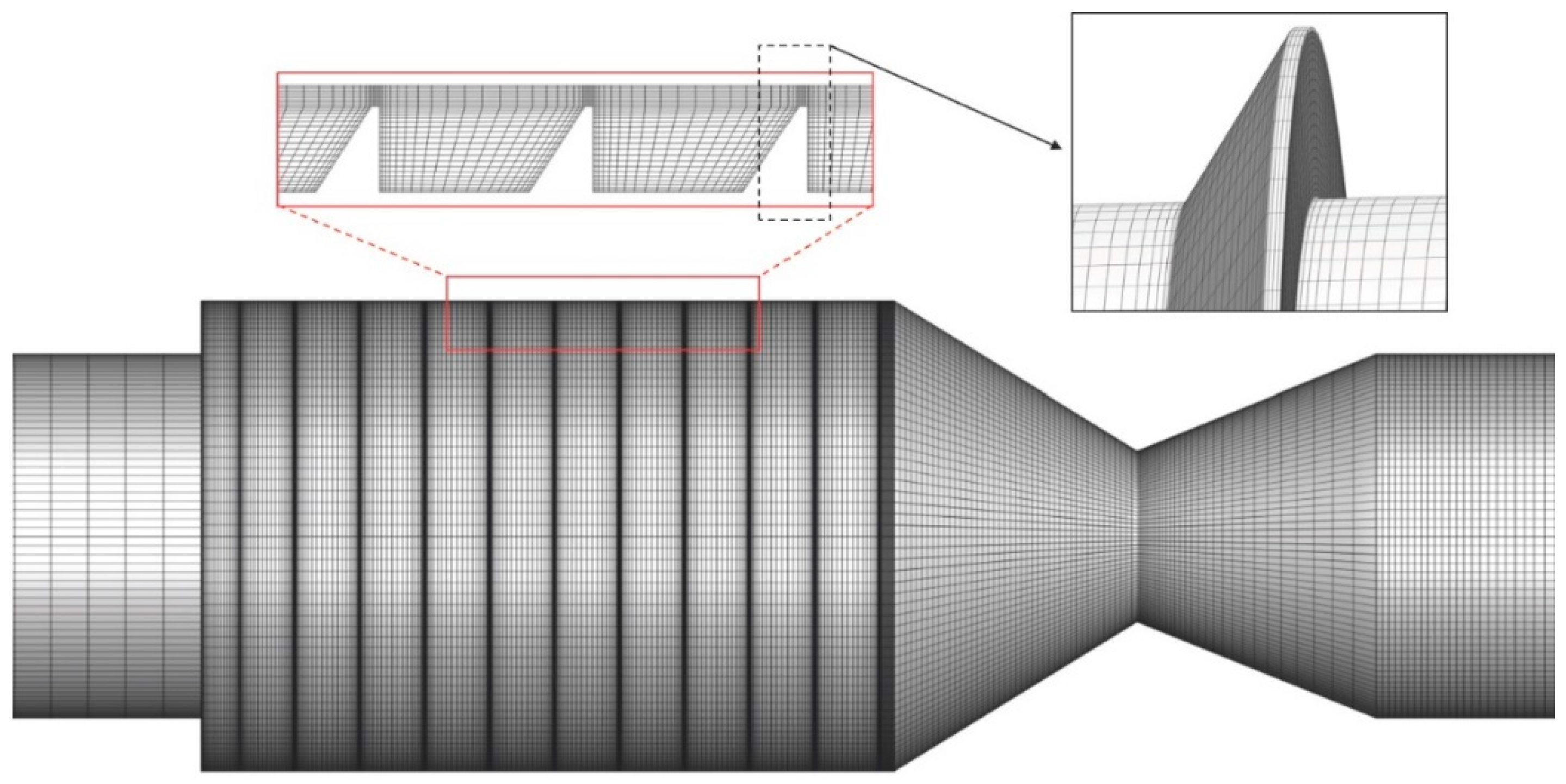
In order to ensure the accuracy of the simulation, it is necessary to verify the grid independence. As shown in Figure 3, structured grids are used in the three models and the grids are refined in areas where the velocity gradient switches rapidly, such as the nozzle structure. Additionally, in order to capture the details of the boundary layer, the grids near the wall are also refined. The height of the first grid layer is 5 × 10⁻³ mm, and subsequently the grid cells extend outward along the wall at a ratio of 1.1. As shown in Table 3, LSS, CSS, and PDS use three sets of grids from coarse to finer. The study of grid independence is to gradually adjust the number of grids until the outlet axial velocity and the leakage rate remains basically unchanged.
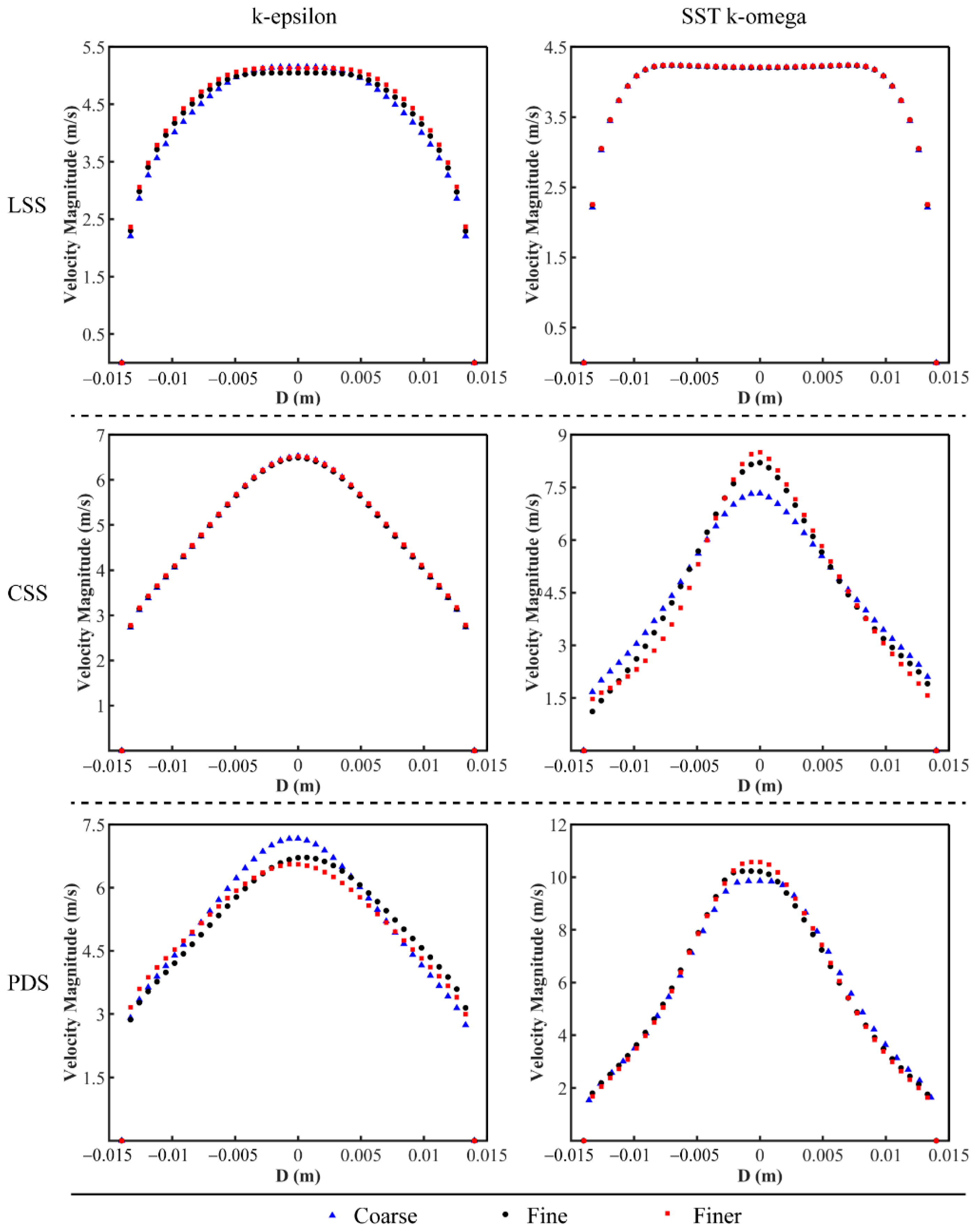
Figure 4 represents the outlet axial velocity distribution of LSS, CSS and PDS under three different precision grids. It can be seen from Figure 4 that the outlet axial velocity distribution of LSS, CSS and PDS, obtained by the simulation in the fine grid, is basically consistent with the consequence under the finer grid, and the maximum relative deviation is less than 10%. Furthermore, the leakage rates under different grid numbers and different turbulence models are compared, as shown in Figure 5. It can be seen from Figure 5 that when the turbulence model is k-ε, the relative differences of the leakage rate between the coarse mesh and the finer mesh of LSS, CSS and PDS are 0.90%, 0.37% and 1.64%, respectively, and the relative differences of the leakage rate between the fine mesh and the finer mesh of LSS, CSS and PDS are 0.03%, 0.42% and 0.27%, respectively. When the turbulence model is SST k-ω, the relative differences of the leakage rate between the coarse mesh and the finer mesh of LSS, CSS and PDS are 0.11%, 3.73% and 1.64%, respectively, and the relative differences of the leakage rate between the fine mesh and the finer mesh of LSS, CSS and PDS are 0.02%, 2.12% and 0.72%, respectively. Taking accuracy and calculation time into account, the final grid numbers of the three models of LSS, CSS and PDS are 2 million, 3.06 million and 3.18 million, respectively.

3. Results

3.1. Verification of Numerical Results

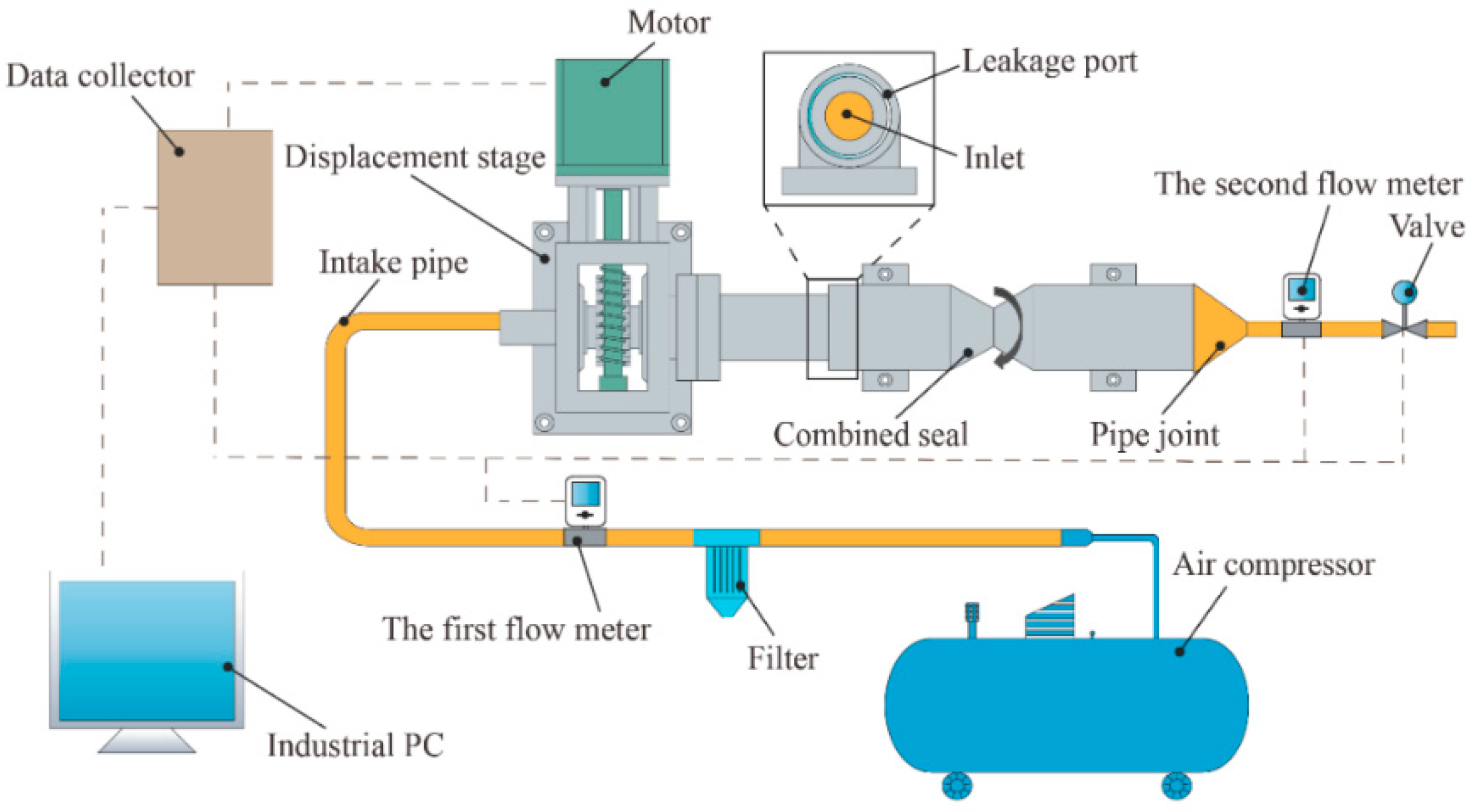
The numerical calculation results of CSS and the test results are compared to verify the accuracy and reliability of the numerical method under rotational conditions. The test results are obtained on the rotational test platform, and the schematic diagram of the rotational test platform is shown in Figure 6. The rotational system consists of a motor, gears and a displacement platform. The motor and gears can drive the model to rotate and control the speed. The displacement platform can accurately ensure the installation position of the model and prevent eccentricity. The compressed air provided by the air compressor passes through the filter device and is dried and subsequently input to the intake pipe. After being measured by the first flow meter, the gas finally enters the intake port of the model. The model outlet is connected to the second flow meter and a pressure control valve that controls the pressure at the outlet.
The shape, size and boundary conditions of the numerical calculation model are consistent with the test seals and test working conditions. In the test, the speed is 400 r/min, the outlet pressure is set to 4000 Pa, the leakage port is connected to the outside atmosphere, and the flow rate varies from 100 L/min to 200 L/min. As shown in Figure 7, the numerical results are in good agreement with the experimental results, and the maximum relative error is less than 8%, which proves that the numerical model in this paper has high reliability. Additionally, compared with the results obtained by the SST k-ω model, the results obtained by the k-ε model are closer to the experimental results, indicating that the k-ε model is more suitable for the simulation of leakage characteristics in this study. Therefore, the turbulence model in subsequent simulations will adopt the k-ε model to ensure high simulation accuracy.

3.2. Leakage Rate at Different Rotational Speeds

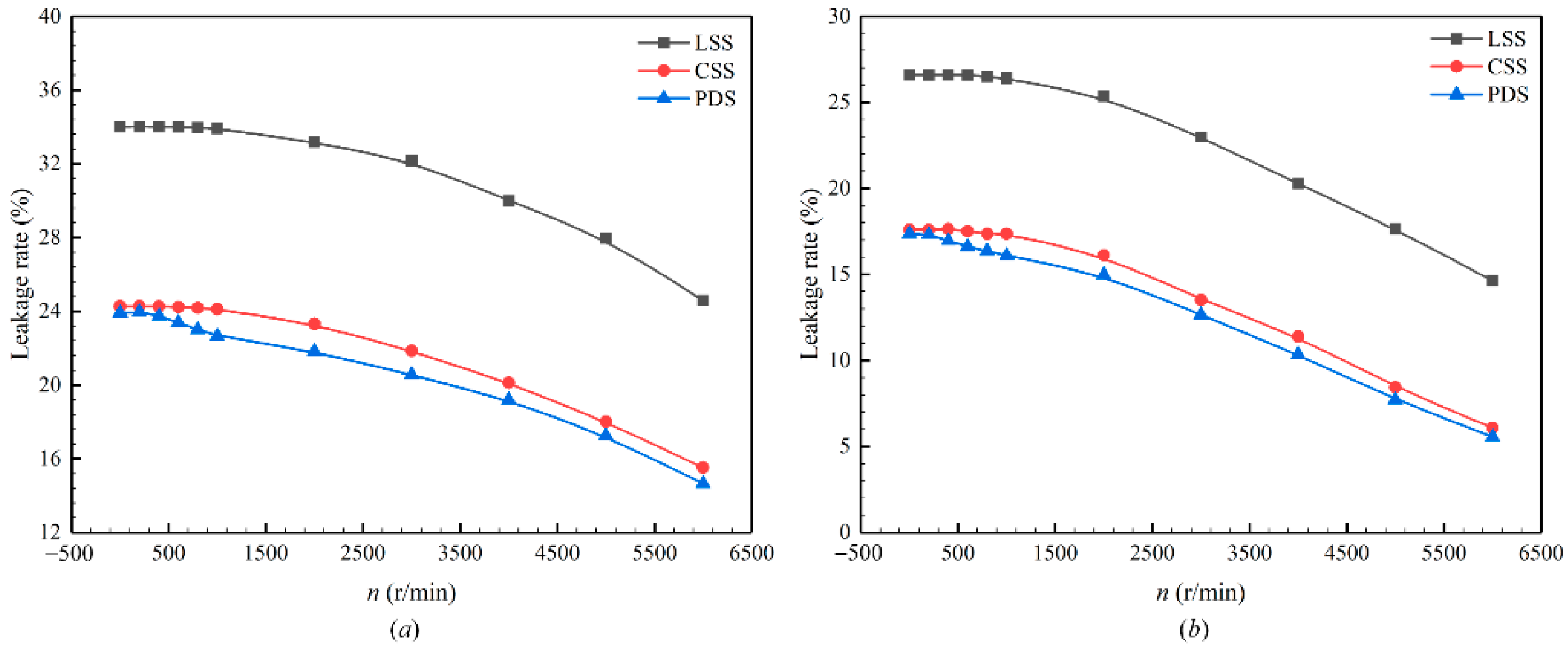
The rotation of the sealing system will affect the internal flow field distribution, which in turn affects the leakage rate. In this section, the preferred numerical calculation model mentioned earlier is used to study the influence of speed on leakage characteristics. Figure 8 represents the relationship between the leakage rate and the rotational speed when the rotational speed changes in the range of 0–6000 r/min under the pressure ratio conditions of 0.25 and 0.50, respectively, for the three sealing structures. It can be seen from the figure that when the pressure ratio is constant, as the speed increases, the leakage rate decreases accordingly. However, the change in the leakage rate is not evident when the rotational speed is small, such as when it is lower than 1000 r/min. When the rotational speed continues to increase, the leakage rate will decrease significantly, which is consistent with the results obtained by Li et al. [29]. When the pressure ratio is 0.25 and the rotation speed is 6000 r/min, the leakage rates of LSS, CSS and PDS are reduced by 9.4%, 8.7%, and 9.3%, respectively, compared with the non-rotating condition. When the pressure ratio is 0.5 and the rotational speed is 6000 r/min, the leakage rates of LSS, CSS and PDS are reduced by 12.0%, 11.5%, and 11.8%, respectively, compared with the non-rotating condition. Therefore, when the rotational speed is high, the sealing performance of the three sealing structures is significantly improved compared with the non-rotating state. When the axial length and pressure ratio of the sealing structure are the same and the rotational speed is 6000 r/min, the leakage rate of CSS is about 8.56–9.06% less than that of LSS, and about 0.51–0.87% more than that of PDS. Additionally, compared with PDS, the leakage rate of CSS is similar, so that the CSS can be used to replace PDS, which can meet the requirements of low leakage rate while reducing the difficulty of manufacturability.
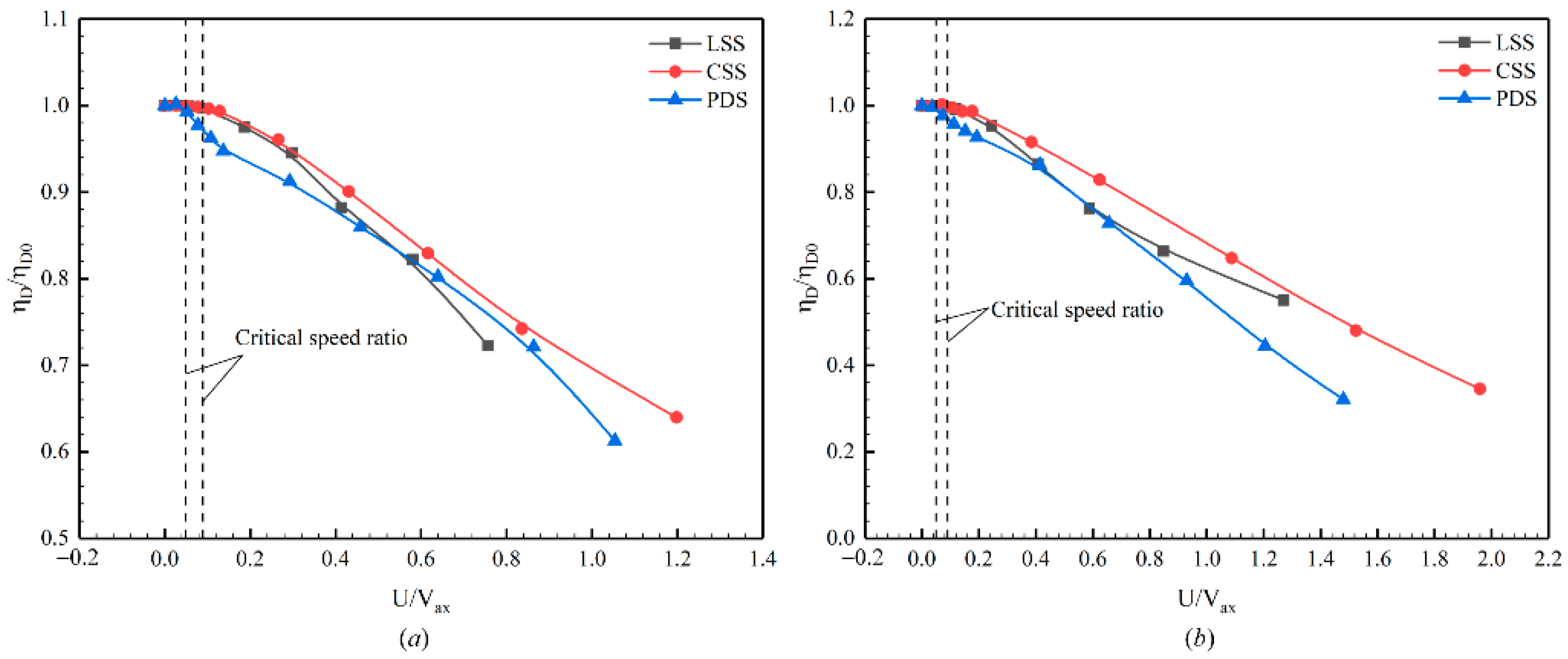
In order to obtain the general law of the change of leakage rate with rotational speed, the influence of the radius of the sealed rotor is taken into consideration, and the relative leakage rate and the speed ratio are introduced. The relative leakage rate is defined as the ratio of the leakage rate η D 0 under rotational condition to the leakage rate η D under non-rotating condition, so that the leakage rate changes with the rotational speed are processed without dimension. The speed ratio U / V a x is the ratio of the circumferential speed U of the rotor surface to the axial speed V a x (the maximum speed in the axial direction at the last sealed tooth tip gap along the fluid direction) of the fluid. As shown in Figure 9, the relationship of η D / η D 0 and U / V a x is obtained for the three sealing structures under the conditions of 0.25 and 0.50 pressure ratio, respectively. It can be seen from the figure that there is a critical value for the speed ratio. When the speed ratio is less than this critical value, its influence on η D / η D 0 is not apparent. When the speed ratio is greater than this critical value, it has a significant influence on η D / η D 0 , and as the speed ratio increases, the influence gradually increases. The critical speed ratio of LSS and CSS is about 0.09, and the speed is about 1000 r/min. The critical speed ratio of PDS is about 0.05, which is smaller than the speed ratio of LSS and CSS, and the speed is about 500 r/min. It demonstrates that the leakage rate of PDS is more obviously affected by the speed. When the pressure ratio is 0.25 and the rotation speed is 6000 r/min, the maximum value of U / V a x for the three sealing structures is 1.25. In comparison with non-rotating conditions, the relative leakage rate is reduced by 28% to 37%. When the pressure ratio is 0.5 and the rotation speed is 6000 r/min, the maximum value of U / V a x for the three sealing structures is 2.20, and the relative leakage rate is reduced by 45% to 68%.
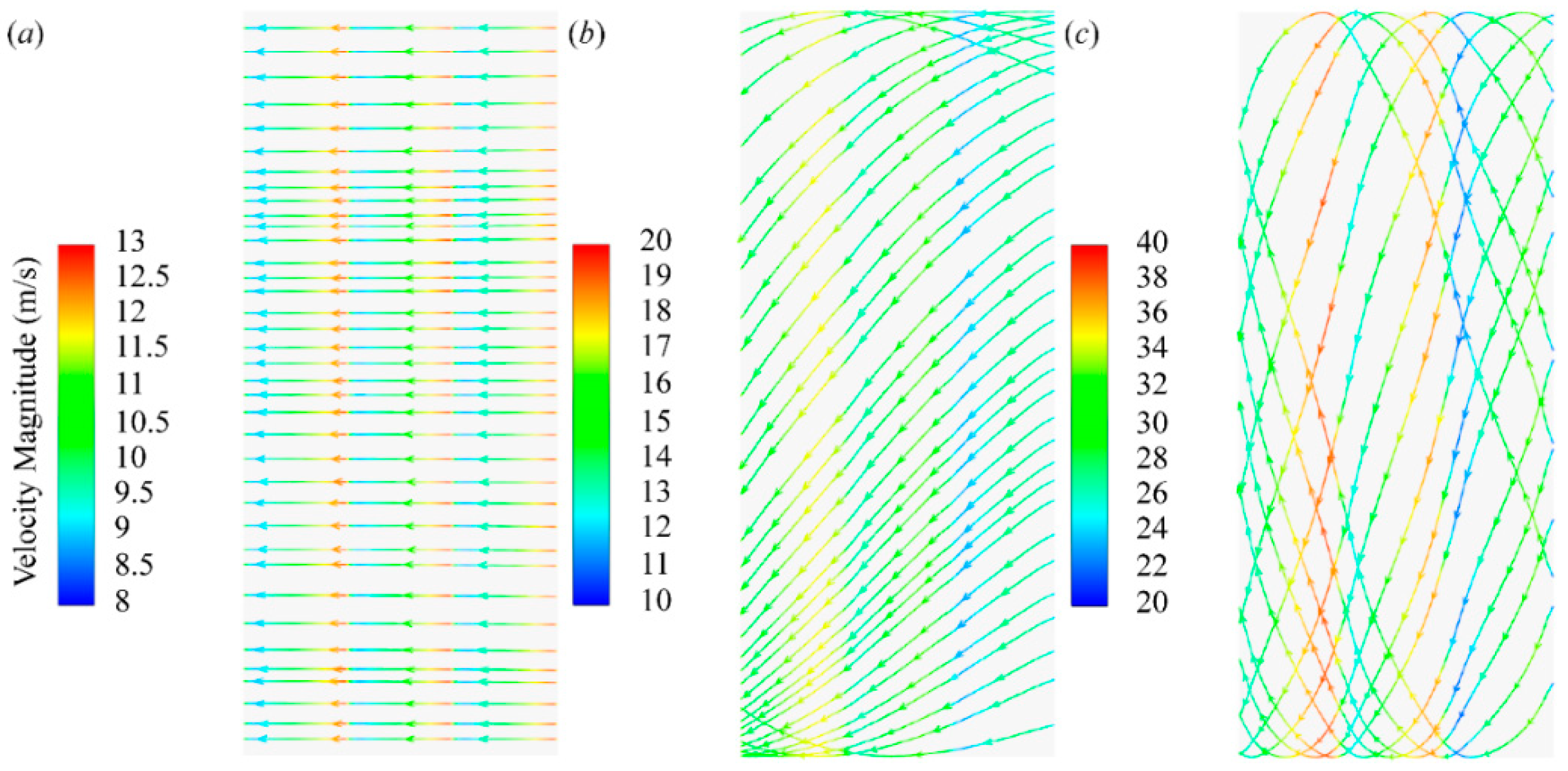
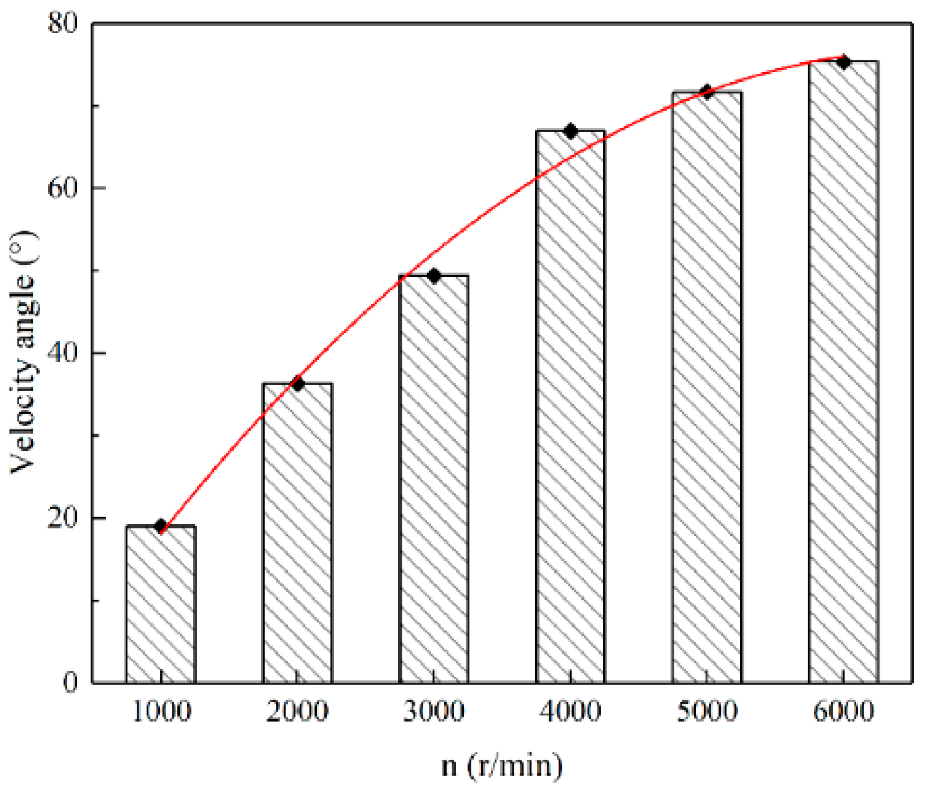
Figure 10 represents the flow lines at the seal gap of CSS at different speeds at a pressure ratio of 0.5. Figure 11 shows the angle between the CSS streamline and the axial direction at different speeds. When the rotational speed is zero, the sealing medium is not affected by centrifugal force and is evenly distributed in the sealed cavity. At this time, the streamline at the sealing gap is along the axial direction. When the rotational speed is 2000 r/min, there is an included angle between the streamline and the axial direction at the sealing gap. As the rotational speed increases, the included angle also increases, resulting in a reduction in the effective flow area in the corresponding sealing gap; that is, the leakage flow through the sealing gap is reduced. Therefore, when the rotor rotates at a low speed, the tangential force provided by the rotation is small, and the leakage of the sealing structure is slightly reduced. When the rotor rotates at high speed, the spiral flow adds a larger tangential force to the sealing medium, which makes the axial velocity of the sealing medium deviate to the circumferential direction under the action of the rotational centrifugal force. The action of rotational centrifugal force increases the flow resistance and dissipation loss, thus reducing the leakage of the sealing gap and improving the performance of the sealing structure.

3.3. Leakage Rate at Different Pressure Ratios

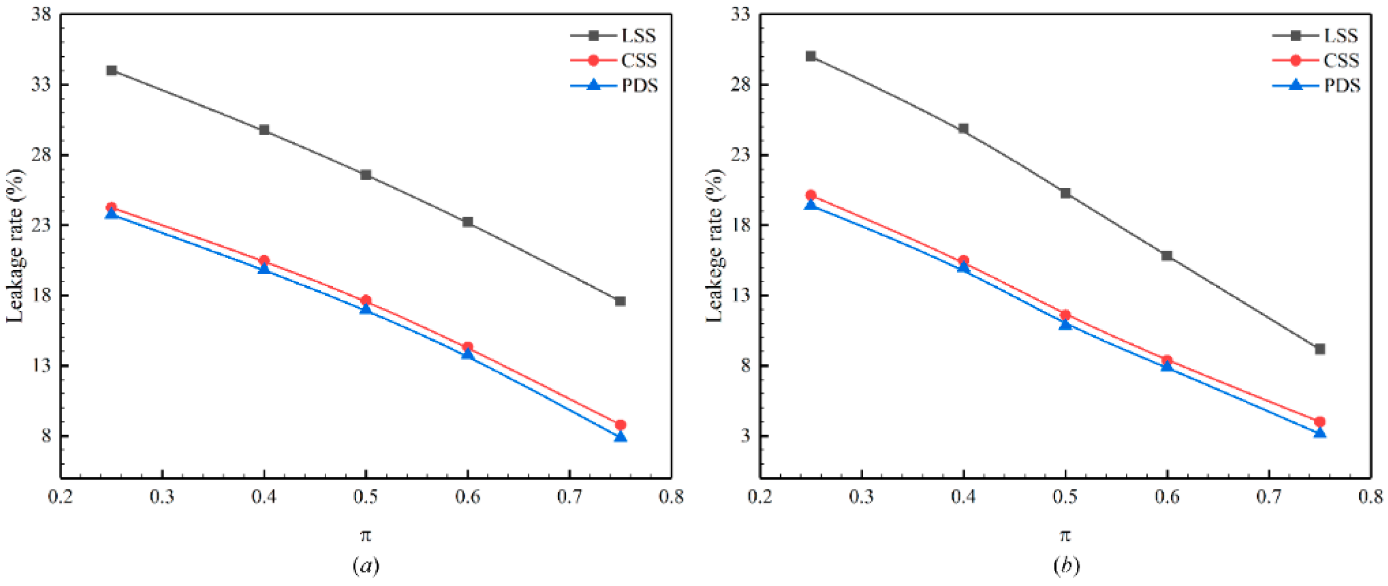
When studying the influence of the pressure ratio on the leakage characteristics of the three types of sealing structures, the calculation model and boundary conditions are the same as in the previous section. The outlet pressure is 4 kPa and the rotational speed is 400 r/min and 4000 r/min, respectively, and the pressure ratio π varies from 0.25 to 0.75.
Figure 12 represents the variation of the leakage rate with the pressure ratio of the three sealing structures of LSS, CSS and PDS at two speeds of 400 r/min and 4000 r/min. It can be seen from the figure that the leakage rates of the three sealing structures decrease with the increase in the pressure ratio, and the change curve is approximately linear. Zhang et al. [9] simulated the sealing performance of Mixed labyrinth seal (MLS) and Staggered labyrinth seal (SLS) and found that the leakage rate followed the same linear trend with the pressure ratio, but increased linearly with the increasing pressure ratio. The reason for the difference with the results in this paper may be due to the difference in structure. Moreover, no matter how large the pressure ratio is, the leakage rate decreases in the order of LSS > CSS > PDS. Additionally, the leakage rates of LSS and PDS are relatively close. To name only a few, when the pressure ratio is 0.5 and the speed is 400 r/min, in comparison with LSS, the leakage rates of CSS and PDS are reduced by about 10% and 11%, respectively, which is the same as when the pressure ratio is 0.5 and the speed is 4000 r/min. It can be concluded that the nozzle structure in CSS and PDS can effectively improve the sealing characteristics of rotational machinery. In comparison with CSS, the leakage rate of PDS is merely reduced by about 1%, indicating that the clapboard structure of PDS in rotational machinery exerts an insignificant influence on the improvement of the sealing effect, which is also illustrated in Sheng’s research [38].

4. Discussion

From the results in Section 3, it can be found that the leakage rate of CSS and PDS with nozzle structure is lower than that of LSS. It is speculated that the existence of the jet structure reduces the pressure difference between the jet structure and the outside, thereby reducing leakage. The jet structure is designed according to Bernoulli principle and adopts reasonable geometric surface parameters. The key parameters are the shape of the jet structure, the extended section, the position of the guide tube and the radius of the jet structure. Therefore, in order to study the sealing mechanism of CSS, it is necessary to discuss the above-mentioned influencing parameters.
For computational simplicity, a 2D model was used in the discussion of the sealing mechanism of the CSS. The mesh was also used as a structured mesh and the mesh independence was verified. The following numerical calculations are based on non-rotational conditions with a velocity inlet with a velocity of 5.41 m/s, a pressure outlet with a standard atmospheric pressure outside, a non-slip wall surface and a porous media boundary (Porous Jump) for the simulation of the internal resistance [39,40]. In addition, air was used as the sealing medium and the standard k-ε model was used for turbulence closure.

4.1. Effect of Jet Structure Shape on Leakage Characteristics

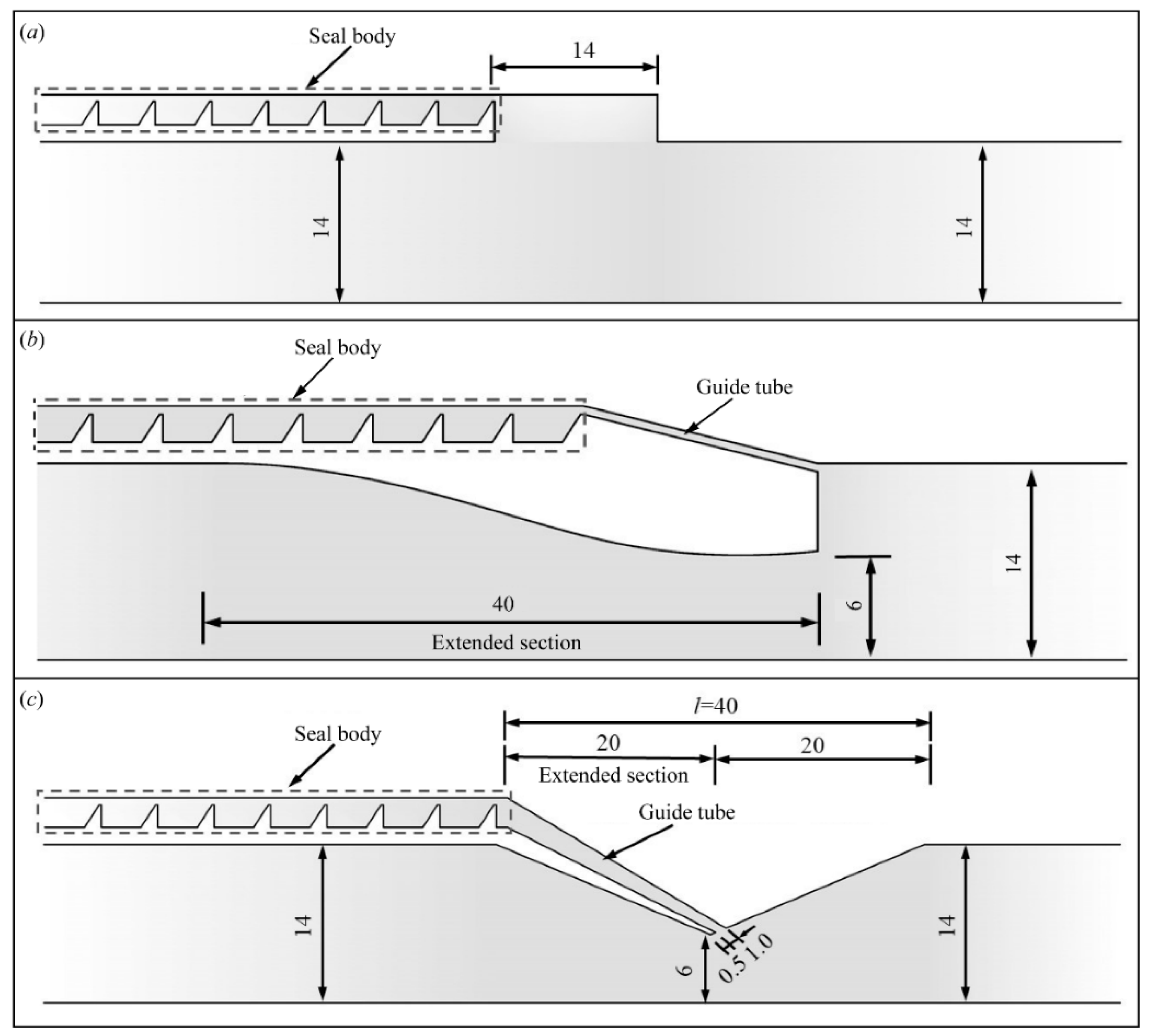
The leakage characteristics of three jet structures, namely the traditional sealing structure, the backward step structure and the nozzle structure, are compared, as shown in Figure 13. The throat radius of the rear step structure is 6 mm, the tilt gap is 1.0 mm, and the length of the extended section is 40 mm. Compared with the backward step structure, the nozzle structure changes the position of the throat, the length of the extended section is reduced to 20 mm, and the minimum tilt gap is 1.0 mm.
Table 4 shows the leakage rate under three jet structures of a traditional labyrinth seal, backward step structure and nozzle structure. It can be seen from Table 4 that when ΔP is 2000 Pa, the leakage rate of the backward step structure is about 14% less than that of the traditional labyrinth seal, and the leakage rate of the nozzle structure is about 30% less than that of the traditional labyrinth seal. When ΔP is 4000 Pa, the leakage rate of the backward step structure is about 13% less than that of the traditional labyrinth seal, and the leakage rate of the nozzle structure is about 35% less than that of the traditional labyrinth seal. Therefore, under the same ΔP, the sealing performance of the nozzle structure is better than that of the backward step structure.

4.2. Effect of Extended Section on Leakage Characteristics

Due to the symmetry of the model, the extended section can be seen as a two-dimensional line rotating around the axis. The main influencing factors of the extended section on the leakage characteristics of CSS are the two-dimensional line style and the length of the extended section. Among them, the styles of the two-dimensional lines are spline curves and straight lines, and the lengths of the extended sections are 20 mm, 25 mm, 30 mm, and 35 mm, respectively.
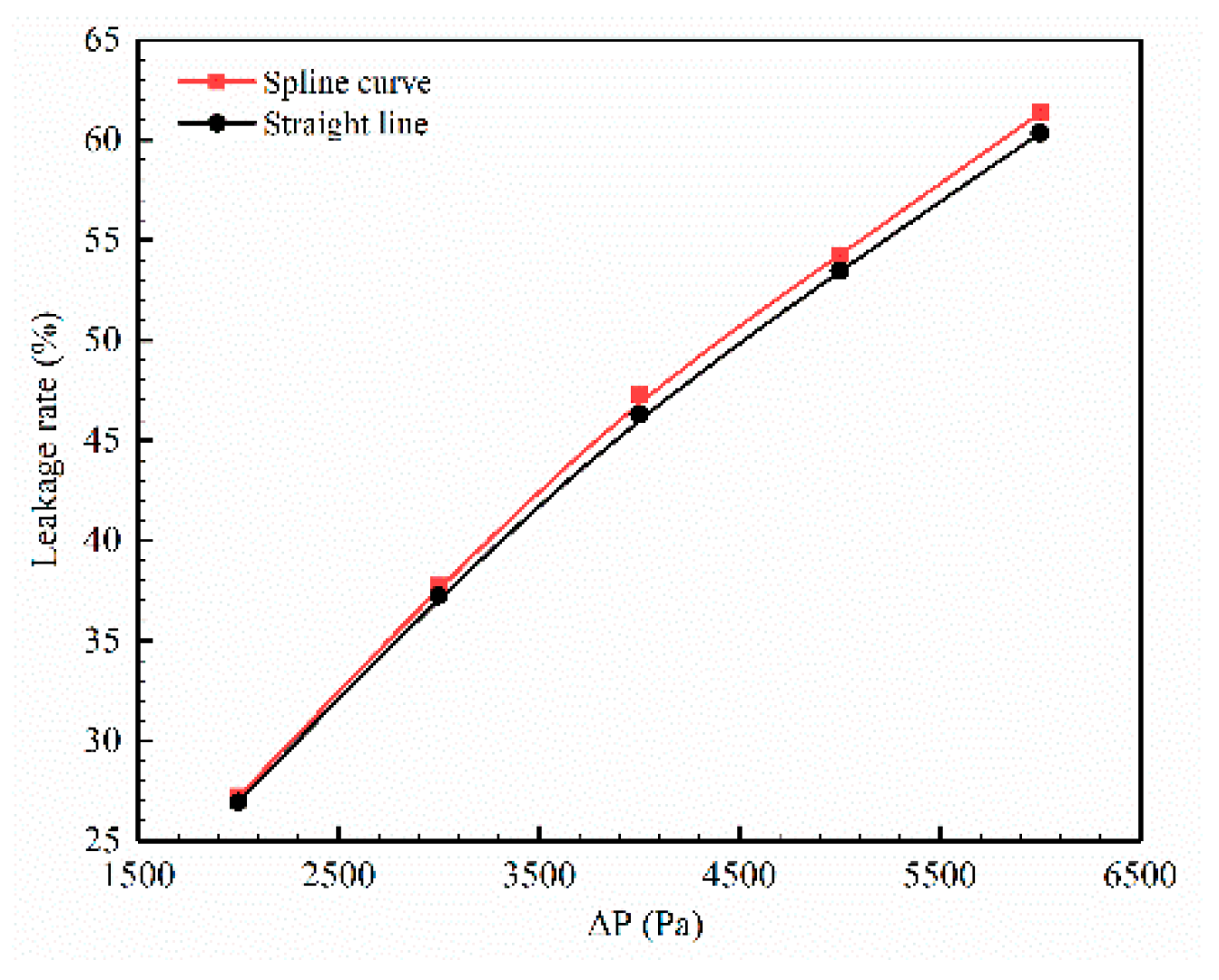
The comparison of the leakage rate of CSS under different two-dimensional line styles is shown in Figure 14. The leakage rates of the two two-dimensional line styles both increase approximately linearly with the increase in ∆P. Under the same ∆P, the leakage rate when the two-dimensional line style is a spline curve is slightly greater than the leakage rate when the two-dimensional line style is a straight line. When ∆P is 2000 Pa, the leakage rate when the two-dimensional line style is a spline curve is increased by about 0.3% compared to the straight line style. When ∆P is 6000 Pa, the leakage rate when the two-dimensional line style is a spline curve is increased by about 1% compared to the straight line style. The two-dimensional line style has a small effect on the leakage characteristics and is almost negligible. Therefore, it is reasonable to use a straight line for the two-dimensional line style, which can also greatly reduce the difficulty of processing and installation.
Table 5 shows the leakage rate of CSS under different lengths of extended section when the two-dimensional line is a straight line. It can be seen from Table 5 that when ΔP is constant, the longer the length of the extended section, the higher the leakage rate. When ΔP is 2000 Pa, the leakage rate of the extended section with a length of 35 mm increases by about 0.7% compared with the leakage rate of extended section with a length of 20 mm. When ΔP is 4000 Pa, the leakage rate of extended section length of 35 mm is about 1% higher than that of the extended section length of 20 mm. Although the longer the length of the extended section, the greater the leakage rate of CSS, the numerical calculation results show that the change of the length of extended section within a certain range has less influence on the flow field characteristics and leakage characteristics of CSS.

4.3. Effect of Position of Guide Tube on Leakage Characteristics

The position of the guide tube before and after the throat will affect the leakage characteristics of CSS. As shown in Figure 15, the position of the guide tube is arranged on the left and right sides of the throat, respectively, and the distance from the throat is 0.5 mm and 1.0 mm, respectively. Table 6 shows the leakage rate of CSS under different positions of the guide tube and ΔP. It can be seen from Table 6 that when the distance between the guide tube and the throat is constant, the leakage rate when the guide tube is on the left side of the throat is much smaller than the leakage rate when the lead pipe is on the right side of the throat. It can be seen from Figure 16 that when the fluid flows through the throat position, a backflow will be formed. When the guide tube is located on the right side of the throat, the backflow is large, thus causing a large leak. When the guide tube is located on the left side of the throat, because the inclined gap is placed in the direction of the fluid flow, the backflow is small, so the leakage is also small. However, in industrial manufacture, when the guide tube is located on the left side of the throat, the processing difficulty and installation degree will increase sharply due to the thin wall surface. Therefore, the selection of the guide tube position should consider various factors such as manufacturing accuracy and sealing performance.

4.4. Effect of Nozzle Radius on Leakage Characteristics

In the previous work, the influence of the nozzle radius on the leakage characteristics was discussed, and it was found that as the nozzle radius increases, the pressure difference before and after the throat gradually becomes smaller. This is because when the fluid passes through the nozzle structure, due to the small diameter of the throat, the flow rate increases and the pressure decreases; and after the fluid passes through the throat, the pipe diameter increases and the flow rate decreases, resulting in an increase in pressure. The smaller the nozzle radius, the more significant the change in flow rate and pressure. Therefore, the size of the nozzle radius has a significant impact on the jet effect of the nozzle structure. The smaller the nozzle radius, the stronger the jet effect, the lower the pressure near the throat, and the greater the pressure difference from the outside, which prevents the leaking of gas to the outside.

5. Conclusions

Based on numerical simulation, this study investigated the leakage characteristics of the CSS under rotational conditions using a 3D model, compared it with LSS and PDS and analyzed the influence of different parameters (pressure ratio and rotational speed) on the leakage rates of the seal structure. In addition, the sealing mechanism of CSS was discussed. For computational simplicity, a 2D model was used in the discussion of the sealing mechanism of the CSS. The main conclusions are as follows:
(1) The experimental results reveal that the k-ε model is more suitable for the simulation of the sealing structure in this study compared with the SST k-ω model. At different inlet flow rates, the difference between the numerical results and the experimental results is slightly different, but the maximum relative error is less than 8%, which proves that the numerical method used in this study has a high reliability.
(2) Under the same pressure ratio, the leakage rates of the three sealing structures all decrease with the increase in speed. At a pressure ratio of 0.25 and a speed of 6000 r/min, the leakage rates are reduced by 9.4%, 8.7% and 9.3% for LSS, CSS and PDS, respectively, compared to the non-rotating condition. At a pressure ratio of 0.5 and a speed of 6000 r/min, the leakage rates for LSS, CSS and PDS are reduced by 12.0%, 11.5% and 11.8%, respectively, compared to the non-rotating condition. The CSS has a similar leakage rate compared to the PDS and can therefore be used as a replacement for the PDS to meet the low leakage rate requirement while reducing manufacturing difficulties. The relative speed ratio has a critical value. When the relative speed ratio is lower than this value, the leakage of the sealing structure changes less. When the relative speed ratio exceeds this value, the leakage of the sealing structure decreases significantly as the speed increases. The critical value of the speed ratio of CSS is similar to that of LSS, which is about 1000 r/min, while the critical value of the speed ratio of PDS is minor, and the critical speed is about 500 r/min at this time.
(3) The leakage rates of the three sealing structures all decrease with the increase in the pressure ratio. Regardless of the pressure ratio, the leakage rate decreases in the order LSS > CSS > PDS. At a pressure ratio of 0.5 and a speed of 400 r/min, the leakage rates of CSS and PDS are reduced by approximately 10% and 11%, respectively, compared to LSS. This indicates that the nozzle structure in the CSS and PDS can effectively improve the sealing characteristics of rotating machinery. Compared to CSS, the leakage rate of PDS is only reduced by about 1%, indicating that the spacer structure in PDS in rotating machinery has little effect on the improvement of the sealing effect.
(4) The jet structure in CSS is a key factor affecting the sealing characteristics. Compared with the backward step structure, the nozzle structure has a better sealing effect. The two-dimensional line style and the length of the extended section in the geometric surface form of the jet structure have little effect on the leakage characteristics of the combined seal. The leakage rate when the guide tube is on the left side of the throat is less than the leakage rate when the guide tube is on the right side of the throat. The nozzle radius has a significant influence on the sealing characteristics of the sealing structure. The larger the nozzle radius, the greater the leakage rate of CSS.

Author Contributions

Conceptualization, B.Z. and J.L.; methodology, B.Z.; software, B.Z. and J.L.; validation, B.Z., X.F. and S.Y.; formal analysis, B.Z. and S.Y.; investigation, B.Z. and J.L.; resources, X.F. and S.Y.; data curation, J.L.; writing—original draft preparation, B.Z. and J.L.; writing—review and editing, B.Z.; visualization, B.Z. and S.Y.; supervision, X.F. and S.Y.; project administration, X.F. and S.Y.; funding acquisition, X.F. All authors have read and agreed to the published version of the manuscript.

Funding

This research was funded by the National Natural Science Foundation of China, grant number 51879191.

Institutional Review Board Statement

Not applicable.

Informed Consent Statement

Not applicable.

Data Availability Statement

The datasets used and analyzed during the current study are available from the corresponding author on reasonable request.

Acknowledgments

Not applicable.

Conflicts of Interest

The authors declare no conflict of interest.

Nomenclature and Abbreviations

cseal clearance, mmnrotational speed, r/min
htooth height, mmηleakage rate, %
stooth pitch, mmπpressure ratio
rnozzle radius, mmΔPinternal resistance of the device, Pa
lnozzle length, mmLSSlabyrinth seal structure
ttooth thickness, mmCSScombined seal structure
Rinintake pipe radius, mmPDSpocket damping seal structure

References

  1. Chupp, R.E.; Hendricks, R.C.; Lattime, S.B.; Steinetz, B.M. Sealing in turbomachinery. J. Propul. Power 2006, 22, 313–349. [Google Scholar] [CrossRef]
  2. Zhou, D.; Izumi, M.; Miki, M.; Felder, B.; Ida, T.; Kitano, M. An overview of rotating machine systems with high-temperature bulk superconductors. Supercond. Sci. Technol. 2012, 25, 103001. [Google Scholar] [CrossRef]
  3. Kalsi, S.; Badcock, R.A.; Hamilton, K. Coolant transfer coupling with integrated dynamo for rotor with HTS windings. IOP Conf. Series Mater. Sci. Eng. 2020, 756, 012029. [Google Scholar] [CrossRef]
  4. Zhao, X.X.; Zhang, S.S.; Zhou, C.L.; Hu, Z.M.; Li, R.; Jiang, J.H. Experimental study of hydraulic cylinder leakage and fault feature extraction based on wavelet packet analysis. Comput. Fluids. 2015, 106, 33–40. [Google Scholar] [CrossRef]
  5. Schaller, A.; Darvishsefat, N.; Schlucker, E. Simulation and experimental investigation of labyrinth seals for reciprocating piston compressors. Chem. Eng. Technol. 2018, 41, 1043–1050. [Google Scholar] [CrossRef]
  6. Wang, G.Q.; Guo, C.F.; Xu, Z.C.; Yu, Y.L.; Ji, J.B. A new crossflow rotating bed, Part 2: Structure optimization. Ind. Eng. Chem. Res. 2014, 53, 4038–4045. [Google Scholar] [CrossRef]
  7. Neumann, K.; Hunold, S.; Skiborowski, M.; Gorak, A. Dry pressure drop in rotating packed beds-systematic experimental studies. Ind. Eng. Chem. Res. 2017, 56, 12395–12405. [Google Scholar] [CrossRef]
  8. Asok, S.P.; Sankaranarayanasamy, K.; Sundararajan, T.; Vaidyanathan, G.; Kumar, K.U. Pressure drop and cavitation investigations on static helical-grooved square, triangular and curved cavity liquid labyrinth seals. Nucl. Eng. Des. 2011, 241, 843–853. [Google Scholar] [CrossRef]
  9. Zhang, M.J.; Yang, J.G.; Xu, W.J.; Xia, Y.L. Leakage and rotordynamic performance of a mixed labyrinth seal compared with that of a staggered labyrinth seal. J. Mech. Sci. Technol. 2017, 31, 2261–2277. [Google Scholar] [CrossRef]
  10. Cangioli, F.; Vannini, G.; Chirathadam, T. A novel bulk-flow model for pocket damper seals. J. Eng. Gas Turbines Power 2020, 142, 011012. [Google Scholar] [CrossRef]
  11. Griebel, C. Impact analysis of pocket damper seal geometry variations on leakage performance and rotordynamic force coefficients using computational fluid dynamics. J. Eng. Gas Turbines Power 2019, 141, 041024. [Google Scholar] [CrossRef]
  12. Jia, X.Y.; Zheng, Q.; Jiang, Y.T.; Zhang, H. Leakage and rotordynamic performance of T type labyrinth seal. Aerosp. Sci. Technol. 2019, 88, 22–31. [Google Scholar] [CrossRef]
  13. Cangioli, F.; Vannini, G.; Pennacchi, P.; Ciuchicchi, L.; Nettis, L.; Chatterton, S. Rotordynamic characterization of a staggered labyrinth seal: Experimental test data and comparison with predictions. J. Eng. Gas Turbines Power 2018, 141, 011009. [Google Scholar] [CrossRef]
  14. Li, Z.G.; Li, J.; Yan, X.; Feng, Z.P. Effects of pressure ratio and rotational speed on leakage flow and cavity pressure in the staggered labyrinth seal. J. Eng. Gas Turbines Power 2011, 133, 114503. [Google Scholar] [CrossRef]
  15. He, K.; Li, J.; Yan, X.; Feng, Z.P. Investigations of the conjugate heat transfer and windage effect in stepped labyrinth seals. Int. J. Heat Mass Tran. 2012, 55, 4536–4547. [Google Scholar] [CrossRef]
  16. Lin, Z.R.; Wang, X.D.; Yuan, X.; Shibukawa, N.; Noguchi, T. Investigation and improvement of the staggered labyrinth seal. Chin. J. Mech. Eng.-En. 2015, 28, 402–408. [Google Scholar] [CrossRef]
  17. Szymański, A.; Wróblewski, W.; Bochon, K.; Majkut, M.; Strozik, M.; Marugi, K. Experimental validation of optimised straight-through labyrinth seals with various land structures. Int. J. Heat Mass Transf. 2020, 158, 119930. [Google Scholar] [CrossRef]
  18. Asok, S.P.; Sankaranarayanasamy, K.; Sundararajan, T.; Rajesh, K.; Ganeshan, G.S. Neural network and CFD-based optimisation of square cavity and curved cavity static labyrinth seals. Tribol. Int. 2007, 40, 1204–1216. [Google Scholar] [CrossRef]
  19. Li, Z.G.; Li, J.; Feng, Z.P. Labyrinth seal rotordynamic characteristics Part II: Geometrical parameter effects. J. Propul. Power 2016, 32, 1281–1291. [Google Scholar] [CrossRef]
  20. Li, Z.G.; Li, J.; Feng, Z.P. Labyrinth seal rotordynamic characteristics Part I: Operational conditions effects. J. Propul. Power 2016, 32, 1199–1211. [Google Scholar] [CrossRef]
  21. Kim, T.S.; Cha, K.S. Comparative analysis of the influence of labyrinth seal configuration on leakage behavior. J. Mech. Sci. Technol. 2009, 23, 2830–2838. [Google Scholar] [CrossRef]
  22. Vance, J.M.; Schultz, R.R. A new damper seal for turbomachinery. In Proceedings of the 14th Biennial ASME Conference on Vibration and Noise, Albuquerque, NM, USA, 19–22 September 1993; pp. 139–148. [Google Scholar]
  23. Vance, J.M.; Li, J. Test results of a new damper seal for vibration reduction in turbomachinery. J. Eng. Gas Turbines Power 1996, 118, 843–846. [Google Scholar] [CrossRef] [Green Version]
  24. Li, Z.G.; Li, J.; Feng, Z.P. Numerical investigation on the leakage and static stability characteristics of pocket damper seals at high eccentricity ratios. J. Eng. Gas Turbines Power 2017, 140, 042503. [Google Scholar] [CrossRef]
  25. Waschka, W.; Wittig, S.; Kim, S. Influence of high rotational speeds on the heat-transfer and discharge coefficients in labyrinth seals. J. Turbomach. 1992, 114, 462–468. [Google Scholar] [CrossRef]
  26. Nayak, K.C. Effect of rotation on leakage and windage heating in labyrinth seals with honeycomb lands. J. Eng. Gas Turbines Power 2020, 142, 081001. [Google Scholar] [CrossRef]
  27. Dogu, Y.; Sertçakan, M.C.; Bahar, A.S.; Pişkin, A.; Arıcan, E.; Kocagül, M. Computational fluid dynamics investigation of labyrinth seal leakage performance depending on mushroom-shaped tooth wear. J. Eng. Gas Turbines Power 2015, 138, 032503. [Google Scholar] [CrossRef]
  28. Li, G.Q.; Zhang, Q.; Lei, Z.J.; Huang, E.L.; Wu, H.W.; Xu, G. Leakage performance of labyrinth seal for oil sealing of aero-engine. Propuls. Power Res. 2019, 8, 13–22. [Google Scholar] [CrossRef]
  29. Li, Z.G.; Li, J.; Feng, Z.P. Numerical investigations on the leakage and rotordynamic characteristics of pocket damper seals-Part I: Effects of pressure ratio, rotational speed, and inlet preswirl. J. Eng. Gas Turb. Power 2015, 137, 032503. [Google Scholar] [CrossRef]
  30. Bondarenko, G.A.; Baga, V.N.; Bashlak, I.A. Flow simulation in a labyrinth seal. Appl. Mech. Mater. 2014, 630, 234–239. [Google Scholar] [CrossRef]
  31. Kong, X.Z.; Liu, G.W.; Liu, Y.X.; Zheng, L.X. Experimental testing for the influences of rotation and tip clearance on the labyrinth seal in a compressor stator well. Aerosp. Sci. Technol. 2017, 71, 556–567. [Google Scholar] [CrossRef]
  32. Li, J.; Fu, X.L.; Yan, S.L. Simulation and experimental investigation of a new type of combined seal structure. J. Fluids Eng. 2021, 143, 051503. [Google Scholar] [CrossRef]
  33. Wróblewski, W.; Frączek, D.; Marugi, K. Leakage reduction by optimisation of the straight–through labyrinth seal with a honeycomb and alternative land configurations. Int. J. Heat Mass Transf. 2018, 126, 725–739. [Google Scholar] [CrossRef]
  34. Qin, H.Q.; Lu, D.G.; Zhong, D.W.; Wang, Y.; Song, Y. Experimental and numerical investigation for the geometrical parameters effect on the labyrinth-seal flow characteristics of fast reactor fuel assembly. Ann. Nucl. Energy 2019, 135, 106964. [Google Scholar] [CrossRef]
  35. Wang, N.M.; Wang, Y.R.; Tian, A.M. Influence of structure parameters on aeroelastic stability for labyrinth seal based on energy method. Propuls. Power Res. 2018, 7, 288–295. [Google Scholar] [CrossRef]
  36. ANSYS. ANSYS Fluent theory guide, Release 18.1.; ANSYS: Canonsburg, PA, USA, 2018. [Google Scholar]
  37. Zhang, W.F.; Yang, J.G.; Li, C.; Tian, Y.W. Comparison of leakage performance and fluid-induced force of turbine tip labyrinth seal and a new kind of radial annular seal. Comput. Fluids 2014, 105, 125–137. [Google Scholar] [CrossRef]
  38. Sheng, N.; Ruggiero, E.J.; Devi, R.; Guo, J.P.; Cirri, M. Experimental and analytical leakage characterization of annular gas seals: Honeycomb, labyrinth and pocket damper seals. In Proceedings of the ASME 2011 Turbo Expo: Turbine Technical Conference and Exposition, Vancouver, BC, Canada, 6–10 June 2011; Volume 5, pp. 723–729. [Google Scholar]
  39. Kundu, P.; Kumar, V.; Mishra, I.M. Experimental and numerical investigation of fluid flow hydrodynamics in porous media: Characterization of pre-Darcy, Darcy and non-Darcy flow regimes. Powder Technol. 2016, 303, 278–291. [Google Scholar] [CrossRef]
  40. Dukhan, N.; Bagci, O.; Ozdemir, M. Experimental flow in various porous media and reconciliation of Forchheimer and Ergun relations. Exp. Therm. Fluid Sci. 2014, 57, 425–433. [Google Scholar] [CrossRef]
Figure 1. Schematic and critical dimensions (mm) of (a) LSS, (b) CSS and (c) PDS.
Sustainability 14 03648 g001
Figure 2. Boundary conditions of numerical model.
Sustainability 14 03648 g002
Figure 3. Computational grid of CSS.
Sustainability 14 03648 g003
Figure 4. Axial velocity distribution at the outlet of LSS, CSS and PDS of different grids.
Sustainability 14 03648 g004
Figure 5. The leakage rates of LSS, CSS and PDS under different grid numbers and different turbulence models.
Sustainability 14 03648 g005
Figure 6. Test rig of rotational seal.
Sustainability 14 03648 g006
Figure 7. (a) Simulated and experimental data of leakage rate and (b) relative error at different flows, respectively.
Sustainability 14 03648 g007
Figure 8. The relationship between the leakage rate and the rotational speed when the rotational speed changes in the range of 0–6000 r/min under the pressure ratio conditions of (a) 0.25 and (b) 0.50 for LSS, CSS and PDS.
Sustainability 14 03648 g008
Figure 9. The relationship between η D / η D 0 and U / V a x of the three sealing structures (LSS, CSS and PDS) under the pressure ratio of (a) 0.25 and (b) 0.50, respectively.
Sustainability 14 03648 g009
Figure 10. The streamline of CSS at the tooth tip clearance at (a) 0 r/min, (b) 2000 r/min and (c) 4000 r/min when the pressure ratio is 0.5 at different rotational speeds.
Sustainability 14 03648 g010
Figure 11. The included angle between streamline and axial direction in CSS at different rotational speeds.
Sustainability 14 03648 g011
Figure 12. The relationship between the leakage rate and the pressure ratio when the pressure ratio changes in the range of 0.25–0.75 under the rotational speed conditions of (a) 400 r/min and (b) 4000 r/min for LSS, CSS and PDS.
Sustainability 14 03648 g012
Figure 13. Calculation domain and geometric structure parameters of (a) traditional labyrinth seal structure; (b) backward step structure; and (c) nozzle structure.
Sustainability 14 03648 g013
Figure 14. Leakage rate under different line styles.
Sustainability 14 03648 g014
Figure 15. The structure of the guide tube on the (a) right and (b) left of the throat.
Sustainability 14 03648 g015
Figure 16. The velocity vector when the guide tube is 1.0 mm on the (a) right and (b) left of the throat.
Sustainability 14 03648 g016
Table 1. Parameters of annual seals.
NameDimensionUnit
Seal clearance (c)0.5mm
Tooth height (h)2.0mm
Tooth pitch (s)5.0mm
Nozzle radius (r)6.0mm
Nozzle length (l)40.0mm
Tooth thickness (t)1.0mm
Intake pipe radius (Rin)14.0mm
Table 2. Boundary conditions.
NameMethodsValue
InletVelocity inlet2.71–5.41 m/s
OutletPressure outlet4000 Pa
Leakage portPressure outlet1000–3000 Pa
Moving wallNo slip0–6000 r/min
Stationary wallNo slip-
Table 3. Three sets of grids from coarse to finer corresponding to LSS, CSS and PDS.
ModelsCoarseFineFiner
LSS100 W200 W300 W
CSS120 W238 W306 W
PDS231 W318 W440 W
Table 4. Leakage rate (%) under different jet structure shapes.
ΔP (Pa)Traditional Labyrinth Seal StructureBackward Step StructureNozzle Structure
200056.5642.1726.93
300068.7357.2437.23
400081.6367.1146.29
Table 5. Leakage rate of CSS under different extension section length.
ΔP (Pa)20 mm25 mm30 mm35 mm
200026.9327.4927.5327.65
300037.2337.9538.0338.24
400046.2947.0147.1547.23
Table 6. Leakage rate under different guide tube position and ΔP.
ΔP (Pa)0.5 mm to the Left of the Throat1.0 mm to the Left of the Throat0.5 mm to the Right of the Throat1.0 mm to the Right of the Throat
200011.4912.2926.9828.93
300015.6417.3737.2328.26
400019.4321.3746.2949.21
Publisher’s Note: MDPI stays neutral with regard to jurisdictional claims in published maps and institutional affiliations.