Article

Energy-Saving for Industrial Pneumatic Actuation Systems by Exhausted Air Reuse Based on a Constant Pressure Elastic Accumulator

Ship Electromechanical Equipment Institute, Dalian Maritime University, Dalian 116026, China
*
Author to whom correspondence should be addressed.
Sustainability 2022, 14(6), 3535; https://doi.org/10.3390/su14063535
Submission received: 12 February 2022 / Revised: 12 March 2022 / Accepted: 16 March 2022 / Published: 17 March 2022
(This article belongs to the Topic Industrial Engineering and Management)

Abstract

:
Exhausted air reuse is one of the most important energy-saving methods for pneumatic actuation systems. However, traditional exhausted air storage tanks have the disadvantages of unstable pressure and low energy density. To solve these problems, this paper presents an energy-saving method by exhausted air reuse for industrial pneumatic actuation systems based on a constant pressure elastic accumulator. Employing the hyperelastic mechanical properties of rubber, a constant pressure energy storage accumulator is designed and applied to a pneumatic circuit for exhausted air recovery and energy saving. In the circuit, the accumulator recovers exhausted air from a primary cylinder and supplies it to another secondary cylinder. Then the secondary cylinder no longer needs air supply from the air compressor to achieve the purpose of energy saving. The energy-saving mathematical model of the circuit is established using air consumption, and the system operation test bed is built to verify the energy-saving efficiency. Results show that the maximum energy-saving efficiency of the system is 54.1% under given working conditions, and the stability of the cylinder can be improved.

1. Introduction

As one of the widely used energy sources in industrial fields, compressed air is widely used in all walks of life because of its high speed, cleanliness, safety, low cost, and easy maintenance. However, due to the shortcomings of leakage and compressibility of air, the compressed air utilization rate is quite inefficient. Many scholars have studied compressed air energy saving.
Exhausted air reuse is one of the most effective ways to save energy in pneumatic systems, which can save about 50% of compressed air consumption at most, and it is easy to operate [1]. Yang et al. used a bypass valve to connect the cylinder inlet and exhaust chamber and delivered part of the compressed air in the cylinder exhaust chamber to the inlet chamber for reuse. This method saved about 12–28% energy. Due to the presence of the bypass valve, cylinder drive performance was also improved [2]. Seslija et al. put forward a new type of control mode using a bypass valve together with a PWM control, showing that 30% of energy was saved under the same working conditions in comparison to the traditional PWM control system. However, the tracking performance of the PWM bypass control system was slightly worse because it took more time to reach the required position influenced by gravity and load [3]. Du et al. connected the cylinder inlet and exhaust chamber using an air compressor [4]. By directly controlling the piston rod speed with a motor, 74% compressed air was saved on the premise of ensuring the smooth operation of the piston. However, the applicability and robustness of this method needed to be further verified [5]. Li et al. collected the compressed air from the exhaust chamber through an air tank and then reused it after pressurization; the advantage was that the energy-saving efficiency was high, reaching more than 40%, but the disadvantage was that the back pressure was generated due to the air tank which reduced the piston speed by about 17% [6]. Leszczynski et al. proposed an exhaust recovery energy storage and conversion system, which used an air tank to recover the exhausted air. When the air tank reached a certain pressure, it drove an indirect energy conversion device to generate power and store energy, which saved energy by 31% [7]. Elija et al. put forward a control framework for exhausted air reuse, which saved energy up to 38% under different working conditions [8].
In summary, to avoid complex control algorithms, exhaust energy saving often needs an effective energy storage element. However, as the core energy storage component of exhaust recovery, most of the existing air tanks are of rigid structure. Although they can realize high-pressure storage and long-term air storage, the tanks have heavy volume, poor portability, and they cannot store and discharge energy at a constant pressure, an inability that will increase the system instability during operation [9]. In order to solve this problem, many scholars have studied the constant pressure energy storage device. James et al. proposed a new type of constant pressure hydraulic accumulator based on variable cross-sectional area pistons. The device solved the problem of system pressure change caused by the change of energy stored in the accumulator and reduced the design size of the accumulator. However, the problem with this device was that it was difficult to ensure that the design of the rolling diaphragm seal could meet the life requirements of cyclic use [10]. Wang et al. designed an isobaric compressed air storage tank based on a special shaped cam conversion unit. The pressure fluctuation rate of the air storage device was about 2%, which reduced the energy consumption by about 18.7% compared with the traditional constant volume air storage device. However, the volume of the device was too large to be suitable for the exhaust recovery circuit [
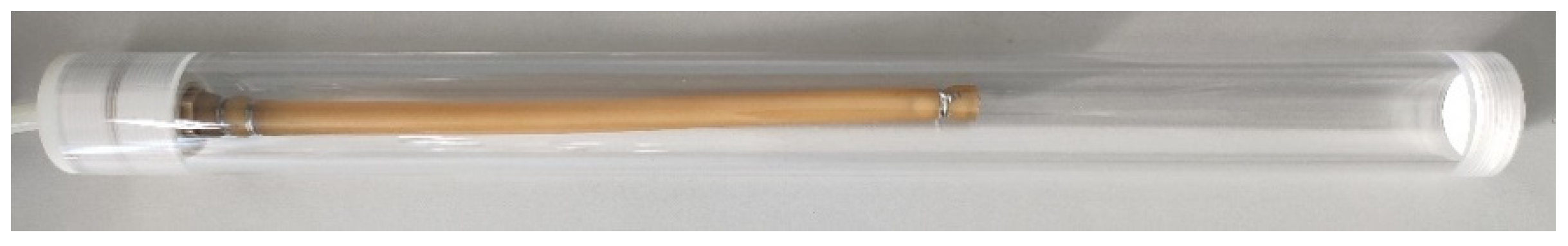
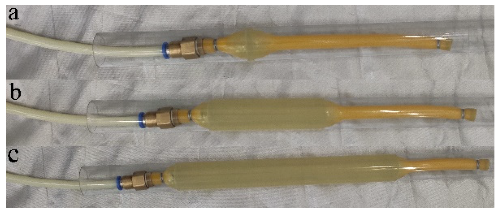
11]. Cummins et al. presented a pneumatic strain energy accumulator using hyperelastic rubber material, which could store and discharge energy at certain constant pressure. The accumulator had high energy density and good portability, and it was successfully applied to pneumatic systems realizing exhaust energy saving [12].
It can be seen that the application of elastic strain energy accumulator in exhaust energy saving for a pneumatic system has a good prospect [13,14]. Reference [12] developed a model for applied systems that quantifies the compressed air savings directly attributable to the implementation of a compressed air recovery, storage and recycling device; they then experimentally verified the efficiency increase of an applied system using the storage device and compared that to the model predictions. However, reference [12] has only done preliminary exploration and research, and there are still many unsolved problems. On the one hand, the energy storage value of the accumulator does not match the energy required by the secondary cylinder, resulting in a certain amount of residual air in the accumulator after the stroke, thus resulting in waste. On the other hand, this research is limited to a single working condition. This paper makes a more in-depth study on the exhaust energy-saving circuit driven by a similar accumulator. Given the above problems, based on the reference [12], a constant pressure energy storage accumulator is designed and applied to the pneumatic circuit for exhaust recovery and energy saving based on the hyperelastic mechanical properties of rubber. Section 2 of the paper describes the design process of a specific energy storage accumulator. Section 3 illustrates the energy-saving circuit design and energy efficiency analysis modeling based on the accumulator. Then in Section 4, the energy characteristics of the energy-saving circuit are verified by experiments, and the exhaust energy-saving characteristics of the pneumatic system under different working conditions are studied. Finally, conclusions are given.

2. Pneumatic Strain Energy Accumulator Design

2.1. Design Principle

As shown in Figure 1, the designed pneumatic strain energy accumulator is composed of a rigid external shield and an internal rubber airbag. The energy storage principle is as follows. During inflation, the air works on the airbag to expand it, converts the air pressure energy into rubber material strain energy, and the energy is stored in the device with air pressure energy and material strain energy. When deflating, the airbag shrinks and does work to the air, and the strain energy of rubber material is transformed into air pressure energy to supply the system.
In order to verify charging and discharging characteristics of the above accumulator, a basic test is done in this paper. As shown in Figure 2, a pneumatic strain energy accumulator composed of a rigid shield with an inner diameter of 25 mm and a latex airbag with an inner and outer diameter of 5 mm × 10 mm show the relationship between the air pressure in the airbag and the airbag volume. The solid line is the inflation process, and the dotted line is the deflation process, in which the fluctuation rate of expansion pressure is 0.5% and the fluctuation rate of contraction pressure is 0.4%. It shows that the pneumatic strain energy accumulator has good constant pressure characteristics when charging and discharging.
It can be seen from the figure that the volume changes continuously during the process of charging and discharging, while the expansion pressure and contraction pressure remain relatively constant. The inflation of rubber airbag can be divided into three stages, as shown in Figure 3. At the initial stage of inflation, the gas is gradually filled into the airbag, and the pressure increases gradually. Then the airbag forms a bubble, and the pressure drops slightly. With the gas continuing to fill, the bubble continues to expand radially until it contacts the rigid shield, and then it continues to expand axially. At this time, the pressure remains constant. In the deflating stage, the airbag contracts at a constant pressure. The rubber airbag and rigid shield are lubricated with medical lubricant to reduce friction.

2.2. Scale Determination

The wall thickness of the airbag shall be determined according to the pressure of the system circuit where it is located. The peak pressure of the airbag needs to be less than the pressure of the exhaust air of the recovered pneumatic element, and the contraction pressure needs to be greater than the minimum opening pressure of the air supply element. The length of the airbag is determined according to the value of the energy to be recovered. Finally, the length of the rigid shield is determined according to the final expansion length of the airbag.
Based on the enthalpy analysis method of the first law of thermodynamics, the mathematical model of the energy storage efficiency of the device is established. In order to study the physical quantity, change of the gas in the cylinder cavity, with the boundary to enclose the chamber volume, and all the working media surrounded inside the boundary are taken as the research object. Then the part within this boundary is called the thermodynamic system, substances outside the boundary that are connected with the system are called the outside. The system that has mass exchange with the outside world is called open system, as shown in Figure 4.
The isothermal expansion process model is used to evaluate the energy of the gas, as shown in Figure 5. The gas expands freely from initial pressure Pexp and initial volume Vfull to Patm and Vfinal states.
In the process of isothermal expansion, the expression formula of ideal gas law is as follows:
P V = P e x p V f u l l = P a t m V f i n a l = n R T = C
According to Formula (1), the work done during pressure expansion can be obtained as follows:
E P = P e x p V f u l l V f u l l V f i n a l 1 V d v
By integrating Formula (2), and using the ideal gas law, the pressure energy can be calculated as follows:
E P = P e x p V f u l l l n ( P max P a t m )
For the convenience of calculation, the expansion pressure is regarded as a fixed value, and the total energy storage calculation formula is as follows:
E i n = P e x p ( V f u l l V 0 ) + P e x p V f u l l l n ( P e x p P a t m )
where V0 is the airbag’s volume, Vfull is the volume of the airbag after inflation, Pexp is the inflation pressure, and Patm is the atmospheric pressure.
Because the airbag wall becomes very thin after expansion, the influence of internal and external wall thickness shall be ignored in the volume calculation. Then the volume calculation formula after airbag expansion is as follows:
V f u l l = π r 1 2 L 1
L 1 = L 0 ( 1 + ε )
where r 1 is the inner radius after airbag expansion; L1 is the length of the airbag after expansion. Because the strain of the airbag has been limited, the value of r1 is also determined after the airbag is expanded. Let the initial length of the airbag be L0, and the strain rate of the rubber under a given size be ε. The relationship among L1, L0 and ε is as follows, and strain rate ε is determined by experiment.
The length of the required airbag under the condition of determining the energy to be recovered can be obtained through Formulas (4)–(6), and the formula is calculated as follows:
L 0 = E i n P e x p π ( ( r 1 2 ( 1 + ε ) r 0 2 ) + r 1 2 ( 1 + ε ) l n P e x p P a t m )
where r 0 is the initial inner radius of the airbag. According to Formula (7), after giving relevant parameters, the initial size of the airbag can be determined according to the energy to be recovered by the airbag, and the energy to be recovered is the exhaust energy of the cylinder. According to Formula (7), the size of the accumulator can be determined by the actual energy required to avoid the waste of excess air, which is not concerned in reference [12].

3. Exhausted Air Energy-Saving Application and Modeling

3.1. Energy-Saving Circuit Design

The energy-saving circuit with a pneumatic strain energy accumulator is built based on reference [12], and the circuit schematic diagram is shown in Figure 6. It is mainly composed of a supply air source, pressure reducing valve, quick exhaust valve, two throttle valves, a flow sensor, two three-position five-way solenoid valves, two cylinders, a pressure sensor, and a pneumatic strain energy accumulator. The function of the throttle valve 1 is to adjust the air flow into the system. Flow sensor four is used to collect the airflow into the system, the throttle valve seven is used to adjust the airflow into and out of the device, the quick exhaust valve is used to discharge the residual air of the pneumatic strain energy accumulator, and pressure sensor nine is used to monitor the air pressure in and out of the accumulator. Accumulator ten is used to recover the exhausted air discharged from cylinder 4 and supply it to cylinder 10.
The system work process can be divided into four stages, as shown in Figure 7.
(1)
The left position of valve 3 is connected, and the air source supplies air to the primary cylinder. During the piston extension, compressed air discharged from the rodless cavity is recovered and stored by the accumulator until the piston runs to the end of the stroke.
(2)
The left position of valve 9 is connected, the accumulator supplies the stored energy to the secondary cylinder, and the piston extends until reaching the stroke end.
(3)
The right position of valve 3 is connected, and the air source supplies air to the primary cylinder. During the piston retraction, the compressed air discharged from the rod cavity is recovered and stored by the accumulator until the piston runs to the end of the stroke.
(4)
The right position of valve 9 is connected, the accumulator supplies the stored energy to the secondary cylinder, and the piston extends until reaching the stroke end.
It can be seen that when the pneumatic strain energy accumulator is applied to the pneumatic circuit as an energy storage device, it can be used as an air source device to recover and store the compressed air discharged from the primary cylinder and directly supply air to the secondary cylinder. In contrast, the secondary cylinder no longer needs air supply from air source 13 to realize energy saving for the pneumatic system [15].
The pneumatic energy-saving circuit entity is shown in Figure 8. The air compressor, pressure reducing valve, and data acquisition and control system are not shown in the figure.

3.2. Energy-Saving Efficiency Modeling

Refering to Figure 7 and Figure 8, the system consumed energy is evaluated by air consumption. A complete loop cycle includes the extension and retraction stroke of the primary and the secondary cylinders. The definition of air consumption formula for any cylinder stroke is shown in Equation (8).
m i = t 0 t 1 m d t
where t0 is the initial time of intake air, t1 is the end time of intake air, and m is the measured air mass flow into the cylinder, and i = 1, 2, 3, 4.
In the system without an accumulator, the calculation formula of air mass required for strokes 1 and 2 is shown in (9).
m 1 / 2 = m 1 + m 2
In Formula (9), m1/2 is the compressed air mass consumed by the primary cylinder in one stroke, m1 is the compressed air mass consumed by the primary cylinder in the extended stroke, and m2 is the compressed air mass consumed by the primary cylinder in the retracted stroke. The calculation formula of air mass required for strokes 3 and 4 is shown in (10).
m 3 / 4 = m 3 + m 4
In Formula (10), m3/4 is the compressed air mass consumed by the primary cylinder in one stroke, m3 is the compressed air mass consumed by the extension stroke of the secondary cylinder, and m4 is the compressed air mass consumed by the retraction stroke of the secondary cylinder. Therefore, in the system without an accumulator, all four stages of the strokes require air supply; the calculation formula of compressed air mass consumed by a complete stroke of the system is as follows.
m A = m 1 + m 2 + m 3 + m 4
In the system with an accumulator, the secondary cylinder no longer needs a separate air supply from the air source, so the compressed air mass consumed by the whole system in one complete stroke is the compressed air mass consumed by the primary cylinder; a complete loop cycle includes the main cylinder stretch stroke and retract stroke, the secondary cylinder stretch stroke and retract stroke, and the calculation formula is shown in (12).
m B = m 1 + m 2
The calculation formula for the definition of system energy-saving efficiency is shown in (13). Compared with the circuit without energy-saving device, the air consumption of the circuit with energy-saving device is reduced.
η = m A m B m A × 100 %

4. Energy-Saving Experiment Validation

4.1. Energy-Saving Benchmark Setting

Section 3 of this paper illustrates the energy-saving circuit design and energy efficiency analysis modeling based on the accumulator. Then in this section, selecting the appropriate cylinder to help analyze the energy efficiency, the energy characteristics of the energy-saving circuit are verified by experiments, and the exhaust energy-saving characteristics of the pneumatic system under different working conditions are studied. The traditional pneumatic system is used as a benchmark to compare the energy-saving efficiency of the system with an energy accumulator. When verifying the energy-saving efficiency, there are three kinds of benchmarks: complete no regulation, partial regulation, and complete regulation. The pressure regulating valve is not used in the complete no regulation system, and the pressure regulating valve is used in one cylinder of the partially regulated system, which can partially reduce the compressed air waste. For the fully regulated system, both cylinders use pressure regulating valves, reducing the compressed air waste of the two cylinders. Meanwhile, the fully regulated system has equivalent force output with the system with a pneumatic strain energy accumulator. In conclusion, the fully regulated system is selected as the energy-saving benchmark, which determines the energy efficiency improvement due to the added strain energy accumulator.
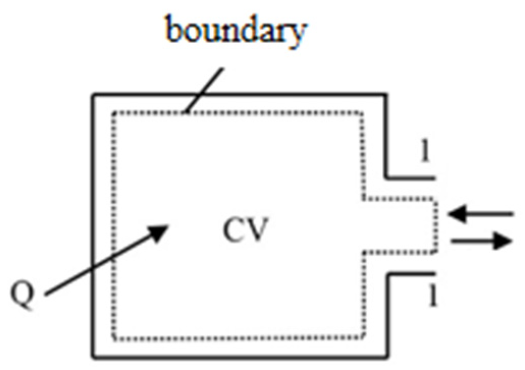
The mathematical model of energy-saving circuit has been established; because the energy-saving efficiency is expressed in the form of ratio, it can be expressed indirectly by comparing the air consumption of the system.

4.2. Experimental Condition Design

The selected cylinder models from SMC Company are MDBL32-150Z, MDBL32-100Z, and MDBL32-50Z. Different displacement ratios are obtained by combining different cylinders. When the supply pressure is 0.3 MPa, different cylinder combinations and strokes are shown in Table 1.
In Table 1, I to VI are the combination ratio codes of primary and secondary cylinders with different stroke ratios; x represents the stroke number of the primary cylinder and y represents the stroke number of the secondary cylinder. In the combination of I, III, and V, the pneumatic strain energy accumulator recovers the compressed air discharged from the operation of the larger stroke cylinder to supply air to the smaller stroke cylinder. In this case, the operation stroke of the primary cylinder is greater than that of the secondary cylinder. In the combination of II, IV, and VI, the pneumatic strain energy accumulator recovers the compressed air discharged from the operation of the smaller stroke cylinder to supply air to the larger stroke cylinder. In this case, the primary cylinder operates multiple strokes, and the operation stroke of the secondary cylinder is greater than or equal to that of the primary cylinder.
In the energy-saving system, after the primary and secondary cylinders complete one stroke respectively, there is no residual air in type V and VI combined pneumatic strain energy accumulator; that is, the exhausted air from the recovered primary cylinder is just enough to supply the complete stroke for the secondary cylinder. This situation is an ideal case for exhaust recovery and energy saving with a strain energy accumulator. For types I, II, III, and IV, there is residual air in the pneumatic strain energy accumulator. Although this part of the air is recovered, it cannot be fully utilized. In order to fully recover the air discharged from the operation of the primary cylinder during the next operation, this part of residual air needs to be discharged through the quick exhaust valve installed at the air inlet of the accumulator, which will cause second energy waste.

4.3. Energy-Saving Efficiency Analysis

For the above energy-saving system, first run 20 cycles to weaken the influence of rubber airbag Mullins effect [
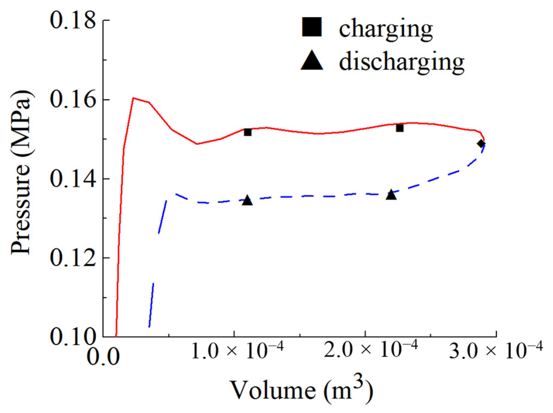
16]. Then run 10 complete cycles to determine the air consumption of the whole energy-saving system through the amount of air entering the primary cylinder. The air consumption of primary and secondary cylinders under the benchmark system is shown in Table 2 and Table 3, which are measured under the air supply pressure of 0.158 MPa and 0.113 MPa for a complete stroke. According to Table 1, the average air consumption with various types of systems (with different cylinder combinations) is shown in Table 4.
This part studies the efficiency of energy loss with the pneumatic strain energy accumulator; the air consumption can be used as an indirect expression of energy loss, and its ratio is consistent. Based on Formula (9), the energy-saving efficiency of the system under different working conditions can be calculated according to the data from Table 2, Table 3 and Table 4. The energy-saving efficiency of the energy-saving circuit based on the combination of different cylinder stroke ratios in Table 1 is shown in Table 5. The residual air ratio means the percentage of residual air in the accumulator compared to the total recovered air from the primary cylinder after finishing the motion stroke of the secondary cylinder.
From Table 5, it can be seen that the energy-saving efficiency in systems I, III, and V is lower than that of types II, IV, and VI. This is because the primary cylinder with a large stroke needs to overcome the backpressure for a long time and consume more compressed air. At the same time, when the energy-saving device recovers the compressed air discharged to supply air to the smaller stroke secondary cylinder, the work done by the expansion energy will cause the secondary cylinder to run additional strokes. Under the condition of recovering the same energy, the smaller stroke secondary cylinder will run more stroke, while for the large stroke secondary cylinder, the work done by the expansion energy is not enough to make it run a completed stroke.
Comparing the systems VI, IV, and II, with three smaller stroke preliminary cylinders and larger stroke secondary cylinders, it can be seen that the energy-saving efficiency of system VI increases significantly because the air recovered by pneumatic strain energy accumulator is fully utilized. However, for systems IV and II, the energy recovered by the accumulator is not fully utilized after the corresponding stroke is completed. The remaining compressed air is discharged into the atmosphere through the quick exhaust valve, resulting in compressed air re-waste. From the above analysis, it can be seen that when the pneumatic strain energy accumulator is applied to the pneumatic system for exhausted air recovery and energy saving, the ideal circuit combination is that the compressed air recovered by the accumulator from the upstream pneumatic actuator is fully supplied to the downstream pneumatic actuator as much as possible. This result further illustrates the design and calculation necessity for the accumulator size in Section 2.2, which was neglected in reference [12].

4.4. System Operation Stability Analysis

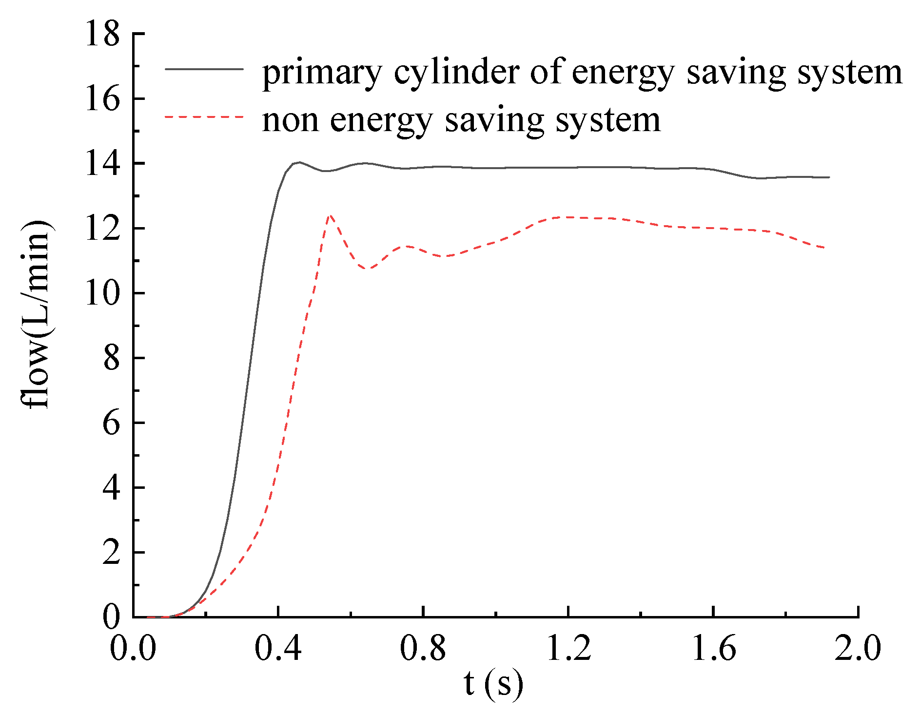
Although the additional pneumatic accumulator will improve the energy efficiency of a pneumatic system, when the pneumatic strain energy accumulator is connected to the exhaust end of the cylinder for compressed air recovery, it will inevitably produce back pressure, which will affect the cylinder running speed and motion stability. In order to study the stability characteristics of pneumatic system, the concept of volatility is introduced. By comparing the volatility of the system, the effect of pneumatic strain energy accumulator on the operation stability of the system is studied. This section analyzes the change of airflow into the cylinder when the main cylinder of the two systems extends the stroke and then estimates the influence of pneumatic strain energy accumulator on the system operation stability, which was neglected in the reference [12]. The fluctuation rate of intake airflow of a primary cylinder of the energy-saving system and reference system is shown in Table 6. The change of intake flow of the primary cylinder with a stroke of 200 mm under the operation of the two systems is shown in Figure 9.
It can be seen from Table 6 and Figure 9 that under the air supply pressure of 0.3 MPa, the inlet flow fluctuation rate of the primary cylinder of different combinations of energy-saving systems is significantly lower than that of the primary cylinder of non-energy-saving systems, indicating that the application of pneumatic strain energy accumulator to the exhaust end can not only improve the stability of cylinder operation but also play a buffer role.
It is worth noting that to ensure that the two systems have equivalent output force, the energy-saving system with a strain energy accumulator needs higher air supply pressure, which makes the air compressor need to produce higher pressure compressed air, so it needs to consume more power. Moreover, although the accumulator can provide stable expansion pressure and contraction pressure, the acquisition of this pressure needs a time process. That is to say, at the end of the accumulator deflating stage, there may be too low of a pressure to drive the movement of the secondary cylinder. Therefore, a certain size redundancy should be considered in the accumulator design.

5. Conclusions

In this paper, an energy-saving circuit with exhaust recovery based on a strain energy accumulator with constant pressure energy storage and discharge is proposed, and the system energy-saving efficiency model is established. Firstly, the size of the airbag and rigid shield and the maximum energy storage capacity of the device are determined. Then the loop energy-saving mathematical model is established using air consumption. Finally, a test bed is built to verify the energy-saving efficiency. The main conclusions are as follows:
(1)
Due to the additional strain energy accumulator, under given different stroke ratio and air supply pressure, the energy-saving system can recover the compressed air discharged from the primary cylinder to supply air to the secondary cylinder, which improves energy efficiency. The variation range of energy-saving efficiency is 21.1–54.1%, respectively. Results show that applying a pneumatic strain energy accumulator to an exhaust recovery system for compressed air energy saving has a good energy-saving effect.
(2)
Residual air in the accumulator has a negative impact on energy-saving efficiency. In practical application, the recovered pressure energy of the pneumatic strain energy accumulator and the pressure energy consumed by secondary components should be matched as much as possible to reduce the generation of residual air.
(3)
Under the air supply pressure of 0.3 MPa, the inlet flow fluctuation rates of the primary cylinder of the energy-saving system with different cylinder combinations are 2.45%, 2.66%, 2.25%, and 1.91%, respectively, while the inlet flow fluctuation rates of the primary cylinder of the benchmark system are 6.78%, 5.37%, 5.53%, and 4.69%, respectively. It is concluded that applying a pneumatic strain energy accumulator for exhaust recovery and energy saving can improve the stability of cylinder operation.
The research of this paper has a good energy-saving effect for traditional pneumatic systems. However, the accumulator is not ready for practical application. The next step will be to arrange case studies with a real system to see the actual energy savings. Furthermore, the existing accumulator only produces a low supply pressure, about 0.1 MPa; research in the future needs to use better hyperelastic materials or structures to achieve new accumulators.

Author Contributions

H.D. carried out coring operations and description. W.L., X.B. and W.X. conducted laboratory experimental studies. All authors have read and agreed to the published version of the manuscript.

Funding

This research was funded by the National Natural Science Foundation of China (52075065) and the Fundamental Research Funds for the Central Universities of China (3132019352).

Institutional Review Board Statement

Not applicable.

Informed Consent Statement

Not applicable.

Data Availability Statement

All the data generated or analyzed during this study are fully available in the manuscript.

Conflicts of Interest

The authors declare they have no competing interest.

References

  1. May, G.; Stahl, B.; Taisch, M.; Kiritsis, D. Energy management in manufacturing: From literature review to a conceptual framework. J. Clean. Prod. 2017, 167, 1464–1489. [Google Scholar] [CrossRef]
  2. Yang, A.; Pu, J.; Wong, C.; Moore, P. By-pass valve control to improve energy efficiency of pneumatic drive system. Control Eng. Pract. 2009, 17, 623–628. [Google Scholar] [CrossRef]
  3. Šešlija, D.; Cajetinac, S.; Blagojevic, V.; Šulc, J. Application of pulse width modulation and by-pass valve control for increasing energy efficiency of pneumatic actuator system. Proc. Inst. Mech. Eng. Part I J. Syst. Control Eng. 2018, 232, 1314–1324. [Google Scholar] [CrossRef]
  4. Du, H.; Hu, C.; Xiong, W.; Jiang, Z.; Wang, L. Energy optimization of pneumatic actuating systems using expansion energy and exhaust recycling. J. Clean. Prod. 2020, 254, 119983. [Google Scholar] [CrossRef]
  5. Gibson, T.J.; Barth, E.J. Design, Model, and Experimental Validation of a Pneumatic Boost Converter. J. Dyn. Syst. Meas. Control 2018, 141, 011004. [Google Scholar] [CrossRef]
  6. Li, T.C.; Wu, H.W.; Kuo, M.J. A Study of Gas Economizing Pneumatic Cylinder. J. Phys. Conf. Ser. 2006, 48, 1227–1232. [Google Scholar] [CrossRef]
  7. Leszczynski, J.; Grybos, D. Compensation for the complexity and over-scaling in industrial pneumatic systems by the accumulation and reuse of exhaust air. Appl. Energy 2019, 239, 1130–1141. [Google Scholar] [CrossRef]
  8. Elija, M.; Relji, V.; Elija, D.; Dudi, S.; Jovanovi, Z. Reuse of exhausted air from multi-actuator pneumatic control systems. Actuators 2021, 10, 125. [Google Scholar] [CrossRef]
  9. Aneke, M.; Wang, M. Energy storage technologies and real life applications—A state of the art review. Appl. Energy 2016, 179, 350–377. [Google Scholar] [CrossRef] [Green Version]
  10. Van de Ven James, D. Constant pressure hydraulic energy storage through a variable area piston hydraulic accumulator. Appl. Energy 2013, 105, 262–270. [Google Scholar] [CrossRef]
  11. Wang, H.; Tong, Z.; Dong, X.; Xiong, W.; Ting, D.S.-K.; Carriveau, R.; Wang, Z. Design and energy saving analysis of a novel isobaric compressed air storage device in pneumatic systems. J. Energy Storage 2021, 38, 102614. [Google Scholar] [CrossRef]
  12. Cummins, J.J.; Nash, C.; Thomas, S.; Justice, A.; Mahadevan, S.; Adams, D.E.; Barth, E.J. Energy conservation in industrial pneumatics: A state model for predicting energetic savings using a novel pneumatic strain energy accumulator. Appl. Energy 2017, 198, 239–249. [Google Scholar] [CrossRef]
  13. Du, H.; Xiong, W.; Jiang, Z.; Li, Q.; Wang, L. Energy efficiency control of pneumatic actuator systems through nonlinear dynamic optimization. J. Clean. Prod. 2018, 184, 511–519. [Google Scholar] [CrossRef]
  14. Blagojevic, V.; Seslija, D.; Dudic, S.; Randjelovic, S. Energy Efficiency of Pneumatic Cylinder Control with Different Levels of Compressed Air Pressure and Clamping Cartridge. Energies 2020, 13, 3711. [Google Scholar] [CrossRef]
  15. Dudić, S.; Reljić, V.; Šešlija, D.; Dakić, N.; Blagojević, V. Improving Energy Efficiency of Flexible Pneumatic Systems. Energies 2021, 14, 1819. [Google Scholar] [CrossRef]
  16. Diani, J.; Fayolle, B.; Gilormini, P. A review on the Mullins effect. Eur. Polym. J. 2009, 45, 601–612. [Google Scholar] [CrossRef] [Green Version]
Figure 1. Designed pneumatic strain energy accumulator.
Sustainability 14 03535 g001
Figure 2. Pneumatic strain energy accumulator charging and discharging pressure volume curve.
Sustainability 14 03535 g002
Figure 3. The inflating process of rubber airbag, (a) bubbles appear, (b) bubbles expand along the axial direction, (c) expansion complete.
Sustainability 14 03535 g003
Figure 4. Open ended thermal system.
Sustainability 14 03535 g004
Figure 5. Isothermal expansion model of constant mass gas.
Sustainability 14 03535 g005
Figure 6. Pneumatic energy-saving circuit with pneumatic strain energy accumulator. 1—Throttle valve, 2—Flow sensor, 3—Three position five-way solenoid valve, 4—Primary cylinder, 5—Throttle valve, 6—Quick exhaust valve, 7—Pressure sensor, 8—Accumulator, 9—Three position five-way solenoid valve, 10—Secondary cylinder, 11, 12—Muffler, 13—Air compressor, 14—Pressure reducing valve.
Sustainability 14 03535 g006
Figure 7. Piston movements (an advance and a return) for each cylinder in the system configuration.
Sustainability 14 03535 g007
Figure 8. Energy-saving circuit test bench. 1—Throttle valve, 2—Flow sensor, 3—Three position five-way solenoid valve, 4—Primary cylinder, 5—Throttle valve, 6—Quick exhaust valve, 7—Pressure sensor, 8—Accumulator, 9—Three position five-way solenoid valve, 10—Secondary cylinder.
Sustainability 14 03535 g008
Figure 9. Variation law of intake in extension stroke of primary cylinder of two systems under 0.3 MPa air supply pressure.
Sustainability 14 03535 g009
Table 1. Cylinder combination and stroke ratio.
Primary CylinderSecondary CylinderStroke RatioSystem Code
100501:2I
501002:1II
150501:3III
501502:1IV
200501:5V
502004:2VI
Table 2. Average air consumption of the primary cylinder under benchmark system.
Cylinder Diameter (mm)Average Air Consumption (L)
2000.524
1500.369
1000.251
500.124
Table 3. Average air consumption of the secondary cylinder under benchmark system.
Cylinder Diameter (mm)Average Air Consumption (L)
2000.469
1500.335
1000.235
500.111
Table 4. Average air consumption with various types of systems.
System CodeStroke RatioAverage Air Consumption (L)
I1:20.381
II2:10.348
III1:30.555
IV2:10.352
V1:50.786
VI4:20.685
Table 5. Energy-saving efficiency and residual air ratio of different cylinder combinations.
System CodeEnergy Efficiency (%)Residual Air Ratio (%)
I21.125.8
II26.246.1
III21.623.4
IV40.317.1
V27.80
VI54.10
Table 6. Intake air flow fluctuation rate of master cylinder of energy-saving system and benchmark system.
Cylinder CombinationVolatility (%)
Energy-Saving SystemBenchmark System
100:502.456.78
50:1002.665.37
150:502.255.53
200:501.914.69
Publisher’s Note: MDPI stays neutral with regard to jurisdictional claims in published maps and institutional affiliations.

