Article

Investigation on Characteristics and Prevention of Rockburst in a Deep Hard and Soft Compound Stratum Tunnel Excavated Using TBM

1
College of Energy and Mining Engineering, Shandong University of Science and Technology, Qingdao 266590, China
2
Shandong Provincial Key Laboratory of Civil Engineering Disaster Prevention and Mitigation, Shandong University of Science and Technology, Qingdao 266590, China
3
School of Civil and Resource Engineering, University of Science and Technology Beijing, Beijing 100083, China
*
Author to whom correspondence should be addressed.
Sustainability 2022, 14(6), 3190; https://doi.org/10.3390/su14063190
Submission received: 18 February 2022 / Revised: 2 March 2022 / Accepted: 6 March 2022 / Published: 8 March 2022

Abstract

:
Rockburst disasters frequently occur in deep tunnels excavated by TBM (tunnel boring machine) under complex geological conditions in western China. Using FLAC3D, the characterization of a three-dimensional numerical model of a compound stratum tunnel excavated by TBM is conducted, based on a water transport project in Shanxi Province. Then, the characteristics of rockburst in deep hard and soft compound stratum tunnels excavated by TBM are revealed, and the energy criteria of the rockburst considering the rock brittleness are proposed. In addition, the prevention and control method of drilling pressure relief for rockburst has been investigated. Results show that: (i) the rockburst risk of compound stratum tunnel excavated using TBM is mainly in the upper-hard rock part, while there is no rockburst risk in the soft rock part; (ii) after the excavation of the tunnel, slight rockburst risk occurs first in the hard rock area of the tunnel vault, and then the rockburst risk gradually rises to the strong level at 7 m behind the working face, indicating the hysteresis of strong rockburst; (iii) the rockburst in the vault of the rock surrounding the compound stratum tunnel has the effect of forming the deepest area, gradually narrowing to both sides, showing a “V” shape, and the occurrence of rockburst may not be completed at one time; (iiii) borehole pressure relief can significantly reduce the rockburst risk of surrounding rock in a tunnel. The larger the borehole diameter and depth, the better the effect of rockburst prevention. In addition, the effect of borehole diameter is more significant than depth. The research results provide guiding references for the prevention and control of similar rockburst disasters in underground engineering.

1. Introduction

With the in-depth implementation of China’s “Western Development” and “One Belt and One Road” strategies, resource mines, water conservancy structures, and traffic tunnels are gradually being transferred to western China [1], which has a topography of high mountains and deep valleys. In this region, the stratum structure is variable due to the significant burial depth and the effect of regional tectonic activities over multiple periods; thus, the soft and hard strata appear alternately. Compared with the central and eastern regions, the sharp in situ stress environment and composite stratum structure are essential characteristics [2]. Rockburst occasionally occurs in TBM construction of deep tunnels in China, resulting in severe equipment damage, construction delay, and significant economic and property losses [3,4,5,6]. The diversion tunnel of Jinping II Hydropower Station, Qinling tunnel of Han-Ji-Wei River Diversion Project, and Zhongtianshan Tunnel are some places where this type of incident has occurred. During TBM construction, rockburst disasters with various characteristics occur several times, causing severe equipment damage, construction delays, and considerable economic and property losses.
Rockbursts in TBM construction tunnels have several characteristics, such as uncertainty, hysteresis, and massive damage, which creates obstacles to predicting and controlling the rockburst mechanism [7,8]. To investigate the related characteristics in depth, domestic and foreign scholars have carried out research work on rockburst in tunnel TBM construction. Xie et al. [9] stated that TBM tunnelling generates a lesser disturbance to the surrounding rock at the excavation boundary, ensures better integrity, and leads to the smoother releasing of surrounding rock strain energy; however, it should be noted that despite all this, due to its higher storage capacity and accumulation of surface surrounding rock strain energy, it easily induces rockburst damage. Wu et al. [10] investigated the diversion tunnel of Jinping II Hydroelectric Power Plant through microseismic monitoring and numerical simulation and found that it has a lithology of thick, dense, fine crystal marble noise, and the local joint development is in the good surrounding rock. For related tunnels, the initiation of rockburst under tunnel TBM excavation has mainly occurred at the tunnel vault and arch shoulder and gradually propagated to the deeper part of the surrounding rock. In another study performed by Chen et al. [11], an acoustic emission test was performed on the selected sites of the #1 test tunnel (referred to as 2-1 test tunnel) of #2 Hengtong Tunnel of Jinping II Hydropower Station. The overlying rock is about 1850 m thick, and the lithology is t-gray layered medium-coarse marble with relatively developed joints and cracks. Results obtained from a field acoustic emission test showed that the fracture damage of the surrounding rock under TBM construction was found in the most critical situation at 3 m after the palm face, and the damage of the surrounding rock has a certain hysteresis. Jiang et al. [12] proposed using the radial gradient of the elastic strain energy density of surrounding rock to predict the location of rockburst, according to the energy criterion of rockburst in TBM construction established by the authors based on the energy principle of rockburst. To reduce the risk of rock explosion in TBM construction of deeply buried tunnels, some scholars [13] have suggested that a combined excavation process consisting of the drill-and-blast method for tunnel guidance and TBM boring under high-stress conditions could be effective; hence, a series of measures were proposed to prevent and control the rock explosion. At present, there are several rock burst prevention and control methods, including drilling and pressure relief, as well as blasting [14,15,16]. However, the step-by-step excavation method of pre-guided cavern undoubtedly leads to an increment in the number of perturbations of the surrounding rock, which easily induces the generation of shear damage due to the high stress surrounding the rock and thus raises the risk of rock explosion [17].
The majority of the research outlined above concentrates on rockbursts in TBM construction for single hard rock strata; however, few studies have been performed on the rockburst characteristics and preventative measures for TBM construction in composite strata. Due to composite strata’s particular stratigraphic structure and stress environment, the characteristics of rock explosion differ; thus, prevention and control approaches are reasonably different than those in single hard rock strata. Thus, the destructive nature and frequency of rock explosions during deep-tunnel TBM construction would be aggravated. Consequently, in the current paper, theoretical analysis and numerical simulation methods were applied to reveal the characteristics of rockbursts in TBM construction tunnels in deep soft and hard composite strata by taking as background a water transmission project in Shanxi. Moreover, to provide a reference for the prevention and control of rockburst disasters in tunnel TBM construction under similar conditions, methods of unloading and preventing rockbursts in boreholes were developed.

2. Engineering Geology of the Research Area

2.1. Engineering Background

Located in the research area, Shanxi Province, the water transport project includes the trunk line, the east trunk line, the west trunk line, and each water supply branch line; all of the #3 tunnel entrances are located approximately 450 m below the Tianguya Reservoir in Xingxian County on the left bank of Lanyi River, and the exit is located on the left bank of Beichuan River, about 3.6 km south of Dawu Town in Fangshan County. The tunnel is divided into three TBM sections. The main tunnel of the TBM-2 section was obtained via TBM excavation, with a total length of 20.7 km, a maximum buried depth of 590 m, a diameter of 4.9 m, and an inner diameter of 4.3 m after the completion of segment support. The main hole is formed using Robbins dual-shield TBM, consisting of front and middle telescopic shields and tail shields.

2.2. Formation Profile

During the process of TBM, the strata through which the main hole of the TBM-2 section of the total dry #3 tunnel passed are Cambrian, Ordovician tuff, dolomite, marl and mudstone, Swire boundary striped diorite hornblende, and unequal grain black cloud plagioclase gneiss. Among these, the rocks surrounding the tuff, dolomite, quartzite, hornblende, and gneiss section are hard or medium-hard rocks, and the geological classification of the surrounding rocks is type Ⅲ, while the surrounding rocks of the marl and mudstone section are soft rocks, and the engineering geological classification of the surrounding rocks is type Ⅳ or type Ⅴ. Due to the influence of orogenic movement and fold structure, the lithologic characteristics of the main tunnel in the TBM-2 section of the #3 tunnel are characterized by a typical TBM construction of soft and hard composite stratum.

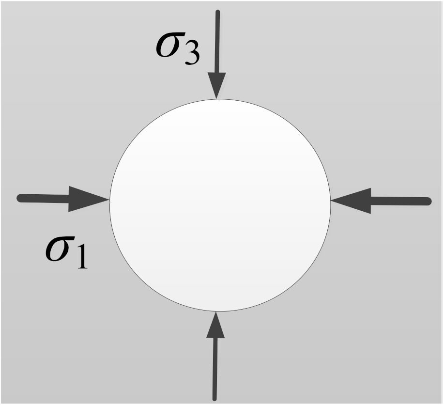
2.3. Distribution of In Situ Stress

The results of the on-site ground stress test and reversal calculation [18] about the research area showed the following: horizontal tectonic stress was dominant along the main stem #3 tunnel, and the maximum horizontal principal stress direction was N82°E–N86°E. This ground stress direction was perpendicular to the tunnel axis direction and was in the most unfavorable direction for the tunnel’s surrounding rock stability. The direction of ground stress on the tunnel cross section is shown in Figure 1. As a result of the regression analysis to obtain the principal stresses, the maximum principal stress σ1 was calculated as 21.16 MPa, the intermediate principal stress σ2 as 17.72 MPa, and the minimum principal σ3 stress as 15.6 MPa at the buried depth of the diversion tunnel, about 600 m.

3. Tunnel Numerical Model Creation

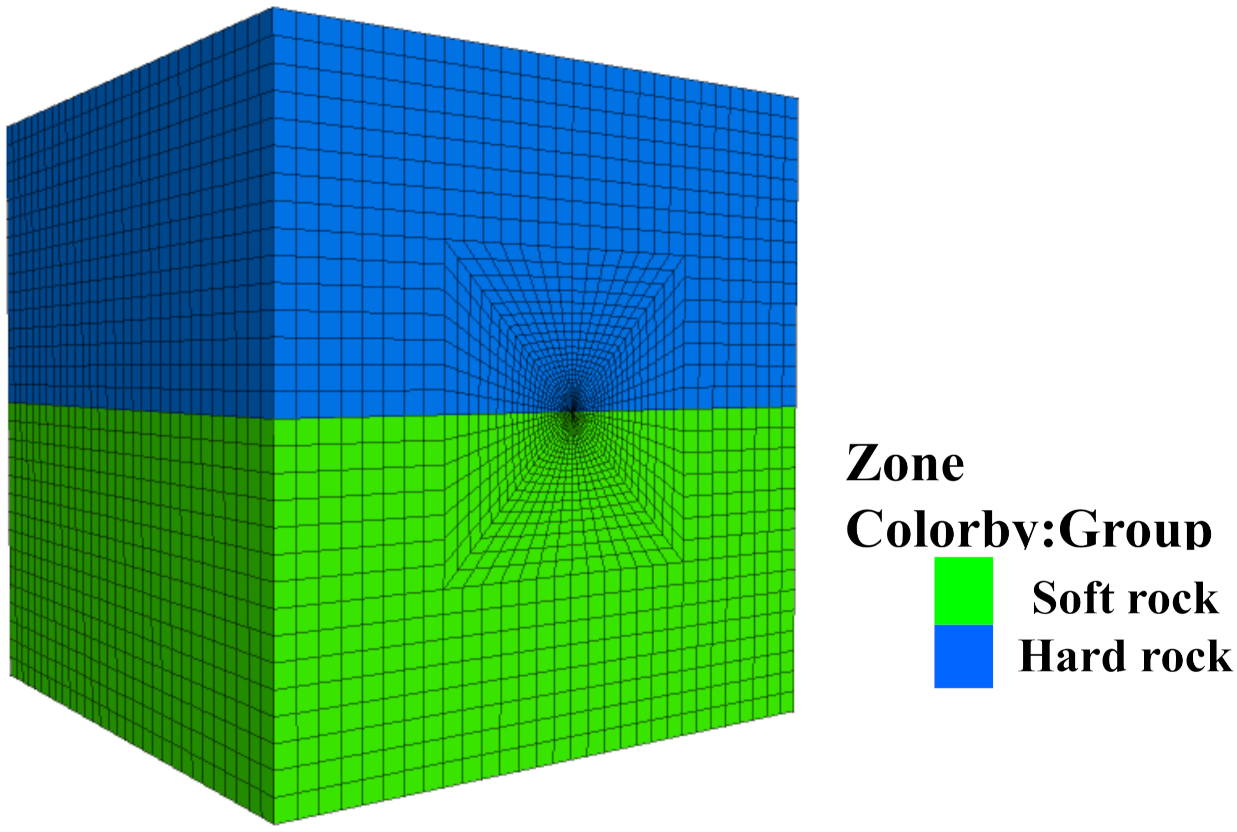
3.1. Model Establishment

Based on the engineering background and geological conditions mentioned above, the three-dimensional numerical calculation model was created with the help of FLAC3D software. To facilitate the comparative analysis of the computational results, the model was simplified by considering the typical upper-hard and lower-soft composite stratigraphic structure, as shown in Figure 2. The tunnel section was circular, with a diameter of 5 m. To reduce the model boundary effect, the lengths of the model’s horizontal direction (X) and vertical direction (Z) were taken as 12 times the diameter (i.e., 60 m). In addition, the longitudinal (Y) direction is taken as 60 m. The boundaries of the model in all directions (left, right, front, back, and bottom) were constraints, which fixed their displacements. In addition, the upper boundary of the model was free. Considering the results of ground stress regression analysis, the horizontal x-direction of the model was the maximum principal stress direction. The axial direction of the tunnel (i.e., the y-direction of the model) was the intermediate principal stress direction, and the vertical z-direction of the model was the minimum principal stress direction. The loads applied in the x-, y-, z-directions were 21.16 MPa, 17.72 MPa, and 15.60 MPa, respectively. The hard surrounding rock of the simulated tunnel section was gneiss, and the weak surrounding rock was marl. Physical and mechanical parameters of rocks obtained from laboratory tests are shown in Table 1.

3.2. TBM Construction and Simulation Process

In order to simulate the construction process with TBM, as shown in Figure 3, simulation of the TBM body self-weight, rolling blade, and shield were implemented in the model [12,19].
In terms of construction principle, TBM is a continuous mechanical excavation, which causes less disturbance to the surrounding rock. With the gentle excavation initiation, ground stress adjustment process, and slow stress release on the TBM boring excavation boundary, the surrounding rock stress-strain curve has a good continuity [20,21]. In terms of construction characteristics, the hob on the cutter during TBM excavation breaks the rock with a minimal infill for uninterrupted continuous excavation. There is no pause in TBM excavation except for particular circumstances, such as equipment maintenance, repair, and cutter replacement downtime. A common method used in current numerical modeling studies is to divide the continuous excavation of TBM into small excavation steps. However, the calculation time-step between excavation steps is often challenging to determine. This method’s model forms the time-step continuity with high accuracy. In addition, the overall continuity and the degree of overall continuity depend on the size of the network partition.
In the numerical simulation, both excavation steps are calculated to be balanced, and there is a large pause in the simulation of the TBM forward movement, which does not reflect the continuity of the TBM excavation process well [22]. R. Hasanpour [23] pointed out that although the explicit time-step solution method in FLAC3D does not reflect the time-related stress-strain relationship with high accuracy, the method of gradually releasing the unbalanced force can effectively simulate the influence of time factors on the excavation process. To ensure that we were simulating the actual process of TBM excavation with maximum accuracy with the model used in the study, two major principles were proposed to be followed in the simulation calculation [24]: (1) the model grid size along the TBM excavation direction should be as small as possible but optimized so that it does not consume too many time steps; (2) the stress release of surrounding rock caused by excavation should be controlled, and the balance cannot be calculated between every two excavation steps.
Based on this, the surrounding rock stress-release rate control method employed in the numerical calculation process of the current study is as follows: (i) one step is calculated after each excavation cycle is completed; (ii) after that, at the current excavation boundary, the maximum unbalanced force on the surface node of the surrounding rock is extracted and multiplied by the difference between the stress release coefficient and 1.0; (iii) the resultant value is then applied as a reverse load to the surface nodes of the surrounding rock of the excavation boundary and calculated to balance. The key benefit of this approach is that there is no need to set the number of calculation steps between two excavation steps; only the stress release coefficient of the surrounding rock is adjusted between two excavation steps. Furthermore, a stress release coefficient of 0.875 can be used to describe the ongoing process of TBM excavation accurately [23,25].

3.3. Constitutive Model Selection

The selection of the appropriate structural model has a significant impact on the simulation results. In this context, the constructive model reflects rock materials’ strength and deformation properties in the most realistic way. In order to obtain the most realistic results, the elastic-plastic damage generation model [26] based on the Mogi–Coulomb criterion was adopted, and the yield function of the model was used as follows:
f ( σ m , 2 , J 2 , D ) = 6 3 J 2 b σ m , 2 ( 1 D ) a
where J 2 is the second invariant of deviatoric stress; σm,2 is the average effective normal stress on the shear plane; D is the damage variable; and a and b are material parameters related to rock mechanical properties, respectively.
Jiang et al. [26] obtained the relationship between the damage variation and the equivalent strain index through true triaxial testing, dividing the rock compression process into two stages, non-destructive and damaged. Additionally, they introduced the damage threshold, and set up the evolution equation of the damage variable, as shown below in Equations (2) and (3):
D = 0 0 < ε e q ε e q o β 1 exp η ( ε e q ε e q o ) ε e q o < ε e q
ε e q = 1 2 ( ε 1 ε 2 ) 2 + ( ε 2 ε 3 ) 2 + ( ε 3 ε 1 ) 2
where β is the residual strength coefficient; η is the positive proportional coefficient, which can be obtained from the test; ε e q is the von Mises equivalent strain; and ε e q o is the damage threshold represented by the equivalent strain.
The model was constructed based on the Mogi–Coulomb criterion, as the joint effect of plasticity and damage of rock materials was taken into account. In this way, it can more accurately describe the failure conditions and deformation characteristics of rock under true triaxial stress and is more suitable for deep underground engineering analysis under a three-dimensional stress state. The model parameter values are shown in Table 2.
In order to verify the rationality of the model in the current study, the failure characteristics of surrounding rock under TBM construction in composite strata were simulated. The results obtained with the Mohr–Coulomb model were compared with the surrounding rock section 2 m behind the face of the tunnel face, as shown in Figure 4.
As can be seen from Figure 4, the Mohr–Coulomb model does not consider the effect of intermediate principal stress, so the calculated plastic zone range was wide. The extent of the plastic zone on the tunnel sidewall was about 2.02 m. Based on the Mogi–Coulomb criterion, the plastic zone of the surrounding rock was about 1.50 m. However, the actual field measurement of the tunnel left side wall fissure distribution depth was about 1.48 m. Therefore, it can be said that the calculation results of the elastoplastic damage constitutive model used in the current study reflected the real failure of surrounding rock more accurately.

4. Rockburst Energy Criterion Based on Rock Brittleness Index

Rockburst is of great harmfulness. A slight rockburst will result in the rock falling off in a flaky shape, and there will be no ejection. When a major rock burst occurs, it will feel like an earthquake with a magnitude of 4.6, and felt intensity is as high as 8 degrees. It will pose a serious threat of damage to the buildings in the immediate vicinity, due to the felt ground motion and loud noise, and will threaten the safety of the major projects still in progress and the lives of the relevant construction personnel. To discriminate the conditions under which rockburst will occur in the surrounding rock of underground engineering projects and the degree of damage it may cause, scholars at home and abroad have carried out a large number of relevant studies and investigations and have put forward many rockburst criteria and intensity classification standards from different angles, as shown in Table 3.
Except for the elastic energy index criterion and the Tao Zhenyu criterion, all of the above criteria are expressed in terms of tangential stress or maximum tangential stress, which requires coordinate transformation when using numerical calculation software to simulate rockburst risk; therefore, they are inconvenient to apply. Obtaining the elastic energy index criterion requires laboratory tests on rock, and it is measured using the integral area of the stress-strain curve under loading and unloading conditions. The rockburst discrimination result is greatly affected by test conditions and human factors. In point of fact, the occurrence of rockburst is closely related to the three-dimensional stress state of rock. The Tao Zhenyu rockburst criterion has a certain one-sidedness based on maximum principal stress, which is also proved by the rockburst engineering examples in China. With the development of rockburst energy theory, many scholars have introduced some energy criteria of rockburst based on analysis of the energy transformation mechanism in rock deformation and failure, resulting in a good application effect.
Based upon the analysis of the energy accumulation mode of surrounding rock during TBM construction, Jiang et al. [26] proposed a rockburst energy criterion for TBM construction, expressed as follows in Equation (4):
U e U 0 > 1
where U e is the stored elastic strain energy density of surrounding rock, and U 0 is the ultimate elastic strain energy density of surrounding rock; these can be expressed as the following Equations (5) and (6), respectively:
U e = σ 1 2 + σ 2 2 + σ 3 2 2 ν ( σ 1 σ 2 + σ 1 σ 3 + σ 2 σ 3 ) 2 E
U 0 = σ c 3 2 E ( σ 1 σ 3 )
The above energy criterion is satisfied with the occurrence rockburst when the internal accumulation of the surrounding rock reaches the surface energy required to destroy the surrounding rock, at the critical value U 0 —that is, when the elastic strain energy U e can be released. However, the above rockburst discriminatory index does not consider the critical influence of rock brittleness characteristics on the rockburst occurring in TBM construction in composite strata tunnels. For this reason, the above criterion is modified to propose a rockburst energy criterion Cr, taking into account these indicators, as follows below in Equation (7):
C r = σ c σ t U e U 0
where σc/σt indicates the brittleness coefficient of the rock formation, a characteristic characterization distinction for hard, brittle rocks. Some scholars [28] have used the brittleness coefficient for discrimination of rock explosion and classification of intensity class as follows: <15.0, no rock explosion; 15.0 to 18.0, minor rock explosion; 18.0 to 22.0, moderate rock explosion; >22.0, strong rock explosion.
Combined with the existing rockburst criterion, the probability of boundary indexes of different factors reaching the maximum value was simultaneously small. For convenience of application, the boundary indexes and intensity classification of rockburst criterion Cr are shown in Table 4.

5. Simulation Results of Rockburst Feature

The program used in the study was modified via FISH language with consideration of Cr (i.e., rockburst energy criterion) as the brittleness characteristics of rock strata, according to Equation (7), to obtain the distribution and evolution law of the Cr value of a tunnel’s surrounding rock under TBM construction conditions, as shown in Figure 5. The positive value of the distance between the measuring point and the palm surface indicates the measuring point is positioned in front of the palm surface; the negative value indicates the measuring point is positioned behind the palm surface (Figure 5).
The conclusions that can be obtained from Figure 5 are as follows:
(1)
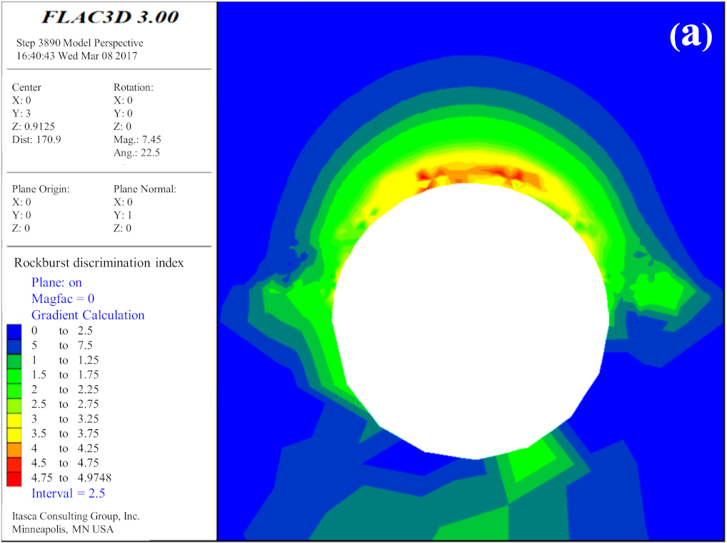
The hard rock part of the tunnel’s upper part with composite strata had rockburst risk under TBM excavation; however, the soft rock part had no rockburst risk due to large deformation and release of most of the energy.
(2)
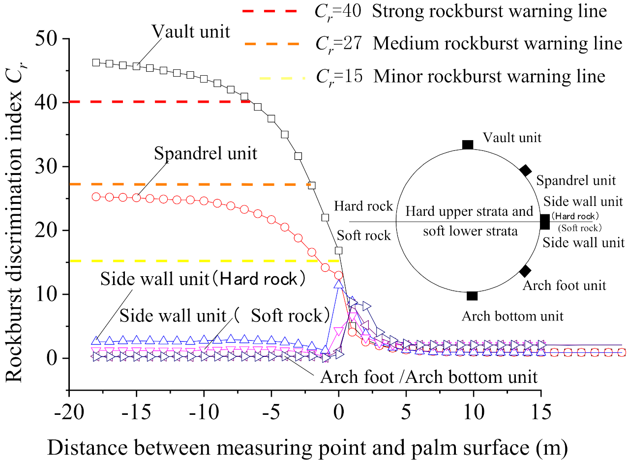
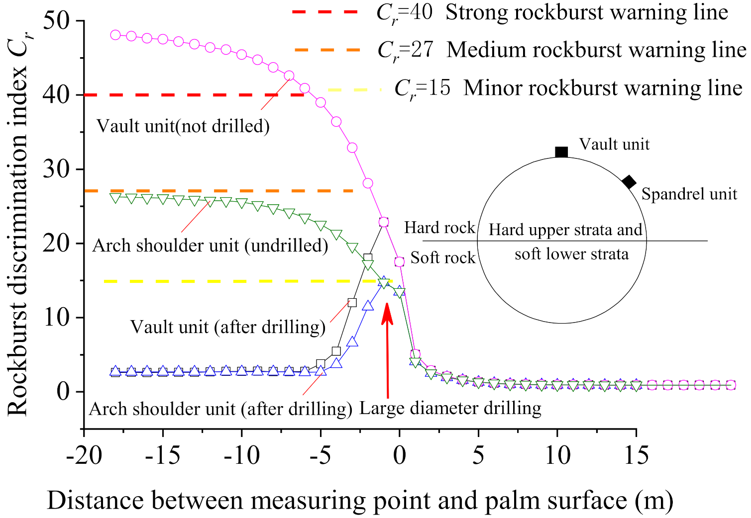
During excavation of the palm face up to a region situated before the measurement point, the Cr value of the surrounding rock changed according to the same law. In this situation, the palm face TBM excavation was maintained up to the monitoring section, and the Cr value of the surrounding rock at different locations in the hard rock part showed various change patterns, which were as follows: For surrounding rock at the sidewall of the tunnel, in the case of the face being excavated up to the monitoring section (the distance between the measuring point and the face was 0 m), the Cr value reached a maximum of 11.4, and then began to decrease and remained at a lower level. Throughout the entire TBM excavation process, the Cr value of the surrounding rock of the sidewall was always less than 15; thus, rockburst risk did not occur. Towards the surrounding rock at the vault and arch shoulder of the tunnel, in the case of excavation of the arch face up to the monitoring section, the Cr value of the surrounding rock at the vault increased to 16.8, causing a slight risk of rockburst. For a related case, the Cr value of the surrounding rock at the arch shoulder was 12.9; therefore, the possibility of rockburst did not occur. When the palm face was pushed through the monitoring section of 2 m, the Cr value of the surrounding rock at the arch shoulder exhibited an increment to 16.6, with a slight risk of rock explosion. When the Cr value of the surrounding rock of the vault increased to 27, a medium risk of rockburst occurred. Afterward, the palm face was pushed through the monitoring section of 7 m; the Cr value of the surrounding rock’s arch part exceeded 40 and gradually stabilized, and the risk of rockburst became strong. Similarly, the Cr value of the surrounding rock at the arch shoulder exhibited an increment to 24, and then gradually stabilized; the slight rockburst risk was continued.
According to Equation (7), the area with rockburst criterion Cr value exceeding 15 was regarded as the rockburst zone. The distribution characteristics of the rockburst zone during tunnel TBM construction were obtained, as shown in Figure 6.
As can be clearly seen from Figure 6, rockburst areas were mainly concentrated in hard rock; as TBM progressed, the rockburst area gradually propagated from the shallow part of the initial vault of the deep and arch shoulder position. In the section where the distance between surrounding rock and the face of the palm was about 10 m, the depth of the surrounding rockburst pits did not increase; the maximum development depth of the rockburst area was located at the vault, at about 0.88 m. The depth of the rockburst pits at both sides of the arch shoulders gradually decreased, and the burst pits generally had a “V” shape, which was consistent with a rockburst situation that occurred in actual TBM tunnel engineering [30,31,32]. Moreover, the occurrence of a rockburst may not end at once; the risk of another rockburst exists, unless corresponding measures are taken in the area where the rockburst has occurred.

6. Borehole Pressure Relief Prevention of Rockburst

The prevention and control of rockburst are essential in avoiding the brittle dynamic instability of surrounding rock, which can reduce the strength and brittleness of surrounding rock, improve the stress state of surrounding rock, and promote the favorable transformation of the failure mode of surrounding rock [33]. In this context, borehole pressure relief is a widely used active prevention and control measure for rockbursts in coal mines around the globe. Through manual drilling in the surrounding rock, the integrity of the surrounding rock is destroyed, and the mechanical properties of the surrounding rock are weakened. Thereby, the surrounding rock within a certain range around the borehole is plastically damaged, and elastic strain energy is released. Consequently, the high stress of surrounding rock is transferred; thus, rockburst risk is eliminated.
To analyze the treatment effect of borehole pressure relief on rockburst of a tunnel constructed by TBM in a composite stratum, a drilling pressure relief model of surrounding rock was established based on the abovementioned model. The variation rules of surrounding rock stress and rockburst criterion Cr values were simulated and analyzed before and after borehole pressure relief.

6.1. Pressure Relief Model of Borehole

The evaluations were performed using the automatic generation method of complex FLAC3D model based on the ANSYS platform [34]. In the first stage, the model was established, and meshes were divided in ANSYS software; afterward, the established model was imported into FLAC3D software by using an FLAC3D-ANSYS interface program. The drilling pressure relief model is shown in Figure 7. The size and boundary conditions of the model were the same as those of the model given in Figure 2. For the model’s realization of the TBM excavation process, refer to Section 2.2 above, and refer to Table 2 for model material parameters.

6.2. Rockburst Treatment Effect of Borehole Pressure Relief

The Cr value distribution of the rockburst criterion before and after the drilling pressure relief was obtained by simulation, according to Equation (7). The section 2 m behind the palm face was analyzed, as shown in Figure 8. The variation rule of surrounding rock Cr values at the vault and arch shoulder of hard rock in composite strata was monitored before and after drilling pressure relief (Figure 9).
The conclusions that can be obtained from Figure 8 and Figure 9 are as follows:
(1)
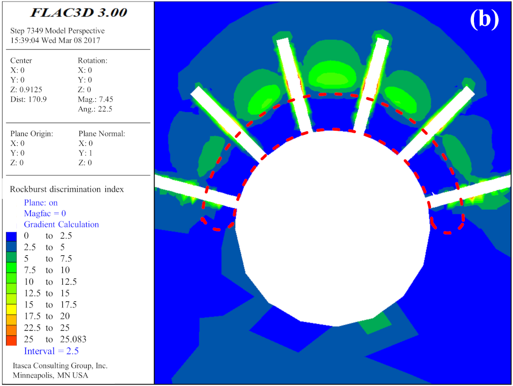
The Cr value of the tunnel surrounding the rock vault and arch shoulder immediately dropped below 3.0 after the borehole pressure relief; furthermore, the Cr value no longer increased as the TBM progressed compared with the non-implemented borehole pressure relief.
(2)
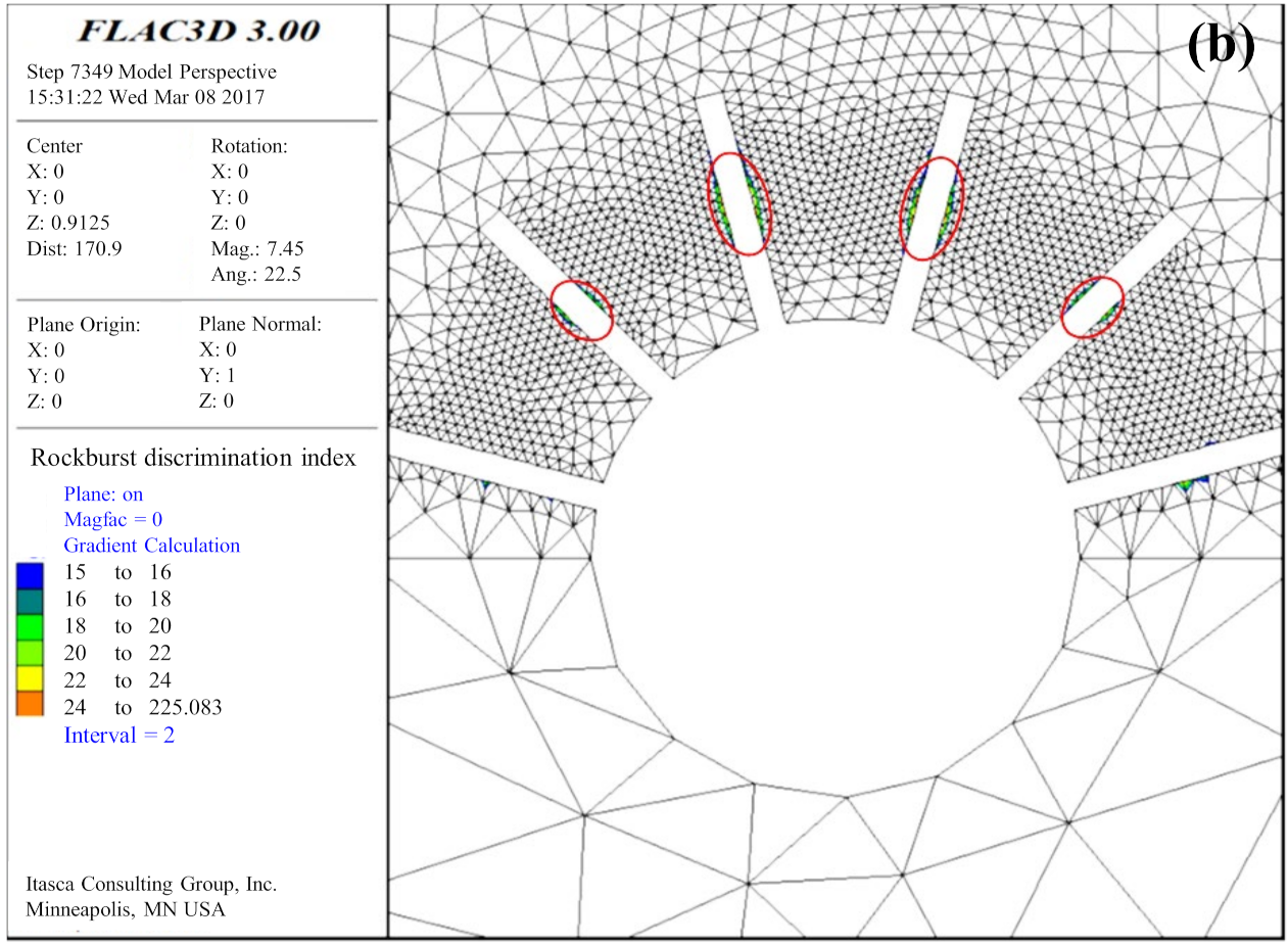
After pressure relief, the maximum value of Cr in surrounding rock exhibited a decrement to about 25 and was mainly located around the hole wall at the section of 1.5 m deep in the borehole. The main reason for this situation was the elastic state of the rock mass around the deeper section of the hole wall with a certain degree of stress concentration.
(3)
After drilling and depressurizing the hard rock at the upper part of the tunnel that was 2 m behind the tunnel face, a certain depth of weakened zone was formed in the shallow region of surrounding rock; hence, the Cr value of the surrounding rock within the weakened zone decreased significantly. As shown in Figure 8b, in the area that the red dashed circle encloses, the Cr value of the surrounding rock in the weakened zone was considerably less than the rockburst threshold value of 15, and the rockburst risk was significantly reduced.
Figure 10 shows the distribution of the rockburst zone before and after pressure relief by drilling in the surrounding rock of the tunnel. Without drilling treatment, the rockburst zone of the tunnel vault and arch shoulder was more extensive, and the Cr value of surrounding rock at the vault could reach 49, indicating serious rockburst risk. After pressure relief, the shallow rockburst zone of the tunnel’s surrounding rock disappeared completely. The deep rockburst zone of the tunnel became quite small, mainly distributed around the deeper region of the hole wall, as shown in Figure 10b. According to the numerical simulation results, for the TBM construction tunnel in composite strata, the pressure relief treatment of some hard rock in the surrounding rock can effectively reduce and eliminate rockburst danger.

6.3. Influence of Borehole Parameters on Rockburst Prevention and Control Effect

By changing the diameter and depth of the borehole pressure relief, the variation rule of the depth of the pressure-relief-weakening zone of the surrounding rock was simulated and analyzed, as shown in Figure 11.
Figure 11 shows that by increasing the borehole diameter from 200 mm to 400 mm, the depth of the weakened zone increased by nearly 200%; as the borehole depth increased from 2.5 m to 5 m, the depth of the weakened zone increased by 40%. The intersection point of the curve is the optimal parameter, that is, the drilling depth is 4 m, and the drilling diameter is 300 mm. Consequently, as borehole diameter and depth increased, the depth of the shallow weakening zone in the surrounding rock gradually increased; thus, the rockburst prevention and control mechanism were improved. Compared with the borehole depth, the impact of the borehole diameter is more dominant on prevention and control of the rockburst.

7. Conclusions

In this study, the characteristics and prevention of rockburst in a deep hard and soft compound stratum tunnel excavated using TBM were investigated. The specific conclusions of the research are as follows:
(1)
The rockburst risk of the compound stratum tunnel excavated by TBM mainly occurred in the upper-hard rock part, while in the soft rock part, rockburst risk did not occur. After the excavation of the tunnel, the first slight rockburst risk occurred in the hard rock area of the tunnel vault. Subsequently, the rockburst intensity at the vault and arch shoulder positions increased progressively, resulting in the occurrence of a severe rockburst risk in the vault position at 7 m behind the working face, which indicated the hysteresis of strong rockburst.
(2)
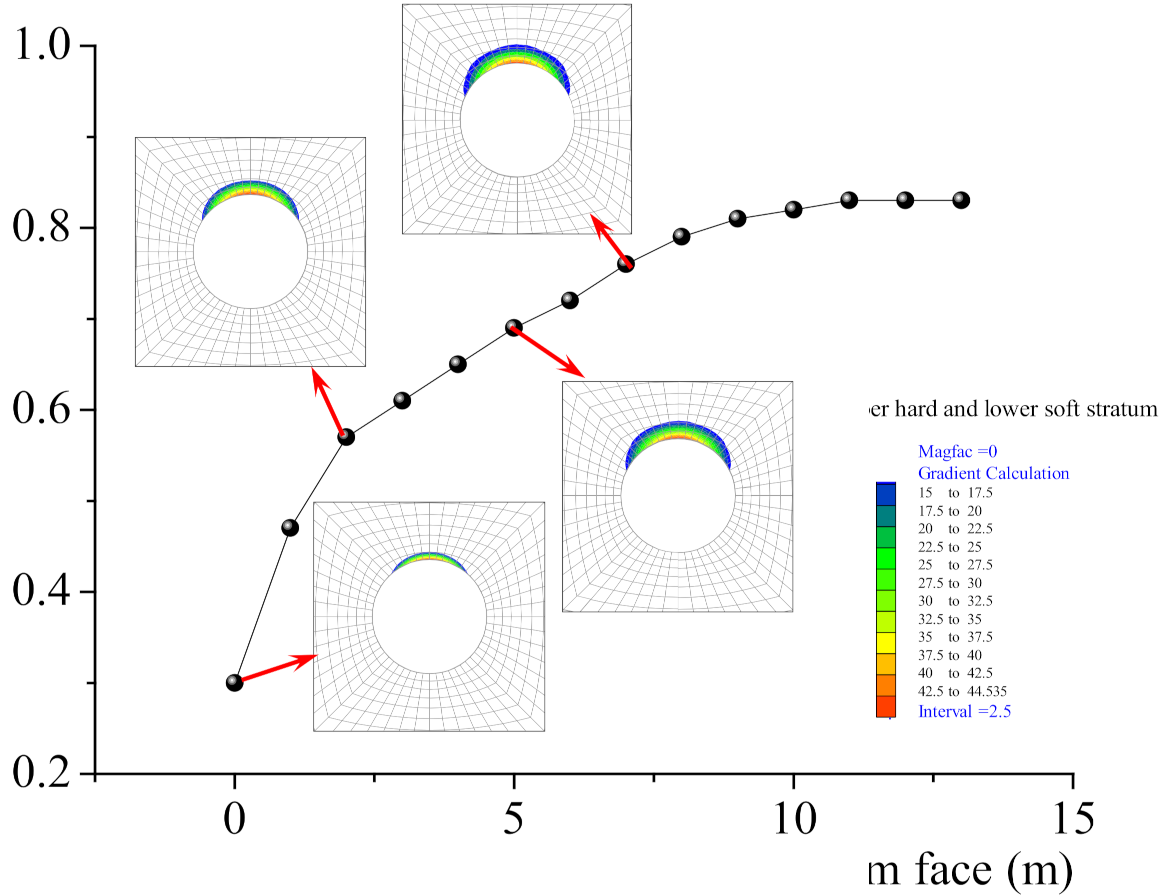
The rockburst area at the vault of the surrounding rock was the deepest, with a depth of about 0.88 m. The blast crater’s depth progressively decreased on both sides of the arch shoulder, forming a “V” shape.
(3)
After the hard rock part of the composite strata, the tunnel was relieved by drilling. A certain depth of weakening zone was formed in the shallow part of the surrounding rock, which significantly reduced the rockburst risk of the surrounding rock. Compared with the depth of the borehole, the diameter of the borehole has a more significant impact on the rockburst prevention effect.
These research results provide guiding references for the prevention and control of similar rockburst disasters in underground engineering.

Author Contributions

Conceptualization, W.L. and B.J.; methodology, M.D.; software, B.J.; validation, S.G. and H.J.; formal analysis, M.D.; writing—original draft preparation, B.J.; writing—review and editing, S.G.; formal analysis and investigation. All authors have read and agreed to the published version of the manuscript.

Funding

This research is founded by the Natural Science Foundation of China (52004144) and Natural Science Foundation of Shandong Province, China (ZR2019BEE001).

Institutional Review Board Statement

Not applicable.

Informed Consent Statement

Not applicable.

Conflicts of Interest

The authors declare no conflict of interest.

References

  1. Hong, K.R. State-of-art and prospect of tunnels and underground works in China. Tunn. Constr. 2015, 35, 95–107. [Google Scholar]
  2. Liu, Q.S.; Huang, X.; Liu, J.P.; Pan, Y.U. Interaction and safety control between TBM and deep mixed ground. J. China Coal Soc. 2015, 40, 1213–1224. [Google Scholar] [CrossRef]
  3. Zhou, J.J.; Yang, Z.X. Discussion on key issues of TBM construction for long and deep tunnels. Rock Soil Mech. 2014, 35, 299–305. [Google Scholar] [CrossRef]
  4. Feng, Q.; Jin, J.C.; Zhang, S.; Liu, W.W.; Yang, X.X.; Li, W.T. Study on a damage model and uniaxial compression simulation method of frozen–thawed rock. Rock Mech. Rock Eng. 2021, 55, 187–211. [Google Scholar] [CrossRef]
  5. Qian, Q.H. Definition, mechanism, classification and quantitative forecast model for rockburst and pressure. Rock Soil Mech. 2014, 35, 1–6. [Google Scholar] [CrossRef]
  6. Ma, T.H.; Tang, C.A. Rockburst Analysis, Monitoring and Control; Dalian University of Technology Press: Dalian, China, 2014. [Google Scholar]
  7. Zhang, Z.T.; Chen, Z.; Chen, B.R.; Jiang, H.L.; Cui, H.; Gao, Z.L. TBM construction method in the large overburden and intensive rock burst zone. J. China Coal Soc. 2011, 36, 431–435. [Google Scholar] [CrossRef]
  8. Y, Y. Rockburst mechanism of deep buried high ground stress hard rock tunnel. Constr. Technol. 2013, 42, 237–239. [Google Scholar]
  9. Guo, J.Q.; Zhao, Q.; Wang, J.B.; Zhang, J. Rockburst prediction based on elastic strain energy. Chin. J. Rock Mech. Eng. 2015, 34, 1786–1795. [Google Scholar] [CrossRef]
  10. Wu, S.Y.; Zhou, J.F.; Chen, B.R.; Huang, M.B. Effect of excavation schemes of TBM on risk of rock burst of long tunnel at Jinping II Hydropower Station. Chin. J. Rock Mech. Eng. 2015, 34, 728–734. [Google Scholar] [CrossRef]
  11. Chen, B.R.; Feng, X.T.; Xiao, Y.X.; Ming, H.J.; Zhang, C.S.; Jing, H.; Chu, W. Acoustic emission test on damage evolution of surrounding rock in deep-buried tunnel during TBM excavation. Chin. J. Rock Mech. Eng. 2010, 29, 1562–1569. [Google Scholar]
  12. Jiang, B.Y.; Wang, L.G.; Gu, S.T.; Zhang, X.D.; Li, W.S. Study on rockburst mechanism of TBM excavation for deep tunnel based on energy principle. J. Min. Saf. Eng. 2017, 34, 1103–1109. [Google Scholar] [CrossRef]
  13. Fang, D.M.; Liu, N.; Zhang, C.Q.; Cu, W.J.; Chen, X.J. Rockburst risk control for large diameter TBM boring in high geostress region. Chin. J. Rock Mech. Eng. 2013, 32, 2100–2107. [Google Scholar]
  14. Li, L.P.; Jia, C.; Sun, Z.Z. Research status and development trend of major engineering disaster prevention and control technology in deep underground. J. Cent. South Univ. (Sci. Technol.) 2021, 52, 2539–2556. [Google Scholar]
  15. Wang, Q.W.; Ju, N.P.; Du, L.L. Research on rockburst prediction and engineering measures of long and deep-lying tunnels. Hydrogeol. Eng. Geol. 2016, 43, 88–94. [Google Scholar]
  16. Liang, D.Z. Prevention and Control Measures for Rock Burst During Excavation of Underground Cavern Under High Geo-stress. Sichuan Water Power 2021, 40, 32–35. [Google Scholar]
  17. Zhang, J.J.; Fu, B.J. Rockburst and its criteria and control. Chin. J. Rock Mech. Eng. 2008, 27, 2034–2042. [Google Scholar]
  18. Lin, F. Study on Surrounding Rock Stability of TBM Construction Process for Long Distance Water Conveyance Tunnel; Zhejiang University of Technology: Hangzhou, China, 2013. [Google Scholar]
  19. Liu, H.; Liu, Q.S.; Tang, X.H.; Luo, C.Y.; Wan, W.K.; Chen, L. Identification of the interaction loads between TBM shield and surrounding rock. Rock Soil Mech. 2019, 40, 4946–4954. [Google Scholar]
  20. Huang, X.; Liu, Q.S.; Liu, K.D.; Kang, Y.S.; Liu, X.W. Laboratory study of deformation and failure of soft rock for deep ground tunnelling with TBM. Chin. J. Rock Mech. Eng. 2015, 34, 76–92. [Google Scholar] [CrossRef]
  21. Liu, L.P.; Wang, X.G.; Jia, Z.X.; Duan, Q.W.; Yu, H.Z.; Liu, B. Analysis of mechanism and characteristic of rockburst in drainage-hole of JinpingⅡ hydropower station. J. Cent. South Univ. (Sci. Technol.) 2011, 42, 3150–3156. [Google Scholar]
  22. Ramoni, M.; Anagnostou, G. The Interaction Between Shield, Ground and Tunnel Support in TBM Tunnelling through Squeezing Ground. Rock Mech. Rock Eng. 2011, 44, 37–61. [Google Scholar] [CrossRef]
  23. Hasanpour, R. Advance numerical simulation of tunnelling by using a double shield TBM. Comput. Geotech. 2014, 57, 37–52. [Google Scholar] [CrossRef]
  24. Cheng, J.L.; Yang, S.Q.; Du, L.K.; Wen, S.; Zhang, J.Y. Three-dimensional numerical simulation on interaction between double-shield TBM and surrounding rock mass in composite ground. Chin. J. Rock Mech. Eng. 2016, 35, 511–523. [Google Scholar] [CrossRef]
  25. Meng, Q.B.; Han, L.J.; Qiao, W.G. Elastic-plastic analysis of the very weakly cemented surrounding rock considering characteristics of strain softening and expansion. J. China Univ. Min. Technol. 2018, 47, 760–767. [Google Scholar]
  26. Jiang, B.Y.; Tan, Y.L.; Wang, L.G.; Gu, S.T.; Dai, H.B. Development and numerical implementation of elastoplastic damage constitutive model for rock based on Mogi-Coulomb criterion. J. China Univ. Min. Technol. 2019, 48, 784–792. [Google Scholar] [CrossRef]
  27. Gao, Y.H.; Feng, X.T.; Zhang, X.W.; Zhou, Y.Y.; Zhang, Y. Generalized crack damage stress thresholds of hard rocks under true triaxial compression. Acta Geotech. 2020, 15, 565–580. [Google Scholar] [CrossRef]
  28. Shang, Y.J.; Zhang, J.J.; Fu, B.J. Analyses of three parameters for strain mode rockburst and expression of rockburst potential. Chin. J. Rock Mech. Eng. 2013, 32, 1520–1527. [Google Scholar]
  29. Tao, Z.Y. Rockburst and its criterion in highly geostressen zone. People’s Yangtze River 1987, 5, 32. [Google Scholar] [CrossRef]
  30. Chen, B.R.; Feng, X.T.; Zeng, X.H.; Xiao, Y.X.; Zhang, Z.T.; Ming, H.J.; Feng, G.L. Real-time microseismic monitoring and its characteristic analysis during TBM tunnelling in deep-buried tunnel. Chin. J. Rock Mech. Eng. 2011, 30, 275–283. [Google Scholar]
  31. Hou, J.; Zhang, C.S.; Shan, Z.G. Rockburst characteristics and the control measures in the deep diversion tunnel of Jinping II hydropower station. Chin. J. Undergr. Space Eng. 2011, 7, 1251–1257. [Google Scholar]
  32. Li, W.S.; Jiang, B.Y.; Gu, S.T.; Yang, X.X.; Faiz, U.A.S. Experimental study on the shear behaviour of grout-infilled specimens and micromechanical properties of grout-rock interface. J. Cent. South Univ. 2021, 2021, 1–14. [Google Scholar]
  33. Jiang, B.Y. Evolution and Control Mechanism of Rockburst Induced by TBM Excavation in Deep Mixed Ground Tunnel; China University of Mining and Technology: Xuzhou, China, 2017. [Google Scholar]
  34. Liao, Q.L.; Zeng, Q.B.; Liu, T.; Lu, S.B.; Hou, Z.S. Automatic model generation of complex geologic body with FLAC3D based on ANSYS platform. Chin. J. Rock Mech. Eng. 2005, 24, 1010–1013. [Google Scholar]
Figure 1. The in situ stress direction of tunnel cross-section.
Sustainability 14 03190 g001
Figure 2. Numerical model of upper-hard and lower-soft stratum.
Sustainability 14 03190 g002
Figure 3. Numerical simulation of TBM excavation: (a) normal force; (b) tangential force; (c) shield; (d) bodyweight.
Sustainability 14 03190 g003
Figure 4. Distribution of plastic zone of TBM tunnel surrounding rock in the compound stratum. (a) Mohr–Coulomb model; (b) elastoplastic damage constitutive model; (c) the detection result of the distribution range of the cracks in the left side wall of the tunnel.
Sustainability 14 03190 g004
Figure 5. Evolution law of rockburst criterion Cr for a tunnel’s surrounding rock during TBM excavation.
Sustainability 14 03190 g005
Figure 6. Evolution law of rockburst pits of surrounding rock during TBM construction.
Sustainability 14 03190 g006
Figure 7. Numerical model of borehole pressure relief.
Sustainability 14 03190 g007
Figure 8. Distribution of rockburst criterion Cr of tunnel surrounding rock after borehole: (a) not drilled; (b) drilling pressure relief with hole diameter of 300 mm and hole depth of 2.5 m.
Sustainability 14 03190 g008aSustainability 14 03190 g008b
Figure 9. Variation law of rockburst criterion Cr of tunnel surrounding rock during TBM excavation after borehole.
Sustainability 14 03190 g009
Figure 10. Distribution of rockburst area of tunnel surrounding rock after borehole: (a) not drilled; (b) drilling pressure relief (hole diameter 300 mm, hole depth 2.5 m).
Sustainability 14 03190 g010aSustainability 14 03190 g010b
Figure 11. Depth variation of tunnel surrounding rock under different borehole parameters.
Sustainability 14 03190 g011
Table 1. Physical and mechanical parameters of rock.
LithologyElastic Modulus
(GPa)
Poisson RatioThe Angle of Internal Friction
(°)
Cohesive Forces
(MPa)
Uniaxial Compressive Strength
(MPa)
Tensile Strength
(MPa)
Gneiss7.50.27385.5784.7
Marl1.50.35241.0121.2
Table 2. Model parameters [18].
Lithology ε e q o ηβ
Gneiss0.01450.8
Marl0.00410.6
Table 3. Rockburst criterion and intensity classification [17,27,28,29].
Rockburst CriterionCountry/
Regional Engineering
Rockburst DiscriminantRockburst Intensity Classification
No RockburstMinor RockburstMedium RockburstStrong Rockburst
E. Hoek methodSouth Africa σ θ max / σ c <0.340.34~0.420.42~0.56>0.70
Russenes criterionNorway σ θ max / σ c <0.20.2~0.30.3~0.55>0.55
Turchaninov criterionXibin Block Mine, Kola Peninsula ( σ θ + σ L ) / σ c <0.30.3~0.50.5~0.8>0.8
Elastic energy index criterionPolish coal mine W e t = Φ s p / Φ s t <22.0~4.9≥5.0
Erlang Mountain highway tunnel criterionChina σ θ / σ c 0.30.3~0.50.5~0.7>0.7
Zhenyu Tao rockburst criterionChina σ c / σ 1 >14.514.5~5.55.5~2.5<2.5
Rockburst potential criterionChina P r b = ( σ θ / σ t ) K V <1.71.7~3.33.3~9.7>9.7
Table 4. Intensity classification of rockburst criterion Cr.
Cr Indicator Value<15.015.0~27.027.0~40.0>40.0
Rockburst intensityNo rockburstMinor rockburstMedium rockburstStrong rockburst
Publisher’s Note: MDPI stays neutral with regard to jurisdictional claims in published maps and institutional affiliations.

