Article

Control Strategies of Hybrid Energy Harvesting—A Survey

Faculty of Electrical Engineering, Czech Technical University in Prague, Technicka 1902/2, CZ-166 27 Praha 6, Czech Republic
*
Author to whom correspondence should be addressed.
Sustainability 2022, 14(24), 16670; https://doi.org/10.3390/su142416670
Submission received: 4 November 2022 / Revised: 3 December 2022 / Accepted: 7 December 2022 / Published: 13 December 2022
(This article belongs to the Special Issue Sustainability of Clean and Accessible Energy)

Abstract

:
In this article, we deal with the problem of Hybrid Energy Harvesting control strategies, while paying attention to their properties and suggesting criteria to assess their suitability for specific energy harvesting techniques, as well as their application in different areas of technology—especially Wireless Sensor Networks and the Internet of Things. Many research works have already been published on the topic of combining resources for Energy Harvesting; nevertheless, a comprehensive review of the control strategies for such systems and a comparison of their most important properties is missing. This is the genesis and the main subject of this article. We have performed a deep research investigation of available resources. We have identified eight different control strategies and defined a set of the most important parameters (including their possible ranges/states) as criteria to be able to compare them. The corresponding sections of this article begin with a general description of the respective strategies and their principles (including generalized schemes), which is followed by specific examples of best practices. The key conclusions of the performed analysis are summarized in a comparison table that allows the readers to make their own conclusions and choices.

1. Introduction

Humanity has come a long way from using energy for satisfying its basic needs to securing a high standard of living. We gradually worked our way up from decentralized small individual energy sources to multi-megawatt ones (e.g., the Kashiwazaki-Kariwa nuclear power plant in Japan that had declared an output power of almost 8 GW and produced 60.3 TWh of electricity per year). Recently, we have been also witnessing the opposite trend—the decentralization of resources, techniques, and technologies—which leads to the reuse of essentially lost (micro-) energy from our environment. The term Energy Harvesting is now commonly used in this context. The limits of this technology are obvious at first glance: sometimes the energy source is sufficient to satisfy the current needs, while at other times it is not. That is why a very interesting superstructure is considered—i.e., a combination of multiple sources for Energy Harvesting technologies. This opens up a lot of space for managing and combining of different energy sources.

1.1. Mankind and Energy

In order to survive, people always needed some kind of energy to be used mainly for heating and cooking. More and more sophisticated forms of energy exploitation led successively to increasing living standards, which, paradoxically, implied higher and higher energy consumption. Over the centuries, mankind has come to the point where relatively cheap energy sources have been almost depleted, and therefore it is necessary to seek alternative ones.

1.2. Ways to Obtain Energy

Of course, it is not possible to “generate” energy, as energy and matter can only be mutually transformed. So, the question is how energy can be transformed from an available form to a required one. For example, the mechanical (potential and/or kinetic) energy of water or wind can be transformed either to the mechanical energy of a millstone, or to another form, e.g., electrical energy. Hereinafter we are going to focus only on the form of energy that can be used to operate electronic devices, i.e., electricity.
Energy harvesting (EH) is usually defined as a process during which the electrical energy needed for the operation of a microdevice is obtained directly from its closest environment so that the considered device does not require an external power supply or frequent replacement of batteries. Such categories typically include wireless sensors, biomedical implants, military monitoring devices, weather stations, etc. Several years ago, we could even observe an attempt to develop a cellphone harvesting energy from radio waves present in the ambient space.
The history of energy harvesting, according to the current definition, begins in 1826, when T. J. Seebeck noticed the formation of an electric current when two metal conductors were connected and their terminals were placed at different temperatures. This discovery was followed E. Becquerel with the photovoltaic effect and M. Faraday with the discovery of electromagnetic induction. The Curie brothers discovered piezoelectricity. All of these inventions play a very important role in future EH technologies. As for the term “harvesting” itself, it first appeared in the literature (in relation to energy) in November 1958 [1].
The main topic of the article is the use of solar energy to power various appliances, such as radio receivers. In general, in the beginnings of EH, the authors focused mainly on the use of solar energy. This is evidenced by the activities of the authors from the end of the 1980s, when the topic of EH began to appear regularly in specialized publications (see Figure 1).
In the field of EH, especially the topics of vibrations (one of the first appearances in the literature was [2] in 1976) and piezoelectricity ([3] in 2001) are gradually being added to the use of solar energy. At about the same time, a description of the use of radio-frequency (RF) resources appeared [4], and subsequently, more and more possibilities opened up.
Modern devices are relatively modest in energy consumption (and the trend is to continue its reducing); however, depending on their functionality, they can require a considerable amount of energy for their continuous operation. It is clear that the demands for this technology will increase, and the use of single energy sources will not be sufficient. Thus, at the beginning of the 21st century, combinations of different technologies began to emerge [5,6]. The techniques and technologies of EH source combinations (hybrid energy harvesting—HEH) are diverse and, in addition, their authors often do not reveal the principles and specific details of the mergers they propose.
Moreover, overview articles (e.g., [7] or [8]) deal mainly with the materials and material nature of EH techniques. The description of applied control algorithms, schemes, and principles of HEH systems to the extent presented by us is still missing in the literature.
Currently, there are several dozens of review articles on EH available. They are very diversified in many respects. Typically, the articles focus on the area of communication between devices and on the respective communication protocols [9,10,11,12,13,14,15,16,17]. In some cases, these are exclusively communication protocols in terms of communication content, while other authors also deal with the security aspects of communication [12,14,18]. Their relation to 5G technologies is a promising trend [11]. The efficiency of communication is addressed in [19]. Article [13] appears to be one of key importance in this area; however, it is focused on the issue of beamforming and on the topics of power transfer and wireless communication.
When the topic of EH is elaborated in more detail, it mostly deals with some narrowly specialized area, for example, with respect to the energy source. RF-based techniques are described in [20,21,22,23]; those based on solar energy are described in [24] and in many other sources. Descriptions of the EH techniques implementation in specific applications are also available. Wireless Sensor Networks (WSN) [16,25,26,27,28,29,30,31,32] or various modifications for the Internet of Things (IoT) [33,34,35,36,37,38], wearable electronics and healthcare applications [37,39,40] predominate here. In the given context, descriptions of the use of EH in the field of automotive technology [41], in the monitoring of airplane components [42], or for use in digital cameras [43] seem to be marginal.
In our opinion, the work closest to ours is [41], which describes the individual energy sources for EH in considerable detail. However, unlike the core of this article, the authors do not focus on the combination of resources, and apply their research to the narrow area of vehicular networks. Article [44] is very important, as it discusses various aspects of the architecture of sensor systems for EH, energy sources, and storage technologies, including examples of applications; in addition, it deals with recharging options and with sensor network design. However, the authors do not consider a hybrid scheme—a combination of different sources and techniques. Another noteworthy article is [45], where the authors deal directly with control strategies, but only the concept of vibration-based EH control (piezoceramics) is elaborated in detail. A relatively older paper [46] from 2013 comes close to the issue we cover. The authors deal with selected HEH control techniques in order to design a plug-and-play architecture with regard to their commercial availability and, of course, with expert knowledge of the state-of-the-art in the year of publishing. In [46], the authors introduce comparisons between the models from the viewpoint of components and capabilities, while our article goes to the system level of the HEH models. As it is a conference paper, the lack of space significantly affected its shape, and therefore, the depth of the description of individual control techniques is not fully in line with today’s criteria for an article. Essential details, such as the description of control techniques (provided by us with respect to the categorization of HEH systems), are not presented in [46].
Based on the abovementioned facts, we can observe the extensive activity of various authors in this area and, on the other hand, the absence of a survey article that would describe and compare the basic principles of applied HEH control strategies. The purpose of this article is not to identify the most suitable one (this is not even possible, due to the huge diversity of technologies and types of resources—or their combinations); its goal is to provide interested professionals with a tool that can be used to formulate their own conclusions concerning the suitability of the considered control strategy for a particular HEH system. This is why this work has been carried out. Our aspiration is to fill the described gap.
In this section (Introduction), important milestones in the history of energy harvesting are listed, followed by the description of the logical transition towards combined (or hybrid) EH sources, i.e., HEH. The rest of the article is organized as follows.
Section 2. Motivation:
  • Briefly outlines the importance of energy harvesting;
  • Combines the energy sources in the modern world of technology.
  • Section 3. Methodology for Hybrid Energy Harvesting Strategies:
  • Summarizes the most important HEH control strategies;
  • Provides generalized schemes;
  • Introduces the existing practical implementations.
  • Section 4. Comparison and Discussion:
  • Details the information that is summarized in the comparison table (see Appendix A);
  • Describes the proposed criteria;
  • Discusses the individual strategies.
  • Section 5. Conclusions:
  • Summarizes the crucial information;
  • Discusses the ways of future research;
  • Discusses the most important challenges.

2. Motivation

Climate change and environmental degradation pose an existential threat to Europe and the whole world. The main risks can be identified in energy production and its related processes. The European Commission activity “Green Agreement for Europe—Striving to become the first climate-neutral continent” [47] is a major attempt to find a solution.
The problem of access to energies is addressed by many other national as well as global institutions, one of them also being the United Nations (see UN Sustainable Development Goal 7: “Ensure access to affordable, reliable, sustainable and modern energy for all” [48]).
Going hand in hand with the current turbulent global political situation, the prices of energies are being pushed up, which also makes all products and services increasingly expensive. This could lead to a true crisis due to “energy poverty”.
Despite this situation, the demand for energies is constantly increasing [49]. This is not only due to the growing world population, but also to other development trends, such as the transition towards Industry 4.0 or IoT, along with Internet Protocol v6 (IPv6). These technologies anticipate huge numbers of devices (e.g., sensors and sensor networks) concurrently accessing the Internet, thus consuming a significant amount of energy.
However, the independently operated devices are independently power-supplied, which logically leads to the designing of techniques that can provide them with energy coming from their local resources (environments).
The solution for the mentioned problems is a system of new techniques and technologies for generating energy known as “Green Energy”. Many research teams deal with these problems. The solution can be seen in harvesting the energy from diversified resources, such as solar, wind, mechanical (vibrations), residual heat, human power, etc. In this respect, we need to utilize the so-called “occasional resources” (this malicious name can be understood positively in the given context), which are, however, not reliable when used independently and exclusively, as their availability and efficiency largely depend on territorial and other aspects. Besides various types of storages, we have to consider the energy flow management and similar techniques. One of the possibilities that has recently been largely discussed consists in “fusion technologies” combining various sources. The main advantage of this approach is that, in the case of a temporary shortage of a specific resource (e.g., solar), the other types (e.g., vibrations) can still be available, thus overcoming the outage. Such fusion, of course, requires a sophisticated management system that is able to evaluate the expected consumption vs. the predicted resource capacities.
Some authors specializing in energy fusion only publish the measurement results and overall performance figures, but not the principles and other know-how behind the specific technologies.
Therefore, we want to summarize the overview of the existing technologies that come into consideration based on different authors’ works within the field of new trends and ideas for energy-combining methods, strategies in energy harvesting, green energy, and sustainability.

3. Methodology for Hybrid Energy Harvesting Strategies

In this section, we provide a description and comparison of different approaches used to combine two or more energy sources for EH. These techniques have been selected as typical ones; however, other options of minor importance can be found in the specialized literature.

3.1. Supplementary Use of Different Energy Sources

The technique of supplementary use of energy sources is based on one energy harvester serving as the main energy resource and one or more energy harvesters supporting the main one by feeding some of the system components (or enhancing the efficiency of the main harvester). The key advantage of this technique is its simple design, which, however, must be a special one in order to meet the requirements of the application and the conditions of the ambient environment.
In the following brief overview, we present some examples of applications that need to supply energy for different parts of the respective system by making use either of different harvesting principles or even of the same one for different branches. Typically, two independent EH techniques are implemented in a single device. However, these systems are not equipped with any kind of sophisticated system capable of managing the utilization of the energy sources in a synergic way.
In [50], the authors used a photovoltaic transducer as the main energy harvester to charge a supercapacitor through a DC–DC converter, while a piezoelectric transducer was used as a secondary harvester to provide energy to the system for its self-start-up (the system consumes more energy when starting up, as the electronics require it). The principle scheme is shown in [50]. The system was based on 13 nm CMOS technology and the peak efficiency was 90.5%.
Another example can be found in [51]. The authors used a thermal generator as the main energy harvester to power a battery-less sensor, and a piezoelectric transducer was used as the secondary harvester to provide the necessary bias for the rectifier circuit required for the thermal generator and some parts of the wireless sensor node.
In these two methods, the energies harvested from the different sources were not combined, and the energy from the secondary one was always used in a specific part of the system, which meant wasting the energy of the secondary harvester.
In [52], the authors used the air flow to increase the efficiency of a thermal generator by 27% and used cooling water to increase the efficiency of the thermal generator by 45%; however, the mechanism of providing the air flow and the cooling water was not explained in detail.
We consider the absence of an energy management system a major drawback of the described techniques. This standpoint is also supported by the fact that newer works have been focusing on possible improvements in this respect, as outlined in the following sections.

3.2. Power ORing

The Power ORing is a power system used in applications where a combination of power from multiple sources is required. Its purpose is to select one power source from several resources or to provide a power architecture with sufficient redundancy. The Power ORing is a solution used not only for power combination, but also for selection and protection when several power sources are used as inputs of the system; it provides protection from hot-plugs, the absence of any single source, failures, or short circuiting.
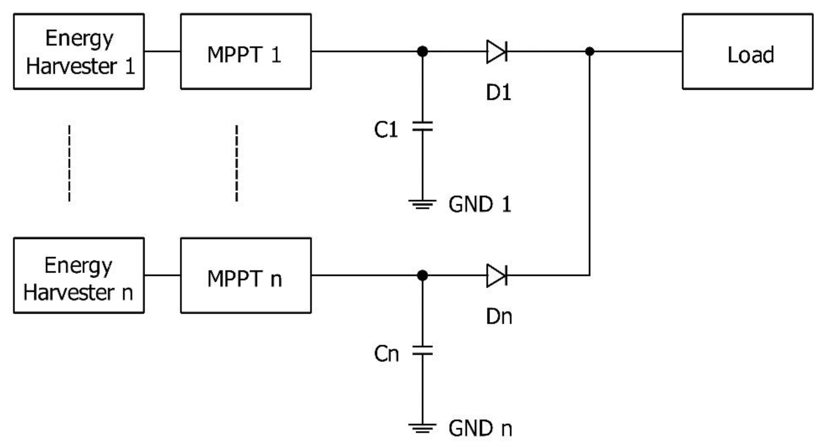
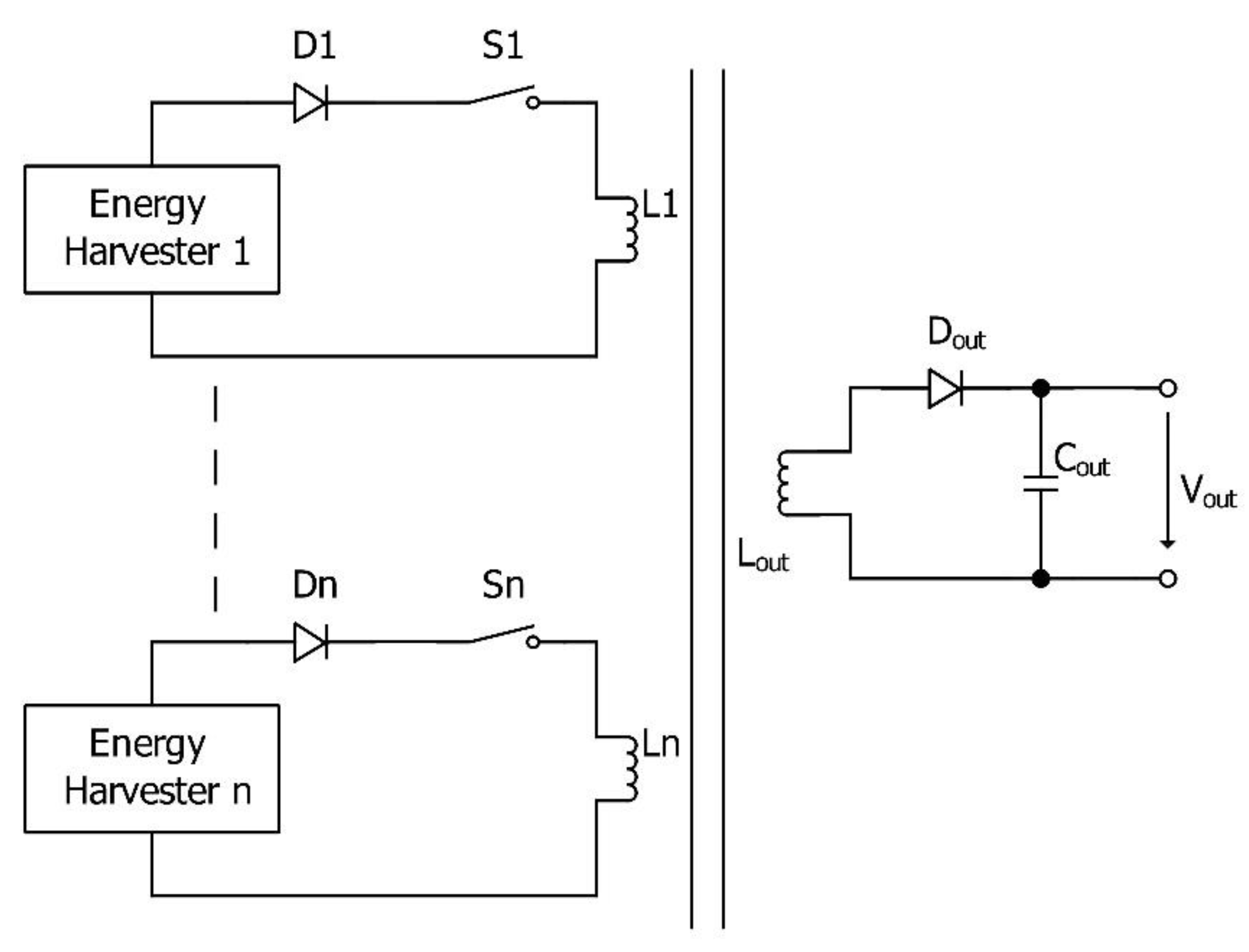
Power ORing topology connects n sources of energy in parallel through conventional diodes, Schottky diode(s), or MOSFET, as shown in Figure 2 (based on [50,51,52]). This topology will provide the isolation of each connected power resource, as well as protection from shunt-connected power resources and other negative factors. This approach guarantees redundancy and reliability of the multisource power system [53].
According to the requirements given by the application and its power supply, the desired electronic elements can be chosen. Each of the electronic elements has its advantages and disadvantages. A conventional diode can be used for protection and isolation of the power resources, but its forward voltage drop is higher than that of a Schottky, while its reverse recovery time and reverse recovery loss are higher.
The Schottky diode is an optimal solution when simplicity of the system in the circuit is required. Its disadvantage consists in not providing the control abilities, so the Power ORing will choose the resource with the highest voltage amplitude; such behavior leads to the wasting of energy from other resources with lower voltage amplitudes. Another disadvantage is the relatively high forward voltage drop (compared to Power MOSFETs), which is inversely proportional to temperature. This leads to additional heat generation. The third disadvantage is represented by the reverse leakage current of the Schottky diode, which increases with temperature; as a result, thermal management is required to avoid the effects of forward voltage drop and reverse leakage current.
Power MOSFETs have a low forward voltage drop compared to Schottky and conventional diodes; also in addition, this setup is fully controllable in terms of switching (on/off) thresholds and speed. Its disadvantage is higher complexity and size of the circuit [54].
Using the Power ORing in multiple energy harvesting applications is very common, because it is considered the simplest and cheapest method. It provides the ability to connect arbitrary energy harvesters in parallel regardless of the nature of the sources. For this purpose, a special interface circuit for each resource is available. It also increases the efficiency by connecting an independent maximum power point tracking (MPPT) for each resource.
Several architectures of the Power ORing are used. In [55], the authors used ORing topology with a simple design to combine the energy from solar, heat, and wind harvesters to charge a supercapacitor, thus reducing the complexity and energy consumption. They added a rectifier circuit in series with the wind harvester to get a DC output and connected the three harvesters using diodes to a step-up module to provide a constant 5.5 V output. The presented design is very simple, but there is no real combining of the harvested energy, because only the harvester with the highest output voltage will be selected to charge the supercapacitor. In addition, in this case, the voltage drop and energy consumption occur on the diode, but the authors do not discuss them.
In order to increase the efficiency in collecting the energy, the authors in [56] used several piezoelectric converters with different frequency responses to extend the harvesting frequency range. They proposed a Power ORing topology with conventional diodes to combine the energy from piezoelectric converters operating at different frequencies and store it in a capacitor to feed a batteryless sensor. The system is cheap and simple, but it wastes energy, due to voltage drops on the diodes. In addition, the energy is gained from the source with the highest voltage amplitude.
In [57], the authors combined the energy from a solar harvester and a wind harvester using a simple diode-based Power ORing topology to charge a supercapacitor, which subsequently charged a rechargeable battery. They used an independent MPPT circuit for each harvester to increase the harvesting efficiency. The proposed circuit is simple; however, its energy consumption is high because of the inclusion of the MPPT circuit. Thus, in the case of insufficient ambient energy, the MPPT circuit will decrease the efficiency of the entire system, because its own energy consumption is higher than the amount of harvested energy.
A combination of energy from thermal and light harvesters using Schottky diodes to create a Power ORing topology was discussed in [58]. The forward voltage drop is low and the circuit is simple, but energy is still wasted when other harvesters have a lower voltage, which is similar to the cases presented hereinbefore.
In [59], the authors proposed a system called the power utility maximizer (PUMA), which is an array of diodes (forming the Power ORing topology) and switches controlled by a control unit. The system is able to combine the energy from several harvesters with the option to implement different control algorithms.
The involvement of the Power ORing will make the system simple, compact, low-cost, and self-synchronized if the number of harvesters is low; however, increasing the number of harvesters will result in higher cost, larger size, and increased energy consumption, due to the use of several MPPT circuits.

3.3. Voltage Level Detection Method

The voltage level detection technique utilizes a controller that manages the switches of the individual harvesters. The controller can use different algorithms and methods based on the applications and the harvester types. The complexity of this technique grows with the number of components in the system. In some cases, the efficiency is affected by the complexity because of the high energy consumption of the system components. The voltage level detection is usually based on comparing the output voltage of the individual harvesters against a given threshold. Some typical examples are provided hereinafter.
In [60], the authors used thermal and RF harvesters to charge the storage device. The power management unit was designed to compare the output voltage level of the thermal harvester and the RF harvester to give the priority to the source with the highest value when both sources were active. In addition, it provided minimum/maximum voltage protection for the storage device, which was a micro battery. CMOS technology was used for integrated circuit (IC) fabrication (0.18 μm, while the area of the micro battery was 30 mm2). The IC contained a power supply manager, battery charger, discharger monitor, and RF converter. The efficiency of the power supply manager and the battery charger was 78% for a charging current of 27 μA. The leakage current of the battery was 12 pA, and the maximum power loss in the battery discharge monitor was 5 nW.
The authors in [61] used solar, thermal, piezoelectric and RF harvesters connected to the load through supercapacitors and PMOS controllable switches. The maximum voltage was selected with respect to the Vmax of the used battery (which was Li-ion). When any supercapacitor of the harvesters reached the Vmax voltage, the controller connected this harvester to the battery until the voltage of its supercapacitor was less than Vmax; then, the controller disconnected this harvester and connected the harvester with a supercapacitor voltage equal to the Vmax.
An energy combiner with three inputs of sources was proposed in [62]. In addition, the number of inputs could be expanded. The design consisted of a digital control unit, comparators, capacitors, resistors and switches to combine the energy based on voltage level detection. The harvested energy was stored temporarily in an individual capacitor for each harvester. The threshold voltage was defined using two resistors. The algorithm implemented in the controller checked if the voltage of the capacitor was higher than the voltage threshold. Then, the corresponding switch connected it to the load. When the voltage of the capacitor dropped below the threshold, the controller checked whether the voltage of the second capacitor was higher than the threshold to connect it to the load, otherwise it checked the voltage level of the third capacitor and repeated the process until it found the input with a capacitor voltage higher than the threshold (and then connected it). The proposed design had an area of 160.155 μm × 177.940 μm (in 65 nm technology). The total power consumption of the combiner was 160 µW with a combining efficiency of 94.67% for one active source, 83.11% for two sources, and 82.91% for three sources.
In [63], the authors designed an energy combiner based on the voltage level detection method, which involved two inputs with integrated maximum power point tracking. Each energy harvester stored the energy in an individual capacitor, and the controller connected the main energy storage device to the branch where the voltage of the capacitor was higher than the voltage threshold. The peak tracking efficiency was 96%, and the power conversion efficiency reached 87.2% for 198 µW of output power and 72% for 981 µW. An optimal charging strategy for a Li-ion battery was analyzed in [64].

3.4. Multiple Input Boost Converter (MIBC)

A boost converter is a DC–DC power converter that steps up the output voltage. It combines the energy from several resources using different techniques based on the specific topology. It is an efficient solution which requires a simple control method, but it is expensive and bulky. The following paragraphs show examples of typical design forms.

3.4.1. Serial Form

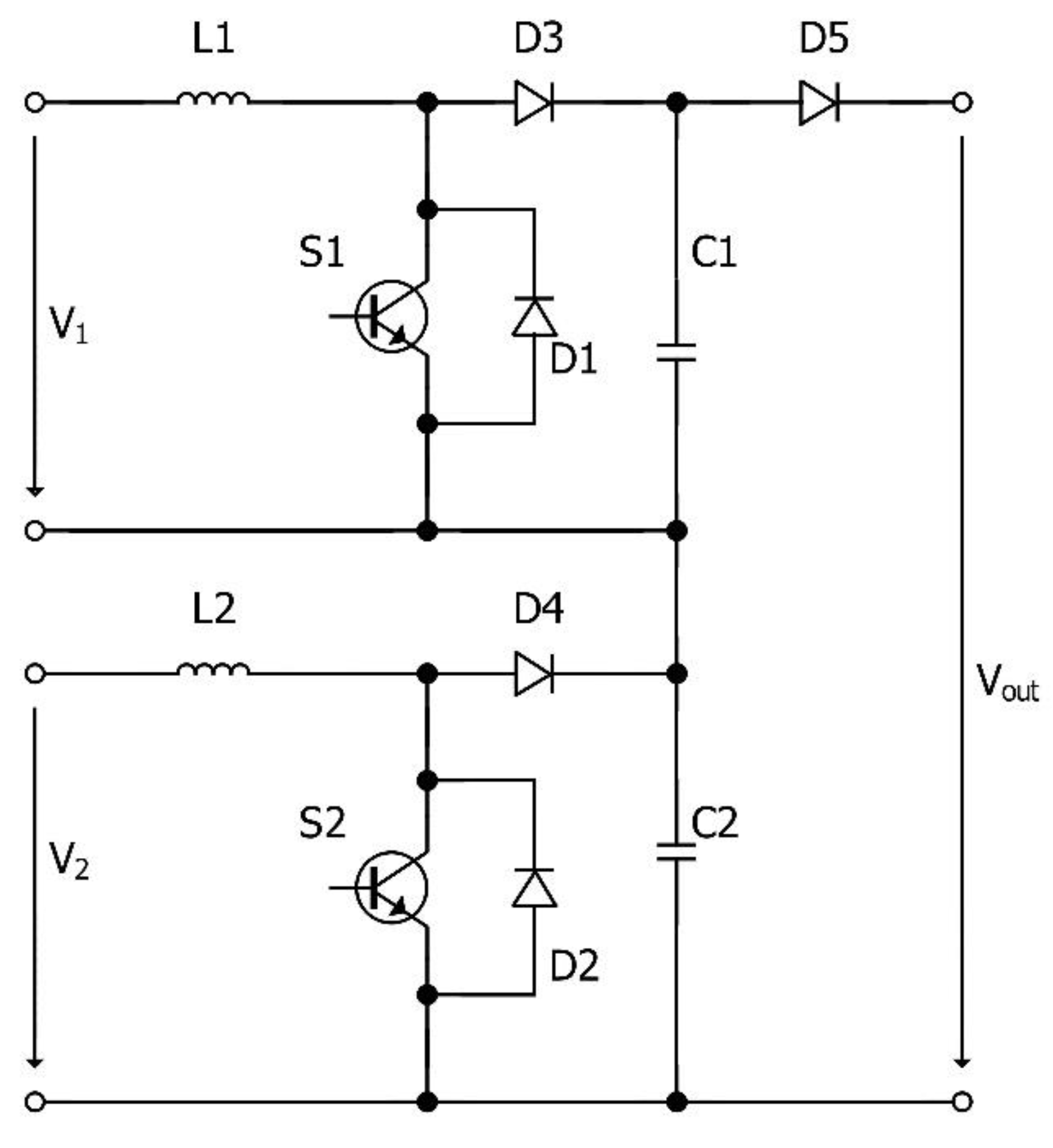
In [65], the authors presented a DC–DC converter topology to combine wind energy and photovoltaic energy by connecting two switching-mode, DC–DC, step-up pulse-width-modulation-controlled (PWM) converters in series. The connection of two step-up stages in series was proposed to comply with the operating characteristics of the wind and photovoltaic harvesters, which produce low voltage values (see Figure 3, based on [65]). They also provided a magnitude of the output voltage equal to the input voltage, thus achieving better switch utilization than the parallel connection. The most important disadvantage of this topology is that voltage drop at one of the sources will bring the output to an unregulated state; this is because maintaining the input voltage variation is an important condition to produce a regulated output in a boost converter.

3.4.2. Magnetic Form

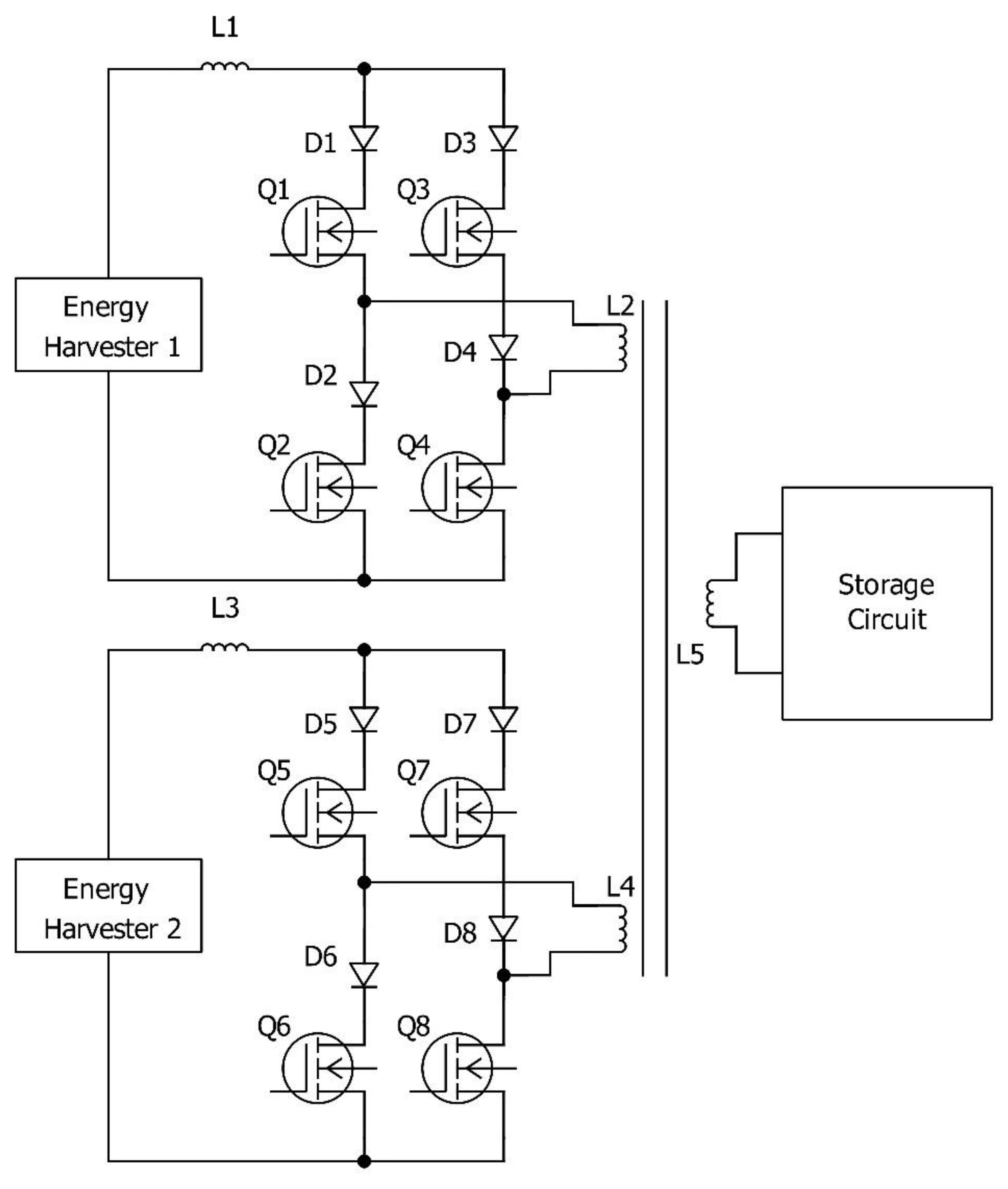
Using a multiple input DC–DC converter to combine the energy from two sources in the magnetic form instead of the electric form was proposed in [66]. The DC–DC converter was based on the flux additivity, and by using the phase-shifted PWM control strategy, the input DC sources in the magnetic form were combined in the magnetic core by adding the produced magnetic flux. This topology (see Figure 4, based on [66]) has several advantages, such as combining the energy from two resources, regardless of the voltage magnitude at the input; furthermore, any input can deliver the energy independently and simultaneously. The disadvantages here include the limitation of the number of input sources and the large size.

3.4.3. Special Design

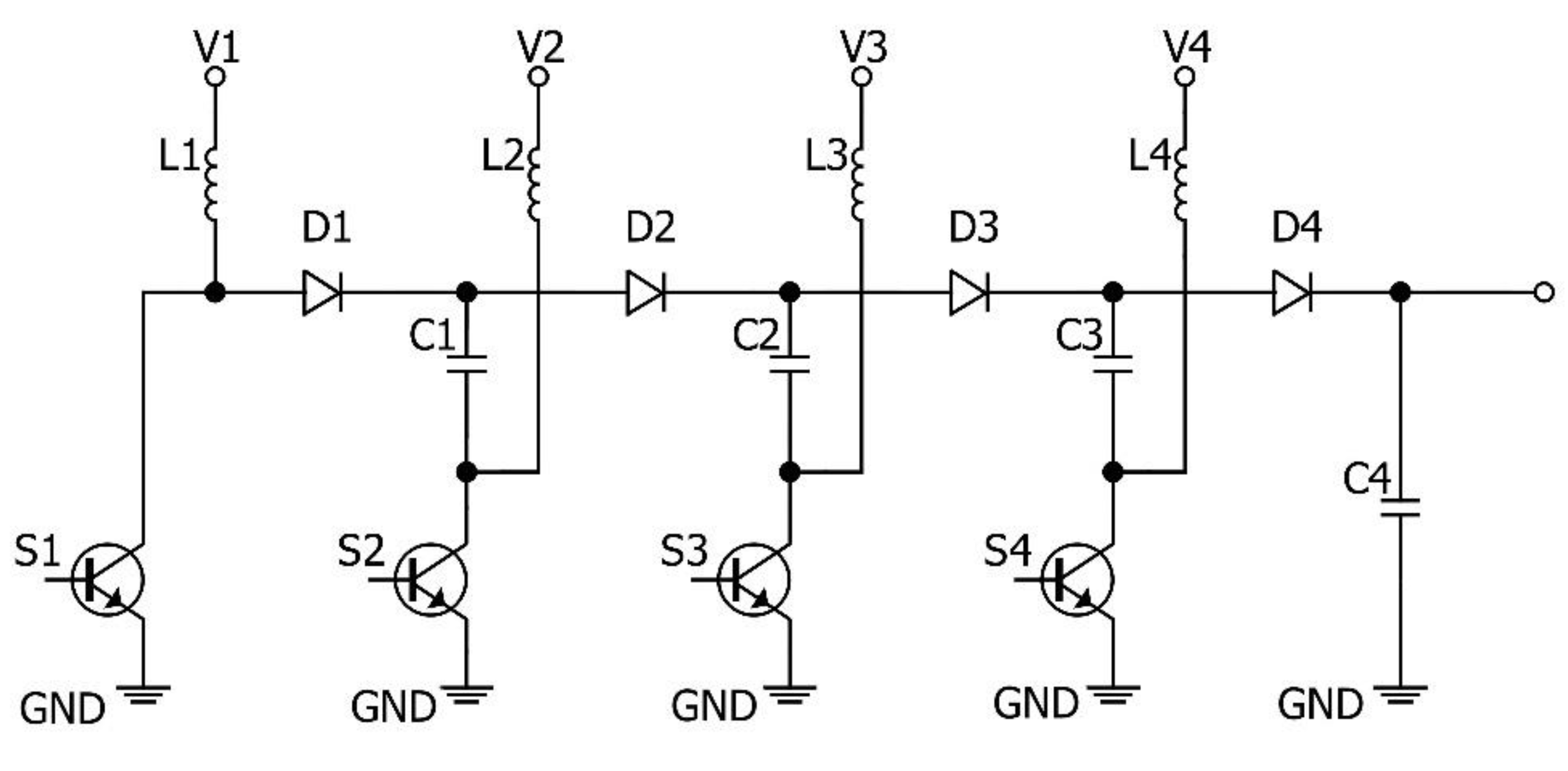
The authors in [67] proposed a simple, multi-input, non-isolated boost converter as a modified Dickson charge pump. Each energy harvester was connected to a diode-capacitor stage through a boost converter. The design (see Figure 5, based on [67]) has a simple control strategy based on a duty cycle, in which two inductors are discharging while the other two are charging. The proposed design is easy to control. It provides high voltage gain and reduces the switching. It is suitable for low-voltage energy harvesting applications and multi-source energy harvesting with different current–voltage characteristics. The disadvantage of this design is the use of inductors, which increases the size and the cost, especially when a large number of harvesters is involved [68].

3.4.4. Parallel Form

In [69,70], the authors described a topology to combine the energy from two energy sources connected in parallel through a Multiple Input Boost Converter (MIBC). The control strategy combining the energy from the resources (see Figure 6, based on [69]) consisted in time division between them. This strategy will lead to energy waste, because the resources cannot deliver the energy simultaneously.

3.5. Linear Regulator

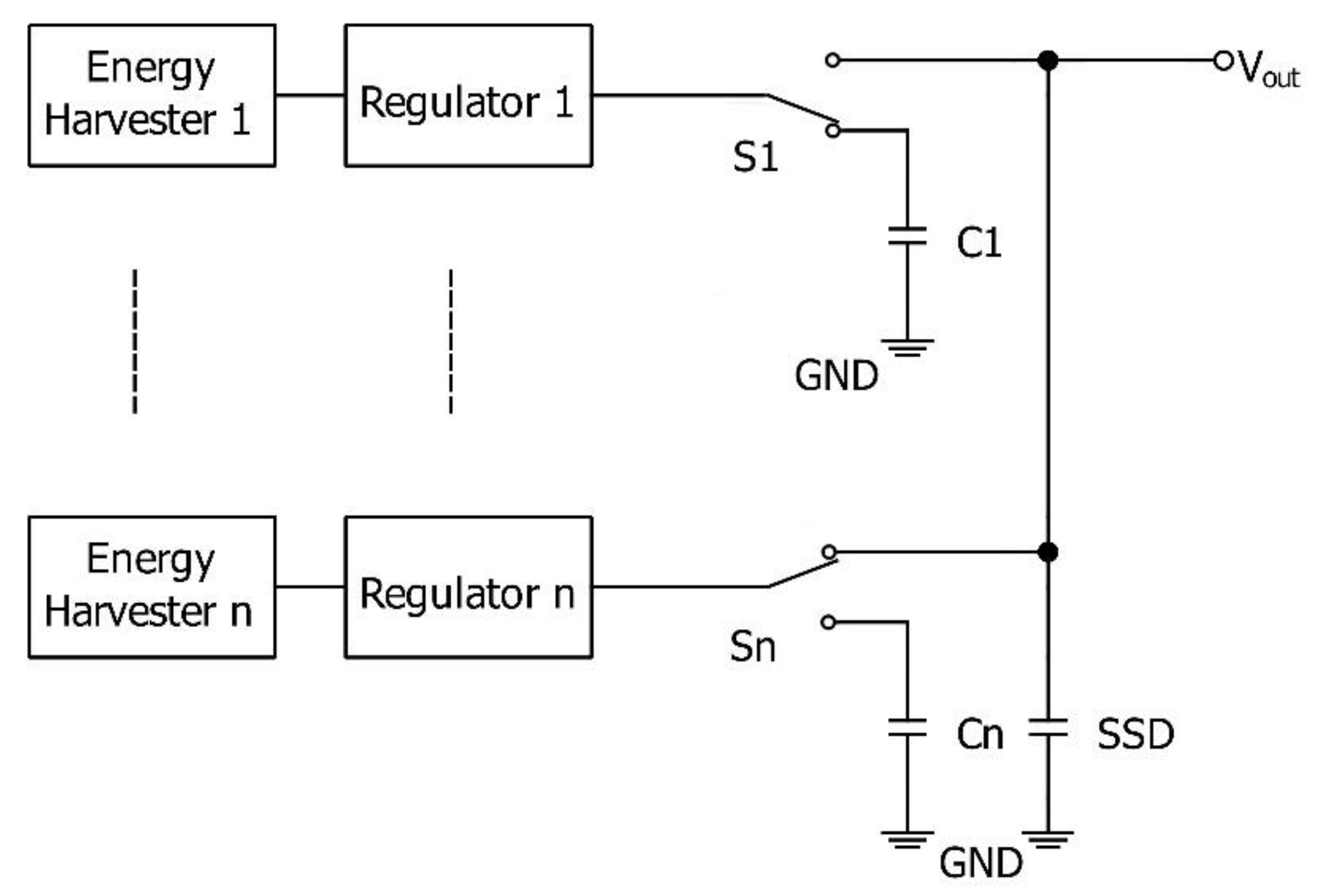
A low dropout (LDO) regulator performs regulation of the output voltage. LDO regulators do not generate switching noise. They are characterized by their small size and simple design (see Figure 7, based on [71]). Their main disadvantage is the production of waste heat. The LDO regulator energy-combining technique is based on providing the same voltage value for each energy harvester output to charge the storage device simultaneously. As an LDO is required for each input, the heat production (along with the costs) rises in proportion to the device complexity.
The authors presented a multi-harvesting power chip that worked in the voltage range of up to 2.5 V, and its total power consumption was 160 µW [71]. The system was batteryless and designed to collect energy from the indoor light environment, mechanical vibrations source, electromagnetic field, and thermal energy. However, they did not implement the thermal generator, due to restrictions in size. There was a subsystem for each energy source that contained the harvester and the conditioning circuit to optimize the energy from each source. A multiple energy storage device was used to guarantee the collection of the energy from each source simultaneously. The multi-harvesting power chip consisted of three main circuits: the rectifier to convert the AC signal from the vibration and electromagnetic source to a DC signal; the regulator core (consisting of a bandgap circuit that determines the reference voltage and a low dropout regulator); and the control unit.
The control unit permanently monitored the voltage and compares it to two trigger values, Vmax and Vmin, in order to control the power flow to the load using a PMOS switch. When the voltage in the single storage device (SSD) reached the Vmax, the control unit connected it to the load. When the voltage dropped to the Vmin, it was disconnected. The LDO regulator defined the Vmax value. The Vmin value was defined by the load as the minimum voltage required to run the load, and the reference voltage was defined by the bandgap circuit to reduce the power consumption. The system used a power on reset (POR); additionally, it was used as a startup mechanism with the BG circuit. When the voltage was increasing from zero to Vmax for the first time, only the BG circuit and POR were activated, but when the voltage reached the value of the Vmin, the POR circuit activated the remaining parts of the system.
The presented system combines the harvested energy from different resources simultaneously, so there is no waste of the energy available for harvesting. However, using the linear regulators for each source will increase the energy consumption. The system is not universal—it is limited to applications where the voltage value is lower than 2.5 V [71]. An example of such a system is given in [72].

3.6. Multiplexing Techniques

A multiplexing technique consists in combining the energy from different resources. There is a control algorithm that lets each harvester charge the storage device for a specified interval of time. This technique uses a controller, controllable switches, and a synchronization oscillator to perform the multiplexing. The efficiency of this technique depends on the algorithm used. Its disadvantage is the system complexity and the consumption of energy by the components used to perform the multiplexing.
In [73], the authors provided the design of a combiner that had an arbitrary number of inputs to combine energy from several energy harvesters. This combiner consisted of a controller and controllable switches. The algorithm was based on comparison of the harvester output with a specified voltage level (the threshold voltage). When the output voltage of one of the harvesters was higher than the threshold voltage, this harvester was connected to the load through a capacitor by activating the corresponding controllable switch for a specified interval of time Δt. When the voltage of the connected capacitor of the harvester dropped below the threshold, the controller checked whether the voltage of the previously connected harvester was higher than the threshold. If it was, it connected this harvester to the load for a specified interval of time Δt and disconnected the previously connected harvester. If the voltage of the connected capacitor of the harvester was still higher than the threshold, then the controller extended the connecting time interval Δt. In the case that none of the harvesters had a higher voltage than the threshold, the controller disconnected the load for the interval of time Δt and repeated the process. The idea behind this algorithm is to divide the time among the harvesters to collect the energy from all of them. CMOS technology (0.13 μm) was used for IC fabrication. The maximum efficiency of the energy combiner for three inputs was 95%, and its power consumption was 1.55 µW.
In [74], the authors proposed a system to combine energy from two harvesters with MPPT based on dividing the time between the resources (with respect to the highest efficiency of energy conversion) to energize an inductor. The system consisted of four PMOS and NMOS transistors to perform the switching, five capacitors, an inductor, and a controller. The controller defined three periods of time: ON time (TON), which was the interval of energizing of the inductor; OFF time (TOFF) when the energy was delivered to the load; and idle time (TIDLE), during which the inductor was set to float to reduce the energy leakage. In addition, it defined three working modes: single source mode (SSM), dual source mode (DSM), and backup mode (BM). Each mode had its own switch configuration. The system monitored the ambient environment condition to select the working mode. The SSM was applied when one of the resources was available, the DSM was applied when two resources were available, and the BM was applied when no resource was available. The proposed system had a peak efficiency of 84.4%.

3.7. Switched Capacitors

A switched capacitor [75] is an electronic circuit consisting of switches and capacitors (see Figure 8, based on [76,77]). Its simplistic topology is composed of two switches (S1 and S2) and one capacitor. It has two phases, which are the charging phase, when S1 is closed and S2 is open (the energy is being stored in the capacitor), and the discharging phase (S1 is opened and S2 is closed so that the energy can be released from the capacitor). Using a switched capacitor to combine the energy is based on converting the current of one harvester to its AC form, combining the energy through the capacitors, and then rectifying the current using transistors [76].
For example, in [63], the authors proposed a design to combine the energy using the switched capacitor technique. The setup consisted of five main subsystems: passive start-up (PSU), ranking and level detection, MPPT control, combiner core, and control logic. An external under voltage lockout (UVLO) circuit was connected to the system to enable its operation. The energy storage system consisted of two capacitors: a high-capacity main capacitor that stored the harvested energy to feed the load, and a secondary capacitor that sped up the start-up process.
The PSU selected the harvester with the highest generated energy to charge the secondary capacitor. When it was fully charged, the UVLO generated the power good (PG) signal to activate the system. Then, the system repeated the evaluation of the inputs during a short waiting cycle. When the open circuit conditions (OCC) were met and the control logic selected two of the four inputs to connect them to the combiner core, where a differential low-power oscillator was used to convert the current I2 of the second harvester to its AC form, the pulse-shaped form was coupled by charging the capacitors C1 and C2. The output of the switched capacitor charged one capacitor. The VC voltage would equal the sum of V1 and V2. The system was fabricated using the 0.13 μm CMOS technology. It had a peak tracking efficiency of 96%, a maximum power conversion of 87.2% at 198 μW of output power and 72% at 981 μW. The switched capacitor was capable of concurrent energy combining, so there was no need for time division multiplexing. In addition, it was an integrated solution, which implied its small size and easy packing.

3.8. Shared Inductor

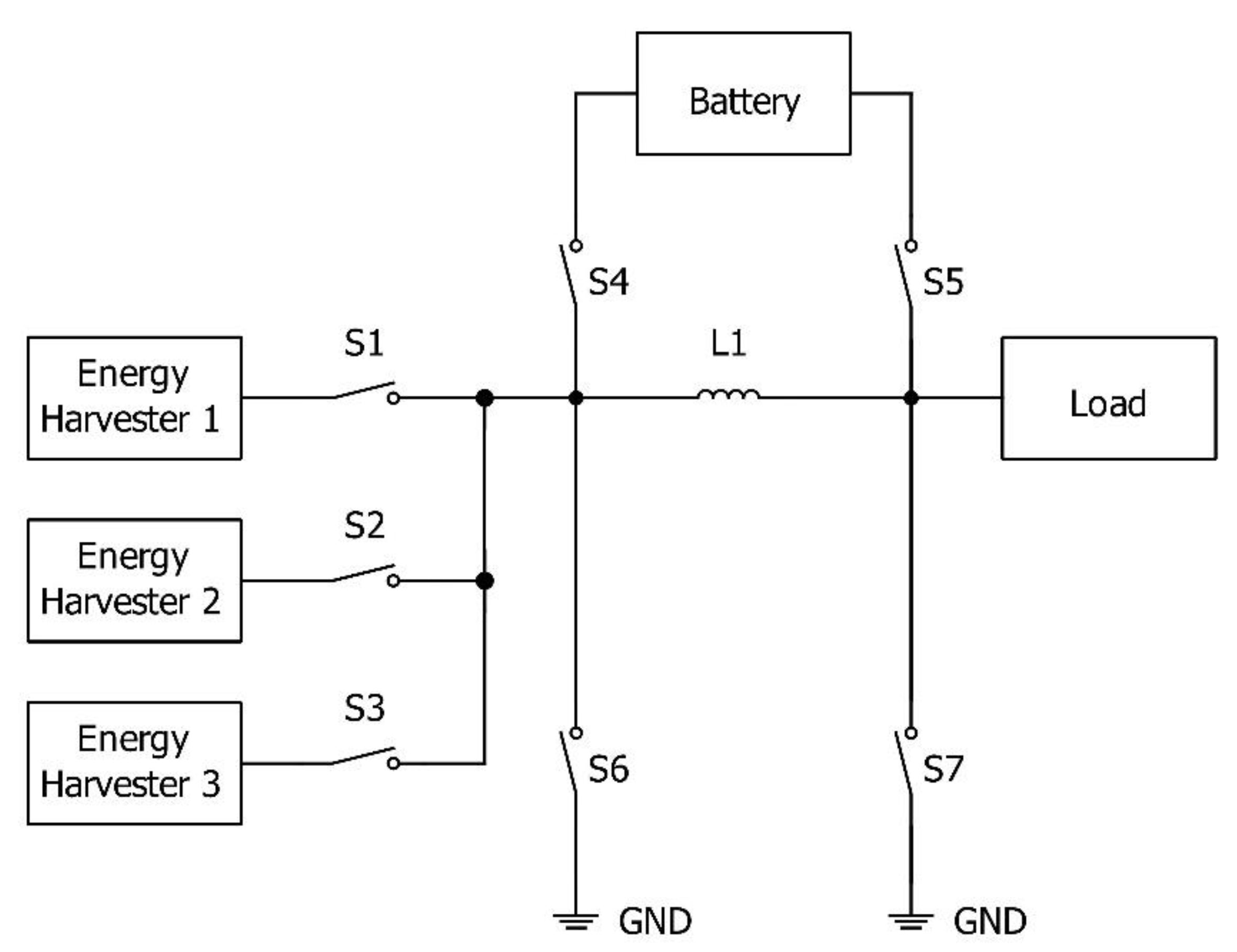
The shared inductor method to combine energy uses a shared inductor on a buck-boost converter to store the energy from different resources (see Figure 9, based on [77,78]). The buck-boost converter can work in discontinuous conduction mode (DCM), with the possibility of implementing the MPPT by controlling the frequency of the buck-boost converter switches. This method is efficient in low-power applications. Its disadvantage is the size of the inductor, which increases the size of the circuit, and, thus, the total dimensions and costs.
In [78], the authors proposed a design to combine energy from three harvesters—a thermoelectric generator (TEG), a biofuel cell (BFC), and a photovoltaic (PV) panel—using a single-stage shared inductor. The proposed design contained controllable switches, a shared maximum power point tracking controller, a shared output regulator, a shared inductor, a battery, and a controller. The control method gave each harvester a branch one charging interval (T1) to charge the shared inductor and a switching frequency depending on the harvester output comparator (based on the MPPT and the available ambient energy). When the T1 period was over, and the zero current detector (ZCD) circuit detected a zero inductor current, the controller checked the state of the other harvesters. If both of them had high output, the controller selected the first (predefined) harvester in the sequence and gave its branch a charging interval T2 to charge the inductor. If both of the remaining harvesters had low output, then the controller repeated the sequence from the beginning. The peak efficiency amounted to 89%. The reaching of an even higher (92%) peak efficiency is discussed in [79].
The design proposed in [80] combined energy from three resources: vibration, PV, and RF. It contained controllable switches, comparators, a maximum power point circuit, oscillators, a shared inductor, and capacitors. The goal was to achieve DCM in three phases: energize; dump and then wait by charging the shared inductor in the first phase, followed by dumping the stored energy from the inductor into a capacitor to maintain a constant peak inductor current in the second phase; and the waiting phase to charge the capacitor of each transducer. The efficiency was 87% for the input power of 20 μW. Other examples of shared inductor applications and analysis are presented in [81] and [82].

4. Comparison and Discussion

4.1. Description of the Criteria

In Section 3, we presented eight of the most popular methods used as control strategies for hybrid energy harvesting (while one of them—the MIBC—is divided into four sub-strategies). In order to be able to compare them, we have developed a set of criteria describing their key characteristics (see Table A1 in Appendix A).
Complexity describes how complicated the scheme is. The possible values are High, Medium, and Low, where High implies some difficulties with the device introduced by its size, price, reliability etc.
Simultaneity states whether it is possible to harvest energy from two or more resources at the same time (binary criterion—Yes/No).
Typical number of inputs indicates the total number of resources that can be connected to the system.
Typical efficiency of an energy harvester is based on specific results referenced in Table A1 (Appendix A). Unfortunately, this value is not available for all considered strategies.
Technology quotes (where available) the manufacturing standard that influences total dimensions, own energy consumption, price etc. This parameter is also based on specific results referenced in Table A1 (Appendix A).
Cost compares the expected system price to other solutions at the present time. Of course, this parameter strongly depends on the customers’ demands, quantity, speed of delivery, etc.; therefore, we provide only rough estimations of the price range.
Reliability/sustainability assesses the ability of the device to deliver energy without interruptions and for a satisfactorily long period of time (with respect to the envisaged application).
Environment dependence expresses how much the system is (or is not) dependent on the changing ambient conditions (such as insolation, wind, presence of vibrations etc.). In this case, of course, high dependence is undesired.
MPPT indicates whether Maximum Power Point Tracking is (or can be) used.
Scalability indicates whether the given strategy allows for the combination of a particular device into higher-order structures so that the output power can be increased.
Size and mass represent the expected typical physical dimension of the technology. This criterion is expressed by the values Small, Medium, and Large. It depends on the number and size of involved elements and on the base technology (see the column “Technology”).
Energy consumption provides information on typical own (internal) energy demands of the device. It increases with the number of involved elements and depends on their nature/characteristics.
Applicability expresses the extent to which the technology can be deployed in different scenarios. This extent is estimated with respect to suitable applications and environments.

4.2. Discussion of the Strategies

Supplementary use of energy sources: Low complexity is achieved thanks to the fact that, within the fixed design, there is no control unit needed for just two harvesters that work simultaneously. This is also reflected in the small dimensions, low cost, and high efficiency. The limited reliability is due to the fact that the output depends on just two different resources that, theoretically, can become unavailable (or insufficient) at the same time; however, this strategy is designed for specific environments where the resources should be satisfactory by definition.
Power ORing: Likewise, the complexity here is low for the same reason (no control unit is present in the design, and the winner is the resource with the highest output voltage); therefore, the cost is low as well. Any number of harvesters can be connected in the setup, which is its major advantage, because the higher their number, the higher the reliability. In addition, the connected harvesters can be of different types, thus providing independence from any specific environment.
Voltage level detection: In this case, the high complexity is due to the need for a control unit, suitable control algorithms, a voltage detection method, and additional devices, such as switches and timers. Thus, the cost is higher than in the previous cases. The total efficiency largely depends on a particular design. The number of inputs can be increased as necessary to improve the reliability or independence of the environment. Nevertheless, at the same time, the growing number of harvesters in the setup increases the cost and the own consumption (thus decreasing the efficiency).
Multiple input boost converters: Here, the complexity varies for different types with respect to their specific topologies, i.e., whether a controller is present or not. Most of the properties, however, are very similar. The medium- to high-complexity design (specifically with the presence of inductors) implies relatively large dimensions, as well as high costs. The typical number of inputs is in fact limited by the same factor, as the number of inductors increases accordingly. As with the previous strategy, increasing the number of harvesters in the setup is possible in principle, but it increases the cost and the consumption (thus decreasing the efficiency). As the typical number of harvesters in the setup is only two, this implies high dependency on the specific environment, and, thus, low reliability/sustainability. All versions of the MIBC support MPPT implementation. Finally, all versions except the parallel one support simultaneous utilization of the inputs; in the parallel version, where the inputs are connected side-by-side as with the Power ORing, the input with the higher voltage is selected by definition, and, therefore, they cannot all be active at the same time. However, unlike the voltage level detection method, there is not any sophisticated algorithm involved in identifying the higher voltage. The medium applicability is due to the large size of the converters.
Linear regulator: Its complexity can be characterized as medium, since it can use a linear regulator instead of a controller, which translates to medium costs. All harvesters share the same output, and thus work simultaneously by definition. The typical number of inputs is three, but in principle, there is no restriction, which implies limited reliability with respect to the given environment (yet the different inputs still guarantee a certain level of independence). Increasing the number of inputs can be used as a way to increase the output power (scalability). Its low applicability is due to the fact that it requires a relatively high amount of energy to operate itself.
Multiplexing techniques: Their high complexity is linked to the use of a controller and some kind of timing device (oscillator), as well as controllable switches. For the same reason, their implementation is relatively expensive. We consider the environment dependence as medium, because the number of inputs can be increased, but such a step implies increased complexity at the same time. By principle (i.e., time sharing), the inputs cannot be utilized simultaneously. The reliability/sustainability is limited, due to the environment dependence described above. Scalability to increase the output power is supported, but it leads to increased design complexity and requires modification of the control algorithm.
Multiplexing techniques are based on time sharing. They can be used in many different strategies, e.g., in Shared inductors or in Voltage level detection.
Switched capacitors: Here as well, the high complexity and cost are implied by the need to use a controller. The simultaneity principle was explained hereinbefore. MPPT control can be implemented. With respect to the typical number of inputs (which is two to four), we can characterize the environment dependence as medium and the reliability/sustainability as relatively high. Again, the scalability is supported at the price of increased complexity.
Shared inductors: In order to charge the shared inductor, identical voltage from all harvesters is required; therefore, the time multiplexing principle is used, which (by principle) does not allow for simultaneous utilization of the inputs. This form of control requires a controller, which increases the dimensions and price, together with the use of inductors. As for the reliability/sustainability, environment dependence, and scalability, the comments are identical as in the previous paragraph.
In general, it should be pointed out that the proposed criteria and their evaluation are based on typical representations documented in the quoted resources and on the assessment by the authors; however, specific applications for specific environments may require different approaches.

5. Conclusions

As a preparatory work, we performed an extensive survey that mainly reviewed the three most important publication databases. The number of EH-oriented publications has been growing significantly over the past 10 years, which clearly demonstrates the trend to seek alternative energy sources (Section 1.2).
Taking into consideration the generally known shortcomings of EH, we focused on HEH techniques (Section 1.2). Many authors use different control strategies for the management of HEH; however, some of them do not publish complete details of their approaches. It is also significant that there is no publication available in the field that would reasonably summarize and describe the management strategies of HEH systems.
Within the survey, we identified eight dominant strategies for managing HEH systems (Section 3): Supplementary use of various energy sources, Power ORing, Voltage level detection, Multiple-input boost converter (offering several implementation alternatives), Linear regulator, Multiplexing techniques, Switched capacitors, and Shared inductor.
We analyzed all these strategies in detail. Section 3, with its eight subsections, deals with the individual control strategies. In the beginning of each subsection, we described the key features for each strategy. For each of the strategies, we have analyzed and compared the principle schemes and proposed a simplified one that clearly yet sufficiently describes the function. Additionally, we provided examples of best practices for each strategy. In addition to such a comprehensive description of these dominant strategies, their comparison can be very useful for all interested readers. Subsequently, we defined 10 criteria and their possible values, which we described in Section 4.1. In Appendix A, we used these criteria to evaluate the individual HEH strategies with respect to the state of the art. Our textual comments in Section 4.2 are aligned with the values contained in the table, including the justification of the evaluation of some criteria that may seem subjective from certain points of view.
The rating of the criteria is highly dependent on the actual purpose, target application, specific environment, etc. Therefore, we avoid any classification of the priorities, while realizing that the weighting of the individual criteria should be proposed by the designer of a particular system that uses HEH as its arbitrary or main source of energy.
Here, it is necessary to emphasize that, as we mentioned in the introduction, it is not possible to find all the necessary data. Unfortunately, the efficiency and the technology are often not presented in all sources; therefore, only data that could be verified independently was included in the comparison. The comparison is based on typical values.An attentive reader will certainly find exceptions to the listed values, but such cases shall generally be rare in this area.
As for the future development of HEH techniques, we can envisage specialization for the most typical areas of application. The most important challenges consist in increasing the efficiency, decreasing the cost, and improving the sustainability, for example by eliminating the energy storage subsystem. This approach would reduce the size and cost of the device, making it more environment-friendly, but it requires relying only on those sources of energy that are available when necessary.
Harvesting the energy from different merged resources will increase the own energy consumption of the harvesting system. The question is whether the extra harvested energy (obtained thanks to the merging of resources) is sufficient to compensate this increased consumption. The limits of profitability shall be found in this respect.
In general, all the presented strategies have a chance to be developed in the future. Embedded systems with advanced processing techniques and low power consumption seem to be promising, especially the Switched capacitor and Shared inductor (and perhaps Multiplexing techniques as well). Our opinion is based on the experience concluding that such systems should be software-controlled (while the “natural” control based on simple physical quantities will not be satisfactory in the future). This implies the necessity to include a controller in the system design, which ultimately leads to the use of embedded systems.
An important issue is the application of HEH in environments where one of the sources is missing or suppressed. Non-embedded systems, such as the Power ORing or Voltage level detection, that are controlled directly by a specific physical quantity (e.g., voltage, illumination etc.) are less sophisticated, with limited possibilities of software control and management. Obviously, there are restrictions regarding their applications. If the Power ORing is used in an environment where one of the sources is suppressed, the stronger one will feed the circuit. Therefore, at that specific moment, two energy resources will not be used at all. Thus, we would increase the size, cost, etc., using only one EH. As the design of non-embedded systems is fixed, it cannot be modified easily. This confirms the embedded systems to be more promising for the future, thanks to their higher flexibility.
As with other battery-powered devices, the environmental issues are carefully and critically observed. The most limiting factor is the battery lifetime itself. Uncontrolled battery charging and discharging leads to its substantially reduced lifetime, which implies the need for frequent replacement and a higher load on the environment. From this point of view, embedded systems are much more sustainable. In general, the major challenge consists in the future of embedded systems design. The development should lead towards size reduction, higher applicability, software-based control, etc. We assume the application of deep learning techniques and artificial intelligence in system control, and, above all, the environment changes prediction (note that a huge volume of data is needed for reasonable predicting, which is, however, not available at this moment).

Author Contributions

Conceptualization, D.M. and J.H. (Jaromir Hrad); methodology, D.M. and J.H. (Jaromir Hrad); formal analysis, A.O. and D.M.; investigation, A.O.; resources, A.O. and J.H. (Jiri Hajek); writing—original draft preparation, J.H. (Jaromir Hrad), A.O., D.M. and J.H. (Jiri Hajek); supervision, D.M. and J.H. (Jaromir Hrad). All authors have read and agreed to the published version of the manuscript.

Funding

This research received no external funding.

Institutional Review Board Statement

Not applicable.

Informed Consent Statement

Not applicable.

Data Availability Statement

Not applicable.

Acknowledgments

The research has been supported by the institutional grant system of the Faculty of Electrical Engineering, the Czech Technical University in Prague.

Conflicts of Interest

The authors declare no conflict of interest. The funders had no role in the design of the study; in the collection, analyses, or interpretation of data; in the writing of the manuscript; or in the decision to publish the results.

Appendix A. HEH Control Strategies Comparison Table

Table A1. Comparison of HEH Control Strategies.
Criteria
MethodComplexitySimultaneityTypical Number of InputsTypical EfficiencyTechnologyCostReliability/Sustaina-BilityEnviron-ment DependenceMPPTScalability
Supplementary use of energy sourcesLowYes290.5%CMOS 13 nmCheapLimitedHighNoNo
Power ORingLowNoUnlimited80–94% CheapHighLowYesYes
Voltage level detectionHighNo2–3/unli-mited72–94.67%65 nmUpper mediumHighMediumYesYes
Multiple input boost converter—serialMediumYes2 ExpensivePoorHighYesYes
Multiple input boost converter—magneticHighYes284% ExpensivePoorHighYesYes
Multiple input boost converter—specialHighYes2 ExpensivePoorHighYesYes
Multiple input boost converter—parallelMediumNo285% ExpensivePoorHighYesYes
Linear regulatorMediumYes3 MediumLimitedMediumYesYes
Multiplexing techniquesHighNo3 pMOS/nMOSExpensiveLimitedMediumYesYes
Switched capacitorsHighYes272–87.2%CMOS 130 nmExpensiveHighMediumYesYes
Shared inductorHighNo387–89%FDSOI 28 nmExpensiveHighMediumYesYes
Criteria
MethodSize and MassEnergy ConsumptionApplicabilityReferences
Supplementary use of energy sourcesSmallLowLow[50,51,52]
Power ORingSmallLow-mediumHigh[53,54,55,56,57,58,59]
Voltage level detectionMediumLow-mediumHigh[60,61,62,63,64]
Multiple input boost converter—serialLargeMediumMedium[65]
Multiple input boost converter—magneticLargeMediumMedium[66]
Multiple input boost converter—specialLargeMediumMedium[67,68]
Multiple input boost converter—parallelLargeMediumMedium[69,70]
Linear regulatorMediumMediumLow[71,72]
Multiplexing techniquesMediumMedium-highHigh[73,74]
Switched capacitorsMediumHighHigh[63,75,76]
Shared inductorLargeHighHigh[77,78,79,81,82]

References

  1. Silicon cells harvest Sun’s energy. Electr. Eng. 1958, 77, 1073–1074. [CrossRef]
  2. Quick, G.R. Acceleration Analysis of Crop Cutting by High-Speed Photography. SMPTE J. 1976, 85, 403–408. [Google Scholar] [CrossRef]
  3. Ramsay, M.J.; Clark, W.W. Piezoelectric energy harvesting for bio MEMS applications. In Proceedings of the Spie’s 8th Annual International Symposium on Smart Structures and Materials, Newport Beach, CA, USA, 5–8 March 2001; pp. 429–438. [Google Scholar] [CrossRef]
  4. Mickle, M.H.; Lovell, M.; Mats, L.; Neureuter, L.; Gorodetsky, D. Energy harvesting, profiles, and potential sources. Int. J. Parallel. Distrib. Syst. Netw. 2001, 4, 150–160. [Google Scholar]
  5. Yu, H.; Li, Y.; Shang, Y.; Su, B. Design and investigation of photovoltaic and thermoelectric hybrid power source for wireless sensor networks. In Proceedings of the 3rd IEEE International Conference on Nano/Micro Engineered and Molecular Systems, Sanya, China, 6–9 January 2008; pp. 196–201. [Google Scholar] [CrossRef]
  6. Qidwai, M.A.; Thomas, J.P.; Kellogg, J.C.; Baucom, J. Energy harvesting concepts for small electric unmanned systems. In Proceedings of the Smart Structures and Materials, San Diego, CA, USA, 14–18 March 2004; pp. 84–85. [Google Scholar] [CrossRef]
  7. Bai, Y.; Jantunen, H.; Juuti, J. Energy harvesting research: The road from single source to multisource. Adv. Mater. 2018, 30, e1707271. [Google Scholar] [CrossRef] [PubMed] [Green Version]
  8. Khan, A.; Hoq, T.; Karim, A.H.M.Z.; Alam, K.; Howlader, M.; Rajkumar, R.K. Energy harvesting—Technical analysis of evolution, control strategies, and future aspects. J. Electron. Sci. Technol. 2019, 17, 116–125. [Google Scholar] [CrossRef]
  9. Alsaba, Y.; Rahim, S.K.A.; Leow, C.Y. Beamforming in Wireless Energy Harvesting Communications Systems: A Survey. IEEE Commun. Surv. Tut. 2018, 20, 1329–1360. [Google Scholar] [CrossRef]
  10. He, Y.; Cheng, X.; Peng, W.; Stüber, G.L. A survey of energy harvesting communications: Models and offline optimal policies. IEEE Commun. Mag. 2015, 53, 79–85. [Google Scholar] [CrossRef]
  11. Hu, S.; Chen, X.; Ni, W.; Wang, X.; Hossain, E. Modeling and Analysis of Energy Harvesting and Smart Grid-Powered Wireless Communication Networks: A Contemporary Survey. IEEE Trans. Green. Commun. Netw. 2020, 4, 461–496. [Google Scholar] [CrossRef]
  12. Kosunalp, S. MAC protocols for energy harvesting wireless sensor networks: Survey. ETRI J. 2015, 37, 804–812. [Google Scholar] [CrossRef]
  13. Lu, X.; Wang, P.; Niyato, D.; Kim, D.I.; Han, Z. Wireless networks with rf energy harvesting: A contemporary survey. IEEE Commun. Surv. Tut. 2015, 17, 757–789. [Google Scholar] [CrossRef] [Green Version]
  14. Rezaei, F.; Hempel, M.; Sharif, H. A survey of recent trends in wireless communication standards, routing protocols, and energy harvesting techniques in E-health applications. In Wearable Technologies: Concepts, Methodologies, Tools, and Applications; IGI Global: Hershey, PA, USA, 2018; pp. 1479–1502. ISBN 978-152-255-485-1. [Google Scholar] [CrossRef]
  15. Sarkar, N.I.; Singh, D.P.; Ahmed, M. A survey on energy harvesting wireless networks: Channel capacity, scheduling, and transmission power optimization. Electronics 2021, 10, 2342. [Google Scholar] [CrossRef]
  16. Xu, X.; Shu, L.; Guizani, M.; Liu, M.; Lu, J. A Survey on Energy Harvesting and Integrated Data Sharing in Wireless Body Area Networks. Int. J. Distrib. Sens. Netw. 2015, 11, 438695. [Google Scholar] [CrossRef]
  17. Zhao, N.; Zhang, S.; Yu, F.R.; Chen, Y.; Nallanathan, A.; Leung, V.C.M. Exploiting Interference for Energy Harvesting: A Survey, Research Issues, and Challenges. IEEE Access 2017, 5, 10403–10421. [Google Scholar] [CrossRef]
  18. Tedeschi, P.; Sciancalepore, S.; Di Pietro, R. Security in Energy Harvesting Networks: A Survey of Current Solutions and Research Challenges. IEEE Commun. Surv. Tut. 2020, 22, 2658–2693. [Google Scholar] [CrossRef]
  19. Singla, P.; Sarangi, S.R. A survey and experimental analysis of checkpointing techniques for energy harvesting devices. J. Sys. Archit. 2022, 126, 102464. [Google Scholar] [CrossRef]
  20. Ahmed, I.; Butt, M.M.; Psomas, C.; Mohamed, A.; Krikidis, I.; Guizani, M. Survey on energy harvesting wireless communications: Challenges and opportunities for radio resource allocation. Comp. Netw. 2015, 88, 234–248. [Google Scholar] [CrossRef]
  21. Paz, H.P.; Silva, V.S.; Cambero, E.V.V.; Araújo, H.X.; Casella, I.R.S.; Capovilla, C.E. A survey on low power RF rectifiers efficiency for low cost energy harvesting applications. AEU Int. J. Electron. Commun. 2019, 112, 152963. [Google Scholar] [CrossRef]
  22. Sherazi, H.H.R.; Zorbas, D.; O’Flynn, B. A Comprehensive Survey on RF Energy Harvesting: Applications and Performance Determinants. Sensors 2022, 22, 2990. [Google Scholar] [CrossRef]
  23. Soyata, T.; Copeland, L.; Heinzelman, W. RF Energy Harvesting for Embedded Systems: A Survey of Tradeoffs and Methodology. IEEE Circ. Syst. Mag. 2016, 16, 22–57. [Google Scholar] [CrossRef]
  24. Sharma, H.; Haque, A.; Jaffery, Z.A. Solar energy harvesting wireless sensor network nodes: A survey. J. Renew. Sustain. Ener. 2018, 10, 023704. [Google Scholar] [CrossRef]
  25. Dziadak, B.; Makowski, Ł.; Michalski, A. Survey of energy harvesting systems for wireless sensor networks in environmental monitoring. Metrol. Meas. Syst. 2016, 23, 495–512. [Google Scholar] [CrossRef]
  26. Nguyen, P.D.; Kim, L.W. Sensor System: A Survey of Sensor Type, Ad Hoc Network Topology and Energy Harvesting Techniques. Electronics 2021, 10, 219. [Google Scholar] [CrossRef]
  27. Sah, D.K.; Amgoth, T. Renewable energy harvesting schemes in wireless sensor networks: A Survey. Inform. Fusion 2020, 63, 223–247. [Google Scholar] [CrossRef]
  28. Singh, J.; Kaur, R.; Singh, D. Energy harvesting in wireless sensor networks: A taxonomic survey. Int. J. Energ. Res. 2021, 45, 118–140. [Google Scholar] [CrossRef]
  29. Williams, A.J.; Torquato, M.F.; Cameron, I.M.; Fahmy, A.A.; Sienz, J. Survey of Energy Harvesting Technologies for Wireless Sensor Networks. IEEE Access 2021, 9, 77493–77510. [Google Scholar] [CrossRef]
  30. Othman, A.; Maga, D. Relation between security and energy consumption in wireless sensor network (WSN). In Proceedings of the 2018 New Trends in Signal Processing (NTSP), Demanovska Dolina, Slovakia, 10–12 October 2018. [Google Scholar]
  31. Othman, A.; Maga, D. Indoor Photovoltaic Energy Harvester with Rechargeable Battery for Wireless Sensor Node. In Proceedings of the 18th International Conference on Mechatronics (Mechatronika 2018), Brno, Czech Republic, 5–7 December 2018; pp. 397–402. [Google Scholar]
  32. Dudak, J.; Skovajsa, M.; Sladek, I. Proposal of a Communication Protocol for Smart Sensory Systems. In Proceedings of the 2014 16th International Conference on Mechatronics (Mechatronika 2014), Brno, Czech Republic, 3–5 December 2014; pp. 107–112. [Google Scholar]
  33. Gaspar, G.; Dudak, J.; Beluhova, M.; Stremy, M.; Budjac, R.; Sedivy, S.; Tomas, B. IoT-Ready Temperature Probe for Smart Monitoring of Forest Roads. Appl. Sci. 2022, 12, 743. [Google Scholar] [CrossRef]
  34. Dudak, J.; Gaspar, G.; Sedivy, S.; Pepucha, L.; Florkova, Z. Road structural elements temperature trends diagnostics using sensory system of own design. In Proceedings of the International Conference on Building up Efficient and Sustainable Transport Infrastructure (BESTInfra), Prague, Czech Republic, 21–22 September 2017. [Google Scholar] [CrossRef]
  35. Lazaro, A.; Villarino, R.; Girbau, D. A Survey of NFC Sensors Based on Energy Harvesting for IoT Applications. Sensors 2018, 18, 3746. [Google Scholar] [CrossRef] [Green Version]
  36. Ma, D.; Lan, G.; Hassan, M.; Hu, W.; Das, S.K. Sensing, Computing, and Communications for Energy Harvesting IoTs: A Survey. IEEE Commun. Surv. Tut. 2020, 22, 1222–1250. [Google Scholar] [CrossRef]
  37. Sandhu, M.M.; Khalifa, S.; Jurdak, R.; Portmann, M. Task Scheduling for Energy-Harvesting-Based IoT: A Survey and Critical Analysis. IEEE Internet Things 2021, 8, 13825–13848. [Google Scholar] [CrossRef]
  38. Sun, H.; Yin, M.; Wei, W.; Li, J.; Wang, H.; Jin, X. MEMS based energy harvesting for the Internet of Things: A survey. Microsyst. Technol. 2018, 24, 2853–2869. [Google Scholar] [CrossRef]
  39. Khan, A.S.; Khan, F.U. A survey of wearable energy harvesting systems. Int. J. Energ. Res. 2022, 46, 2277–2329. [Google Scholar] [CrossRef]
  40. Sangha, H.S.; Sohal, H. Power challenges in wireless body area network for mobile health powered by human energy harvesting: A survey. Indian J. Sci. Technol. 2016, 9, 46. [Google Scholar] [CrossRef]
  41. Atallah, R.; Khabbaz, M.; Assi, C. Energy harvesting in vehicular networks: A contemporary survey. IEEE Wirel. Commun. 2016, 23, 70–77. [Google Scholar] [CrossRef]
  42. Zelenika, S.; Hadas, Z.; Bader, S.; Becker, T.; Gljuscic, P.; Hlinka, J.; Janak, L.; Kamenar, E.; Ksica, F.; Kyratsi, T.; et al. Energy Harvesting Technologies for Structural Health Monitoring of Airplane Components—A Review. Sensors 2020, 20, 6685. [Google Scholar] [CrossRef]
  43. Dwik, S.; Prabhaker, M.L.C. Survey on Energy Harvesting CMOS Sensor Based Digital Camera. Opt. Mem. Neural Netw. (Inf. Opt.) 2022, 31, 97–106. [Google Scholar] [CrossRef]
  44. Sudevalayam, S.; Kulkarni, P. Energy harvesting sensor nodes: Survey and implications. IEEE Commun. Surv. Tut. 2011, 13, 443–461. [Google Scholar] [CrossRef]
  45. Wang, Y.; Inman, D.J. A survey of control strategies for simultaneous vibration suppression and energy harvesting via piezoceramics. J. Intel. Matl. Syst. Str. 2012, 23, 2021–2037. [Google Scholar] [CrossRef]
  46. Weddell, A.S.; Magno, M.; Merrett, G.V.; Brunelli, D.; Al-Hashimi, B.M.; Benini, L. A survey of multi-source energy harvesting systems. In Proceedings of the Design, Automation and Test in Europe—DATE, Grenoble, France, 18–22 March 2013; pp. 905–908. [Google Scholar]
  47. European Commission. A European Green Deal. Available online: https://ec.europa.eu/info/strategy/priorities-2019-2024/european-green-deal_en (accessed on 6 June 2022).
  48. Goal 7—Department of Economic and Social Affairs. Ensure Access to Affordable, Reliable, Sustainable and Modern Energy for All. Available online: https://sdgs.un.org/goals/goal7 (accessed on 6 June 2022).
  49. Global Electricity Demand Is Growing Faster than Renewables, Driving Strong Increase in Generation from Fossil Fuels—News—IEA. Available online: https://www.iea.org/news/global-electricity-demand-is-growing-faster-than-renewables-driving-strong-increase-in-generation-from-fossil-fuels (accessed on 6 June 2022).
  50. Elhebeary, M.R.; Ibrahim, M.A.; Aboudina, M.M.; Mohieldin, A.N. Dual-source self-start high-efficiency microscale smart energy harvesting system for IoT. IEEE Trans. Ind. Electron. 2017, 65, 342–351. [Google Scholar] [CrossRef]
  51. Vankecke, C.; Assouère, L.; Wang, A.; Durand-Estèbe, P.; Caignet, F.; Dilhac, J.M.; Bafleur, M. Multisource and battery-free energy harvesting architecture for aeronautics applications. IEEE Trans. Power Electr. 2014, 30, 3215–3227. [Google Scholar] [CrossRef]
  52. Ishiyama, T. November. Output Characteristics of Energy Harvesting Using Multiple Energy Sources. In Proceedings of the 8th International Conference on Renewable Energy Research and Applications (ICRERA), Brasov, Romania, 3–6 November 2019; pp. 224–228. [Google Scholar]
  53. Othman, A.; Maga, D.; Hrad, J. Multi-input Energy Harvesting System with Battery Management Support for WSN Applications. In Proceedings of the 2022 20th International Conference on Mechatronics—Mechatronika (ME), Pilsen, Czech Republic, 7–9 December 2022; pp. 163–166. [Google Scholar]
  54. Fundamentals of Power System ORing—EETimes. Fundamentals of Power System ORing. Available online: www.eetimes.com/fundamentals-of-power-system-oring (accessed on 1 July 2022).
  55. Deng, F.; Yue, X.; Fan, X.; Guan, S.; Xu, Y.; Chen, J. Multisource energy harvesting system for a wireless sensor network node in the field environment. IEEE Internet Things 2018, 6, 918–927. [Google Scholar] [CrossRef]
  56. Ferrari, M.; Ferrari, V.; Guizzetti, M.; Marioli, D.; Taroni, A. Piezoelectric multifrequency energy converter for power harvesting in autonomous microsystems. Sensor Actuat. A Phys. 2008, 142, 329–335. [Google Scholar] [CrossRef]
  57. Carli, D.; Brunelli, D.; Benini, L.; Ruggeri, M. An effective multi-source energy harvester for low power applications. In Proceedings of the Design, Automation and Test in Europe—DATE, Grenoble, France, 14–18 March 2011; pp. 1–6. [Google Scholar] [CrossRef]
  58. Tan, Y.K.; Panda, S.K. Energy harvesting from hybrid indoor ambient light and thermal energy sources for enhanced performance of wireless sensor nodes. IEEE Trans. Ind. Electron. 2011, 58, 4424–4435. [Google Scholar] [CrossRef]
  59. Park, C.; Chou, P.H. Power utility maximization for multiple-supply systems by a load-matching switch. In Proceedings of the 2004 International Symposium on Low Power Electronics and Design, Newport Beach, CA, USA, 9–11 August 2001; pp. 168–173. [Google Scholar]
  60. Lhermet, H.; Condemine, C.; Plissonnier, M.; Salot, R.; Audebert, P.; Rosset, M. Efficient power management circuit: From thermal energy harvesting to above-IC microbattery energy storage. IEEE J. Solid-St. Circ. 2008, 43, 246–255. [Google Scholar] [CrossRef]
  61. Amanor-Boadu, J.; Abouzied, M.A.; Carreon-Bautista, S.; Ribeiro, R.; Liu, X.; Sanchez-Sinencio, E. A switched mode Li-ion battery charger with multiple energy harvesting systems simultaneously used as input sources. In Proceedings of the 2014 IEEE 57th International Midwest Symposium on Circuits and Systems (MWSCAS), College Station, TX, USA, 3–6 August 2014; pp. 330–333. [Google Scholar] [CrossRef]
  62. Adrivan, R.V.C.; Conde, R.K.G.; Caberos, A.B.; Doloriel, C.T.C. An Energy Combiner for Multi-Source Energy Harvesting with Charge Control. In Proceedings of the 2019 19th International Symposium on Communications and Information Technologies (ISCIT), Ho Chi Minh City, Vietnam, 25–27 September 2019; pp. 371–376. [Google Scholar] [CrossRef]
  63. Estrada-López, J.J.; Abuellil, A.; Costilla-Reyes, A.; Abouzied, M.; Yoon, S.; Sánchez-Sinencio, E. A fully integrated maximum power tracking combiner for energy harvesting IoT applications. IEEE Trans. Ind. Electron. 2019, 67, 2744–2754. [Google Scholar] [CrossRef]
  64. Jiang, J.; Cao, Y.; Li, Y.; Zhao, Y.; Liu, P.; Huang, C.; Xu, Y.; Wang, H.; Sun, Y. Optimal Charging Strategy With Complementary Pulse Current Control of Lithium-Ion Battery for Electric Vehicles. IEEE Trans. Transp. Electr. 2022, 8, 62–71. [Google Scholar] [CrossRef]
  65. Caricchi, F.; Crescimbini, F.; Napoli, A.D.; Honorati, O.; Santini, E. Testing of a new DC–DC converter topology for integrated wind photovoltaic generating systems. In Proceedings of the European Conference on Power Electronics and Applications, Brighton, UK, 13–16 September 1993; pp. 83–88. [Google Scholar]
  66. Chen, Y.M.; Liu, Y.C.; Wu, F.Y. Multi-input dc/dc converter based on the multi-winding transformer for renewable energy applications. IEEE Trans. Ind. Appl. 2002, 38, 1096–1104. [Google Scholar] [CrossRef]
  67. Colalongo, L.; Dotti, D.; Richelli, A.; Kovács-Vajna, Z.M. Non-isolated multiple-input boost converter for energy harvesting. Electron. Lett. 2017, 53, 1132–1134. [Google Scholar] [CrossRef]
  68. Netzahuatl, E.; Cortes, D.; Ramirez-Salinas, M.A.; Resa, J.; Hernandez, L.; Hernandez, F.-D. Modeling, Design Procedure and Control of a Low-Cost High-Gain Multi-Input Step-Up Converter. Electronics 2019, 8, 1424. [Google Scholar] [CrossRef] [Green Version]
  69. Matsuo, H.; Kobayashi, K.; Sekine, Y.; Asano, M.; Wenzhong, L. Novel solar cell power supply system using the multiple-input DC–DC converter. In Proceedings of the INTELEC Twentieth International Telecommunications Energy Conference, San Francisco, CA, USA, 4–8 October 1998; pp. 797–802. [Google Scholar] [CrossRef]
  70. Redl, R.; Balogh, L.; Edwards, D.W. Optimum ZVS full-bridge dc/dc converter with PWM phase-shift control: Analysis, design considerations, and experimentation. In Proceedings of the Annual IEEE Conference on Applied Power Electronics Conference and Exposition (APEC), Orlando, FL, USA, 13–17 February 1994; pp. 159–165. [Google Scholar]
  71. Colomer-Farrarons, J.; Miribel-Catala, P.; Saiz-Vela, A.; Samitier, J. A Multiharvested Self-Powered System in a Low-Voltage Low-Power Technology. IEEE Trans. Ind. Electron. 2011, 58, 4250–4263. [Google Scholar] [CrossRef]
  72. Poongan, B.; Rajendran, J.; Mariappan, S.; Shasidharan, P.; Nathan, A. A Capacitorless Multi-Voltage Domain Low Dropout Regulator with 400 mA Load Current for Embedded System Application. In Proceedings of the 2022 IEEE International Conference on Semiconductor Electronics (ICSE), Bangalore, India, 11–14 December 2022; pp. 97–100. [Google Scholar] [CrossRef]
  73. Kang, T.; Kim, S.; Hyoung, C.; Kang, S.; Park, K. An energy combiner for a multi-input energy-harvesting system. IEEE Trans. Circuits II 2015, 62, 911–915. [Google Scholar] [CrossRef]
  74. Liu, C.W.; Lee, H.H.; Liao, P.C.; Chen, Y.L.; Chung, M.J.; Chen, P.H. Dual-source energy-harvesting interface with cycle-by-cycle source tracking and adaptive peak-inductor-current control. IEEE J. Solid-St. Circ. 2018, 53, 2741–2750. [Google Scholar] [CrossRef]
  75. Li, C.; Huang, H.; Sun, Y.; Liu, X. A GaN based Switch Capacitor Circuit for Multi-Electromagnetic EHs Combination. In Proceedings of the 2021 IEEE 1st International Power Electronics and Application Symposium (PEAS), Shanghai, China, 12–15 November 2021; pp. 1–6. [Google Scholar] [CrossRef]
  76. Rodič, M.; Milanovič, M.; Truntič, M.; Ošlaj, B. Switched-Capacitor Boost Converter for Low Power Energy Harvesting Applications. Energies 2018, 11, 3156. [Google Scholar] [CrossRef] [Green Version]
  77. Aloqlah, A.S.; Alhawari, M. A Resistor-Network Model of Dickson Charge Pump Using Steady-State Analysis. Energies 2022, 15, 1899. [Google Scholar] [CrossRef]
  78. Amin, S.S.; Mercier, P.P. MISIMO: A Multi-Input Single-Inductor Multi-Output Energy Harvesting Platform in 28-nm FDSOI for Powering Net-Zero-Energy Systems. IEEE J. Solid-St. Circ. 2018, 53, 3407–3419. [Google Scholar] [CrossRef]
  79. Chandrarathna, S.C.; Ali, M.; Moon, S.-Y.; Lee, J.-W. A 1.2 µW–132 mW, 92% Peak Efficiency, All-in-One Power Management IC for Heterogeneous Combining a Single Shared inductor. In Proceedings of the 2022 IEEE 34th International Symposium on Power Semiconductor Devices and ICs (ISPSD), Vancouver, BC, Canada, 22–25 May 2022; pp. 29–32. [Google Scholar] [CrossRef]
  80. Chowdary, G.; Singh, A.; Chatterjee, S. An 18 nA, 87% Efficient Solar, Vibration and RF Energy-Harvesting Power Management System with a Single Shared Inductor. IEEE J. Solid-State Circuit 2016, 51, 2501–2513. [Google Scholar] [CrossRef]
  81. Li, X.L.; Tse, C.K.; Lu, D.D.-C. Single-Inductor Multi-Input Multi-Output DC-DC Converter with High Flexibility and Simple Control. In Proceedings of the 2020 IEEE International Symposium on Circuits and Systems (ISCAS), Sevilla, Spain, 10–21 October 2020; pp. 1–5. [Google Scholar] [CrossRef]
  82. Kim, H.; Maeng, J.; Park, I.; Jeon, J.; Lim, D.; Kim, C. A 90.2% Peak Efficiency Multi-Input Single-Inductor Multi-Output Energy Harvesting Interface With Double-Conversion Rejection Technique and Buck-Based Dual-Conversion Mode. IEEE J. Solid-State Circuit 2021, 56, 961–971. [Google Scholar] [CrossRef]
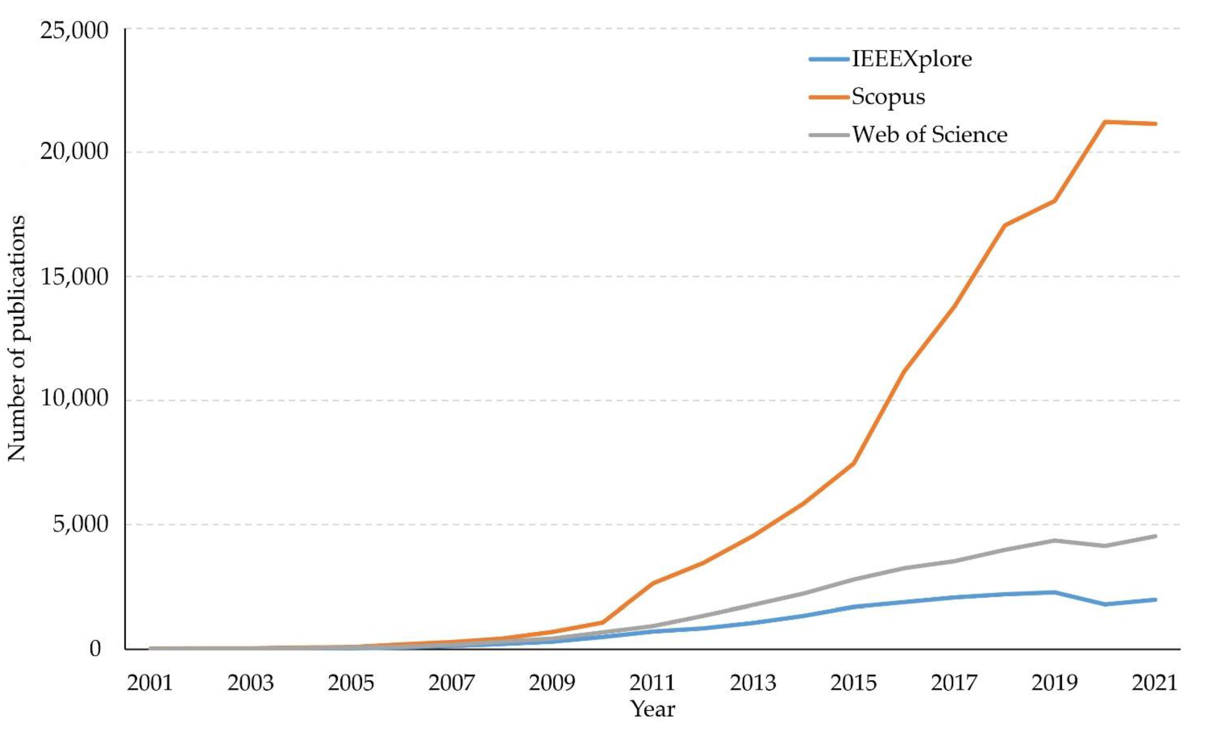
Figure 1. Number of publications dealing with energy harvesting (based on available metadata of publications).
Sustainability 14 16670 g001
Figure 2. Power ORing scheme (the abbreviations are based on generally known labeling).
Sustainability 14 16670 g002
Figure 3. Multiple input boost converter scheme—serial form (the abbreviations are based on generally known labeling).
Sustainability 14 16670 g003
Figure 4. Multiple input boost converter scheme—magnetic form (the abbreviations are based on generally known labeling).
Sustainability 14 16670 g004
Figure 5. Multiple input boost converter scheme—special design (the abbreviations are based on generally known labeling).
Sustainability 14 16670 g005
Figure 6. Multiple input boost converter scheme—parallel form (the abbreviations are based on generally known labeling).
Sustainability 14 16670 g006
Figure 7. Linear regulator scheme (the abbreviations are based on generally known labeling).
Sustainability 14 16670 g007
Figure 8. Switched capacitors scheme (derived from a general scheme of a two port network published, e.g., in [77]; the abbreviations are based on generally known labeling).
Sustainability 14 16670 g008
Figure 9. Shared inductor scheme (the abbreviations are based on generally known labeling).
Sustainability 14 16670 g009
Publisher’s Note: MDPI stays neutral with regard to jurisdictional claims in published maps and institutional affiliations.