Article

Artificial-Intelligence-Based Open-Circuit Fault Diagnosis in VSI-Fed PMSMs and a Novel Fault Recovery Method

by
Khaled A. Mahafzah
1,*,
Mohammad A. Obeidat
1,2,
Ayman M. Mansour
3,4,
Ali Q. Al-Shetwi
5 and
Taha Selim Ustun
6,*
1
Department of Electrical Engineering, Faculty of Engineering, Al-Ahliyya Amman University, Amman 19328, Jordan
2
Department of Electrical Power and Mechatronics Engineering, College of Engineering, Tafila Technical University, Tafila 66110, Jordan
3
Department of Computer and Communications Engineering, College of Engineering, Tafila Technical University, Tafila 66110, Jordan
4
Faculty of Computer Studies, Arab Open University (AOU), Amman 11953, Jordan
5
Electrical Engineering Department, Fahad bin Sultan University, Tabuk 71454, Saudi Arabia
6
Fukushima Renewable Energy Institute, AIST (FREA), Koriyama 963-0298, Japan
*
Authors to whom correspondence should be addressed.
Sustainability 2022, 14(24), 16504; https://doi.org/10.3390/su142416504
Submission received: 3 October 2022 / Revised: 30 November 2022 / Accepted: 6 December 2022 / Published: 9 December 2022
(This article belongs to the Special Issue Smart Grid and Power System Protection)

Abstract

:
Artificial intelligence (AI) techniques are widely used in fault diagnosis because they are superior in detection and prediction. The detection of faults in power systems containing electronic components is critical. The switch faults of the voltage source inverter (VSI) have a severe impact on the driving system. Short-circuit switches increase the thermal stress due to their fast and high stator currents. Additionally, open-circuit switches cause unstable motor operation. However, these issues are not sufficiently addressed or accurately predicted for VSI switch faults in the literature. Thus, this paper investigates the use of different AI classifiers for three-phase VSI fault diagnosis. Various AI methods are used, such as naïve Bayes, support vector machine (SVM), artificial neural network (ANN), and decision tree (DT) techniques. These methods are applied to a VSI-fed permanent magnet synchronous motor (PMSM) to detect the faults in the inverter switches. These methods use the drain–source voltage and PWM signals to decide whether the switch is healthy or unhealthy. In addition, they are compared in terms of their detection accuracy. In this regard, the comparative results show that the DT method has the highest accuracy as compared to other methods in the fault diagnosis process. Moreover, this paper proposes a novel and universal voltage compensation loop to compensate for the absence of the voltage portion due to the open switch fault. Thus, the driving system is assisted in operating under its normal operating conditions. The universal term is used because the proposed voltage compensation loop can be implemented in any type of inverter. To validate the results, the proposed system is implemented using two software programs, LTSPICE XVII-USA, WEKA 3.9-New Zealand.

1. Introduction

Permanent magnet synchronous motors (PMSMs) have some attractive characteristics, such as their high reliability and efficiency, robustness and compactness, which make them very popular machines in the industry and in power systems [1,2]. To obtain these attractive features of PMSMs, the driving system must be as reliable as possible. Thus, inverters are essential players in driving these motors [3,4]. However, the reliable operation of these inverters improves the reliability of the power grid and the PMSMs [5].
In smart grids, inverters are used for various reasons [6]. When an inverter is operated at high frequencies for an extended period of time, it is vulnerable to serious heat generation and loss issues, which can result in switching device failures such as short-circuit and open-circuit faults, which account for the majority of motor drive system failures [7]. Open-circuit faults have less of an effect on the motor itself and can be detected easily using different techniques. Short-circuit faults are rapid and hard to detect, meaning a protection circuit is required to avoid their impact on the motor drivers. Hence, the motor should be stopped when a short-circuit fault occurs and repair will be needed. The detection of these faults is covered in many papers with different techniques, such as in [8,9]. Fault diagnosis in PMSM driving systems has been paid more attention in recent years. Different methods have been proposed for this purpose in recent years. For instance, the signal-based open switch fault detection method was proposed in [10,11]. In these two studies, due to the use of a complex mathematical model, they employed more hardware devices (in addition to voltage and current measuring systems), such as FPGAs in [10] and magnetic coupling elements in [11]. Therefore, their systems cost more, which means these methods are not preferable for the industry. Another current-signal-based method was proposed in [12]. This method can effectively detect a fault if the inverter current is not balanced (detecting the neutral current of the three-phase inverter). However, this method becomes more complex when using a high multilevel inverter (e.g., above seven levels). In [13,14], new systems were proposed to detect both mechanical and electrical faults (open-circuit faults in PMSM driving systems). The proposed systems are sensors-based. Both systems have a degree of complexity, even during hardware installation or software implementation. However, neither method involves any driving system recovery techniques.
In [15,16], machine learning techniques were applied to detect abnormalities in a power system, such as symmetric and asymmetric faults. In these studies, a real power system dataset was collected and divided into training and testing datasets with different percentages. The accuracy of the proposed system was high, and it was compared with different artificial intelligence (AI) techniques. However, in order to reduce the complexity and number of malfunctions and failures due to the use of large measuring systems with the conventional fault diagnosis methods, AI methods were introduced for driving system fault diagnosis. In recent years, various AI algorithms have been applied to detect faults, and they have shown their usefulness in fault detection and identification. For instance, the authors in [9] proposed a method to detect open-circuit faults using Park’s vector average current method; then, they applied a fuzzy logic technique to obtain information regarding faulty VSI switches. The results for this method were compared with open-circuit detection methods. In [17], a combinational logic-based and fuzzy logic system was proposed for fault diagnosis. This method has some merits; it is simple to apply and it has good accuracy in the diagnosis procedure, but it must be combined with an intelligence redundancy engagement system. Moreover, the presented method is limited to detecting only open switch faults.
In [18], a neural network algorithm was generated for fault diagnosis and fault placement detection. The paper proposed a multiclass neural network algorithm in which a very careful design for input/output spaces was considered. Moreover, the torque, voltage, and current signals were used in this algorithm. The results revealed that the fault diagnosis methods integrated with ANNs are very effective and useful. However, a very complicated mathematical model is required to deal with the proposed methods, making them very complex and limited their applications. Moreover, the authors in [19,20] used a neural network algorithm based on stator current sensors. The main advantage of the proposed algorithm is that it is very fast compared to the conventional current sensors that are used in such applications. However, the system has two algorithms: the first for PMSM control and the second for the NN algorithm for fault detection.
Additionally, in contrast to the method proposed in this paper, the proposed fault detection algorithms in the literature are not able to recover the driving system to its normal operating conditions.
AI methods are among the advanced methods used for processing data and deriving special rules between datapoints [21]. They are utilized for demand response [22], generation control [23], and frequency stabilization purposes [24], as well as for fault diagnosis for PMSMS drives [25]. However, to date, the literature lacks studies on the use of other methods. Recently, fault diagnosis in PMSM driving systems has been paid more attention. When an inverter is operated at high frequencies for an extended period of time, it is vulnerable to serious heat generation and loss issues, which can result in switching device failures such as short-circuit and open-circuit faults. Open- and short-circuit faults have severe impacts on the system. Thus, detecting and solving these problems reduces the stop periods for the inverter-fed PMSM system and the repair costs. Under open-circuit fault conditions, the PMSM driving system is operated from a backup inverter. This increases the cost and volume of the driving system.
The inverter and motor winding are connected in series. An open-circuit fault will result in a large torque ripple or even braking torque because the motor output will produce a serious torque gap. On the other hand, a short-circuit fault will cause the power supply voltage to act directly on both ends of the winding, forcing the fault phase current to increase at an extremely high speed. In order to preserve the safety and dependability of the complete motor drive system, it is crucial to diagnose inverter problems and develop the necessary fault-tolerant solutions accurately.
The proposed fault detection algorithms in the literature are not able to recover the driving system to its normal operating conditions. Therefore, a novel and universal voltage compensation method is proposed in this study to recover the drive system to its typical working conditions. The proposed recovery system is very simple to apply and can eliminate the use of the current protection systems.
The use of artificial intelligence greatly contributes to finding the hidden relationships between the states of the inverted switch and the condition associated with the failure. Such relationships can only be known using artificial intelligence algorithms that are able to discover the hidden relationships and links between inputs and outputs.
AI algorithms are used in driving fault diagnosis, such as naïve Bayes, support vector machine (SVM), and decision tree (DT) algorithms. Thus, this paper applies different AI machine learning techniques to detect and classify the faults that may occur in three-phase VSI switches. The artificial intelligence system classifier is implemented based on measured switches voltages, PWM signals, and phase angles. Then, the measured data are processed using the AI technique to detect the faulty switch and determine whether it is an open- or short-circuit fault. When an open fault switch has occurred, a portion of the DC voltage is lost during the open switch malfunction. Therefore, a novel and universal voltage compensation method is proposed in this study to recover the drive system to its typical working conditions. Its universal nature means it is applicable to any type of inverter. This method makes use of AI to identify the facts about the malfunctioning switch. Then, this decision is used with a voltage compensation loop to trigger the selector switch to be connected to the right phase. The proposed recovery system is very simple to apply and can eliminate the use of the current protection systems.
This paper proceeds as follows. Section 1 discusses the literature review of the PMSM, its driving system, and the inverter fault detection methods. Section 2 discusses and simulates the proposed system. Section 3 presents the use of different AIs methods in fault detection and outlines the accuracy of each method. Section 4 presents the proposed voltage compensation method to recover the driving system to its normal operating conditions. Finally, Section 5 concludes the paper.

2. PMSM Driving System under Different Operating Conditions

Figure 1 illustrates the system under study. It comprises a permanent magnet synchronous motor (PMSM) stator fed by a two-level, three-phase inverter. The series RL branch replaces the stator side of the PMSM. The rotor of the PMSM is excluded due to its mechanical behavior. The two-level inverter is built from six N-channel MOSFETs with internal parasitic diodes (numbered from M1 to M6), where each switch has its own gate signal (control signal).
Moreover, and for simplicity, a sinusoidal pulse width modulation (SPWM) process is used to generate the gating signal for each specific switch. The control signal can be generated by comparing three sine waves with a 120° phase shift between them and with a sawtooth signal (carrier signal). Each sine wave has a frequency equal to the synchronous speed of the PMSM. At the same time, the carrier signal is generated at the switching frequency. Table 1 shows the selected parameters in the simulation. The simulation results are carried out using LTSPICE software. This software provides a real component’s datasheet in the simulation. The system is run for 2 s to avoid any transient period, and the selected solver is the normal one. The integration method is set to the modified trap (modified trapezoidal) method because this method removes the traditional ringing in the trapezoidal integration method at the same speed and accuracy as the trap method (trapezoidal method).

2.1. Normal Operating Conditions

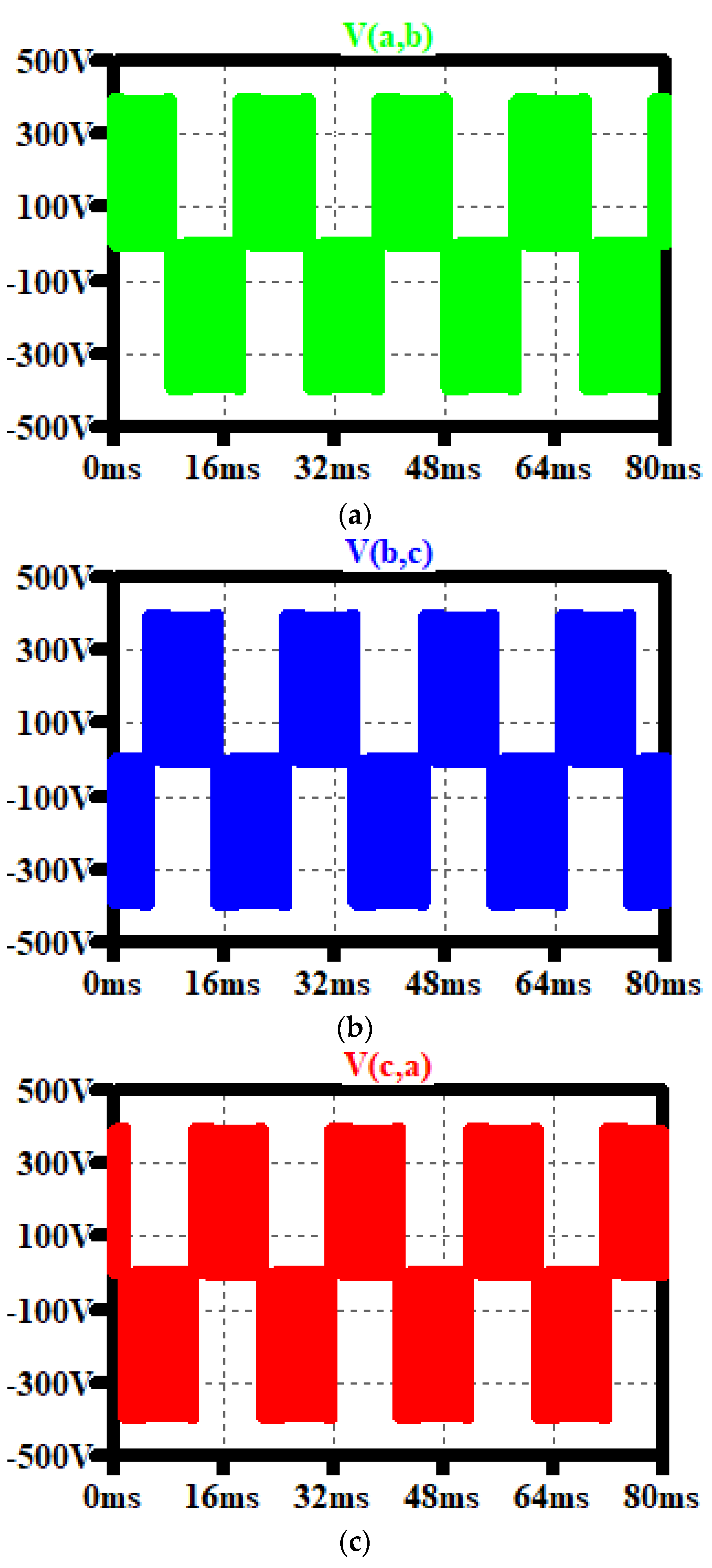
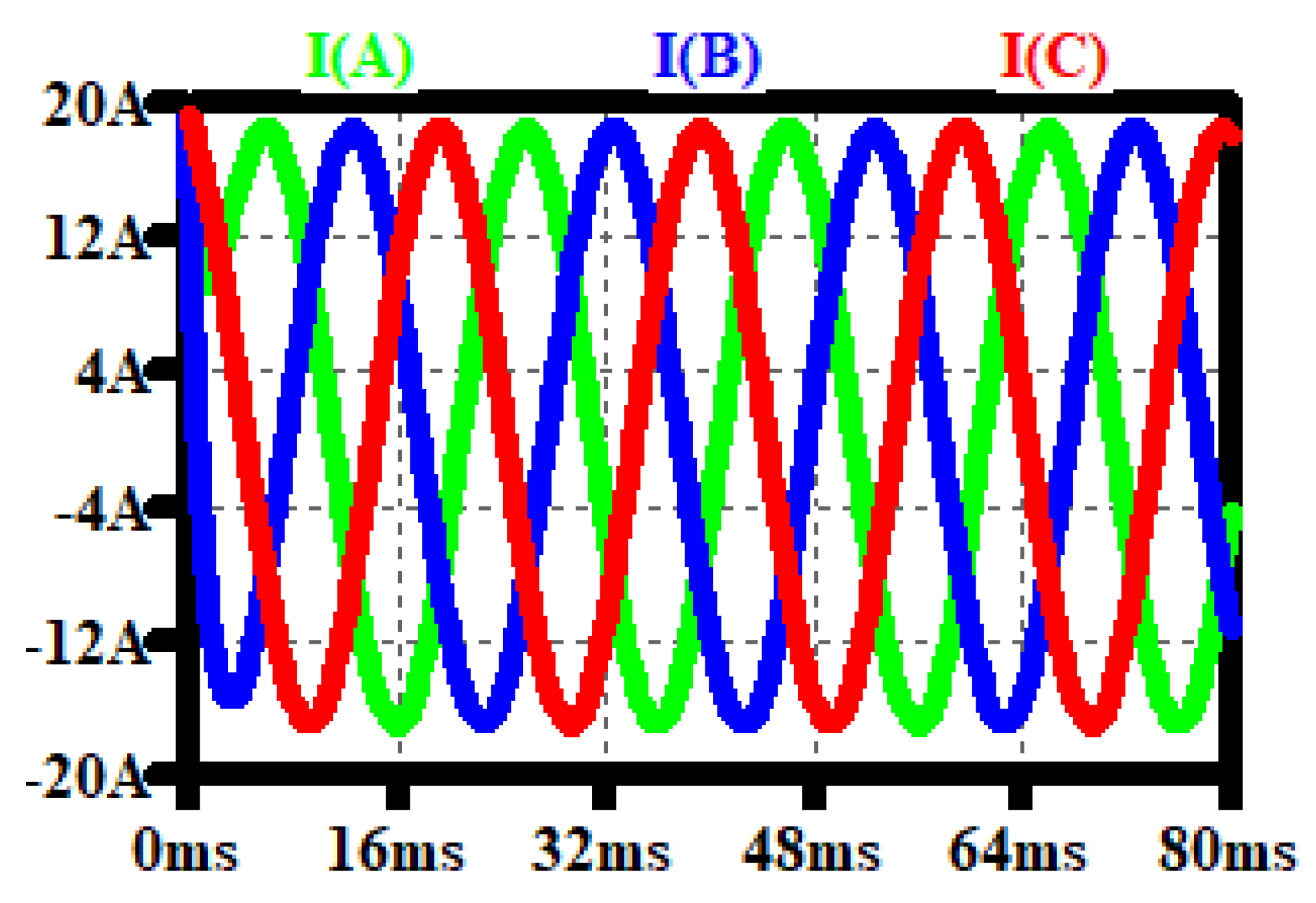
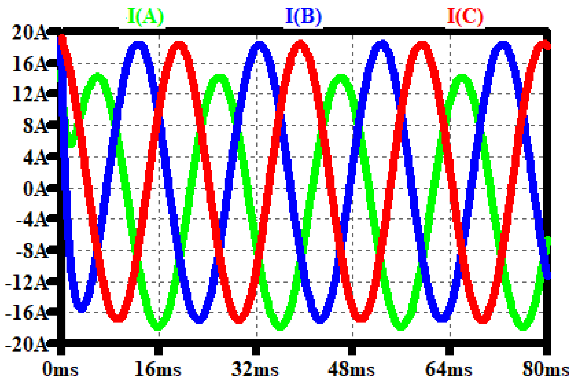
When the driving system operates under normal conditions, it supplies the three-phase stator line voltages between ab, bc, and ca, as seen in Figure 1 and Figure 2. The three-phase stator line voltages have a squire shape (averaging these squire voltages results in a sinusoidal voltage waveform.) In addition to the voltage, the inverter’s output current has a sinusoidal waveform. The stator inductance filters the output current of the inverter. This can be seen in Figure 3. Additionally, at the zero timepoint, the PMSM starts consuming the current; thus, the transient in the current shape appears for a while. However, the line current becomes more stable.
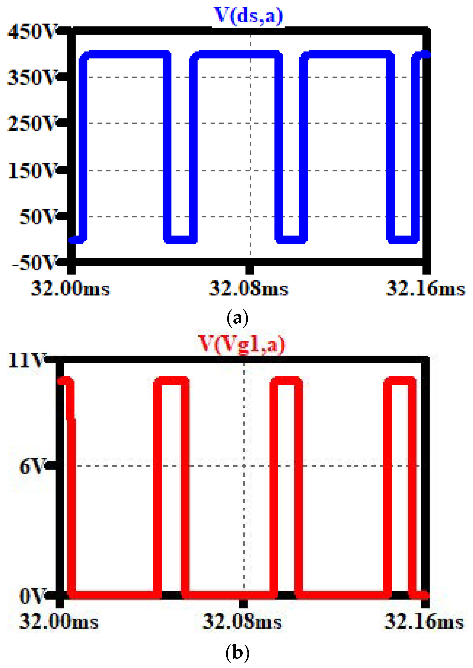
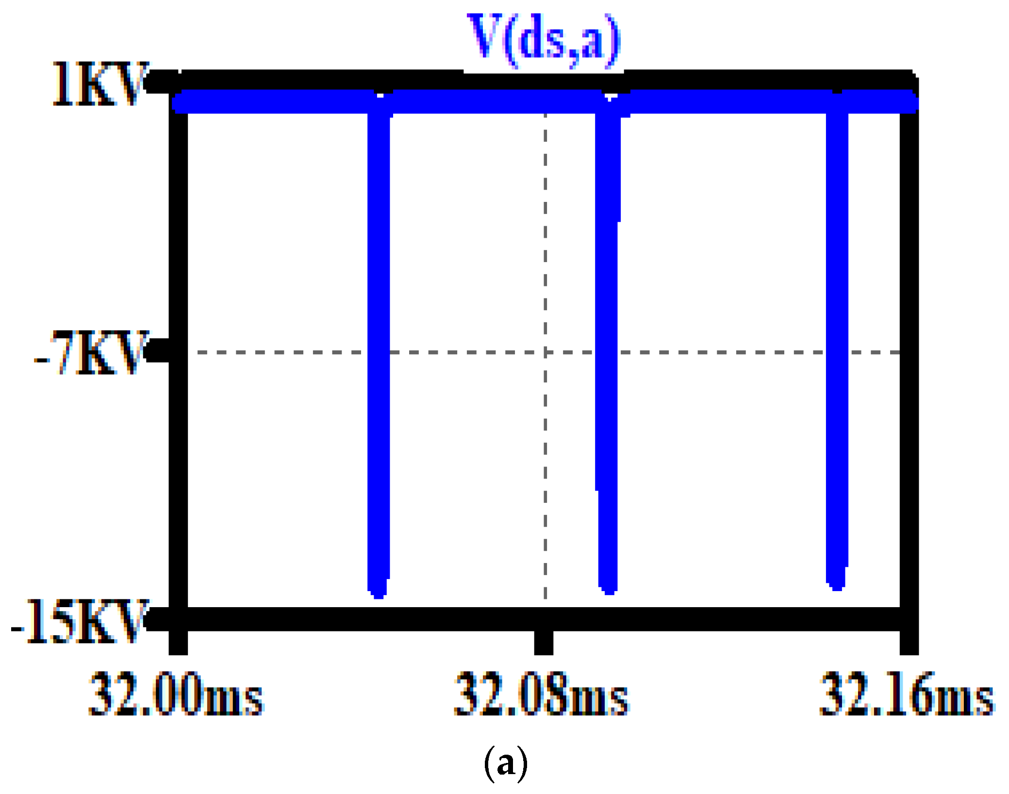
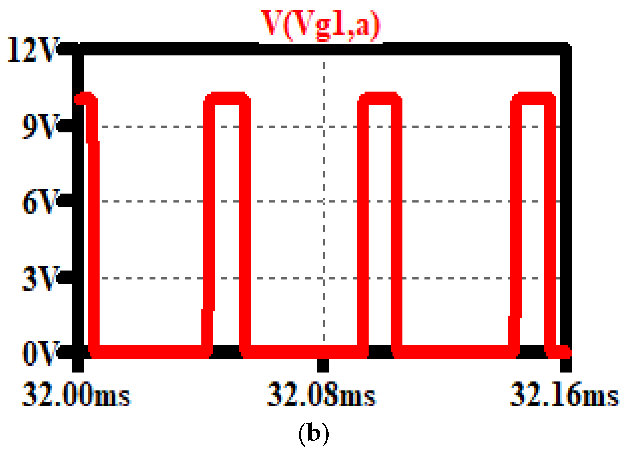
Figure 4a shows the drain to the source voltage across M1 and Figure 4b shows the M1 gate to the source voltage. As long as the Vgs is high, the M1 switch is conducting the current through its channel. Thus, Vds must be low (only the voltage drop can be seen across the switch terminal). The other switches in the inverter show the same behavior during normal operating conditions.

2.2. Open Switch Fault

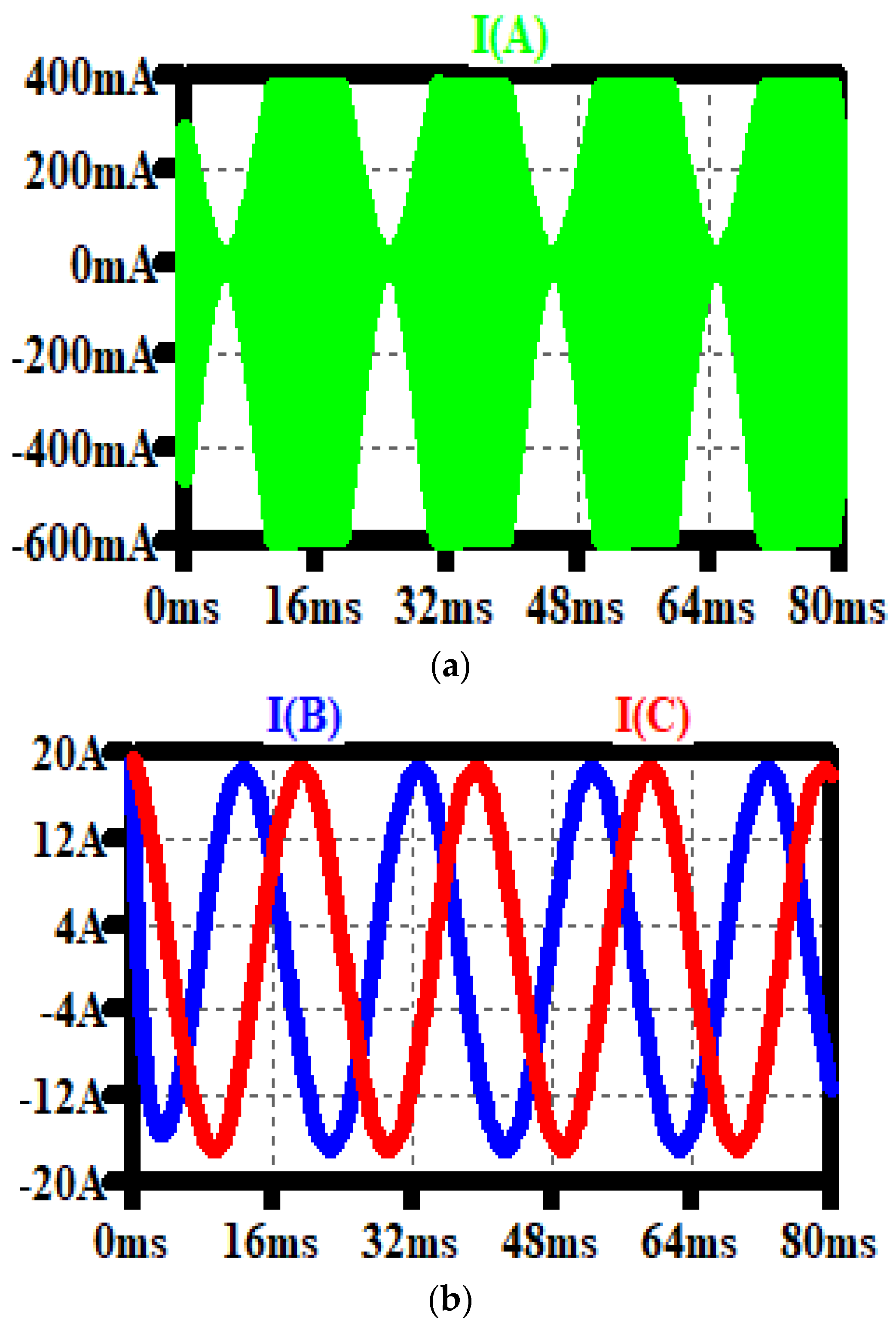
If one switch of the inverter is opened during the operation, the related PMSM phase will be disconnected from the DC power supply. However, the current is decreased to a very low range, as illustrated in Figure 5a (line current with fault) and Figure 5b. In Figure 1, the switch M1 is replaced by a 100 kΩ resistor to simulate the open switch fault. The other line current behaves as a normal current.
Figure 6a,b give a deeper view of the open switch fault (M1 in this case; see Figure 1). As seen from the figure and during this fault type, the drain to source voltage of M1 is high when the PWM (in red) is high. Moreover, there is a huge spark at the turn-on time. Due to this spark, the current change is resisted by the PMSM stator’s inductance.

2.3. Short Switch Fault

If one switch of the inverter is shorted out during the operation, the related PMSM phase will be continuously connected to the DC power supply. However, the current will be increased to a high range, as illustrated in Figure 7a. In Figure 7a, the switch M1 (see Figure 1) is replaced by a 0.1 Ω resistor to simulate the shorted switch fault. The other line currents are not affected when M1 is shorted out (see Figure 7b). Figure 8a shows that the drain-to-source voltage of M1 is low when the PWM, as shown in Figure 8b, is low.

3. AI Methods and System Classifiers

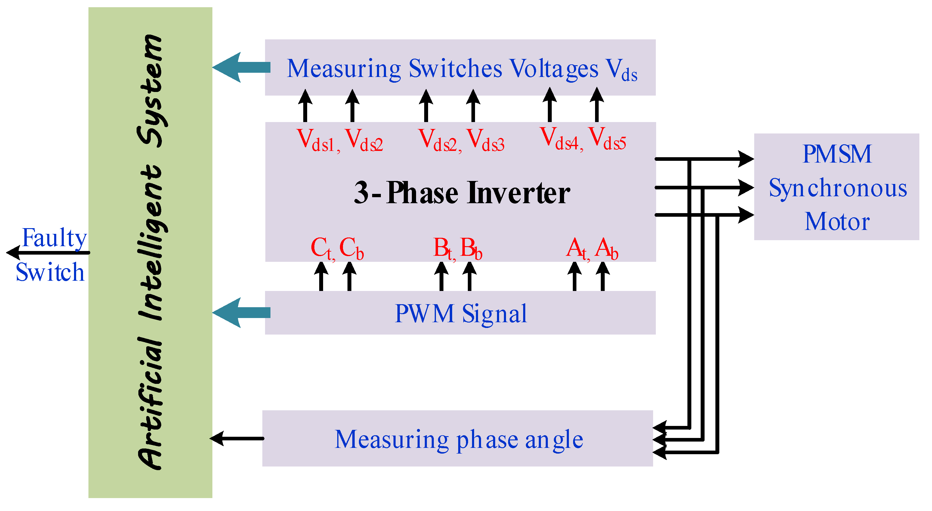
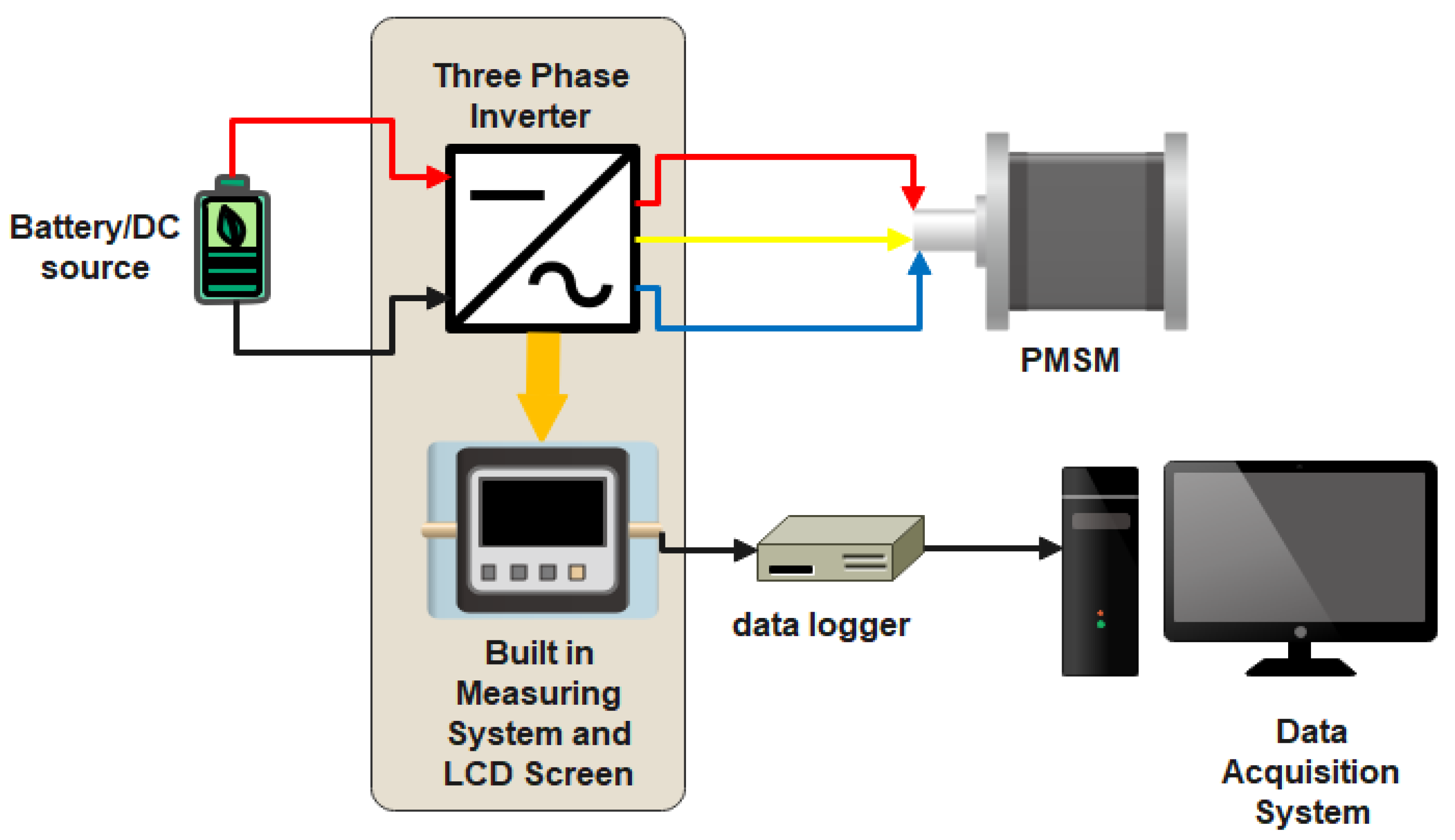
The proposed system shown in Figure 9 consists of the three-phase VSI-fed PMSM, AI system classifier, and measuring units for the switches voltages, PWM signals (high (logic 1)/low (logic 0)), and phase angle. Figure 10 illustrates the system under testing. It shows the inverter block containing a built-in measuring unit. This unit is able to measure the three-phase output voltages, line currents, power factor, and total harmonics distortion (THD). The measured data are recorded using a data logger and then the data acquisition system is used to analyze it. The drain-to-source voltage of each switch is not directly measured because Kirchhoff’s voltage loop can simply estimate it. In more detail, the current loop should contain a DC supply, one upper switch (M1, M3, M5), one lower switch (M4, M6, M2), and the stator impedance. Therefore, The AI system can decide if there is a faulty switch during the voltage loop. These measuring devices detect the phase voltage of the inverter output. Therefore, from the difference between the two-phase voltages, it is easy to detect the switch voltage based on the voltage loop. Regarding the PWM signals, the FPGA performs this job. It senses the width, peak, and shift between the pulses of the different switches. The sensed values are used for AI training using interfacing between the AI and FPGA systems.
In this system, the data for switch voltages Vds1 to Vds6, PWM signals p1 to p6, and the phase angle theta are collected and input using an AI technique to detect the faulty switch and determine whether it is an open- or short-circuit fault. The output for each technique is collected. The accuracy of each technique is measured to decide the best AI method for the proposed system.

3.1. Naïve Bayes Classifier

The Bayesian classifier model assumes separated properties with different values, so changing any property value does not affect the other values. This method is considered a very fast algorithm for classifications, which can be used for real-time classifications. The Bayesian algorithm starts by detecting one class out of N classes, and then the maximum probability for a given set of m data inputs for all possible values in the class is selected.
Step 1 involves selecting the class number N using Equation (1):
C N = a r g m a x P c l a s s | d a t a
where the data d have m variables d = d1, d2, d3, …, dm, which are given by:
d = P d a t a | c l a s s P c l a s s P d a t a
where P(.) is also called the class probability and P (|) is called the conditional probability. By dropping the denominator, as the denominator remains constant for a given input, we can remove that term:
C N = a r g m a x P d a t a | c l a s s P c l a s s

3.2. Support Vector Machine (SVM)

A SVM is a linear classifier that depends on choosing an optimal hyperplane, such that the distance between the closest vectors of two classes and the suggested hyperplane is the maximum. This method is highly recommended over feedforward artificial neural networks for solving complex problems consisting of high dimensions and large data without overfitting.

3.3. Artificial Neural Network

This method consists of multiple layers with a set of neurons. It has three main layers, the input, hidden, and output layers. The connection between any two layers has a weight value, and the output layer uses a linear or non-linear function based on the problem’s complexity. In this method, the designer can increase the number of hidden layers for fast and more accurate models.

3.4. Decision Tree

A decision tree divides an input space into a group of mutually exclusive regions by giving each region its own label. A decision tree is made up of root nodes and inner nodes. To perform the classification, one way of separating the data for the different categories is to measure the percentage of impurities in the root nodes. The most famous of these methods is the entropy measure:
E t = φ p 1 , p 2 , p j j = 1 J p j l o g 2 p j
where p j = P j | t , t h e   p r o b a b i l i t y   r e l a t i v e   f r e q u e n c y   o f   c l a s s j a t n o d e t
The entropy measures the homogeneity of a node. The maximum entropy value (log nc) is obtained when the records are evenly distributed.
Similarly, the impurity measure of a tree T can be expressed as:
E T = t Ψ n t n E t
where Ψ is the set of terminal nodes in the tree T, nt is the number of records at child t, and n is the number of records at the terminal node. The information gain is calculated as in Equation (6):
G A I N S p l i t = E P E T = E P i = 1 k n i n E i
where the parent node P (non-leaf node, node with partition) is split into k partitions (children), ni is the number of records in the partition i, and n is the number of records at the terminal node. Figure 11 shows the developed decision tree model based on the data from Table 2. It is important to mention that H means healthy and NH means non-healthy.
Table 2 is created based on the possible stator current loops of the PMSM, or in other words the possible combinations between VSI switches that form the current loop. It consists of the pulse width modulation signals for all switches, switch statuses (drain–source voltage Vds values for all switches), and operation time periods. For example, when the theta is between 0 and 60°, then line a is in positive polarity, while both lines b and c provide the return bath of the stator current. Based on the normal operation of the VSI, Table 2 is filled out. Moreover, the P, Vds, and theta columns are the input parameters for the different AI methods. The AI algorithm provides the monitor with the expected decision, as clarified in the last column (green column).
The developed model has been clarified in the manuscript as requested. The data used in the system development process are divided into three groups, a training group, a testing group, and a validation group. The data are processed at an initial stage to extract features and reduce the dimensions of these features after identifying a set of influencing factors.
The resulting features are then used to train the system to obtain the basic attributes of the phase model, which is the backbone of the classification system. The ability of the proposed system to classify the data with high efficiency and accuracy is ensured. If the required accuracy is not obtained, the features and influence factors are indicated, and the factors are re-defined until the best ready-to-use model is reached.
Here, the used symbols in Table 2 P1–P6 are the PWM signals for all switches; NZ is not zero; Z is zero; OC means the open-circuit fault; the included number relates to the switch number from Figure 1; L1–L3 are positive half periods of phases A, B, and C; and L5–L6 are negative half periods of phases A, B, and C, respectively.
Table 3 shows a comparison between the different AI classifier methods. The decision tree (DT) provides the best evidence among the other methods. It achieves 99% accuracy, making it the most accurate method. Moreover, it has the lowest possible classification time as compared with other methods. Additionally, this method has the lowest training time as compared with other methods. In contrast, the lowest accuracy is recorded for the naïve Bayes method (25%), with the slowest classification time (0.03 s).
The artificial neural network (ANN) is the fastest method for classifying the data. This can be seen from its classification time of 0.01 s. However, it has relatively low accuracy of about 37.5%. In addition, the training time of this method is in the middle, between the other classification methods. Finally, the SVM method achieves the highest training time as compared to other methods. At the same time, it has a good accuracy rate of about 75% and has the fastest classification time of 0.01 s, the same as the ANN method.

4. The Proposed Voltage Compensation Method for Inverter Fault Recovery

The inverter and motor winding are connected in series. The open-circuit fault will result in a large torque ripple or even braking torque because the motor output will produce a serious torque gap. On the other hand, the short-circuit fault will cause the power supply voltage to act directly on both ends of the winding, forcing the fault phase current to rise at an extremely high speed. In order to preserve the safety and dependability of the complete motor drive system, it is crucial to diagnose inverter problems and develop the necessary fault-tolerant solutions accurately. There are several methods that can be used to detect inverter switch faults. One of them involves using AI methods [26,27,28,29]. This section presents the proposed method that can be used to overcome the inverter faults and recover normal system operation.
Previous studies presented a fault-tolerant control technique for cascaded, two-level, inverter-driven, open-end winding permanent magnet synchronous motors [26,27,28] as a fault treatment method. Under open-circuit faults, the PMSM driving system is operated from a backup inverter. This increases the cost and volume of the driving system. In [26,27,28,29], during the open-circuit fault, the topology can be changed to operate as a two-phase H-bridge inverter. Assuming phase A is under open-circuit fault conditions, the controller can disable the switch on the phase a bridge leg. In order to maintain the fault-tolerant topology, the topology can be changed to a two-phase H-bridge inverter, then the circular flux linkage trajectory can be rebuilt by altering the PWM modulation mode during the motor’s operation. Due to its higher redundancy, the multiphase motor driver is a popular topic of discussion in fault-tolerant control.
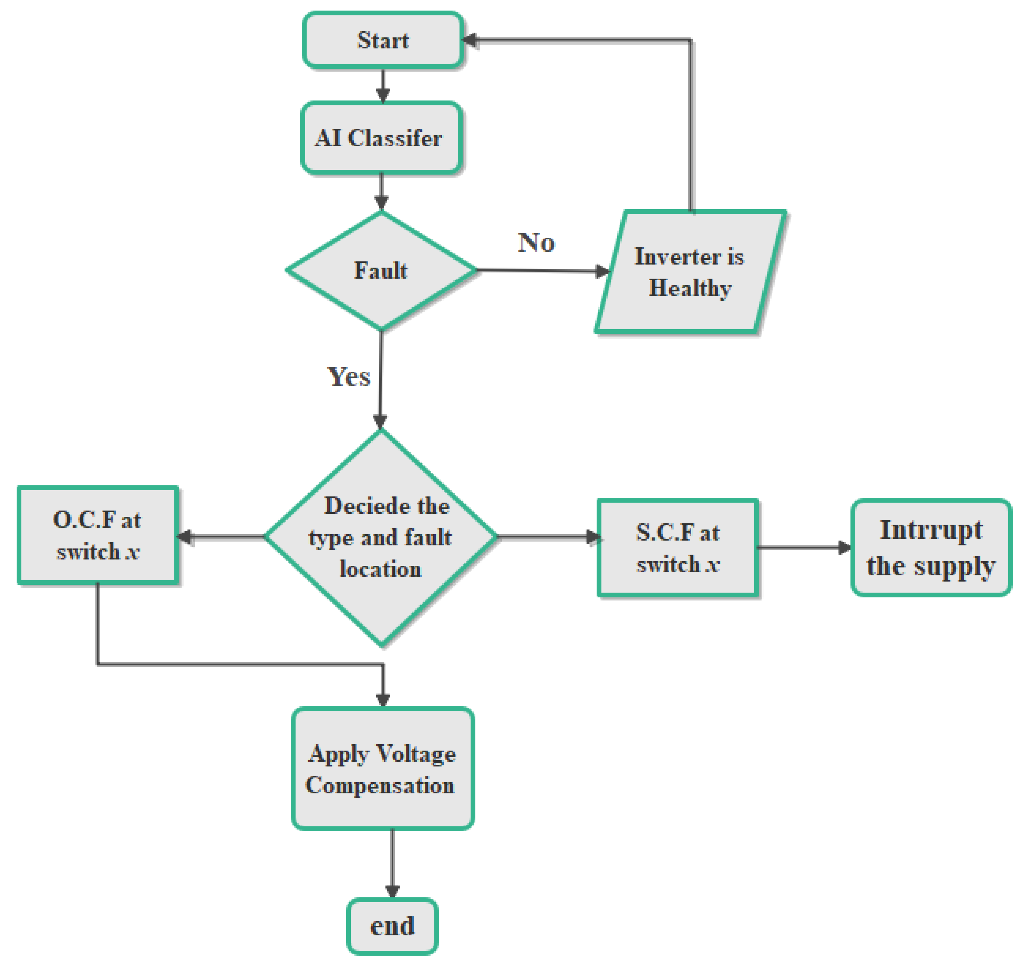
Figure 12 introduces a method for fault diagnosis and treatment. It shows the flow chart of the fault detection steps, determines the fault type, and then decides whether the situation requires a voltage compensation loop. The two types of faults can be treated as follows:
  • Short Circuit Fault of the Inverter Switch: To overcome a short-circuit fault of any switch inverter, it is possible to connect fuses at the coupling point between the inverter legs and the PMSM stator windings. Thus, the fuse will burn out in case of a short-circuit current and the motor operation will stop immediately.
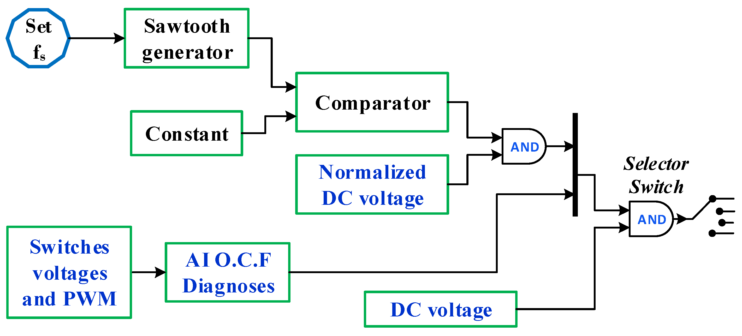
  • Open-Circuit Fault of the Inverter Switch: If any switch is opened, a part of the current line is missed. Therefore, part of the DC voltage is lost. This section proposes a voltage compensation method to recover the driving system to its normal operating conditions. In this method, the faulty switch’s information is determined using AI. Then, this signal is processed by sending a trigger signal to a selector switch. The selector switch is shifted to a position to compensate for the missing part of the voltage supply. This voltage is chopped using a voltage-controlled oscillator (VCO). The oscillation frequency is set as the switching frequency.
The voltage compensation method is illustrated in Figure 13. When the open-circuit fault attacks any inverter switch, the decision comes from the AI method. The decision is used to trigger the selector switch to connect the compensation voltage loop instead of the faulty phase path. Meanwhile, the sawtooth signal has a switching frequency equal to the inverter switching frequency and is compared with a constant value to generate a chopped voltage compatible with the missing voltage. Then, this signal is connected to the stator terminal, which suffers from an open switch fault.
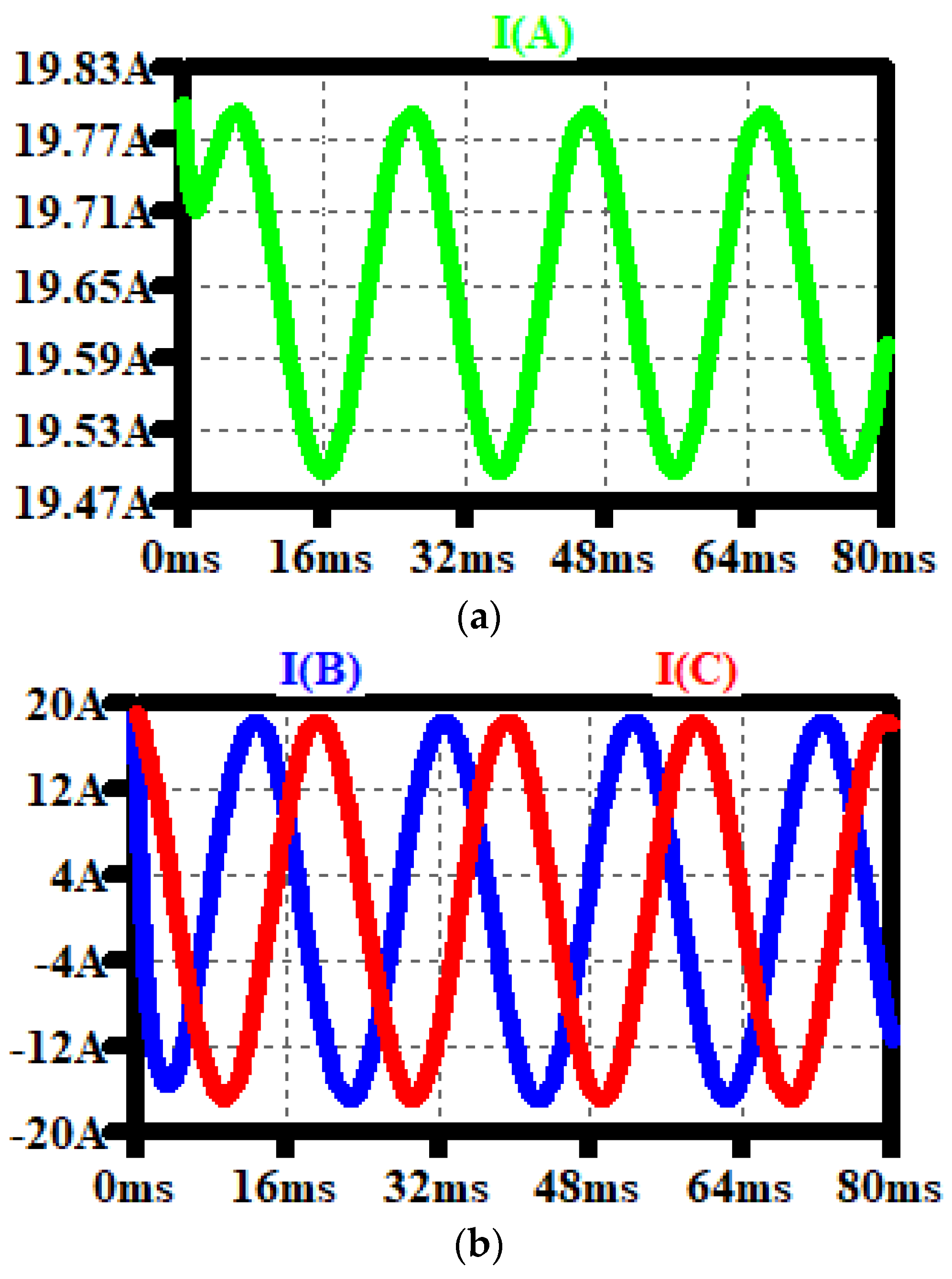
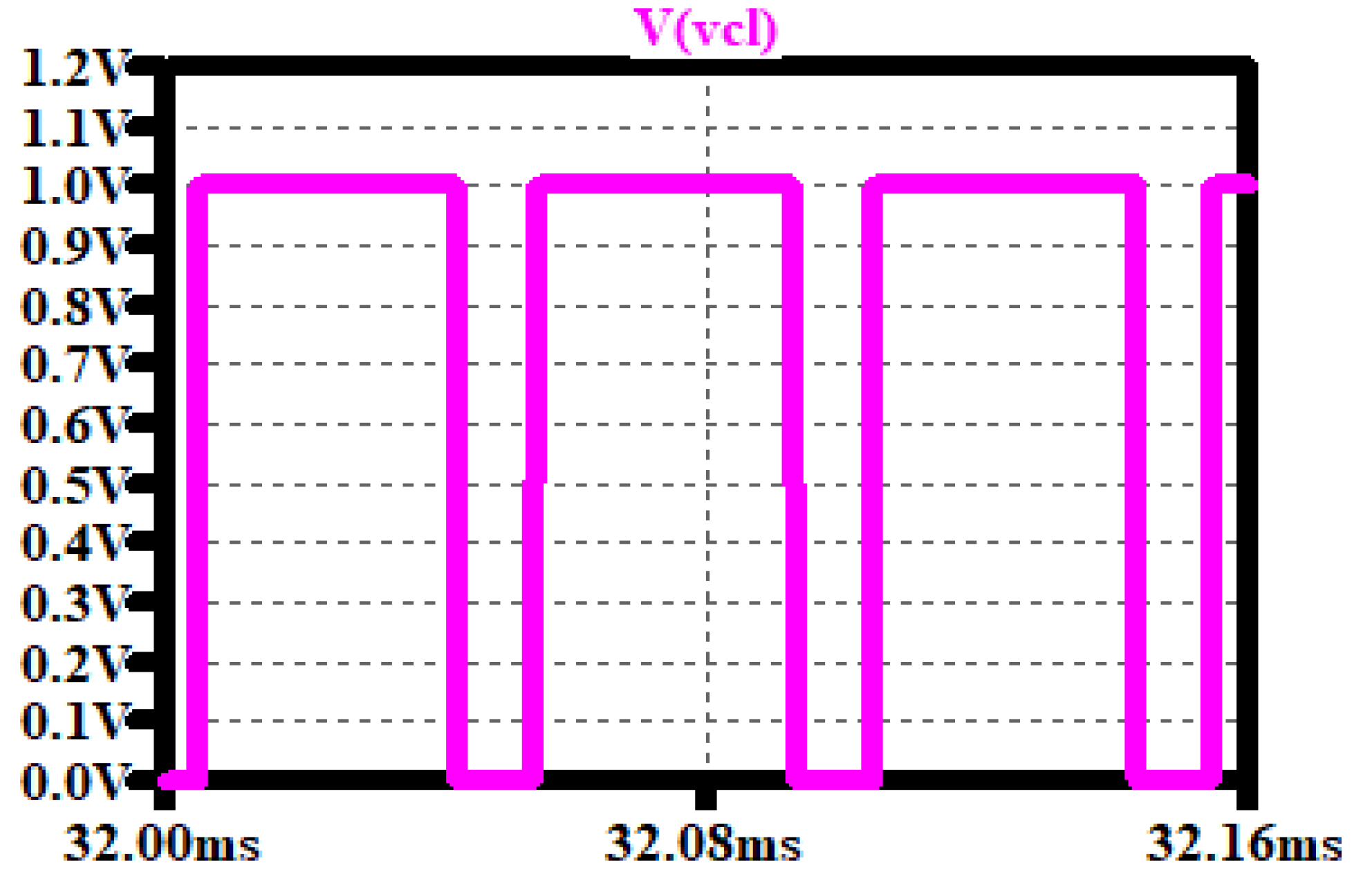
To verify the voltage compensation loop, it is assumed that switch M1 is a faulty switch. To simulate the open-circuit fault, the MOSFET is replaced by a 100 kΩ resistance, then the compensated voltage is connected to replace the faulty switch. The decision is made by the AI classifier. The normalized output of the voltage compensation loop is shown in Figure 14, whereas the three-phase stator currents of the PMSM are shown in Figure 15.
The output of the voltage compensation loop has the same pattern as the M1 switch’s drain–source voltage during normal operating conditions (see Figure 4). Moreover, as seen in Figure 15, the stator current of the faulty phase has a lower peak current, which is related to the use of the 100 kΩ resistance. This resistance causes a voltage drop, which reduces the peak of the stator current. However, the voltage compensation loop shows its effectiveness in open-circuit fault recovery.

5. Conclusions

In this study, we proposed using various AI techniques to diagnose switch faults in VSI-fed PMSMs. In VSI-fed PMSMs, the faults caused by open and short circuits significantly affect the system. Thus, detecting and fixing these issues reduces the stoppage periods for the inverter-fed PMSM system and lowers the repair costs. For efficient fault diagnosis, different AI techniques are used in this paper, such as naïve Bayes, support vector machine (SVM), artificial neural network (ANN), and decision tree (DT) techniques. All of these AI techniques are applied to detect the open- and short-circuit VSI faults, which are then compared. The comparison results show that the DT strategy has the highest accuracy (99%) as compared to the other methods. Moreover, the results show that it is the fastest method when comparing the training times, although it has a moderate classification time. The short-circuit fault is treated using a normal fuse, whereas the open-circuit switch fault is treated using the voltage compensation method. It is also important to mention that the novel voltage compensation loop compensates for the absence of a voltage portion due to an open switch fault. The proposed voltage compensation loop is a universal loop, which means it can be used in the driving system regardless of the VSI inverter type. Additionally, the compensation loop is simple to apply and uses a selector switch to connect the loop at the faulty phase. In this context, the AI decision is used to trigger the selector switch. The AI techniques must have the highest possible accuracy for the efficient operation of the proposed voltage compensation loop. For validation purposes, LTSPICE XVII and WEKA 3.9 were used to simulate the proposed systems.

Author Contributions

Conceptualization, K.A.M.; methodology, K.A.M. and M.A.O.; software, K.A.M. and A.M.M.; validation, M.A.O., A.Q.A.-S. and T.S.U.; formal analysis, K.A.M., M.A.O., A.Q.A.-S. and T.S.U.; investigation, A.Q.A.-S. and T.S.U.; writing—original draft preparation, K.A.M., M.A.O., A.Q.A.-S. and T.S.U.; writing—review and editing, K.A.M., M.A.O., A.M.M., A.Q.A.-S. and T.S.U.; project administration and funding acquisition, T.S.U. All authors have read and agreed to the published version of the manuscript.

Funding

This research received no external funding.

Conflicts of Interest

The authors declare no conflict of interest.

References

  1. Wang, Z.; Chen, J.; Cheng, M.; Chau, K.T. Field-oriented control and direct torque control for paralleled vsis fed pmsm drives with variable switching frequencies. IEEE Trans. Power Electron. 2016, 31, 2417–2428. [Google Scholar] [CrossRef]
  2. Jarzebowicz, L. Errors of a linear current approximation in high speed pmsm drives. IEEE Trans. Power Electron. 2017, 32, 8254–8257. [Google Scholar] [CrossRef]
  3. Matsui, K.; Kawata, Y.; Ueda, F. Application of parallel connected NPC-PWM inverters with multilevel modulation for AC motor drive. IEEE Trans. Power Electron. 2000, 15, 901–907. [Google Scholar] [CrossRef]
  4. Dyanamina, G.; Kakodia, S.K. Adaptive neuro fuzzy inference system based decoupled control for neutral point clamped multilevel inverter fed induction motor drive. Chin. J. Electr. Eng. 2021, 7, 70–82. [Google Scholar] [CrossRef]
  5. Cheng, F.; Yao, L.; Xu, J.; Chi, Y.; Sun, Y.; Wang, Z.; Li, Y. A comprehensive AC fault ride-through strategy for HVDC link with serial-connected LCC-VSC hybrid inverter. CSEE J. Power Energy Syst. 2022, 8, 175–187. [Google Scholar] [CrossRef]
  6. Ustun, T.S.; Hashimoto, J.; Otani, K. Impact of Smart Inverters on Feeder Hosting Capacity of Distribution Networks. IEEE Access 2019, 7, 163526–163536. [Google Scholar] [CrossRef]
  7. Alavi, M.; Wang, D.; Luo, M. Short-Circuit Fault Diagnosis for Three-Phase Inverters Based on Voltage-Space Patterns. IEEE Trans. Ind. Electron. 2014, 61, 5558–5569. [Google Scholar] [CrossRef]
  8. Lu, B.; Sharma, S.K. A Literature Review of IGBT Fault Diagnostic and Protection Methods for Power Inverters. IEEE Trans. Ind. Appl. 2009, 45, 1770–1777. [Google Scholar] [CrossRef]
  9. Masrur, M.A.; Chen, Z.; Murphey, Y. Intelligent diagnosis of open and short circuit faults in electric drive inverters for real-time applications. IET Power Electron. 2010, 3, 279–291. [Google Scholar] [CrossRef]
  10. Shahbazi, M.; Poure, P.; Saadate, S.; Zolghadri, M.R. FPGA-based fast detection with reduced sensor count for a fault-tolerant three-phase converter. IEEE Trans. Ind. Inform. 2012, 9, 1343–1350. [Google Scholar] [CrossRef]
  11. Nie, S.; Pei, X.; Chen, Y.; Kang, Y. Fault diagnosis of PWM DC–DC converters based on magnetic component voltages equation. IEEE Trans. Power Electron. 2013, 29, 4978–4988. [Google Scholar] [CrossRef]
  12. Duan, P.; Xie, K.G.; Zhang, L.; Rong, X. Open-switch fault diagnosis and system reconfiguration of doubly fed wind power converter used in a microgrid. IEEE Trans. Power Electron. 2010, 26, 816–821. [Google Scholar] [CrossRef]
  13. Chen, T.; Pan, Y.; Xiong, Z. A hybrid system model-based open-circuit fault diagnosis method of three-phase voltage-source inverters for PMSM drive systems. Electronics 2020, 9, 1251. [Google Scholar] [CrossRef]
  14. Huang, G.; Luo, Y.P.; Zhang, C.F.; Huang, Y.S.; Zhao, K.H. Current sensor fault diagnosis based on a sliding mode observer for PMSM driven systems. Sensors 2015, 15, 11027–11049. [Google Scholar] [CrossRef] [PubMed] [Green Version]
  15. Ustun, T.S.; Hussain, S.M.S.; Yavuz, L.; Onen, A. Artificial Intelligence Based Intrusion Detection System for IEC 61850 Sampled Values Under Symmetric and Asymmetric Faults. IEEE Access 2021, 9, 56486–56495. [Google Scholar] [CrossRef]
  16. Ustun, T.S.; Hussain, S.M.S.; Ulutas, A.; Onen, A.; Roomi, M.M.; Mashima, D. Machine Learning-Based Intrusion Detection for Achieving Cybersecurity in Smart Grids Using IEC 61850 GOOSE Messages. Symmetry 2021, 13, 826. [Google Scholar] [CrossRef]
  17. Chen, W.; Bazzi, A.M. Logic-Based Methods for Intelligent Fault Diagnosis and Recovery in Power Electronics. in IEEE Trans. Power Electron. 2017, 32, 5573–5589. [Google Scholar] [CrossRef]
  18. Chen, S.; Ge, H.; Li, J.; Pecht, M. Progressive Improved Convolutional Neural Network for Avionics Fault Diagnosis. IEEE Access 2019, 7, 177362–177375. [Google Scholar] [CrossRef]
  19. Jankowska, K.; Dybkowski, M. Design and Analysis of Current Sensor Fault Detection Mechanisms for PMSM Drives Based on Neural Networks. Designs 2022, 6, 18. [Google Scholar] [CrossRef]
  20. Skowron, M.; Orlowska-Kowalska, T.; Wolkiewicz, M.; Kowalski, C.T. Convolutional neural network-based stator current data-driven incipient stator fault diagnosis of inverter-fed induction motor. Energies 2020, 13, 1475. [Google Scholar] [CrossRef]
  21. Obeidat, M.A.; Mansour, A.M.; al Omaireen, B.; Abdallah, J.; Khazalah, F.; Alaqtash, M. A Deep Review and Analysis of Artificial Neural Network Use in Power Application with Further Recommendation and Future Direction. In Proceedings of the 2021 12th International Renewable Engineering IEEE Conference (IREC), Amman, Jordan, 14–15 April 2021; pp. 1–5. [Google Scholar] [CrossRef]
  22. Latif, A.; Paul, M.; Das, D.C.; Hussain, S.M.S.; Ustun, T.S. Price Based Demand Response for Optimal Frequency Stabilization in ORC Solar Thermal Based Isolated Hybrid Microgrid under Salp Swarm Technique. Electronics 2020, 9, 2209. [Google Scholar] [CrossRef]
  23. Farooq, Z.; Rahman, A.; Hussain, S.M.S.; Ustun, T.S. Power Generation Control of Renewable Energy Based Hybrid Deregulated Power System. Energies 2022, 15, 517. [Google Scholar] [CrossRef]
  24. Latif, A.; Hussain, S.M.S.; Das, D.C.; Ustun, T.S. Double stage controller optimization for load frequency stabilization in hybrid wind-ocean wave energy based maritime microgrid system. Appl. Energy 2021, 282, 116–171. [Google Scholar] [CrossRef]
  25. Yan, H.; Xu, Y.; Cai, F.; Zhang, H.; Zhao, W.; Gerada, C. PWM-VSI Fault Diagnosis for a PMSM Drive Based on the Fuzzy Logic Approach. IEEE Trans. Power Electron. 2019, 34, 759–768. [Google Scholar] [CrossRef]
  26. Restrepo, J.A.; Berzoy, A.; Ginart, A.E.; Aller, J.M.; Harley, R.G.; Habetler, T.G. Switching strategies for fault tolerant operation of single DC-link dual converters. IEEE Trans. Power Electron. 2011, 27, 509–518. [Google Scholar] [CrossRef]
  27. Correa, P.; Pacas, M.; Rodriguez, J. Modulation strategies for fault-tolerant operation of H-bridge multilevel inverters. In Proceedings of the 2006 IEEE International Symposium on Industrial Electronics, Québec, QC, Canada, 9–13 July 2006; Volume 2, pp. 1589–1594. [Google Scholar]
  28. Aleenejad, M.; Iman-Eini, H.; Farhangi, S. Modified space vector modulation for fault-tolerant operation of multilevel cascaded H-bridge inverters. IET Power Electron. 2013, 6, 742–751. [Google Scholar] [CrossRef]
  29. Mhiesan, H.; Wei, Y.; Siwakoti, Y.P.; Mantooth, H.A. A fault-tolerant hybrid cascaded H-bridge multilevel inverter. IEEE Trans. Power Electron. 2020, 35, 12702–12715. [Google Scholar] [CrossRef]
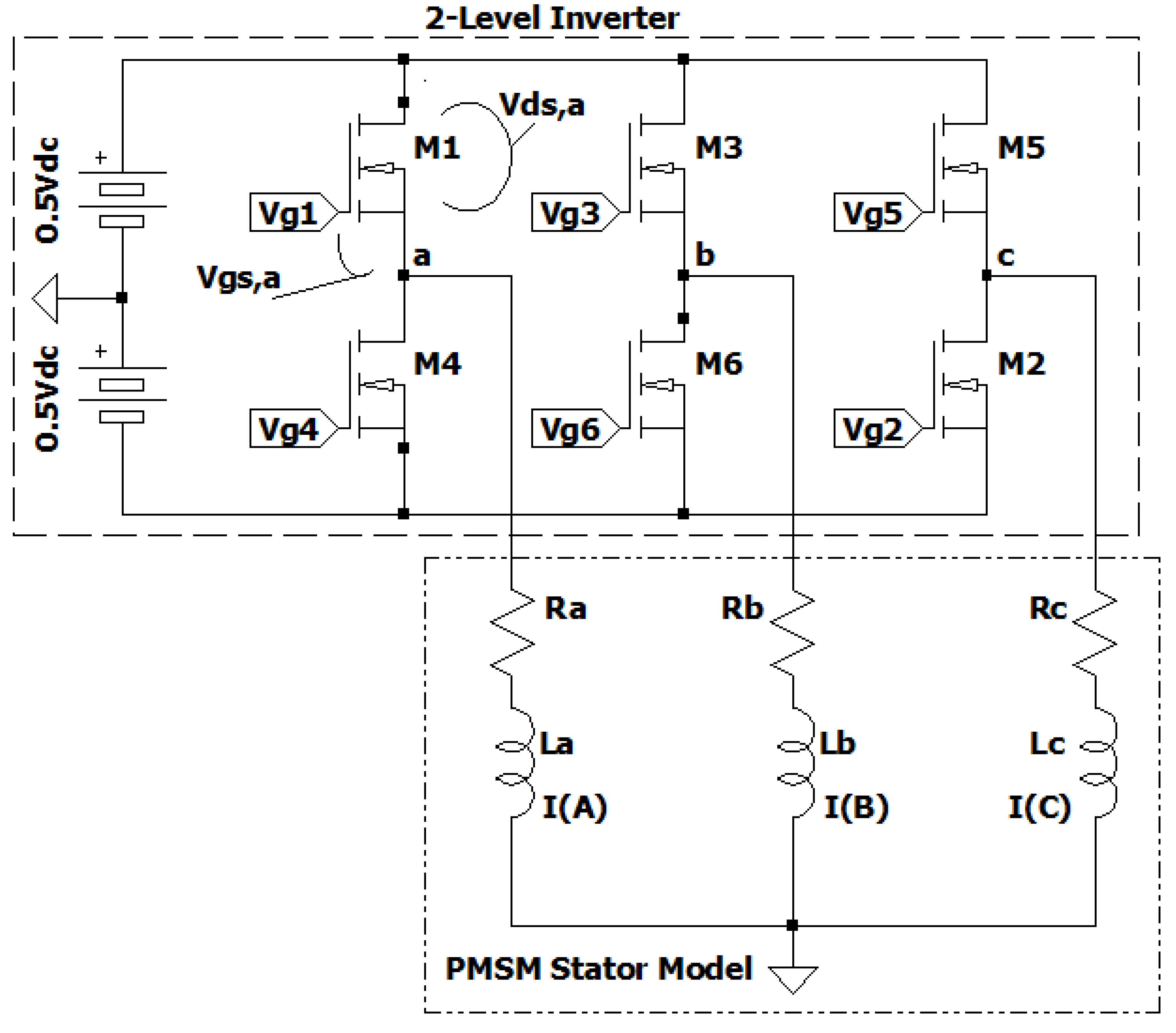
Figure 1. Six inverter switches in a three-phase driving system.
Sustainability 14 16504 g001
Figure 2. Line–line stator voltages (a): voltage between a-b, see Figure 1; (b): voltage between b-c, see Figure 1; (c): voltage between c-a, see Figure 1.
Sustainability 14 16504 g002
Figure 3. Three-phase stator line currents (see Figure 1).
Sustainability 14 16504 g003
Figure 4. (a) The M1 drain–source voltage (see Figure 1) in healthy conditions. (b) The M1 gate–source voltage (see Figure 1) in healthy conditions.
Sustainability 14 16504 g004
Figure 5. (a): Phase a current when M1 is an open circuit. (b): Phase b and c currents when M1 is an open circuit.
Sustainability 14 16504 g005
Figure 6. (a) The M1 drain–source voltage under open-circuit conditions. (b) The M1 gate–source voltage under open-circuit conditions.
Sustainability 14 16504 g006aSustainability 14 16504 g006b
Figure 7. (a) The stator line a current when M1 is a short circuit. (b) The stator line b and c currents when M1 is a short circuit.
Sustainability 14 16504 g007
Figure 8. (a) The M1 drain–source voltage under short-circuit conditions. (b) The M1 gate–source voltage under short-circuit conditions.
Sustainability 14 16504 g008
Figure 9. The proposed AI classifier system.
Sustainability 14 16504 g009
Figure 10. Inverter-fed PMSM with built-in measurement and data acquisition system.
Sustainability 14 16504 g010
Figure 11. Decision tree classification model.
Sustainability 14 16504 g011
Figure 12. The proposed AI classifier used for the fault detection method.
Sustainability 14 16504 g012
Figure 13. The proposed voltage compensation method.
Sustainability 14 16504 g013
Figure 14. Normalized output of the VCL.
Sustainability 14 16504 g014
Figure 15. Three-phase stator current when applying the VCL.
Sustainability 14 16504 g015
Table 1. Selected parameters for LTSPICE.
ParameterValue/Model
Input/Output Power4.5 kW
DC voltage Vdc400 V
Switching frequency fs20 kHz
PMSM stator frequency fm50 Hz
MOSFETIPB65R420CFD
Stator impedance of PMSM10 Ω, 10 mH
Open switch fault100 k Ω
Short switch fault0.1 Ω
Table 2. The possible combinations for the stator current loop and AI decision classifier for possible open switch faults.
Input Data for AI ClassifiersAI Classifier Output
P1P2P3P4P5P6ThetaVds1Vds2Vds3Vds4Vds5Vds6Decision of AI
110000L1ZZNZNZNZNZHealthy
110000L1ZNZNZNZNZNZOC2
110000L1NZZNZNZNZNZOC1
110000L1NZNZNZNZNZNZOC1 + OC2
100001L2ZNZNZNZNZZHealthy
100001L2ZNZNZNZNZNZOC6
100001L2NZNZNZNZNZZOC1
100001L2NZNZNZNZNZNZOC1 + OC6
011000L3NZZZNZNZNZHealthy
011000L3NZNZZNZNZNZOC2
011000L3NZZNZNZNZNZOC3
011000L3NZNZNZNZNZNZOC3 + OC2
001100L4NZNZZZNZNZHealthy
001100L4NZNZZNZNZNZOC4
001100L4NZNZNZZNZNZOC3
001100L4NZNZNZNZNZNZOC3 + OC4
000011L5NZNZNZNZZZHealthy
000011L5NZNZNZNZZNZOC6
000011L5NZNZNZNZNZZOC5
000011L5NZNZNZNZNZNZOC5 + OC6
000110L6NZNZNZZZNZHealthy
000110L6NZNZNZNZZNZOC4
000110L6NZNZNZZNZNZOC5
000110L6NZNZNZNZNZNZOC5 + OC4
Table 3. Comparison between the different AI classifier methods.
ClassifierTraining Time (s)Classification Time (s)Accuracy
Naïve Bayes0.110.0325%
Support Vector Machine (SVM)0.190.0175%
Artificial Neural Network (ANN)0.090.0137.5%
Decision Tree (DT)0.030.0299%
Publisher’s Note: MDPI stays neutral with regard to jurisdictional claims in published maps and institutional affiliations.