Abstract
The differential relay is subject to transient events such as inrush current, which may affect its correct operation. Therefore, evaluating the reliable and accurate operation of differential relays is important, which is only possible by mapping the relay’s differential trajectory on its setting curve. However, except for the SIGRA software, creating a differential trajectory only for Siemens relays, there is a gap in developing a method to extract this trajectory for other commercial differential relays. Hence, in this paper, a new method for generating the differential trajectory of the differential relay from their six input currents and mapping it on the relay setting curve is presented. The proposed method uses the differential relay COMTRADE files to access the relay input currents during an incident. The currents recorded in the COMTRADE files belong to the secondary sides of the current transformers (CTs). Accordingly, the impacts of the current transformers’ connections and the protected transformer’s connection type should be considered in the proposed study. The ability of the proposed method to generate the differential trajectory for different incidents that occurred on the power transformers is evaluated using simulation studies and also according to the experimental tests. The results illustrate the efficiency of the proposed method in generating the differential trajectory from the COMTRADE files. In addition, comparing the results of the proposed method with the results created in SIGRA software shows the higher accuracy of the proposed method in producing the differential trajectory of the differential relay.
1. Introduction
Since power transformers are crucial for the power system’s reliability, the continuity of their operation is essential [1]. Therefore, a protection system with the features of high dependability (no missing operation), security (no false tripping), and quick speed of operation (short fault clearing time) is required to protect power transformers. According to these requirements, the differential relay is used as the main protection of power transformers [2,3,4].
In [5], a report on the maloperation of a differential relay in 2017 has been presented. Hence, despite the mentioned features, the differential relay may cause maloperation during transient incidents, including the occurrence of faults (internal/external) that are simultaneous with magnetic inrush current and CT saturation [6,7]. Additionally, the CT ratio mismatch and the transformer tap changer operation are other factors that can affect the correct operation of the differential relay [8]. Hence, studies have presented methods to improve the performance of differential relays, such as [9,10,11]. In addition, in some studies, experimental setups have been proposed to evaluate methods to improve the differential relays’ performance. Accordingly, in [8], the differential protection methods of the power transformer based on the wavelet analysis have been evaluated using a DS1102 digital signal processor board platform. The authors in [12] have evaluated the sensitivity and accuracy of differential relays by simulating inrush current and CT saturation. In order to test the performance of the differential relay, the Real Time Digital Simulator (RTDS) was suggested in [13]. Different faults have been applied in a sample network, and the differential relays operation has been investigated using RTDS. The performance of the differential relays in smart substations during data packet loss has been evaluated in [14]. The differential relays’ testing method, considering communication links and data synchronization in smart substations, has been presented in [15]. In [16], a setup based on the IEC61850 standard was proposed to prevent the maloperation of the differential relay in the face of harmonic currents. In addition, in [17,18], the step-by-step test of the numerical differential relay, which is used to protect a power transformer, has been described using a relay tester device.
Although various studies are in the field of performance improvement and differential relay testing, it is still not possible to evaluate the correct/incorrect operation of the differential relay after its operation. Tackling this issue requires an analysis of the behavior of six relay input currents (three-phase currents on each side of the protected transformer) at different sampling times, taking into account the relay setting curve (), where is the biased current (stabilized) and is the difference current (operation) of the differential relay. Indeed, by mapping the relay’s differential trajectory on the curve, the relay’s correct/incorrect performance can be decided. Therefore, the extraction of relay input currents at different sampling times is required.
In general, numerical relays are able to save the input currents and voltages in the form of COMTRADE files under the IEEE C37.111 standard [19]. When an incident occurs for the transformer, all incoming currents to the relays are recorded in the COMTRADE files. Additionally, to test the relay, using simulation software such as PSCAD, DIgSILENT, and EMTP, the currents and voltages waveforms of various incidents (transient/permanent) can be generated and saved in the COMTRADE file format [20,21]. Numerical relays can receive and read COMTRADE files. This method has been utilized in [22,23,24] to evaluate the differential relay performance during inrush current.
The COMTRADE files extracted from numerical differential relays contain comprehensive information on relay input currents at different sampling times, which can be used to evaluate the correct/incorrect operation of the relay. However, no comprehensive method has been developed for generating a differential trajectory () from these six currents extracted from the COMTRADE files and mapping it on the setting curve (). In this case, only the SIGRA software is specific for producing differential trajectories for Siemens differential relays. Therefore, this paper aims to tackle this important challenge in the field of differential relay studies. The current measurements recorded in the COMTRADE file of the differential relay belong to the secondary currents of the CTs on both sides of the transformer. Hence, they are affected by various factors before entering the differential relay. These factors are mainly associated with the CTs and power transformer connection type. Therefore, in this paper, the role of all these factors on the currents recorded in the COMTRADE file has been determined. Finally, the relay’s differential trajectory on the relay’s setting curve is generated. The proposed method has been evaluated in both simulation and experimental setups. Hence, various incidents are first simulated in the DIgSILENT software for a transformer and saved as a COMTRADE file. The proposed method, implemented in Matlab software, receives these COMTRADE files as the input and generates their differential trajectory. To evaluate the proposed method by experimental setup, this method is implemented on the Vebko-Amirkabir relay tester. Incidents that are created by the DIgSILENT software and stored as the COMTRADE files are applied to a differential relay via this relay tester, and the COMTRADE files produced by the differential relay are given. These COMTRADE files are used as the input to the relay tester. It is proved that the proposed method is able to generate the differential trajectory of the relay on the relay setting curve. The results confirm that the proposed method could generate the differential trajectory of all possible incidents (different faults, inrush currents, and CT saturations) for the differential relay. Therefore, the correct/incorrect operation of the differential relay can be investigated. Additionally, the comparison of the proposed method with the results created in the SIGRA software shows the higher accuracy of the proposed method in generating the differential trajectory of the differential relay.
This paper is structured as follows. In Section 2, the challenges for differential trajectory generation from COMTRADE files of the differential relays are evaluated. Section 3 presents the proposed method for generating a differential trajectory from the COMTRADE files. The proposed method is subjected to software and experimental evaluations in Section 4. Subsequently, in Section 5, the method proposed in this paper is compared with the method used in SIGRA software in terms of accuracy.
2. Problem Statement
Evaluating the correct operation of differential relays for different events justifies the necessity of generating differential trajectories for these relays. Figure 1 shows an example of this action. As revealed by Figure 1, the generated differential trajectory is higher than the operational curve of the differential relay, and the relay therefore must operate for the event.
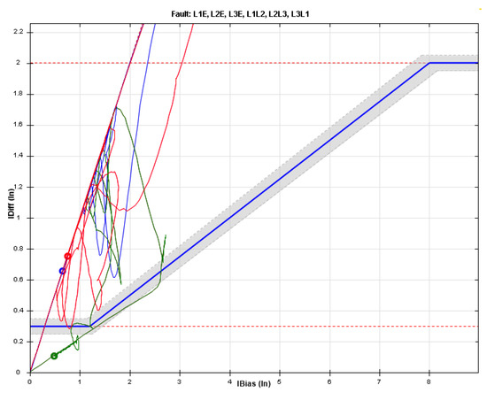
Figure 1.
Differential relay setting curve and differential trajectory mapped on it.
To generate a differential trajectory of the relay, six currents sampled (from both sides of the transformer) at different sampling times of the event must be used. Similar to what is presented in Table 1, these six currents are recorded in the COMTRADE file of the relay output.

Table 1.
An example of the COMTRADE file for a differential relay after an incident.
The six currents recorded in Table 1 (, , and ) and (, , and ) are the secondary currents of terminals CT1 and CT2 (CTs on both sides of the transformer), respectively, which are recorded at different sampling times.
It is not easy to generate a differential trajectory from stored current samples for different phases (at different times). This is due to the fact that and must be calculated at different times to generate a differential relay trajectory. However, these two parameters are on the secondary sides of CTs on both sides of the protected transformer, and their calculation requires the application of various conditions that affect the input currents of the relay.
The only exception in this regard is Siemens relays. Similar to Figure 2, these relays can record and values for different sampled moments in addition to six relay input currents in their output COMTRADE file. Therefore, SIGRA software can easily generate the differential trajectory of the relay by reading this COMTRADE file.
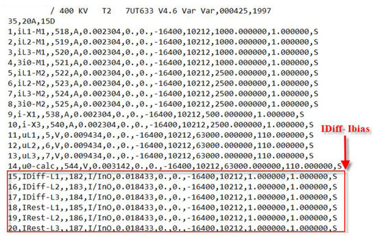
Figure 2.
A sample of a COMTRADE file recorded by a Siemens relay.
Due to the fact that the and values of other brands of differential relays are not registered in their COMTRADE files, therefore, the differential trajectory of these relays cannot be generated easily. Therefore, it is essential to develop a method that is able to create a differential trajectory for all differential protection relays.
3. Proposed Method
In general, the magnitude and phase of the relay input currents are affected by the structure of the protected transformer and the connections of the CTs on both sides [25]. As shown in Figure 3, the CTs ratio, equipping/not equipping them with a zero sequence elimination (ZSE) unit, the connection type of CTs, and connecting/not connecting the secondary side of CTs to the ground are the factors affecting current inputs. On the other hand, according to Figure 3, the transformer vector group can also affect the input currents on the differential relay. Therefore, it is necessary to consider the role of all these factors in generating the differential trajectory of the differential relay.
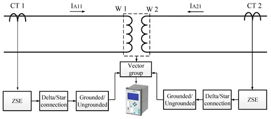
Figure 3.
Factors affecting differential relay current inputs.
To consider all the factors affecting the input currents of a differential relay and to generate a differential trajectory, Figure 4 is presented. As seen in Figure 4, the information stored in the relay can be extracted from two forms, including RIO and COMTRADE files. An RIO file is actually the standard format for reading a protective relay setting or transferring it to a relay tester or other relays. Table 2 shows the available information in an RIO file of a differential relay which consists of the relay settings, the characteristics of the protected transformer, and CT ratios [26]. This information is used in the differential trajectory generation process. Additionally, the settings of the differential relay are available in the RIO file. Therefore, the curve of the differential relay can be acquired in order to analyze the correct/incorrect operation of the differential relay.
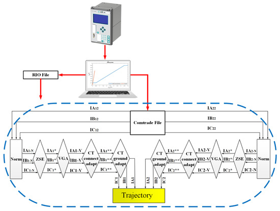
Figure 4.
Differential trajectory generation process via differential relay COMTRADE file.

Table 2.
Information stored in the RIO file of a differential relay.
According to Figure 4, six secondary side currents of CT1 (, , and ) and CT2 (, , and ) are extracted from the COMTRADE file of a differential relay. As revealed in Figure 4, based on these six currents passing through different processing units, the differential trajectory is generated in the Trajectory unit. It should be noted that the processing units shown in Figure 4 are the same factors affecting the input currents of the differential relay, which have been presented in Figure 3. Due to the fact that, depending on the CTs and transformer connections, some of these units may not operate, these units are shown conditionally in Figure 4.
3.1. Normalizing the Currents
In the first step of generating the differential trajectory, currents extracted from the relay COMTRADE file are normalized. Therefore, according to Figure 4, the “Norm” processing unit is used to normalize the currents on both sides of the transformer. In this unit, Equations (1) and (2) are used to normalize the currents of the primary and secondary sides of the transformer, respectively [25].
where , , and are the normalized currents of the CT1 secondary side and , and are the normalized currents of the CT2 secondary side for the j-th recorded samples in the COMTRADE file. Additionally, and are the nominal currents of the CT1 and CT2 primary sides, which are extracted from the RIO file according to Table 2. It should be noted that the total number of samples stored in the COMTRADE file for each of the six currents is ().
In Equations (1) and (2), and are the base currents on the primary and secondary sides of the transformer, respectively. To calculate these base values, two cases are considered.
Case one: If the CT1 and CT2 rated currents have been determined according to the transformer’s primary and secondary side rated currents, the rated currents of the transformer are used to calculate these base values. For this purpose, Equations (3) and (4) are used.
where and are the rated voltages of the primary and secondary sides of the transformer, respectively, and is the rated power of the protected transformer (VA). According to Table 2, these parameters are obtained from the relay RIO file.
Case two: In some cases, due to the replacement of CTs, the primary rated currents of the CTs are noticeably different from the rated currents of the transformer. In this case, the base current is selected based on the nominal current of CTs on both sides of the transformer and using Equations (5) and (6).
To use these equations, the value is calculated from Equation (7).
3.2. Zero Sequence Elimination
When the star-point of the transformer winding is grounded (Yn connection), the current can flow to the ground during an earth fault. This issue may cause the maloperation of the differential relay during earth faults that are outside the protection zone of the relay [27,28]. To tackle this issue, the ZSE filter is implemented in differential relays [27]. Indeed, ZSE removes the zero sequence currents flowing from the transformer side when an earth fault occurs.
In order to apply the effect of the ZSE filter on the Yn side of the transformer, the normalized currents of the previous stage are passed through the ZSE processing unit. Therefore, for differential relays that use the ZSE unit, the output currents of this unit are calculated from Equation (8) for the j-th current samples recorded on the relay COMTRADE file (, , and ) [25].
According to Figure 4, the ZSE unit is conditional on both sides of the transformer. This means that the normalized currents in each transformer side would be processed in this unit only if the transformer connection of that side is Yn. If processing is not performed in this unit, , , and on that side would be , , and .
3.3. Vector Group Adaptation
In power transformers, a winding (generally the primary winding) is selected as the reference winding for the current phase angle. The current phase angle of this winding is considered zero [25,28]. The current phase angle of the secondary winding is identified according to the transformer vector group. This means that the secondary winding current phase angle is shifted according to the transformer vector group. This phase shift can cause differential relay maloperation. For this purpose, the vector group adaptation (VGA) processor is implemented on the secondary winding [25,28]. In this unit, the phase shift is corrected using Equation (9).
where, , , and are the output currents of this unit for the j-th current samples, and is the vector group number of the transformer. For example, if the transformer vector group is Yd5, then [25]. In order to determine the coefficient, Equation (10) is used.
3.4. CT Connection Adaptation
In this unit, the output currents of the previous units are processed in a case when the transformer winding connection type differs from its CT connection type on each side of the transformer. For example, if the transformer winding is connected in star and its CT at the same side is connected in delta, this unit would process the currents. In this case, the output of this unit (, , and ) is determined by Equation (11) for the j-th current samples.
It should be mentioned that, if this unit is not used on each side of the transformer, the current outputs of this unit would be , , and at that side.
3.5. CT Grounding Adaptation
According to Figure 4, the CT grounding adaptation unit is another processing unit that conditionally analyzes the transformer’s primary and secondary side currents. As shown in Figure 5a, if the secondary side of the CT is grounded towards the transformer, the currents are not processed in this unit. Otherwise, as shown in Figure 5b, if the secondary side of the CT is grounded towards the line, the currents are shifted 180 degrees. Therefore, in this case, the output three-phase currents of this unit (, , and ) are calculated from Equation (12) for the j-th current samples.

Figure 5.
Different CTs grounding methods: (a) CTs are grounded toward the transformer; (b) CTs are grounded toward the line.
3.6. Generating a Differential Trajectory
After applying the effects of all the affecting factors on the input currents of the relay, the differential trajectory () can be generated in the Trajectory unit of Figure 4 and mapped on the relay setting curve (). For this purpose, it is necessary to calculate and for all sampled currents at different times (). Equation (13) is used to calculate [29].
where, and are the j-th samples of the Trajectory unit input currents for each phase on the primary and secondary sides of the transformer ( and ).
Contrary to , the calculation of varies for different brands of the differential relay. Therefore, Equations (14)–(16) present calculations for different relay manufacturers [30,31,32,33]. According to Table 2, the equation can be extracted from the RIO file of the differential relay.
According to the content provided, Figure 6 presents the method for generating the differential trajectory from six input currents of the transformer (). Evidently, at any time, the extracted samples from the six relay input currents () that are stored in the COMTRADE file are processed by the proposed method. Additionally, the location of the obtained sample on the setting curve is determined by calculating and for each category of registered samples. The setting curve is created via the relay settings that are extracted from the RIO file of the relay.
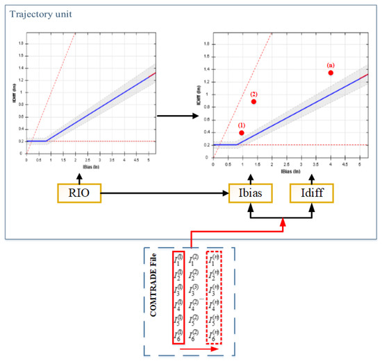
Figure 6.
Generation of the differential trajectory from current samples.
4. Simulation Results
The correct operation of differential relays in the face of faults, inrush current, and CT saturation is vital [34]. For this reason, the proposed method of this paper has been evaluated during all these cases, both in simulation studies and in an experimental setup. Figure 7 represents the general process of the evaluations that are carried out in this paper. According to this figure, different incidents (fault, inrush current, and CT saturation) are simulated in DIgSILENT software on a sample network and saved as the COMTRADE files. Simulations are performed in DIgSILENT software using EMT analysis and as instantaneous values. The simulations are performed with step sizes equal to 0.0001 s, but when creating the COMTRADE output, the sampling rate is considered to be equal to 1 kHz. These COMTRADE files are imported as the input to the proposed method, which is implemented in Matlab software, and the ability of this method to generate the differential trajectory is evaluated by the software.
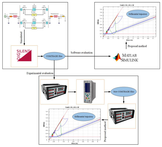
Figure 7.
Evaluations of the proposed method.
According to Figure 7, in the experimental evaluation of the proposed method, the COMTRADE files created in the previous step are applied to a differential relay through a relay tester, and the COMTRADE files of the differential relay operation during different incidents are recorded. These new COMTRADE files are imported as the input to a relay tester device in which the proposed method has already been loaded. By implementing the proposed method, the relay tester device can generate the differential trajectory from the COMTRADE records of the differential relay output.
4.1. Test System
In order to create COMTRADE files of different incidents, the sample network of Figure 8 has been implemented [34]. This network is modeled in DIgSILENT software. According to Figure 8, this network contains two 230 kV/63 kV transformers with a YNd11 vector group connection. It should be noted that transformer T2 is connected during the sympathetic inrush current analysis. As shown in Figure 8, a differential relay is implemented for T1 transformer protection. In this relay, Equation (14) with is considered to calculate . Table 3 shows the considered settings of this differential relay.

Figure 8.
Single-line diagram of the sample network for generating different incidents.

Table 3.
Information stored in the RIO file of a differential relay.
From Figure 8, it is clear that the connection of the T1 is Yn on the 230 kV side. Therefore, the ZSE unit performs processing on this side. In addition, the method of grounding CTs is toward the line (Figure 5b). Therefore, it is necessary to process currents by the CT grounding adaption unit. Another issue that should be mentioned is that the connection of CTs is considered the opposite of the T1 transformer. Therefore, it is necessary to process the currents by the CT connection adaption unit.
4.2. Experimental Setup
Figure 9 shows the experimental setup used for the experimental evaluation of the proposed method. As is clear from this figure, a Siemens 7UT6X differential relay is used to apply the incidents created in the DIgSILENT software. Considering that Figure 8 shows the location of this differential relay, therefore, the settings in this relay are the same as those presented in Table 3. As mentioned, the incidents created in DIgSILENT software are applied to the differential relay in the form of a COMTRADE file by a relay tester device in which the proposed method has already been loaded. All the currents applied in this test are the secondary currents of the CTs that are recorded in the relay’s COMTRADE file.
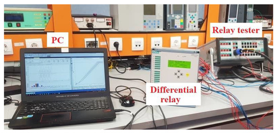
Figure 9.
Experimental setup to evaluate the proposed method.
The relay tester to implement this study has been designed and manufactured by Vebko-Amirkabir Company and has been previously reported in [20,35,36]. By connecting to a computer, this tester is able to receive COMTRADE files simulated in DIgSILENT software or generated in protective relays. Additionally, this device can inject fault currents into the differential relay through its six 32 A current sources. By using the relay’s binary inputs, it is possible to register the trip/non-trip state of the relay.
4.3. Evaluation of the Proposed Method in Different Incidents
4.3.1. Single-Phase-to-Ground Faults
In this section, the ability of the proposed method to generate a differential trajectory in the face of all types of single-phase-to-ground faults is investigated. For this purpose, in the network shown in Figure 8, a single-phase-to-ground fault is placed on the HV bus of the transformer (230 kV bus) in 0.5 s (simulations are carried out for all three types of single-phase faults). As shown in Figure 7, the recorded COMTRADE files are imported in the proposed method in MATLAB software for all types of single-phase-to-ground faults. Figure 10 shows the differential trajectory generated in MATLAB software. As seen, the proposed method has been able to generate a differential trajectory from the input COMTRADE files. It is clear from Figure 10 that the generated differential trajectory was in the relay operation zone. Consequently, the differential relay must operate for this incident. Therefore, it is concluded that the generation of a differential trajectory provides a proper understanding of the correct/incorrect operation of the differential relay.
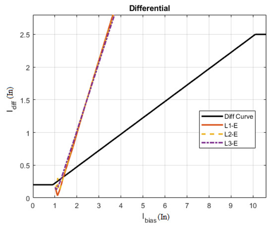
Figure 10.
The differential trajectory obtained from the COMTRADE file for single-phase-to-ground faults.
The COMTRADE files created for all types of single-phase-to-ground faults are applied to the differential relay in the experimental setup shown in Figure 9. The differential relay has recorded a COMTRADE file for each fault situation. Figure 11 shows the differential trajectory of these files generated by the relay tester using the proposed method. Comparing the results in Figure 10 and Figure 11 shows the similarity of the generated differential trajectories in the software and experimental evaluation. Therefore, the proposed method has been successful in generating the differential trajectory of all types of single-phase faults.
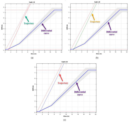
Figure 11.
The differential trajectory generated from the single-phase-to-ground faults using the relay tester: (a) L1-E; (b) L2-E; (c) L3-E.
4.3.2. Two-Phase and Three-Phase Faults
To investigate the ability of the proposed method to generate a differential trajectory for two-phase and three-phase faults, these types of faults are placed on the HV bus of the T1 transformer in Figure 8 in 0.5 s. Then, according to Figure 12, the differential trajectories of these incidents are generated for the differential relay shown in Figure 8.
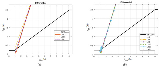
Figure 12.
The differential trajectory in the software evaluation of the proposed method: (a) two-phase faults; (b) three-phase faults.
In order to practically evaluate the proposed method for generating the differential trajectory of various phase-to-phase faults, the COMTRADE files generated by the relay tester device are applied to the differential relay. Figure 13 and Figure 14 show the differential trajectories generated using the proposed method in the relay tester for two-phase and three-phase faults, respectively. The comparison of the differential trajectories generated in these figures with the similar cases in Figure 12 clearly shows the similarity of the differential trajectories in the simulation and actual cases. Therefore, the proposed method has been successful in generating differential trajectories of various types of phase-to-phase faults.
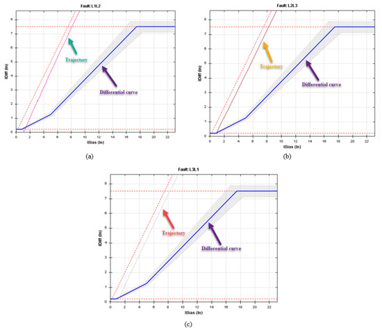
Figure 13.
The differential trajectory obtained from the two-phase fault in the relay tester: (a) L1–L2; (b) L2–L3; (c) L3–L1.
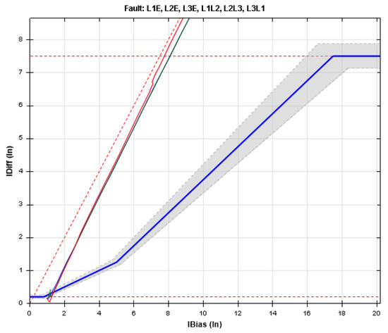
Figure 14.
The differential trajectory obtained from the three-phase fault in the relay test.
In order to check the performance when the fault occurs outside the protection zone, a three-phase fault is placed outside the protection zone (adjacent transmission line) at time 0.5. Figure 15 shows the drawn trajectory. The occurred fault has not entered into the operational area of the differential relay.
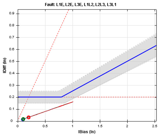
Figure 15.
The trajectory drawn from the COMTRADE file at the time of the out-of-zone fault.
In the three-winding transformer case, three sets of current inputs are used to protect the transformer. The proposed method would not face any challenge in this case. In order to prove this issue, a simulation has been performed using a three-winding transformer in the studied network. For this purpose, the T2 transformer is converted into a three-winding transformer. A three-phase fault is placed on the transformer windings at 1.2 s. Figure 16 shows the differential trajectory created by this simulation.
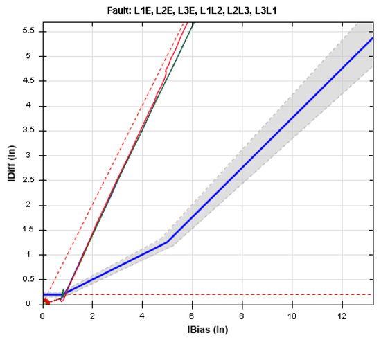
Figure 16.
The differential trajectory obtained from the COMTRADE file for a three-phase fault in a three-winding transformer.
4.3.3. Inrush Current
Inrush currents occur in power transformers during switching. These currents can cause the maloperation of a differential relay. Therefore, it is essential to evaluate the performance of differential relays during all types of inrush currents. Normal and sympathetic inrush currents are two important types of inrush currents [34]. The most important feature of the sympathetic inrush current compared to the normal inrush current is that the amplitude of the sympathetic inrush current increases over time, but the amplitude of the normal inrush current will decline over time [34].
To simulate a normal inrush current, transformer T2 is isolated from the grid. Subsequently, the power switches of transformer T1 will be closed in 20 ms to generate a normal inrush current. The sympathetic inrush current occurs in parallel transformers. To generate a sympathetic inrush current, transformer T2 is connected to the grid while the T1 transformer is connected. Figure 17 shows the differential trajectory generated by the proposed method in MATLAB software for all types of inrush currents. Clearly, the proposed method has been able to generate the differential trajectory of various types of inrush currents from COMTRADE files.
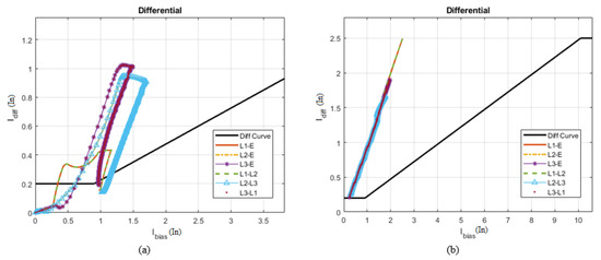
Figure 17.
Differential trajectory generated in the proposed method for inrush current: (a) normal inrush current; (b) sympathetic inrush current.
To validate the results of Figure 17, Figure 18 shows the differential trajectory generated by the proposed method for all types of inrush currents in the experimental setup. The comparison between these two figures shows that the differential trajectories generated in both the software and practical tests are identical.
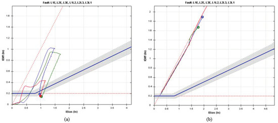
Figure 18.
Differential trajectory resulting from the inrush current test by the relay tester: (a) normal inrush current; (b) sympathetic inrush current.
4.3.4. CT Saturation
Saturation in the CT core can cause a change in the waveform of the current and, as a result, a maloperation in the protection relays. CT saturation is one of the most critical challenges that differential relays may face. For this reason, it is essential to test differential relay operation during CT saturation. In order to evaluate the proposed method for generating the differential trajectory due to CT saturation, the CT model presented in [37] has been used. Figure 19 shows the results of differential trajectory production at the time of CT saturation. As is clear, the proposed method has been successful in producing the differential trajectory of this type of transient incident.
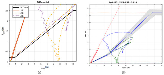
Figure 19.
Differential trajectories generated from the CT saturation test: (a) in software evaluation; (b) in experimental evaluation.
5. Comparison of the Proposed Method with Another Method
In order to further analyze the proposed method, this method has been compared with the method on SIGRA software. For this analysis, it is necessary to inject a fault current with an identified trajectory to the relay. Hence, the current tracking feature available in relay testing software can be implemented. Therefore, by adding different points on the operational axis of the differential relay, the required fault current can be created, and at the end, these generated currents can be injected into the relay. Figure 20 shows the differential trajectory created by the current tracking feature for testing the differential relay. As is clear, the start point of this trajectory is outside the operational zone of the differential relay. In the first part, the differential trajectory remains outside the operational zone of the relay. In the second part, the trajectory has entered the operational zone of the differential relay from the third slope. Finally, in the third part, the trajectory exits the operational zone of the differential relay from the second slope and returns to the starting point.
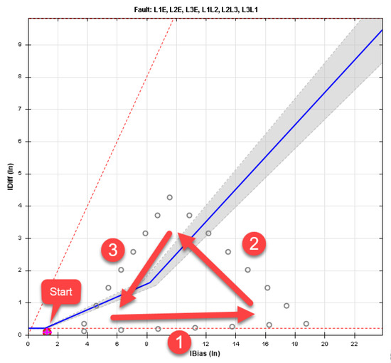
Figure 20.
Current trajectory created by the current tracking feature for testing the differential relay.
The fault currents generated using the current tracking feature of the tester are shown in Figure 21a. These fault currents are associated with currents from both sides of the protected transformer. As is clear from Figure 21b, six fault currents are entered into the relay, and this relay has operated appropriately. After applying this fault to the relay shown in Figure 9, the COMTRADE file of the relay has been extracted. The differential trajectory of this file is produced and compared by the method proposed in this paper and also by SIGRA software version 4.58 (Develop by Siemens, Munich, Germany).
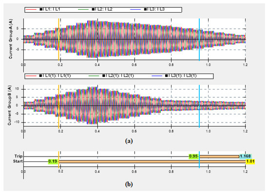
Figure 21.
Fault current generated by current tracking (according to Figure 20) and differential relay operation. (a) The fault currents generated using the current tracking feature; (b) Relay operation.
Figure 22 shows the differential trajectory produced by SIGRA software. As is clear from this figure, the starting point of the trajectory shown in Figure 20 is wrongly determined by SIGRA software. In the following, Section 1 and Section 2 (according to Figure 20) are calculated accurately. However, the trajectory has not exited the operational zone (Section 3, according to Figure 20) through the second slope, which was a mistake by SIGRA software, and it has exited the operational zone from the third slope.
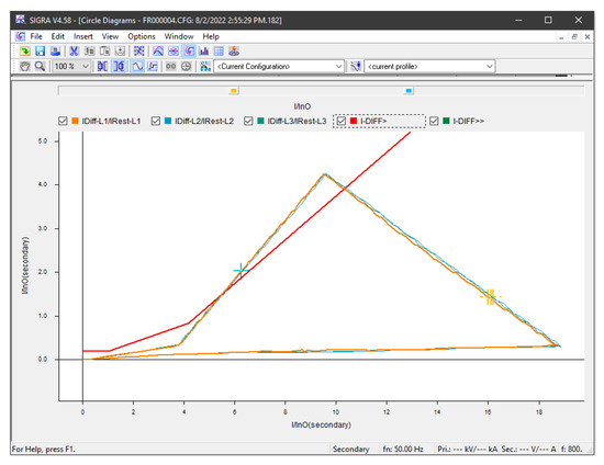
Figure 22.
The trajectory created by SIGRA software.
Figure 23 shows the trajectory generated by the proposed method in this paper. As is clear from Figure 23, the starting point of the trajectory has been calculated with high accuracy. Additionally, according to the figure, the trajectory of Section 1, Section 2 and Section 3 (according to Figure 20) is correctly generated, and in Section 3, it has exited the operation zone of the relay from the second slope.
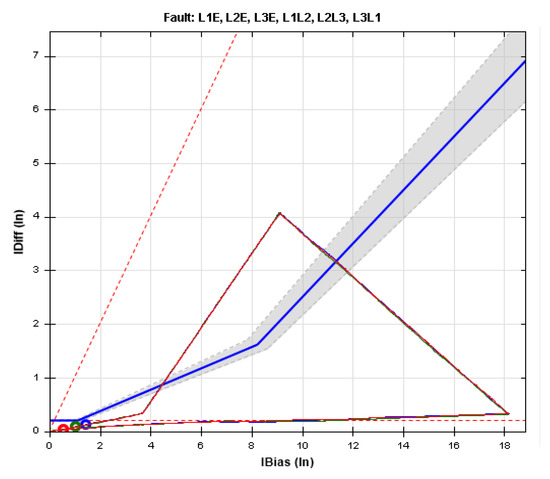
Figure 23.
The trajectory created by the proposed method.
6. Conclusions
Despite the many advantages of the differential relay in protecting power transformers, it may be vulnerable to various transient phenomena and cause its maloperation. Although various studies are in the field of performance improvement and differential relay testing, it is still not possible to evaluate the correct/incorrect operation of the differential relay after its operation. This problem requires analyzing the behavior of six input currents of the differential relay at different sampling times, considering the relay setting curve. Hence, a method for generating a differential trajectory from the six currents extracted from the COMTRADE file of the differential relay and mapping them on the setting curve of this relay was presented in this paper. In the proposed method, all the influencing factors on the six currents recorded in the COMTRADE file of the differential relay, including the effects of the CTs connections type and the protected transformer connections type, were considered. The proposed method was evaluated during different incidents (faults, inrush current, and CT saturation) in the simulation and experimental tests. In the experimental tests, the COMTRADE files of simulated incidents were applied to a differential relay through a tester device. Then, the output COMTRADE files of the relay were evaluated by the relay tester in which the proposed method was loaded. The presented results show that the proposed method, using the output COMTRADE files of the relays, is able to generate the differential trajectory of the different incidents in which differential relays may encounter. Therefore, by implementing this method, it is possible to evaluate the correct/incorrect operation of the differential relay for any incident.
7. Future Research
The method presented in this paper is effective only for microprocessor differential relays that are able to record the COMTRADE file. However, because the old electromechanical and electrostatic relays cannot record the COMTRADE file, in future research, the authors intend to build hardware that can create and record COMTRADE files for all differential relays. The COMTRADE file will be saved by this hardware according to the IEEE C37.111 standard.
Author Contributions
Conceptualization, S.A.H. and A.A.N.; methodology, B.T.; software, A.A.N. and F.R.; validation, S.A.H., A.A.N. and B.T.; formal analysis, F.R. and H.H.-D.; investigation, S.A.H.; resources, A.A.N.; data curation, B.T.; writing—original draft preparation, S.A.H. and B.T.; writing—review and editing, H.H.-D.; visualization, S.A.H.; supervision, F.R.; project administration, F.R. All authors have read and agreed to the published version of the manuscript.
Funding
This research received no external funding.
Data Availability Statement
Data sharing not applicable to this article as no datasets were generated or analysed during the current study.
Conflicts of Interest
The authors certify that they have no affiliations with or involvement in any organization or entity with any financial interest (such as honoraria; educational grants; participation in speakers’ bureaus; membership, employment, consultancies, stock ownership, or other equity interest; and expert testimony or patent-licensing arrangements), or non-financial interest (such as personal or professional relationships, affiliations, knowledge or beliefs) in the subject matter or materials discussed in this manuscript.
References
- Rexhepi, V. An Analysis of Power Transformer Outages and Reliability Monitoring. Energy Procedia 2017, 141, 418–422. [Google Scholar] [CrossRef]
- Rahmati, A.; Sanaye-Pasand, M. Protection of power transformer using multi criteria decision-making. Int. J. Electr. Power Energy Syst. 2015, 68, 294–303. [Google Scholar] [CrossRef]
- Hosseini, S.M.; Mazlumi, K. A new hybrid method based on discrete wavelet transform and cross-correlation function to discriminate internal faults from inrush currents. Arab. J. Sci. Eng. 2014, 39, 7159–7172. [Google Scholar] [CrossRef]
- Taheri, A.A.; Abdali, A.; Taghilou, M.; Alhelou, H.H.; Mazlumi, K. Investigation of mineral oil-based nanofluids effect on oil temperature reduction and loading capacity increment of distribution transformers. Energy Rep. 2021, 7, 4325–4334. [Google Scholar] [CrossRef]
- Rangel, A. Electromechanical Differential Relays Misoperation and Investigation. In Proceedings of the 2021 74th Conference for Protective Relay Engineers (CPRE), Virtual, 22–25 March 2021; pp. 1–5. [Google Scholar]
- Ali, E.; Helal, A.; Desouki, H.; Shebl, K.; Abdelkader, S.; Malik, O.P. Power transformer differential protection using current and voltage ratios. Electr. Power Syst. Res. 2018, 154, 140–150. [Google Scholar] [CrossRef]
- Barakat, M.A.; Hatata, A.Y.; Badran, E.A. Protection of transformer due to external fault between two voltage levels using overvoltage protection and sequence component of currents. Electr. Power Syst. Res. 2020, 184, 106339. [Google Scholar] [CrossRef]
- Saleh, S.A.; Rahman, M.A. Real-time testing of a WPT-based protection algorithm for three-phase power transformers. IEEE Trans. Ind. Appl. 2005, 41, 1125–1132. [Google Scholar] [CrossRef]
- Taheri, B.; Hosseini, S.A.; Salehimehr, S. An Energy Variation-Based Method for Discrimination Between the Internal Fault and Inrush Current in Power Transformers. In Proceedings of the 2020 14th International Conference on Protection and Automation of Power Systems (IPAPS), Tehran, Iran, 31 December 2019–1 January 2020; pp. 47–53. [Google Scholar]
- Bainy, R.G.; Silva, K.M. Enhanced Generalized Alpha Plane for Numerical Differential Protection Applications. IEEE Trans. Power Deliv. 2021, 36, 587–597. [Google Scholar] [CrossRef]
- Bejmert, D.; Kereit, M.; Mieske, F.; Rebizant, W.; Solak, K.; Wiszniewski, A. Power transformer differential protection with integral approach. Int. J. Electr. Power Energy Syst. 2020, 118, 105859. [Google Scholar] [CrossRef]
- Kumar, S.; Kumar, D. An Efficient Hybrid Approach For Performance Analysis of Transformer Protected. In Proceedings of the 2018 3rd IEEE International Conference on Recent Trends in Electronics, Information & Communication Technology (RTEICT), Bangalore, India, 18–19 May 2018; pp. 754–758. [Google Scholar]
- Moravej, Z.; Bagheri, S. Testing of differential relay operation for power transformers protection using RTDS. In Proceedings of the 2015 30th International Power System Conference (PSC), Tehran, Iran, 23–25 November 2015; pp. 99–105. [Google Scholar]
- He, R.; Peng, H.; Jiang, Q.; Zhou, L.; Zhu, J. Performance Analysis and Threshold Quantization of Transformer Differential Protection Under Sampled Value Packets Loss/Delay. IEEE Access 2019, 7, 55698–55706. [Google Scholar] [CrossRef]
- Beaumont, P.; Kawano, F.; Kawarada, A.; Kase, T.; Sugiura, H.; Lam, F.; Hurd, J.; Worthington, P.; Richards, D.; Merriman, P. Performance evaluation of current differential relays over a wide area network. In Proceedings of the 11th IET International Conference on Developments in Power Systems Protection (DPSP 2012), Birmingham, UK, 23–26 April 2012; pp. 1–6. [Google Scholar]
- Azeem, A.; Jamil, M.; Qamar, S.; Malik, H.; Thokar, R.A. Design of Hardware Setup Based on IEC 61850 Communication Protocol for Detection & Blocking of Harmonics in Power Transformer. Energies 2021, 14, 8284. [Google Scholar]
- Ehsan, U.; Jawad, M.; Javed, U.; Shabih Zaidi, K.; Ur Rehman, A.; Rassõlkin, A.; Althobaiti, M.M.; Hamam, H.; Shafiq, M. A Detailed Testing Procedure of Numerical Differential Protection Relay for EHV Auto Transformer. Energies 2021, 14, 8447. [Google Scholar] [CrossRef]
- Turner, S. Testing numerical transformer differential relays. In Proceedings of the IEEE/IAS Pulp & Paper Industry Technical Paper Conference, Fort Collins, CO, USA, 26–29 April 2009; pp. 106–111. [Google Scholar]
- IEEE Std C37.111-1991; IEEE Standard Common Format for Transient Data Exchange (COMTRADE) for Power Systems. IEEE: Piscataway, NJ, USA, 1991; pp. 1–28. [CrossRef]
- Hosseini, S.A.; Sadeghi, S.H.H.; Nasiri, A. Decentralized Adaptive Protection Coordination Based on Agents Social Activities for Microgrids With Topological and Operational Uncertainties. IEEE Trans. Ind. Appl. 2021, 57, 702–713. [Google Scholar] [CrossRef]
- Salehimehr, S.; Taheri, B.; Hosseini, S.A.; Askarian Abyaneh, H.; Razavi, F. A New Power Swing Detection Method Based on Hilbert Transform. Int. J. Ind. Electron. Control Optim. 2020, 3, 103–114. [Google Scholar] [CrossRef]
- Wu, L.; Liu, C.; Chien, S.; Chen, C. The Effect of Inrush Current on Transformer Protection. In Proceedings of the 2006 38th North American Power Symposium, Carbondale, IL, USA, 17–19 September 2006; pp. 449–456. [Google Scholar]
- Turner, S. Using COMTRADE records to commission protection. In Proceedings of the PES T&D 2012, Orlando, FL, USA, 7–10 May 2012; pp. 1–8. [Google Scholar]
- Turner, S. Using COMTRADE records to test protective relays. In Proceedings of the 2012 65th Annual Conference for Protective Relay Engineers, College Station, TX, USA, 2–5 April 2012; pp. 401–409. [Google Scholar]
- Ziegler, G. Numerical Differential Protection: Principles and Applications, 2nd ed.; Siemens, A., Ed.; Publicis Publishing: Erlangen, Germany, 2012; p. 287. [Google Scholar]
- Ali, M.A. Hybrid technique for testing IEC 61850 based IEDs of distance protection. In Proceedings of the 2017 Nineteenth International Middle East Power Systems Conference (MEPCON), Cairo, Egypt, 19–21 December 2017; pp. 353–358. [Google Scholar]
- Zheng, T.; Yang, X.; Guo, X.; Wang, X.; Zhang, C. Zero-Sequence Differential Current Protection Scheme for Converter Transformer Based on Waveform Correlation Analysis. Energies 2020, 13, 1814. [Google Scholar] [CrossRef]
- Siemens. Differential Protection 7UT6 User Manual, 2003; Volume 4.
- Taheri, B.; Sedighizadeh, M. A moving window average method for internal fault detection of power transformers. Clean. Eng. Technol. 2021, 4, 100195. [Google Scholar] [CrossRef]
- Siemens. SIPROTEC Differential Protection 7UT612 (V4.0). Manual, pp. 1–360. Available online: https://www.siemens.com/download?DLA06_1288 (accessed on 8 September 2022).
- Schneider-Electric. Easergy MiCOM P64× (P642, P643 & P645) Transformer Protection Relay User Manual. 2022; pp. 1–1240. Available online: https://www.se.com/ww/en/download/document/P64x_EN_M_A62__04X_JK/ (accessed on 8 September 2022).
- G.E.M., Inc. 745 Transformer Protection System User Manual; 2011; pp. 1–314. [Google Scholar]
- ZIV. Instructions Manual for IDV Models (IDV Transformer Differential Protection and Control IED), 2020.
- Nazari, A.A.; Razavi, F.; Fakharian, A. A novel method to differentiate internal faults and inrush current in power transformers using adaptive sampling and Hilbert transform. Iran. Electr. Ind. J. Qual. Product. 2022, 11, 97–110. [Google Scholar]
- Taheri, B.; Hosseini, S.A.; Askarian-Abyaneh, H.; Razavi, F. Power swing detection and blocking of the third zone of distance relays by the combined use of empirical-mode decomposition and Hilbert transform. IET Gener. Transm. Amp Distrib. 2020, 14, 1062–1076. [Google Scholar] [CrossRef]
- Taheri, B.; Hosseini, S.A.; Salehimehr, S.; Razavi, F. A New Method for the End-To-End Testing of Differential Relays. In Proceedings of the 2020 14th International Conference on Protection and Automation of Power Systems (IPAPS), Tehran, Iran, 31 December 2019–1 January 2020; pp. 110–118. [Google Scholar]
- Tziouvaras, D.A.; McLaren, P.; Alexander, G.; Dawson, D.; Esztergalyos, J.; Fromen, C.; Glinkowski, M.; Hasenwinkle, I.; Kezunovic, M.; Kojovic, L. Mathematical models for current, voltage, and coupling capacitor voltage transformers. IEEE Trans. Power Deliv. 2000, 15, 62–72. [Google Scholar] [CrossRef]
Publisher’s Note: MDPI stays neutral with regard to jurisdictional claims in published maps and institutional affiliations. |
© 2022 by the authors. Licensee MDPI, Basel, Switzerland. This article is an open access article distributed under the terms and conditions of the Creative Commons Attribution (CC BY) license (https://creativecommons.org/licenses/by/4.0/).