Article

Study on Blasting Effect Optimization to Promote Sustainable Mining under Frozen Conditions

1
School of Management, Xi’an University of Architecture and Technology, Xi’an 710055, China
2
Kunming Prospecting Design Institute, China Nonferrous Metals Industry Co., Ltd., Kunming 650051, China
*
Author to whom correspondence should be addressed.
Sustainability 2022, 14(24), 16479; https://doi.org/10.3390/su142416479
Submission received: 6 November 2022 / Revised: 6 December 2022 / Accepted: 7 December 2022 / Published: 9 December 2022

Abstract

:
In order to respond to the theme of national green and healthy sustainable development and in response to the problems of large block rates and pollution of the environment after the blast mining of underground rocks in alpine areas, we conducted research on the joints of underground rocks and the blastability of frozen rocks. According to the actual geological conditions of an underground mine blasting in Heilongjiang Province, three kinds of joint blasting geometric models were established. The rock mass blasting process of different types of joints was simulated by LS-DYNA software and the influence law of joints on rock mass blasting was summarized. The blasting crater test and the triaxial compression test of frozen rock were carried out. Combined with the blasting fragmentation characterization function (R-R and G-G-S), the blasting fragmentation, strength and stiffness of frozen rock at different temperatures were obtained. Based on the above, the blasting parameters of a multi-joint underground rock mass in an alpine region were optimized: hole spacing 4.0 m, row spacing 2.5 m, hole depth 11.5 m, V-type initiation network. The optimized blasting parameters significantly improved the mining efficiency and reduced the large lump rate to 3.1%. In order to promote the sustainable exploitation of resources in alpine regions, this study optimized the blasting technology of underground rock mass.

1. Introduction

China’s alpine regions are mainly divided into the Qinghai-Tibet Plateau [1] and Northeast China in the middle and low latitudes. These areas are rich in mineral resources and lie beneath frozen rock. With the rapid development of China’s economy, the demand for mineral resources is increasing. People need to mine mineral resources in alpine areas [2]. However, the disorderly development of mineral resources will destroy the fragile ecological environment of the local area. It is very difficult for the damaged natural environment to repair itself [3], which brings great difficulties to subsequent sustainable mining activities. Therefore, it is necessary to study the influence of frozen rock properties on underground blast mining in cold regions [4]. Different frozen rock temperatures are between 0 °C and −10 °C and their physical and mechanical properties vary greatly. The physical and mechanical properties of frozen rock, including explosiveness and drillability, need to be considered in the mining and blasting of frozen rock. The existence of joints in underground frozen rock in alpine regions also makes the interaction between explosives and rock extremely complex, changes the failure mode of rock and has a great impact on the blasting effect [5,6,7]. In a word, the multi-joint and high-freezing properties of underground frozen rock bring many difficulties to blast mining. The blasting of underground frozen rock destroys the local vegetation. The destroyed vegetation is not only difficult to restore [8], but also causes creeping landslides in the permafrost layer. This poses a great danger to the local ecological environment [9]. Therefore, this paper studies the blasting properties of underground jointed frozen rock in alpine regions. The blasting parameters of underground frozen rock in alpine regions are optimized [10] to reduce the harm of blasting damage to the ecological environment and to promote the sustainable exploitation of underground minerals in alpine regions.
The survey found domestic and foreign scholars in the field of alpine environments and jointed rock blasting research in the following areas. Zhao established a one-dimensional analysis model of jointed rock mass and carried out dimensional analysis to explore the influence of joint characteristics on the propagation law of stress waves. They found that there is a negative correlation between the development degree of joints in the blasting area and the blasting effect [11]. Gnirk’s experiments showed that the influence of structural surfaces such as joints on blasting effectiveness exceeded the influence of other physical and mechanical properties of the rock mass [12]. Zhu studied and predicted the characteristics of block size distribution after blasting in nodular development areas [13]. Xu, Li and Zhong studied the blasting scheme of nodular rock masses [14,15,16]. Zhao and others combined the geological conditions, environmental factors and implementation effects of a blasting operation in Yulong Copper Mine in the alpine region of Tibet. They optimized the blasting parameters from the aspects of hole spacing, row spacing and charging structure [17]. Song Jiang et al. combined a GBRT algorithm and extreme learning machine to establish a rock slope risk prediction model. They used the model to predict the landslide risk and displacement risk of jointed rock slope [18,19]. Li et al. analyzed the evolution characteristics of nodular fissures on overlying rock layers [20]. In summary, long-term research has been carried out at home and abroad on the blasting engineering technology of frozen rock for many years. However, researchers have mainly studied the basic physical and mechanical properties of frozen rock and the factors closely related to the project, as well as the engineering problems such as frost heave, thaw settlement, slope and subgrade instability in engineering applications. There is little in the literature on the blastability and blasting technology of frozen rock. There is no systematic study on the blastability of mines with developed joint fissures and multiple occurrence geological structures and alpine environmental conditions. However, with China’s green, healthy and sustainable mining requirements and the further development of the western development, it is of great strategic significance to solve this problem [21,22,23].
On the basis of previous studies, this paper focuses on the influence and restriction of mine joint fissure and temperature on blasting. Based on the temperature change, the blasting property of frozen rock is studied. The influence of rock mass with different temperatures and joint fissures on the propagation of blasting stress waves and the law of their mechanical properties are studied. Taking an underground mine in Heilongjiang as the background, the blasting situation on site was investigated and the existing problems and their causes were analyzed. The blastability of underground rock mass in mines was studied by dynamic experiments, software simulation analysis and field tests in the field of blasting research. This paper also designed the blasting parameters of underground rock mass under multi-joint and high-freezing conditions, so that the blasting effect was significantly improved. This study can provide reference for the sustainable mining of underground minerals in alpine regions.

2. Joint Blasting Model

2.1. Joint Blasting Geometric Model

The effect of joints on the blasting effect is mainly in two aspects. Firstly, the stress waves are reflected at the joint surface. The stress waves are transformed from incident compressive stress waves to reflected tensile waves, forming a reflected tensile crack zone between the joint and the hole. Secondly, the stress waves form a wing crack zone at the end of the joint, which is similar to the diffraction effect of waves. Based on the above, this study classifies the joints into three types according to their length and their relative position to the borehole. Firstly, when the length of the joint is much larger than the diameter of the borehole and no wing cracks appear at both ends of the joint during blasting, the joint is an infinitely long joint. Secondly, when the length of the joint is much larger than the diameter of the borehole and wing cracks appear at one end of the joint during blasting but not at the other end, the joint is a semi-infinite joint. Thirdly, when the length of the joint is of the same order of magnitude as the diameter of the borehole and wing cracks appear at both ends, the joint is a semi-infinite joint. The length of the joint is of the same order of magnitude as the diameter of the hole. The joint with wing cracks at both ends is a short joint.
The ANSYS/LS-DYNA(LS-DYNA) program has a wide variety of contact types. It uses a rich and advanced material model and has a powerful large model analysis capability. It can effectively analyze nonlinear impact dynamics’ problems. It can simulate the explosion process in various media and various types of engineering blasting processes. In this study, a rectangular area containing a vertical pillar of joints was taken as the object of study and three geometric models of joint blasting were established (see Figure 1). The model size was 60 d × 60 d and the diameter of the blast hole was d = 5 mm, which was located at the center of the rock. One joint with a width of 0.1 d and parallel to the right-side boundary was set at R from the center of the blast hole. The left side and bottom side of the model were constrained by displacement. The static stress σ0 was applied to the right side of the vertical joint surface. Reflection-free boundary conditions were applied around the model boundary to eliminate the influence of reflected waves on the dynamic response of the structure at the artificial boundary. The rock medium in the model adopted an unequal grid. The closer the distance to the grain was, the denser the grid. The farther the distance to the grain was, the sparser the grid.

2.2. Explosives Equation of State and Rock Material Parameters

In this paper, the LS-DYNA program was selected to simulate the blasting process of Trinitrotoluene (TNT) [24] explosive in granite. TNT explosive was simulated by explosive unit (* MAT_HIGH_EXPLOSIVE_BURN) and its related state equation (* EOS_JWL) was defined. The explosive material parameters are shown in Table 1. The state equations are shown in Equations (1)–(3): the equation of state is:
P = F · peos
F = {   2 ( t     t 1 ) D   ·   A e m a x 3 v e , t > t 1 0   ,   t   t 1    
P e o s = A ( 1     ω R 1 V ) e R 1 V + B ( 1     ω R 2 V ) e R 2 V   +   ω ρ
where P is the explosion pressure; F is the rate of release of chemical energy of the explosive; D is the explosive burst speed; Aemax and Ve are the maximum cross-sectional area and volume of the explosive, respectively; t, t1 are the current time and the detonation time of a point within the explosive, respectively; Peos (1) is the detonation pressure; V is the relative volume; Peos (2) is the gas pressure of the burst products; A, B, R1, R2 and ω are material constants, obtained by experimental fitting; ρ is the density; e is the internal energy [25].
In this paper, the quality of the granite rock masses was evaluated on the basis of field sampling. The indoor physical and mechanical tests of the rock samples were carried out in accordance with the provisions of the “Rock Test Methods Standard” of the People’s Republic of China. The rock mass material model adopted the bilinear kinematic hardening model; the key field was (* MAT_PLASTIC_KINEMATIC). The calculation considered failure, and the yield stress σY was related to the strain rate ε ˙ of the rock mass (Equation (4)) [26]. The material model parameters at different temperatures are shown in Table 2.
σ Y = [ 1 + ( ε ˙ C ) 1 P ] ( σ Y 0 + β E P ε P e f f   )
  E P = E 0 E t a n E 0     E t a n
where σY0 is the initial yield stress; ε is the strain rate; C and P are Cowper–Symonds strain rate parameters, for granite take C = 2.5 m−1 and P = 4.0; β is the hardening parameter 0 ≤ β ≤ 1; EP is the modulus of elasticity; Etan is the tangential modulus; ε P e f f is the effective plastic strain of the rock mass, given by Equation (6).
  ε P e f f = 0 t P d ε p e f f
where tP is the cumulative time of occurrence of plastic strain.
For joint materials, the joint was assumed to be an elastoplastic body. The material model was selected as (* MAT_PLASTIC_KINEMATIC). The material parameters are shown in Table 3.
For ice structures in rock masses, the material model is No. 14 in the LS-DYNA material library (* MAT_ISOTROPIC_ELASTIC_FAILURE). The material model parameters are shown in Table 4 below:
The (* MAT_NULL) model can be used for air, which is suitable for gas or fluid materials. The material model allows the state equation to ignore the influence of deviatoric stress in the calculation process. The main parameters of the air are shown in Table 5.

2.3. Numerical Simulation Results and Analysis

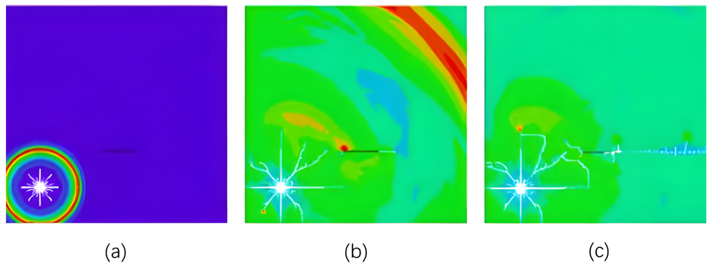
2.3.1. Analysis of Reflections and End Effects at the Nodal Surface of Semi-Infinite Joints

In this study, LS-DYNA software was used to simulate the blasting process of jointed granite under different static stresses. The influence of joint length and relative position and initial stress in the rock mass on the blasting effect was analyzed. This paper selects the relay thickness of 0.1 d (remaining unchanged) joint filling medium for soft rock. The joints were filled with media without damage. The node theoretical model used in the simulation program was the joint blasting geometric model in 2.1 above. Based on this model, the blasting process under different joint lengths was simulated. In order to show the characteristics of blasting crack propagation more clearly, this paper used the type of 2D modeling.
The first study was to investigate the characteristics of semi-infinite joint end-derived wing crack expansion and the reflected tensile damage effect inside under the explosive blast stress. Figure 2 shows the reflected tensile damage condition and end-derived wing crack expansion of the joint surface for three working conditions: no filling of the joint at R = 5 d, filling and filling of the joint at R = 20 d.
Result analysis shows that, regardless of whether the joints were filled or not, reflective tensile cracks with parallel interfaces appeared at the joints. These cracks interacted with the radial radiating cracks generated by the explosion to form a crack-intensive damage zone between the gun hole and the joints. Due to the geometric asymmetry of the joints and the reflected tensile effect, the crack area had a tendency to expand outward from the end of the joints along the joints.

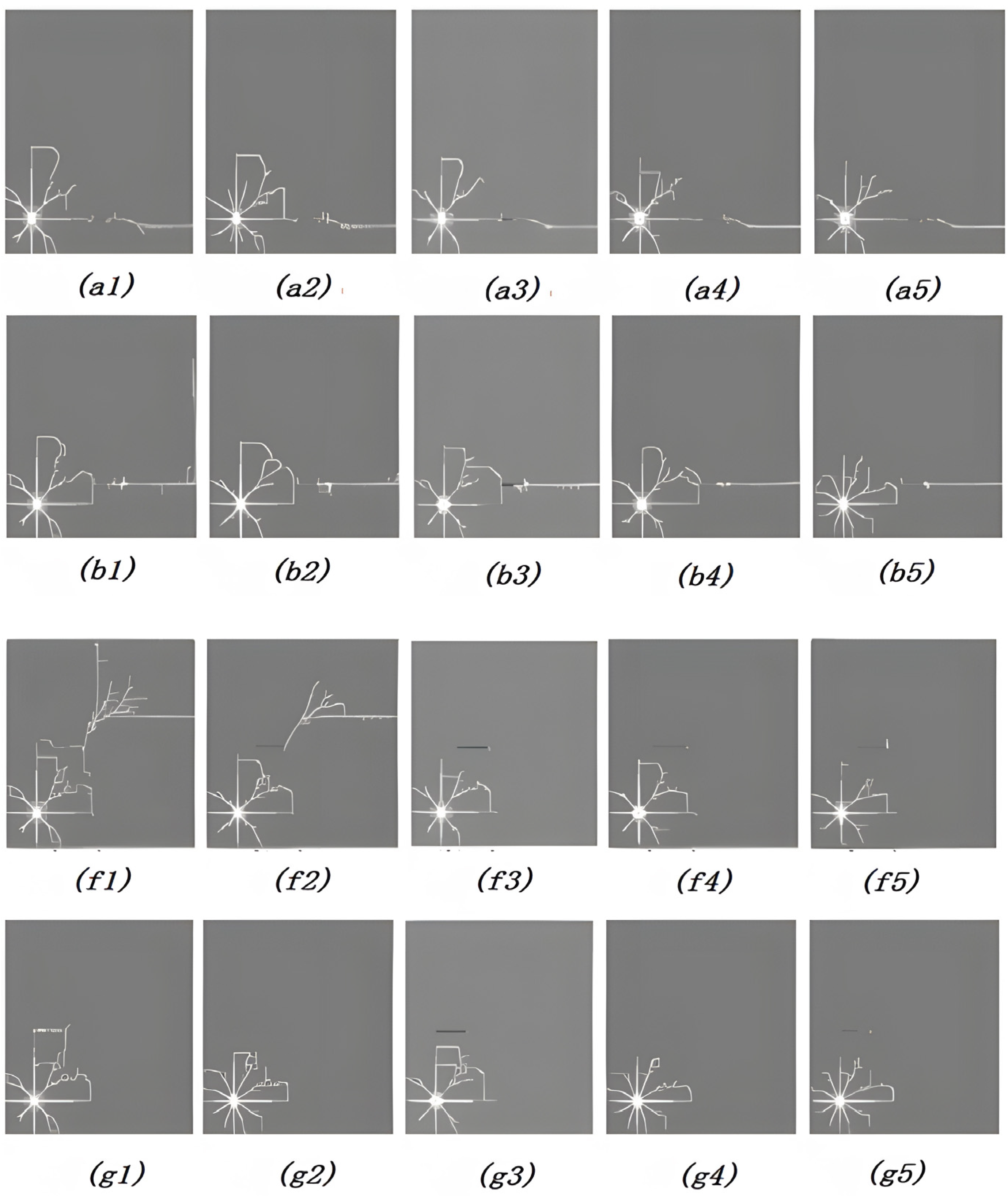
2.3.2. Analysis of the Effect of Nodal and Gun Hole Spacing on Blast Crack Expansion

In order to study the effects of nodal location and static stress on the blasting effect, the blasting crack expansion process of granite containing a long nodal crack was simulated for several cases with R/d of 5, 10, 15, 20, 25 and σ0 of 0, 5, 10, 20, 30, 40 MPa, respectively. Figure 3 shows the blasting crack expansion process of the rock with R = 10 d. The vertical line in the middle of the model is the vertical long joint in the simulated long-jointed rock mass. Figure 4 shows the crack formation in the rock after the completion of blasting with different R.
It can be seen from the diagram that, after the explosion of the explosive, the explosion stress wave propagated uniformly around. When the stress wave met the joint, the incident stress wave was divided into a reflected tensile wave and a transmitted compressive stress wave. The stress value was discontinuous at the joint surface. The reflected tensile stress wave caused cracks in the rock mass inside the joint and expanded in the direction of the blast hole. The tensile cracks and the radial cracks intersected and penetrated, forming a crack-intensive area near the inside of the joint. The results show that only a small number of blasting main cracks penetrated the joint in a small distance and the extension length was very small. As the distance increased, the joint completely blocked the expansion of the main blasting crack. The damage degree of the reflected tensile stress wave generated by the joint surface to the rock between the blasting source and the joint was significantly enhanced, which improved the blasting effect in this area.

2.3.3. Analysis of the Effect of Static Stress on Blast Crack Expansion

Figure 5 shows the change of the reflective tensile zone with the static stress at R/d = 15. It can be seen from the diagram that, with the increase in static stress, the shape of the reflective tensile failure zone did not change significantly. The size perpendicular to the static load direction was slightly reduced. Although the area of the reflective tensile failure zone decreased, the limit distance Ru did not decrease with the increase in stress.

2.3.4. Analysis of Crack Expansion Characteristics of the Nodal End-Derived Wing

Figure 6 and Figure 7 simulate the blasting process for 35 conditions with stress σ0 of 0, 10, 20, 30 and 40 MPa and incidence angles α of 0°, 15°, 30°, 45°, 60°, 75° and 90°, respectively. The simulated rock mass was a frozen rock mass containing joint fissures under low-temperature conditions. There were ice blocks in the cracks in the rock mass. The effect of joint fissures on blasting in frozen rock mass was studied by blasting crack propagation. Among them, the distance between the blast hole and the proximal end of the joint was R = 15 d.
Figure 6 shows that when the stress wave propagation encountered the short joints, stress concentrations appeared at the two ends of the joints. This changed the stress distribution within the rock at the proximal ends of the gun holes and joints. Wing cracks were first generated at the distal end of the joints and expanded outward. The proximal winged fractures appeared a little later. They appeared and expanded toward the gun hole and intersect and penetrated with radial radiating cracks, thus forming a new fracture distribution network.
Figure 7 shows that the area of the radial crack zone produced by blasting became progressively smaller as the static stress increased from 0 to 40 MPa for the same incidence angle. The increase in the number and density of radial cracks indicates that the increase in static stress caused the blasting energy consumption to be more concentrated in a smaller area around the shell hole. This allowed the rock in this area to be more fully fragmented. In addition, the reduced blasting volume reduced the damage to the surrounding rock. The effect of static stress on the generation and expansion of node-derived wing cracks was more complex and closely related to the incidence angle. When the incident angle was small (α = 0~15°), the static pressure stress had no obvious effect on the propagation of the near line crack formed by the coalescence of radial crack, joint and wing crack, and the direction of maximum principal stress was the dominant direction of blasting crack propagation. Therefore, when the incident angle was small, the static stress had a promoting effect on the joint-derived wing crack.
In summary, this study can draw these conclusions: It can be obtained that the influence of joint fissure on the blasting effect exceeds the physical and mechanical properties of the rock mass itself. The joint fissure splits the rock mass into different sizes of natural rock, which affects the fragmentation distribution after blasting. The control of blasting fragmentation becomes difficult to achieve with the increase in joint fracture development. Therefore, in the case of high static stress, it is necessary to increase the unit consumption of explosives and to reduce the hole network parameters in order to achieve the expected rock-breaking effect.

3. Frozen Rock Blastability Study

3.1. Blast Funnel Experiment

Frozen rock has the physical and mechanical properties of interface effects between soil, rock and ice. The interface between soil and ice and rock and ice can directly affect the propagation of blast shock waves and stress waves in rock and soil and can affect the generation and development of fissures in frozen rock, thus affecting the blasting effect [27]. Livingston’s blasting funnel theory suggests that the factors reflecting the blastability of permafrost are deformation energy coefficient, optimum unit explosive consumption and block size distribution. It divides the burial depth into critical depth LC and optimum depth L0. According to Livingston’s blasting funnel theory there are:
  Δ 0   ·   E b   ·   q 1 3 = 1
where Δ0 is the optimum depth ratio, Δ 0 = L 0 L c ; Eb is the deformation energy coefficient; q is the unit explosive consumption.
For granite frozen rock, the best depth ratio L0/LC is constant. Its deformation energy coefficient is inversely proportional to the optimal unit explosive consumption. The larger the deformation energy coefficient, the smaller the unit explosive consumption, indicating that frozen rock is explosive, conversely difficult to explode.
The blasting funnel tests of granite frozen rock at different temperatures were conducted. The frozen rock specimens were removed at −10 °C and −20 °C at the specified temperature. After blasting the residue inside the funnel, it was cleaned and the funnel volume was waterproofed with plastic film. The funnel radius and funnel depth were measured several times by rotating 90° with a ruler. The blasting fragmentation was screened by stone sample sieve. The diameter of the sieve hole was 40 mm-25 mm-10 mm-0 mm. Four grades were weighed, respectively. Table 6 shows the funnel parameters for the best depth of the test.
Blasting funnel tests on frozen rock at different temperatures showed that the blasting funnel formation of frozen rock was relatively regular. The critical depth and maximum funnel volume of frozen rock decreased with the decrease in temperature. The deformation energy coefficient decreased with the decrease in temperature. Unit explosive consumption increased with the decrease in temperature. The explosiveness of frozen rock was difficult to explode with the decrease in temperature.

3.2. Frozen Rock Blasting Block Size Distribution Characteristics

Blasting fragmentation is an important index for evaluating the blasting effect. Explosive blasting releases energy and transfers it to frozen rock. The frozen rock absorbs energy and causes deformation and failure of frozen rock. Due to the different energy consumed by different damage, the distribution of blasting fragmentation can reflect the absorption of explosive blasting energy by frozen rock. Therefore, the distribution of frozen rock fragmentation reflects the explosiveness of frozen rock. In this study, the Rosin–Rammler (R-R) distribution function (Equation (8)) and the Gates–Gaudin–Schumann (G-G-S) distribution function (Equation (10)) were used to describe the distribution of the blast fragmentation bulkiness of frozen rocks [28].
Y = 100 × { 1 e x p [ ( D D 0 ) n ] } , %
where D is the fragment size; D0 is the fragment distribution parameter, the value of which is equal to the size of the fragment when the cumulative percentage under the screen is (1 − 1/e)%, about 63.2%; n is the debris distribution parameter.
n = l n ( l n 2 ) l n ( D 50 D 0 )
D50 is the average value of the fractional distribution, the size of the fractions with a cumulative percentage of 50% under the screen.
  Y = 100 ( D D m ) a , %  
where Dm is the fragment distribution parameter, its value is equal to the size of the fragment when the cumulative percentage under the screen is 100%, that is, the maximum size; a is the distribution parameter.
To find the specific distribution function, the linear regression method was used to find the distribution parameters D0, D, n, a, and the results of the regression analysis are shown in Table 7 and Table 8.
The two distribution parameters D0 and n in the distribution function represent some laws of rock fragmentation distribution. It can be seen from the table that whether it is the R-R distribution function or the G-G-S distribution function, D0 is large and D50 is also large, indicating that the average block size is large. The value of a characterizes the uniformity of the fragmentation distribution. The smaller the value of a, the higher the bulk rate of the fragments. The blasting fragmentation distribution of frozen rock obeys the G-G-S distribution function better, which can be used to predict the blasting fragmentation distribution of frozen rock under different blasting parameters.

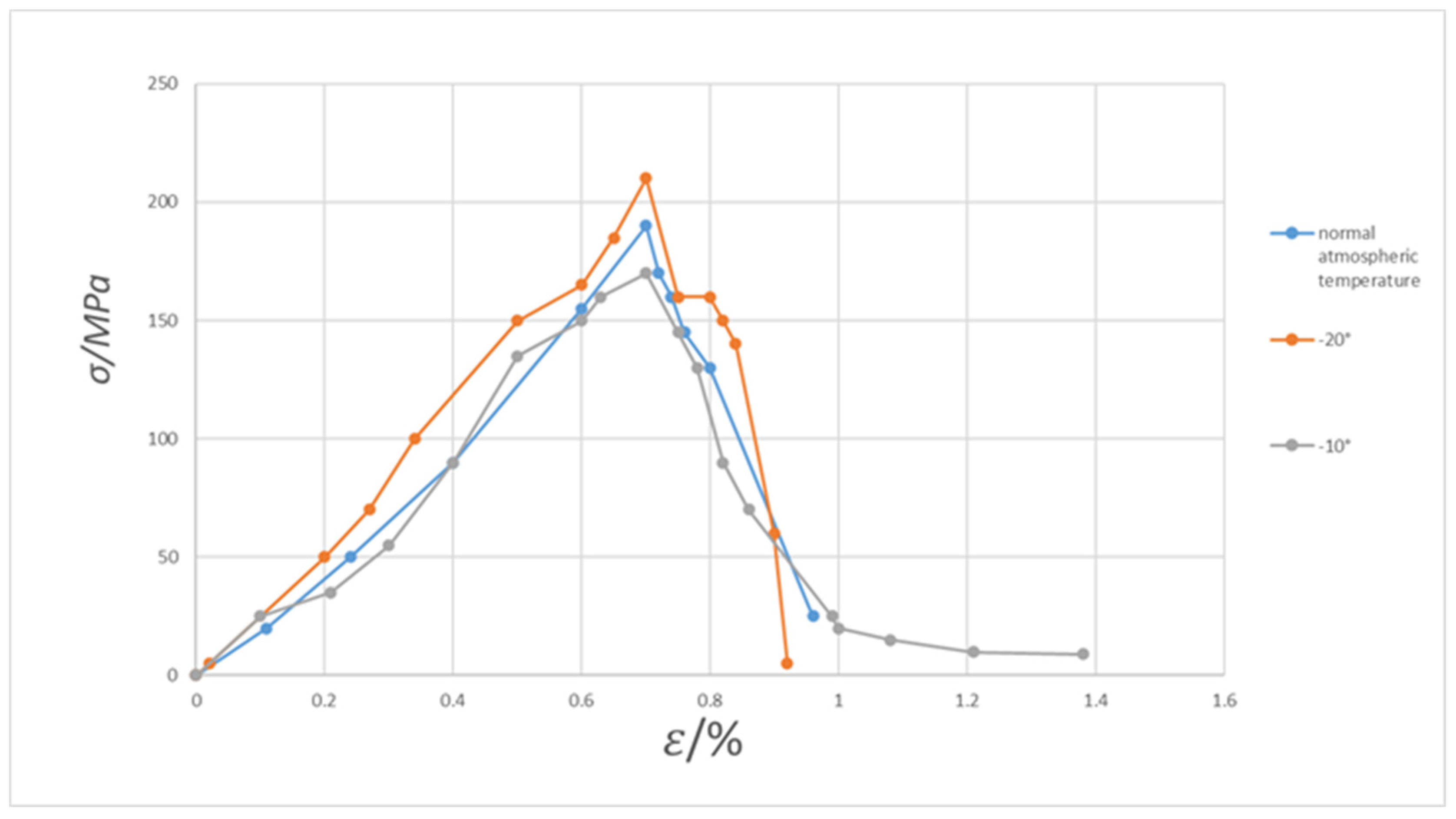
3.3. Study of Mechanical Properties of Frozen Rock

The change of temperature causes the expansion and contraction of the mineral particles that make up the rock. The expansion and contraction of mineral particles will change the microstructure of rock, resulting in the change of rock physical properties. In order to further study the relationship between temperature and rock mechanical properties, simulated mechanical tests were conducted by combining the magnitude of temperature change and the nature of the rocks. Samples from representative sections of the mine (mainly granite) were selected for triaxial compression experiments simulating room temperature and low-temperature environmental conditions (−10 °C and −20 °C). An electro-hydraulic servo material test system was used in the experiment. The experiment process and temperature were controlled by computer. The temperature accuracy of the system was 0.1 °C. The stress–strain curves were plotted according to the results, as in Figure 8.
It can be seen from Figure 8 that the change of temperature had little effect on the stress–strain curve of rock samples. The failure of rock samples was brittle failure at the peak stress point. The change of temperature mainly affected the deformation and failure modes of the rock specimens after loading, which is shown in the figure as a large difference between the horizontal and vertical axes.
It can be seen from Figure 8 that for the full stress–strain curve at −10 °C, the slope before the peak decreased significantly with the decrease in temperature and the failure load decreased. This shows that the stiffness and strength of rock decreased with the decrease in temperature. For the full stress–strain curve at −20 °C, the slope before the peak value obviously steepened with the decrease in temperature and the failure load increased. This shows that the stiffness and strength of rock increased with the decrease in temperature.
The test shows that after the rock sample underwent low temperature, the dynamic modulus was lower than the static modulus within a certain range of variation. The smaller the yield stress of the rock sample, the smaller the compressive strength of the rock. The results show that as the temperature increased, the stiffness and strength of the rock decreased. This reflects the order of difficulty to ease of freezing rock blasting at −20 °C, −10 °C and room temperature (~5 °C to 10 °C).

4. Engineering Cases

4.1. Project Overview

Heilongjiang underground mine is located in the territory of Hailin City, Heilongjiang Province. It is situated in the alpine mountainous area, where the extreme minimum temperature can reach −45.2 °C and the average temperature of rock mass is −5 °C to −15 °C. The bedrock is white granite with hard rocks below weak weathering and high compressive strength. The main object of this blasting program design is the lower plate 3# ore body in Table 9 below. The metal minerals are mainly magnetite, followed by hematite, magnetite hematite with a small amount of metal sulfides and so on. Magnetite content is generally between 15~25%, with an average of 20.90%. Magnetic hematite is generally between 5~13%, with an average of 6.41%. The non-metallic minerals are mainly quartz and actinolite, followed by hornblende, garnet, plagioclase and tremolite.

4.2. Blasting Problems

There are some problems in rock blasting in high cold areas, such as a low requirement of large block rate [29], a high base rate and poor flatness [30]. The mine studied in this paper is located in the Heilongjiang area. The mining area is not only cold in temperature but also has well-developed joints and an obvious layered structure. Many areas are broken, and invisible structure cannot be judged. The above factors lead to the traditional frozen rock blasting problems in this mine being more serious. After the blasting of the mine, there are a series of problems such as large collapse angle, unobvious subsidence ditch, uneven blasting face, bulging and cracking. According to the above joint simulation and frozen rock experiment conclusion, the blasting parameters are designed to improve the mine-blasting effect.

4.3. Optimization of Blasting Parameters

4.3.1. Hole Network Parameters

Mine joints’ fissure development is obvious, with the need to increase the row spacing in order to prolong the action of the blast gas in the hole time. At the same time, the density factor is increased so that the fissure caused by the blasting of the first row of packets extends into the rock area where the latter rows of packets are blasted. The latter rows will not have more rock left in the middle adjacent two packs due to the increased pack spacing. This increases the crushing effect and reduces the rate of large blocks after blasting. Hole network parameters are shown in Table 10.

4.3.2. Explosives Unit Consumption

Work capacity is an important indicator to measure the explosive performance of explosives. The experimental results show that the explosive ability of emulsion explosive was 10% higher than that of ammonium explosive in permafrost under cold conditions. Therefore, high-power explosive No. 2 rock emulsion explosive was selected for the frozen rock burst operation. The explosive performance is shown in Table 11. The comparison of explosive consumption before and after optimization is shown in Table 10.

4.3.3. Blasting Interval Time

In underground mine blasting, a reasonable interval time can effectively improve the blasting quality. The delay time is shown in Table 12.

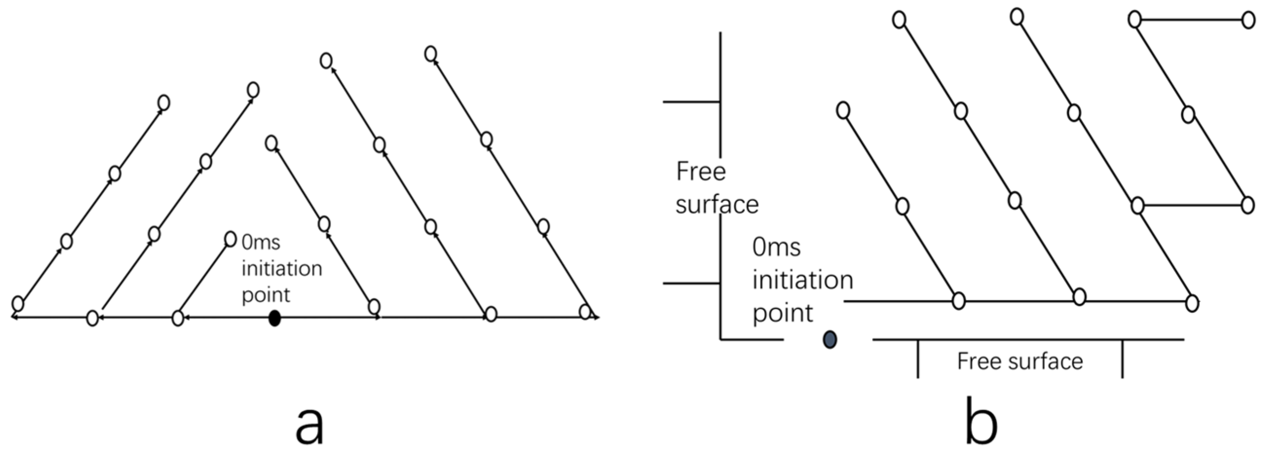
4.3.4. Multi-Nodular Frozen Rock Hole-By-Hole Detonation Technology

Shunt blasting was to adjust the relationship between the direction of the blasting action and the structural surface, using structural surfaces such as joints and fissures in the rock body to improve the blasting quality. The original initiation network adopted the method of inter-row delay initiation. This method had a poor effect in jointed rock mass. The new method was blasted in the forward direction using a multi-row diagonal hole-by-hole and counter-slant multi-row V-shaped hole-by-hole detonation network, which achieved good results. The detonation network after optimization is shown in Figure 9.

4.4. Blasting Optimization Effect

For the blasting of frozen rock in mines with developed joints, No. 2 rock emulsion explosives with a single explosive consumption of 0.55 kg/m3 were used along the blasting direction. The detonation network was multi-row diagonal hole-by-hole and counter-inclined multi-row V-shaped hole-by-hole. After blasting, the large lump rate was low, the distribution of blocks was more uniform, the bottom plate was flat (which is conducive to the subsequent operation), the subsequent blasting operation surface was neater and good engineering results were achieved.

5. Conclusions and Future Work

Based on the actual blasting of underground mines in Heilongjiang, this paper studies the blasting of joints and frozen rocks in view of the sustainable development of resource exploitation in alpine regions. In this paper, blasting parameters are designed to optimize the blasting effect and to reduce the damage effect of blasting on the ecological environment. The main findings are as follows.
(1)
In this paper, numerical simulation analysis was used to grasp the joint development and frost rock blasting crack propagation law. Therefore, the blasting effect of frozen rock can be judged according to different joint conditions to guide the blasting of jointed frozen rock.
(2)
The optimum charging depth and the critical depth of frozen rock were determined by a blasting funnel experiment. The relationship between the stress and strain of frozen rock at different temperatures was compared. Combined with the G-G-S function, the blasting parameters suitable for frozen rock in the mining area were obtained.
(3)
According to the environment and geological conditions of the mining area, the V-type hole-by-hole detonation method of multi-row hole oblique line and anti-inclined multi-row hole was determined. This method achieved a good blasting effect and ensured sustainable mining.
However, this work has limitations. The conclusions obtained are only applicable to jointed frozen rock blasting in alpine regions; the effect is not good for other regions. In engineering practice, there are not only the rock strata selected by this experiment. For rock strata with structural surface, for fractured rock mass or for other buried rock strata, a large number of basic experimental studies are needed to obtain more basic experimental data and to provide references and bases for engineering design. Furthermore, because this paper’s results are only from the three temperature levels of the frozen rock laboratory test, the conclusion needs to be further improved.

Author Contributions

Conceptualization, P.C.; methodology, P.C.; software, Y.L.; validation, Y.L.; formal analysis, Y.L.; investigation, P.C.; resources, S.J.; data curation, S.J.; writing—original draft preparation, Y.L.; writing—review and editing, Y.L.; visualization, P.C.; supervision, S.J.; project administration, C.L.; funding acquisition, H.X. All authors have read and agreed to the published version of the manuscript.

Funding

This research received no external funding.

Informed Consent Statement

Informed consent was obtained from all subjects involved in the study.

Data Availability Statement

The data that support the findings of this study are available from the corresponding author, Y.L., upon reasonable request.

Acknowledgments

This work was supported by National Natural Science Foundation of China: disaster identification and early warning of complex slope in open pit mine based on data knowledge hybrid drive (52104146). We thank the associate editor and the reviewers for their useful feedback that improved this paper.

Conflicts of Interest

The authors declare that there is no conflict of interest regarding the publication of this paper.

References

  1. Wu, Q.; Liu, Y.; Zhang, J.; Tong, C. A review of recent frozen soil engineering in permafrost regions along Qinghai–Tibet Highway, China. Permafr. Periglac. Process. 2002, 13, 199–205. [Google Scholar]
  2. Gao, F.; Zhou, K.; Xiong, X. Present Situation and Key Problems of Metal Mineral Resources Exploitation in high Cold Region of China. Min. Reaearch Dev. 2022, 42, 1–5. [Google Scholar] [CrossRef]
  3. Wei, G.P.; Zhang, S.C.; Zhou, Y.M.; Fei, H.J.; Guo, Z.T. Experimental study on frozen soil blasting in Yihaimuli open coal mine. Eng. Blasting 2017, 23, 1–5+20. [Google Scholar]
  4. Vyalov, S.S.; Yu, K.Z.; Gorodetsky, S.E. Stability of mine workings in frozen soils. Eng. Geol. 1979, 13, 339–351. [Google Scholar] [CrossRef]
  5. Wang, X.R.; Pouyan, A.; Chen, H.; Labuz, J.F. Microcracking in tensile fracture of a brittle rock. Eng. Fract. Mech. 2021, 251, 107789. [Google Scholar] [CrossRef]
  6. Wu, J.Y.; Jing, H.W.; Gao, Y.; Meng, Q.B.; Yin, Q.; Du, Y. Effects of carbon nanotube dosage and aggregate size distribution on mechanical property and microstructure of cemented rockfill. Cem. Concr. Compos. 2022, 127, 104408. [Google Scholar] [CrossRef]
  7. Huang, Z.; Wu, Y.; Zhang, R.; Zhong, W.; Li, S.; Zhang, C.; Zhao, K. Experimental investigation on the grouting characteristics of fractured sandstones under different confining pressures. Geomech. Geophys. Geo-Energ. Geo-Resour. 2022, 8, 201. [Google Scholar] [CrossRef]
  8. Wang, T.; Du, B.; Li, C.; Wang, H.; Zhou, W.; Wang, H.; Lin, Z.; Zhao, X.; Xiong, T. Ecological environment rehabilitation management model and key technologies in plateau alpine coal mine. Coal J. 2021, 46, 230–244. [Google Scholar] [CrossRef]
  9. Liu, W.; Xu, Y.B.; Fan, D.; Li, Y.; Shao, X.F.; Zheng, J.J. Alleviating Corporate Environmental Pollution Threats toward Public Health and Safety: The Role of Smart City and Artificial Intelligence. Saf. Sci. 2021, 143, 105433. [Google Scholar] [CrossRef]
  10. Chang, Z.G.; Ke-Min, L.I.; Ding, X.H.; Li, M.A.; Tao, L.I. Analysis on Influence of Cold Climate on Blasting Safety of Surface Mine. Eng. Blasting 2011, 17, 100–102. [Google Scholar]
  11. Wu, F.; Liu, Y.; Li, H.; Yao, Q. Fragmentation distribution prediction of rockfill materials based on statistical results of primary joints and simulation of blasting cracks. Chin. J. Rock Mech. Eng. 2017, 36, 1341–1352. [Google Scholar]
  12. Gnirk, P.F. On the correlation between explosive crater formation and rock properties. In Proceedings of the 9th U.S. Symposium on Rock Mechanics, Denver, CO, USA, 4 November 1967; pp. 321–345. [Google Scholar]
  13. Zhu, Z.; Yin, Y.; Chen, M.; Wei, D.; Lu, W.; Liu, J. Study on Prediction of Blasting Fragmentation in Changjiu Shenshan Limestone Mine. Blasting 2021, 38, 17–31. [Google Scholar]
  14. Xu, B.; Zhang, W.; Shi, W.; Hao, G.; Liu, X.; Mei, J. Experimental study of parameters of tunneling blasting in jointed layered rock mass. J. China Univ. Min. Technol. 2019, 48, 1248–1255. [Google Scholar]
  15. Li, J.; Zhang, J.; Zou, R.; Wang, S.; He, X. Experimental Study on Bench Blasting of Joint Fissure Rock Mass with High Water Content. Min. Res. Dev. 2018, 38, 6–9. [Google Scholar] [CrossRef]
  16. Zhong, Q.; Leng, Z.; Peng, Z.; Liu, F. Blasting Excavation of Deep Tunnel with Jointed Rock Mass: Damage Properties and Schemes. J. Yangtze River Sci. Res. Inst. 2018, 35, 89–94. [Google Scholar]
  17. Zhao, W.K.; Xia, F.; Chen, X. Causes and solutions of surface chunks of open blasting at Yulong copper mine, Tibet. Min. Res. Dev. 2021, 41, 21–25. [Google Scholar]
  18. Jiang, S.; Li, J.; Zhang, S.; Gu, Q.; Lu, C.; Liu, H. Landslide risk prediction by using GBRT algorithm: Application of artificial intelligence in disaster prevention of energy mining. Process Saf. Environ. Prot. 2022, 166, 384–392. [Google Scholar] [CrossRef]
  19. Jiang, S.; Liu, H.; Lian, M. Multi-source information fusion and displacement prediction of rock slope based on variable selection and SSA-DELM model. Front. Environ. Sci. 1687, 22, 101–189. [Google Scholar]
  20. Li, X.S.; Li, Q.H.; Hu, Y.J.; Teng, L.; Yang, S. Evolution Characteristics of Mining Fissures in Overlying Strata of Stope after Converting from Open-Pit to Underground. Arab. J. Geosci. 2021, 14, 1–18. [Google Scholar] [CrossRef]
  21. Shao, X.F.; Zhong, Y.F.; Liu, W.; Li, Y.R.M. Modeling the effect of green technology innovation and renewable energy on carbon neutrality in N-11 countries? Evidence from advance panel estimations. J. Environ. Manag. 2021, 296, 113189. [Google Scholar] [CrossRef] [PubMed]
  22. Xu, Y.B.; Liu, W.; Pu, R.H.; Xu, Y.H. Be Green to be Innovative: The Role of Government Subsidies. Front. Environ. Sci. 2021, 9, 765100. [Google Scholar] [CrossRef]
  23. Jin, F. Promoting the development of integration and innovation in Northeast China with new infrastructure as a traction. Learn. Explor. 2021, 4, 120–124. [Google Scholar]
  24. Dobratz, M. Properties of chemical explosives and explosive simultants. Int. J. Neurosci. 1981, 51, 339–340. [Google Scholar]
  25. Tang, Y.; Kong, D.-R. Numerical simulation study on the trajectory of three wave points in the explosion field of TNT explosives. J. Test. Technol. 2021, 4, 352–357. Available online: http://kns.cnki.net/kcms/detail/14.1301.TP.20210616.1111.026.html (accessed on 4 November 2022).
  26. Miao, Y.S.; Li, X.; Yan, H.H.; Wang, X.H.; Sun, J. Symmetric Bilinear Initiation Technique in Engineering Blasting. Eng. Blasting 2017, 23, 6–11. [Google Scholar]
  27. Tan, Z.; Kuang, C.; Yang, X.; Wang, M. Research on blasting technology for construction of fenghuoshan tunnel in permafrost. Chinese J. Rock Mech. Eng. 2006, 25, 1056–1061. [Google Scholar]
  28. Ma, Q. Model Test of Explosion Crater and Blast Ability of Frozen Soil. J. China Coal Soc. 1997, 3, 66–71. [Google Scholar]
  29. Yu, J.-X. Crater test of deep shaft frozen soil blasting in west air shaft of Zhaogu No.2 Mine. Coal Eng. 2021, 53, 29–34. [Google Scholar]
  30. Li, C.-C. Study on Optimization of Frozen Soil Blasting Effect in High Latitude and Cold Region. Blasting. 2022. Available online: http://kns.cnki.net/kcms/detail/42.1164.tj.20221115.1107.002.html (accessed on 26 October 2022).
Figure 1. Blasting model diagram of nodular rock body: (a) infinite joint, (b) semi-infinite joint, (c) local short joint. Note: (a,b) the model size is 60 d × 60 d; the gun hole diameter d = 5 mm; R is the distance between the center of the gun hole and the joint; the joint width 0.1 d; σ0 is the static stress at the vertical joint surface; α is the angle of incidence of the stress wave.
Sustainability 14 16479 g001
Figure 2. Influence of semi-infinite joints on the effect of explosive rupture: (a) R/d = 5, no filling; (b) R/d = 5, filling; (c) R/d = 20, filling.
Sustainability 14 16479 g002
Figure 3. Blasting process of rock body containing long joints: (a) t = 6 μs; (b) t = 20 μs; (c) t = 100 μs; 1, frozen rock; 2, blast hole; 3, joint; 4, attenuating medium; 5, blasting stress wave; 6, blasting fissure.
Sustainability 14 16479 g003
Figure 4. Effect of nodal location on the effect of explosive rupture.
Sustainability 14 16479 g004
Figure 5. Effect of static stress on the effect of tensile damage by reflection of joints (R/d = 15).
Sustainability 14 16479 g005
Figure 6. Blasting process at the nodal angle α = 30°:(a) t = 6 μs; (b) t = 30 μs; (c) t = 100 μs.
Sustainability 14 16479 g006
Figure 7. Blasting results for different static stresses and different incidence angles. In the figure: (a1–a5) incident angle 0°, (b1–b5) incident angle 15°, (f1–f5) incident angle 75°, (g1–g5) incident angle 90°; the stresses from 1 to 5 are 0, 10, 20, 30 and 40 MPa, respectively. Note: from (a) to (f) α are 0°, 15°, 75° and 90°, respectively, and from 1 to 5 σ0 are 0 Mpa, 10 Mpa, 20 Mpa, 30 Mpa and 40 Mpa, respectively.
Sustainability 14 16479 g007
Figure 8. Stress–strain curve of rock specimen.
Sustainability 14 16479 g008
Figure 9. Diagram of the detonation network: (a) 1 free-face ‘V’ detonating network; (b) 2 free-face diagonal initiation networks.
Sustainability 14 16479 g009
Table 1. Explosive material parameters.
Density ρ (kg/m3)Explosion Velocity D (m/s)A (GPa)B (GPa)R1R2ωEV (GPa)
163069303717.434.150.950.37
Table 2. Granite parameters.
Temperature
/°C
ρ
(g/cm3)
E0
(GPa)
μσc (MPa)
102.6051.80.33150
−102.6060.10.30163
202.6065.80.28176
Table 3. Joint parameters.
Ρ (g/cm3)E0 (GPa)μEtan (GPa)
1.6020.00.32.5
Table 4. The parameters of ice material model.
ρ (g/m3)G (Pa)SIGY (Pa)BULK (Pa)PRF (Pa)
0.9 g/m32.2 × 1092.12 × 1065.26 × 109−4 × 10⁶
Table 5. The parameters of air material model.
ρ (g/m3)C0C4C5E0V0
1.29 × 10⁻³−1 × 10−60.40.42.5 × 10−61
Table 6. Frozen rock blasting test data.
Name°CBest DepthCritical
Depth
V (×10−6 m3)R (mm)H (mm)0~10 mm10~25 mm25~40 mm
Weight (g)%Weight (g)%Weight (g)%
L11056721566041188.9685326218.32
L2−1035671125732146.939145.055728.22
L3−1050655452.72032.242216.427253.73
L4−106580110524594.50115.506130.50
L6−105570654628139.901913.298458.74
L7−20366037372468.541926.761926.76
L8−20426339382588.662127.232125.33
L9−20355935362478.661826.372026.12
Table 7. Results of regression analysis of R-R distribution function blast block degree.
NameR-R FunctionCorrelation CoefficientTest ValueD0/D50
D0 (mm)aD50 (mm)
−20 °C30.8412.27826.2780.996115.2231.174
−10 °C40.6851.72832.9100.999616.2201.236
−20 °C55.5091.96846.0760.94516.6941.205
10 °C37.5501.92831.4080.9346.8631.209
Table 8. Results of regression analysis of G-G-S distribution function blast block degree.
NameG-G-S FunctionCorrelation CoefficientTest ValueD0/D50
D0 (mm)aD50 (mm)
−10 °C45.0821.67929.8310.98252.6891.509
10 °C51.7791.49832.5990.998509.7501.588
−10 °C71.1061.69347.2150.95822.0631.506
−20 °C51.7351.54233.0000.97432.2161.567
Table 9. Main characteristics of underground iron ore in Heilongjiang.
Ore Body NameInclinationThicknessSolid Mineral RockPermissible Exposed Area of Roof PlateOre Rock Laminations
Lower plate 3# ore body32°−40°10 m–20 mBelow medium solidAbout 600 m2Development, prone to the overall top plate bubble fall
12# ore body
North 3# ore body
Table 10. Optimization Comparison of Hole Network Parameters.
Whether OptimizedPore Size
mm
Step Height
m
Hole Depth
m
Hole Spacing
m
Row Spacing
m
Filling Height
m
Explosive Consumption
kg/m3
Before901012.04.02.0≥20.50
After901011.55.02.5≥20.55
Table 11. No. 2 rock explosive performance indicators.
ProjectsExplosive Distance
≥cm
Explosive Intensity
≥mm
Explosive Speed
≥m/s
Density
g/m3
Expiration Date
DaysValid Period
Explosive Distance
≥cm
Explosive Speed
≥m/s
Performance Indicators3123.2 × 1030.95~1.318033.2 × 103
Table 12. Mine multi-joint frozen rock blasting delay combination (ordinary detonating tube detonator).
Nodal TypeFrozen Rock TemperatureInter-Hole Extension TimeInter-Arrangement Extension TimeIn-Hole Extension Time
SectionTime DelaySectionTime DelaySectionTime Delay
Vertical nodesRoom temperatureMS350 msMS5110 msMS11490 ms
−10 °CMS350 msMS5110 msMS13720 ms
−20 °CMS225 msMS475 msMS13720 ms
Parallel nodesRoom temperatureMS225 msMS475 msMS11490 ms
−10 °CMS225 msMS475 msMS13720 ms
−20 °CMS225 msMS475 msMS13720 ms
Mixed nodesRoom temperatureMS350 msMS5110 msMS11490 ms
−10 °CMS350 msMS5110 msMS13720 ms
−20 °CMS225 msMS475 msMS13720 ms
MS2, MS3, MS4, MS5 error is ±10 ms; MS11 error is ±45 ms; MS13 error is ±50 ms.
Publisher’s Note: MDPI stays neutral with regard to jurisdictional claims in published maps and institutional affiliations.

