Article

Evaluation of the Ground Settlement in an Urban Area Resulting from a Small Curvature Tunneling Construction

1
China Construction Eighth Engineering Division Rail Transit Construction Co., Ltd., Nanjing 210046, China
2
China Construction Infrastructure Co., Ltd., Beijing 100029, China
3
China State Construction Engineering Co., Ltd., Beijing 100029, China
4
Key Laboratory of Concrete and Prestressed Concrete Structures of Ministry of Education, Southeast University, Nanjing 210096, China
5
Department of Civil and Environmental Engineering, School of Engineering and Digital Sciences, Nazarbayev University, Kabanbay Batyr Ave. 53, Nur-Sultan 010000, Kazakhstan
*
Author to whom correspondence should be addressed.
Sustainability 2022, 14(23), 16230; https://doi.org/10.3390/su142316230
Submission received: 20 October 2022 / Revised: 19 November 2022 / Accepted: 29 November 2022 / Published: 5 December 2022
(This article belongs to the Section Environmental Sustainability and Applications)

Abstract

:
The transportation system is one of the major infrastructures in urban areas, and it serves 56% of the world’s population. Nowadays, metro lines are developing fast in urban areas. Due to the restrictions of urban fields, metro lines are usually not planned straight, and a curved line is required to connect stations in different locations in a city. As a result, small curvature tunnels are commonly constructed in urban areas. The tunneling construction in a city area may cause ground settlement, which is sensitive to surrounding buildings and underground utilities. The aim of this study is to explore the impact of curvature alignment on the ground settlement. In this paper, ground settlements induced by small curvature shield tunneling were evaluated by using a numerical analysis. A total of six cases were selected for the analysis. The results obtained from the numerical simulations were compared with Peck’s equation. It is observed that Peck’s equation can be used for the estimation of the maximum settlement. However, the ground settlements on both sides of the central axis of the curved tunnel are asymmetrical, and Peck’s equation, which provides a symmetrical settlement, may not be applicable in the case of small curvature tunnels.

1. Introduction

With the advent of the metro construction boom in China, it has been increasingly crucial to assess the impact of shield-driven tunnels on surrounding underground utilities and buildings. The shield tunneling method has the advantages of a safe operation, high speed, comparatively low cost, and less impact on the environment [1], and it is commonly applied to many tunnel construction sites. In the long run, one can predict that there will be more and more small curvature shield tunnels due to space limitations in metropolitan areas. Compared to straight line tunnels, small curvature tunnels have more critical factors (asymmetric jacking force, overcutting gap, and face stability, etc.), which wreak havoc on tunnel safety [2,3]. The main challenge faced by many researchers is how to control stratum deformation induced by a small curvature.
During small curvature tunneling construction, the characteristics of stratum deformation have not been extensively explored because of the over-cutting gap, which is commonly created between the cutterhead and the tail of the shield machine [4]. In this paper, numerical analyses using Plaxis-3D were adopted to investigate the effect of a curved line on a ground settlement. The simulation results were compared with those obtained from Peck’s equation [5]. It is observed that the 3D effects of the small curvature tunneling construction are obvious and that Peck’s equation may not be applicable for evaluating ground settlements in small curvature tunneling construction.

2. Literature Review

Ground settlement induced by shield tunneling, one of the most apparent effects following tunnel construction, has been investigated since the 1950s [6]. Peck [5] reviewed a series of in-situ settlement datasets and proposed a Gaussian-distribution-form equation to represent the tunnel-excavation-caused settlement. Later, many scholars continuously improved Peck’s equation based on engineering data to widen its applicability [7,8,9]. One can observe that Peck’s equation has been blindly used in tunneling construction regardless of the assumptions adopted in the equation. Loganathan and Poulos as well as Zhang et al. [10,11] attempted to derive an analytical description of ground surface settlement based on this equation. However, they were not successful, and the application of this equation is limited due to its complexity and poor accuracy. Zeng and Huang [12] drew on stochastic medium theory to derive a theoretical solution to soil deformation. In their comparison of two other methods, the predicted surface settlement matched the observed data. Mooney et al. [13] presented a parametric analysis of face pressure, annulus pressure, and grouting pressure based on a finite difference model, exploring how these pressures affected ground settlement. Zhu et al. [14] modified the generalized three-dimensional Hoek–Brown strength criterion to propose a new constitutive model. The model can be applied to highway tunnels in rock masses, and it works reasonably well with the field measurements. Zhang et al. [15] suggested that using artificial intelligence can improve the accuracy of the prediction of ground settlement. Wang et al. [16] conducted research on soil disturbance induced by an earth-pressure-balanced shield under multilayered ground using the three-dimensional discrete element method (3D DEM).
Although extensive research on deriving ground settlement produced by straight line tunnels has been carried out, it is unclear if small curvature tunnels will increase stratum disturbance during the construction phase. In particular, restrictions in urban areas lead to small curvature tunnels settling into a restricted urban field condition [17]. With the rapid development of computer capability and related theories, the numerical method has grown in popularity in relation to examining surface ground settlements induced by tunnel excavation [18]. The numerical method allows researchers to simulate complex situations, where analytical and empirical ones are no longer applicable. For example, thrust force, which plays a crucial role in advancing tunnels, is difficult to calculate using a theoretical method; rather, it can be easily incorporated into finite element modeling (FEM) [19]. With the assistance of FEM, Feng et al. [20] compared numerical simulation and analytical methods to determine the ground settlement of small-radius curved tunnels. It has been verified that an increase in the radius of a curvature is inversely associated with the ground settlement [20]. Deng et al. [4] examined how shield tunneling along a curved segment affected the law of surface settlement, with the results of the theoretical prediction and numerical simulation being in alignment with the field monitoring data. In curved tunnels, the additional thrust, friction force, and grouting pressure were incorporated in a parametric analysis to quantify their impacts on curved tunnels [21].
Over the course of tunnel construction, many engineering accidents have been used to analyze adverse factors related to tunnel excavation, with soil properties, structural stability, and groundwater playing a vital role in tunnel stability. Cai et al. [22] investigated the impact of three-dimensional rotation stress on deep rock tunneling, showing that strengthening the core rock can significantly enhance tunnel stability. Pang et al. [23,24] studied the effects of earthquakes and multi-parameter uncertainty on slope stability, and a stochastic ground motion model was proposed to examine the dynamic reliability of different structures. Meng et al. [25] provided a novel method to evaluate ground settlement during tunnels’ post-construction phase. Collectively, these studies summarize different impacting factors that should be taken into consideration when investigating tunnel-induced ground settlements. However, the tunnel configuration and excavation method are normally neglected when analyzing ground settlement. Much uncertainty still exists about the relation between tunnel alignment (small curvature tunnels) and ground deformation.

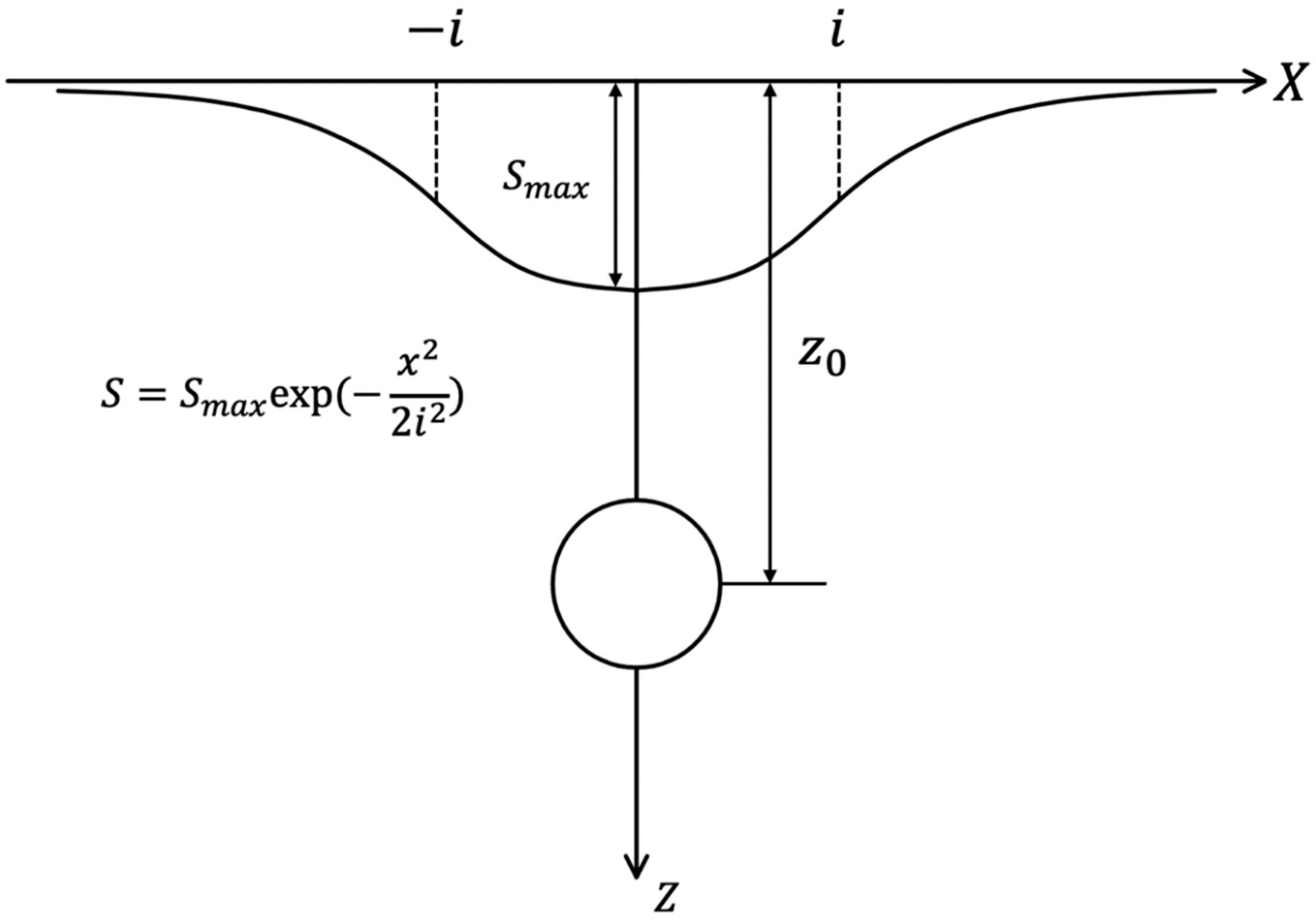
3. Peck’s Equation for Ground Settlement

Peck [5] first proposed the concept of settlement trough induced by tunnel excavation based on the analysis of a large amount of surface settlement data. The settlement trough of a single tunnel is analogous to normal distribution, as shown in Figure 1. He believed that surface settlement was caused by ground loss and that the volume of the surface settlement trough should correspond to the volume of the loss of ground. At that time, he was the first to put forward the horizontal distribution of the surface settlement, and the empirical equation is given in Equations (1) and (2):
S x = S max exp x 2 2 i 2 ,
S max = V s 2 π i ,
where S x is the ground settlement at a distance of x from the central axis of the tunnel; S max is the maximum ground settlement, which is normally located at the center of the settlement curve (x = 0); i is the distance from the center of the settlement curve to the inflection point of the curve, which is generally called the ‘settlement trough width’; x is the distance from the center of the settlement curve to the calculated point; and Vs is the volume of soil loss per unit length.
The width of the settlement trough i and the volume of the soil loss V s are the governing parameters of the ground settlement, which greatly affect the accuracy of the prediction results of the Peck equation. A lot of research on the value of the two parameters has been conducted to give the best-fitted empirical parameters. O’reilly and New [26] modified the settlement trough width i , according to actual geological conditions and relevant construction experience in London:
For cohesive soils:
i = 0.3 Z + 1.1 ,
and for granular soils:
i = 0.28 Z 0.1 ,
where Z is the depth of the tunnel. O’reilly and New [26] also concluded that there is a simple linear relationship between the width of the settlement trough i and the depth of the tunnel Z :
i = Kz 0 ,
K mainly depends on the property of the soil, which is adopted as being 0.5 or 0.25 for clay or sands, respectively.

4. Numerical Modeling

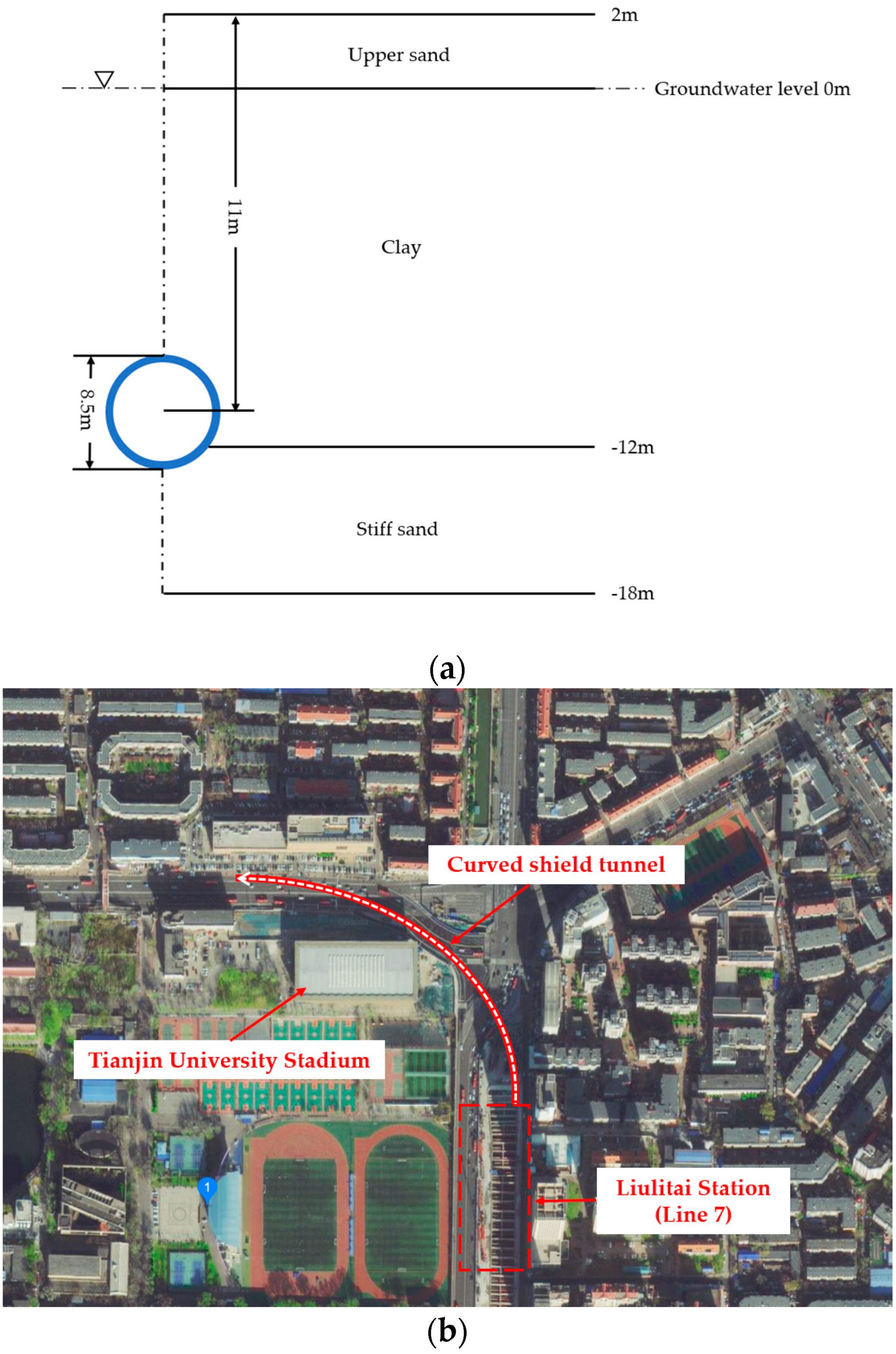
4.1. Geology Used in Numerical Model

Underground soil consists of three layers, with upper sand, clay, and stiff sand, sequentially. From the surface to bottom, the first layer is soft upper sand, with 2 m of depth above the average hydraulic head (0 m). Below the first layer, a clay layer with a 12 m thickness adjoins the upper sand layer (−12 m). The bottom layer is stiff sand, with a 6 m thickness (−18 m). The properties of the three types of soils are listed in Table 1. The Mohr−Coulomb model is adopted in this simulation to describe soil behaviors.
Figure 2a illustrates the cross-section of the soil profile in numerical modeling and the depth of the shield tunnel. The tunnel is buried −11 m below the ground level and is -9 m below the groundwater level. The blue ring represents the outer lining during excavation (Figure 2a), with a thickness of 0.25 m. Additionally, the diameter of the tunnel is 8 m. The whole tunnel diameter is therefore 8.5 m in total.
This project is located between Liulitai Line 7 and Liulitai Line 8, which functions as a connecting line to link two stations with different orientations (Figure 2b). The shield tunnel has a small curvature, and the curvature radius is 180 m. It is the first time in China that a small-radius (180 m) curved shield tunnel has been constructed in a subway field.

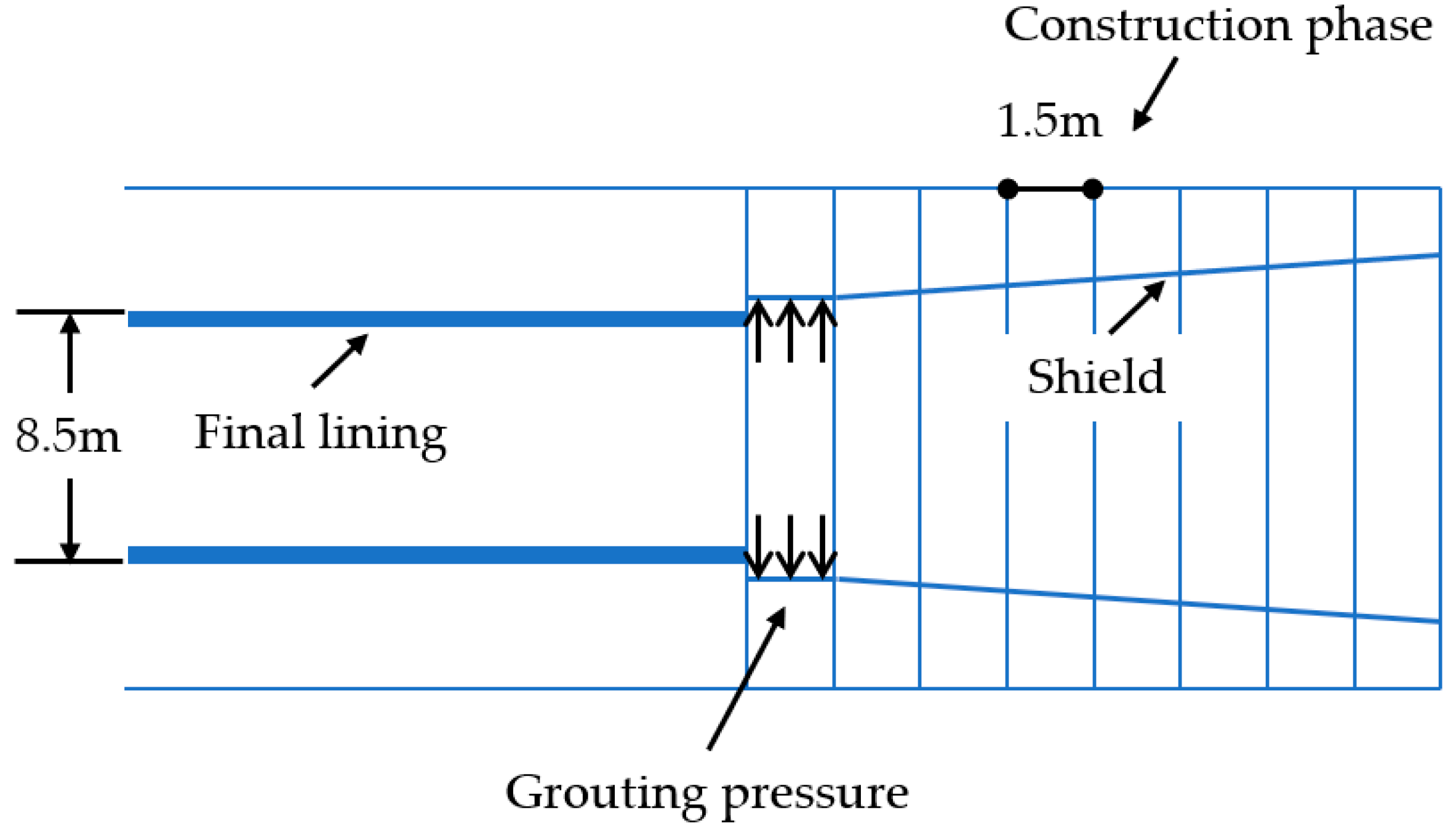
4.2. Tunnel Excavation

Recently, three-dimensional modeling has been extensively applied in tunnel analysis, with the conical shape of the shield machine being modeled by Dias, Kastner, as well as Maghazi, Nematollahi, Molladavoodi, and Dias [27,28]. The conical shape of the shield provides more room for ground deformation, lowers the possibility of shield jamming, and promotes advanced progress [29].
The tunnel excavation is carried out by a 9.0-m-long shield machine. The shape of the shield is exactly conical, i.e., the face and tail have different diameters (Figure 3). While the diameter from the last 1.5 m to the tail of the shield is constant, the first 7.5 m of the shield show decline in diameter. In Plaxis 3D, surface contraction is used to model the volume loss alongside the tunnel lining during excavation [30]. From face to tail, the tunnel has a reduction in volume of 0.5%. The construction process can be divided into construction stages with separate tunnel rings, and each ring is 1.5 m long. In other words, the shield advances 1.5 m within one stage. Therefore, the shield has an axial contraction with an increment C inc = 0.0667 % . In order to model this, a geometry consisting of slices that are each 1.5 m long can be used. The parameters of the shield are listed in Table 2.

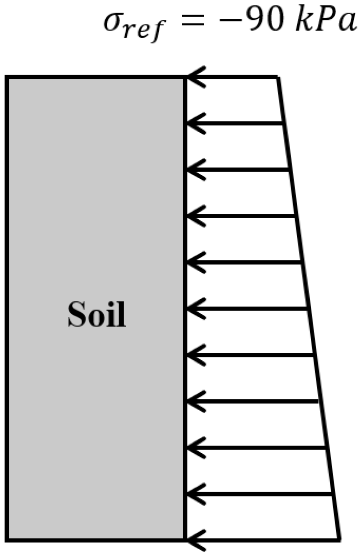
4.3. Excavation Load

During the loading process, each phase needs to model the same parts of the excavation process, including the support pressure at the tunnel face needed to prevent active failure at the face, the installation of the tunnel lining and the grouting of the gap between the soil and the newly installed lining, and the jacking force advancing the shield machine.
The stability of the face is crucial during shield machine excavation. The face pressure acts on the excavation face to support the soil. Face pressure is applied to balance the shield and counteract the resultant total overburden pressure in front of the shield [31]. Since it amounts to the total primary stress above the shield, the top face pressure is 90   kPa with a vertical increment of 14   kPa / m (Figure 4).
In Peck’s equation, the ground settlement is induced by soil volume loss by excavation; in other words, the disturbance by the shield can loosen the stratum, leading to tunnel collapse. Notably, in the specifications of the tunnel-boring process, grouting is used to instantly fill the void after the shield advances [32]. The grouting can be regarded as immediate support for the deformation into the void, which normally leads to small ground settlement. It is estimated that the grout pressure should be 100   kN / m 2 at the top of the tunnel z = 4.75   m and should increase by 20   kN / m 2 per depth, which is slightly larger than the primary stress above it.
To move the shield ahead, jacking force is applied to the final lining segment ring. This is produced by a number of hydraulic jacks located at the shield’s tail. The tunnel lining’s cross-sectional surface is under pressure from the jacks [31]. The jacking force is 635.4   kN / m 2 , with a perpendicular distribution along the last lining segment to advance.
A shield tunnel numerical model should involve procedures to define the excavation method, tunnel-boring machine, sequencing of excavation, surface contraction, face pressure, and grouting pressure.

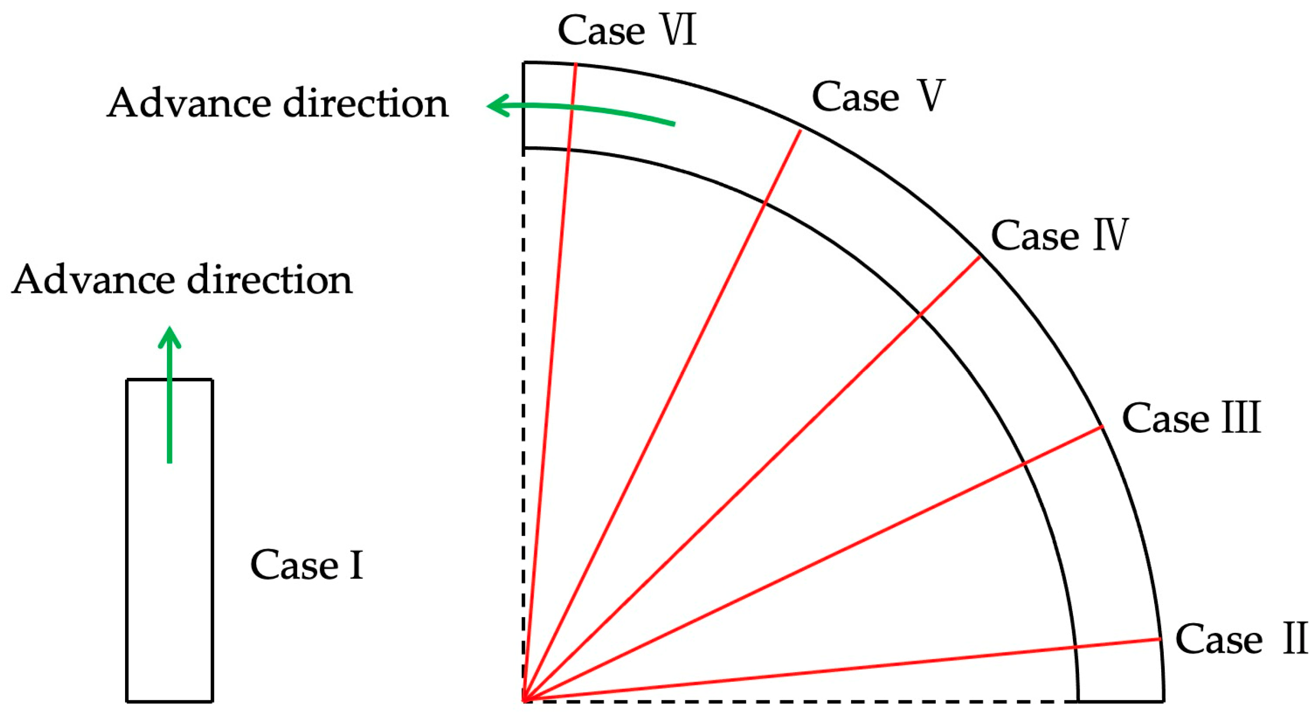
4.4. Excavation Trajectory

In this article, the impacts of different excavation curvatures on ground settlement will be investigated. To assess whether a small curvature excavation increases surface settlement, we measure different patterns of tunnel excavation. The turning radius of the tunnel is approximately 180 m. The modeling processes include one straight tunnel and six sections from different phases of the tunnel.
A tunnel excavation that is in alignment with its central line is set up as a reference model—Case I (Figure 5). We set up a comparison group of five segments partitioning a ¼ of the whole tunnel, which is comprised of 5°, 25°, 45°, 65°, and 85° of the tunnel: Cases II, III, IV, V, and VI (Figure 5). Table 3 presents the simulation cases in modeling.

5. Results and Discussions

In this section, first, the simulation results are compared with those gained from Peck’s equation to identify the impacts of the curved tunnel alignment and the limitation of the Peck equation. Then, the effects on the shape of the settlement curve induced by the curved tunnel alignment are analyzed.

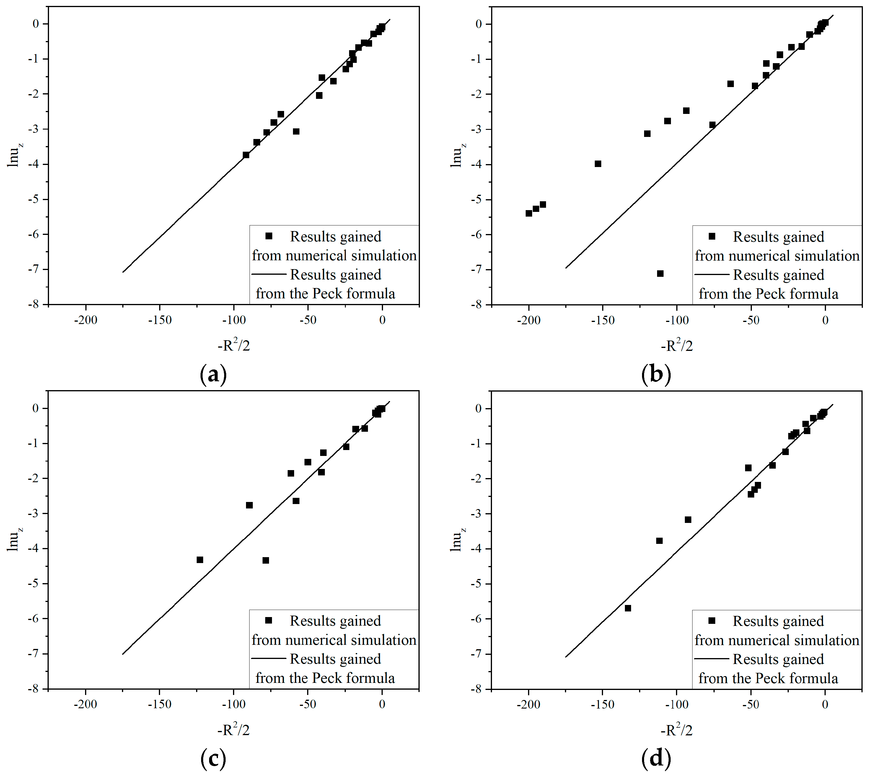
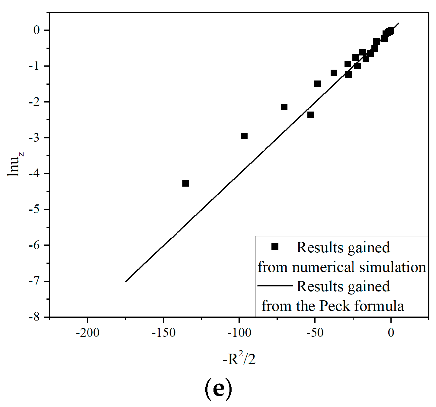
5.1. Comparison with the Results Gained from Peck’s Equation

According to O’reilly and New [26], the i in Peck’s equation was determined as 0.25 for sand and 0.5 for clay. In addition, due to the lack of observation data, the u max was determined through the modified Akima piecewise cubic Hermite interpolation of the numerical results. The interpolation was carried out using the Matlab incorporated function makima.
As shown in Figure 6, the results obtained from the Peck’s equation are plotted with the results obtained from the numerical simulation. u z is the vertical displacement, and R is the horizontal distance from the tunnel axis. This figure is quite revealing in several ways. First, the maximum ground settlement predicted by Peck’s equation is in alignment with the numerical simulation, showing that the correctness of Peck’s equation in predicting the maximum depth is proven. Second, according to the numerical results, the left half of the results is much higher than the right, i.e., the left half is influenced by the overcutting gap existing in the inner side of the tunnel, where the surface soil has a slight ridge. Third, the central line of the maximum depth from the numerical simulation shows a deflection from Peck’s equation because of the small curvature of the tunnel.
In addition, to compare the results more clearly, the results are linearized by plotting lnu z against R 2 / 2 (Figure 7). To quickly determine whether a Gaussian curve can accurately depict the recorded ground settlement curve, Burland et al. [33] changed the form of Peck’s equation into Equations (6) and (7):
S x S max = exp x 2 2 i 2
ln S x S max = 1 2 i 2 x 2
From (6) and (7), there is a linear relationship between ln S x S max and x 2 , and the slope is 1 2 i 2 , which can be used to determine the width of the settlement trough. Therefore, if a sample point set is close to the line gained using Peck’s equation, it may be concluded that this dataset matches well with Peck’s equation and vice versa. From Figure 6 and Figure 7, a mismatch between the results gained from the Plaxis simulation and the results derived from Peck’s equation can be identified, indicating that Peck’s equation, which is generally acknowledged to be applicable to ground surface movement resulting from straight or approximately straight tunnel excavations, seems to be inappropriate for settlements induced by a curved tunnel construction. Moreover, the inconsistency seemingly becomes increasingly severe with an increase in the turning angle of the tunnel.

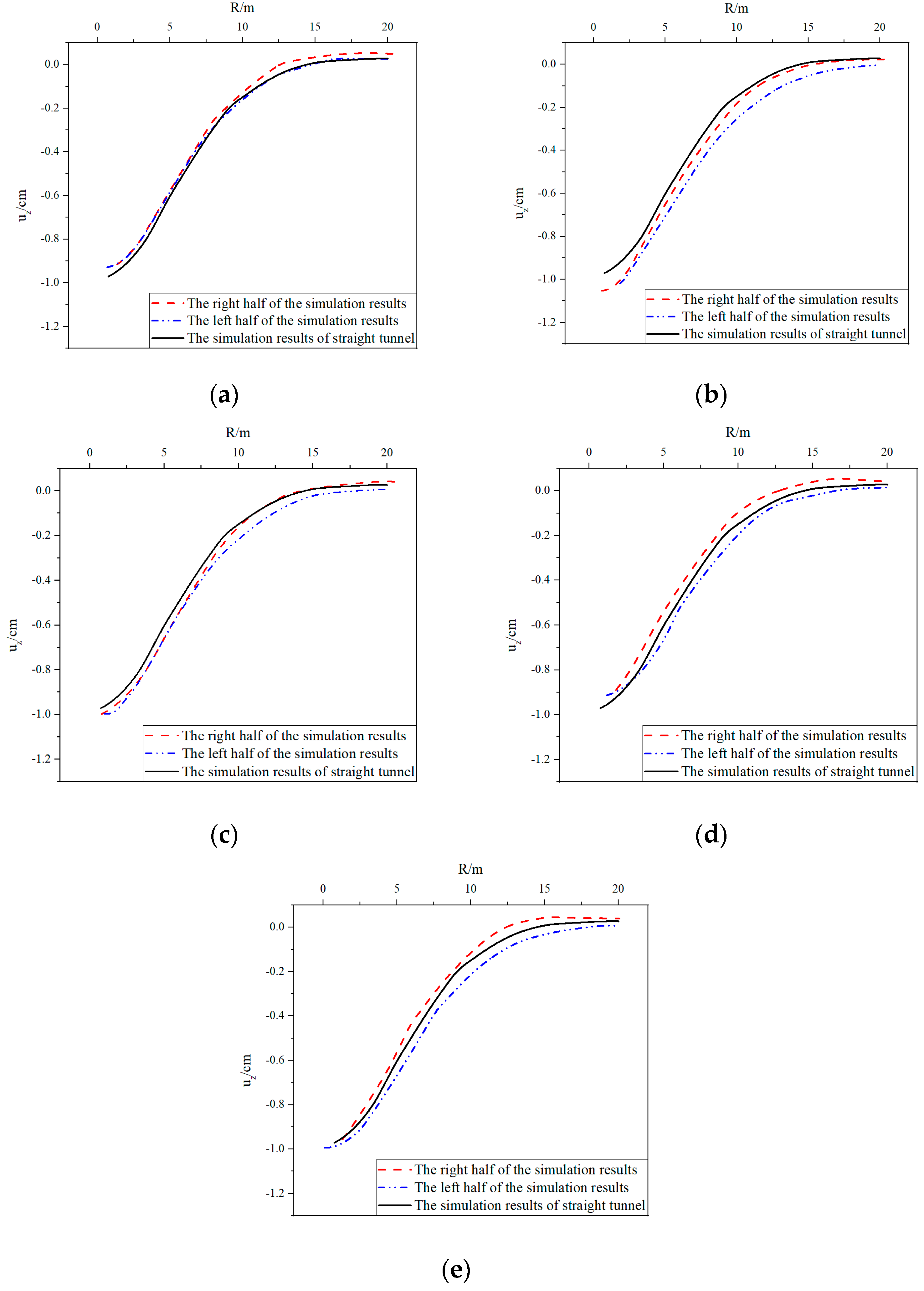
5.2. Analysis of the Shape of the Settlement Curves

From Figure 8, two effects arising from the curvature of the tunnel alignment can be identified—shifting and asymmetry.
The effect of shifting is that the curve appears to shift to the convex side of the curved tunnel. To investigate this effect, the maximum settlements and their corresponding horizontal distances from the tunnel axis of the curved tunnels were derived using Matlab. The values are listed in Table 4.
As demonstrated in Table 4, the coordinates corresponding to the maximum settlements are all positive, which might indicate a shift to the convex side of the curved tunnel. However, since these values were gained using interpolation and the number of sample points was limited, the values in the second column of Table 4 might not be accurate enough to be employed for an analysis of the relationship between the turn angle and shifting distance. In addition, the values in the first column of Table 4 are relatively stable, which implies that the maximum values of the settlements seem irrelevant to the turn angle.
The effect of asymmetry is that the curve, which would otherwise be symmetrical, becomes asymmetrical. As illustrated in Figure 8, to evaluate this effect, the right side of the surface ground movement curve was rotated to the left side around the axis corresponding to the maximum settlement. In addition, the results gained from the straight tunnel simulation were also plotted on the figures to provide a reference.
As shown in Figure 8, the left sides of the curve corresponding to the curved tunnel are below the settlement curve of the straight tunnel, while the right sides are above it. This implies that the curvature of the tunnel alignment may result in larger vertical displacements on the convex side but smaller settlements on the concave side. In addition, the discrepancy between these two sides seems to increase with increments in the turning angle.

6. Conclusions

In this study, numerical simulations were undertaken to analyze the ground surface movement curves of curved tunnels. The results show that Peck’s equation can be used to estimate the maximum ground settlement. However, the 3D effects of the small curvature tunneling are obvious, and Peck’s equation may not be applicable for the evaluation of ground settlements induced by small curvature tunneling construction. Through a comparison between the results obtained from Peck’s equation and the results gained from the numerical simulation, two effects emerging from the curved tunnel were identified—shifting and asymmetry. The shifting effect means that the settlement curve seems to move towards the convex side of the tunnel alignment, and the asymmetry effect is that the settlement curve, which would otherwise be symmetrical, becomes asymmetrical. The horizontal distance data corresponding to the maximum settlements indicate that there is a shifting effect.

Author Contributions

Conceptualization, L.T.; Methodology, S.W.; Validation, J.T.; Investigation, Q.Z.; Resources, W.Y.; Writing—original draft, K.X.; Writing—review & editing, A.S.; Visualization, K.X.; Supervision, J.T.; Project administration, L.T., Q.Z., S.W., W.Y. and B.Z.; Funding acquisition, B.Z. All authors have read and agreed to the published version of the manuscript.

Funding

This research received no external funding.

Institutional Review Board Statement

Not applicable.

Informed Consent Statement

Not applicable.

Data Availability Statement

The data presented in this study are available within the article.

Conflicts of Interest

The authors declare no conflict of interest.

References

  1. Chen, X. Foreword. In Shield Tunnel Engineering; Wang, S., Fu, J., Zhang, C., Yang, J., Eds.; Elsevie: Amsterdam, The Netherlands, 2021; pp. xv–xvi. ISBN 978-0-12-823992-6. [Google Scholar]
  2. Yang, Y.; Zhou, B.; Xie, X.; Liu, C. Characteristics and Causes of Cracking and Damage of Shield Tunnel Segmented Lining in Construction Stage—A Case Study in Shanghai Soft Soil. Eur. J. Environ. Civ. Eng. 2018, 22, s213–s227. [Google Scholar] [CrossRef]
  3. Shi, C.; Wang, Z.; Gong, C.; Liu, J.; Peng, Z.; Cao, C. Prediction of the Additional Structural Response of Segmental Tunnel Linings Induced by Asymmetric Jack Thrusts. Tunn. Undergr. Space Technol. 2022, 124, 104471. [Google Scholar] [CrossRef]
  4. Deng, H.-S.; Fu, H.-L.; Yue, S.; Huang, Z.; Zhao, Y.-Y. Ground Loss Model for Analyzing Shield Tunneling-Induced Surface Settlement along Curve Sections. Tunn. Undergr. Space Technol. 2022, 119, 104250. [Google Scholar] [CrossRef]
  5. Peck, R.B. Deep Excavations and Tunneling in Soft Ground. In Proceedings of the 7th ICSMFE, Mexico City, Mexico, 29 August 1969; pp. 225–290. [Google Scholar]
  6. Islam, M.S.; Iskander, M. Twin Tunnelling Induced Ground Settlements: A Review. Tunn. Undergr. Space Technol. 2021, 110, 103614. [Google Scholar] [CrossRef]
  7. Li, Y.; Lin, J.; Yan, S.; Du, J. Modification of the Peck Formula for a Double-Track Shield Tunnel under Expressway Subgrade. Symmetry 2022, 14, 1904. [Google Scholar] [CrossRef]
  8. Gao, Y.; Liu, Y.; Tang, P.; Mi, C. Modification of Peck Formula to Predict Surface Settlement of Tunnel Construction in Water-Rich Sandy Cobble Strata and Its Program Implementation. Sustainability 2022, 14, 14545. [Google Scholar] [CrossRef]
  9. Zhang, Q.; Wu, K.; Cui, S.; Yu, Y.; Zhang, Z.; Zhao, J. Surface Settlement Induced by Subway Tunnel Construction Based on Modified Peck Formula. Geotech. Geol. Eng. 2019, 37, 2823–2835. [Google Scholar] [CrossRef]
  10. Loganathan, N.; Poulos, H.G. Analytical Prediction for Tunneling-Induced Ground Movements in Clays. J. Geotech. Geoenviron. Eng. 1998, 124, 846–856. [Google Scholar] [CrossRef]
  11. Zhang, D.-M.; Huang, Z.-K.; Li, Z.-L.; Zong, X.; Zhang, D.-M. Analytical Solution for the Response of an Existing Tunnel to a New Tunnel Excavation Underneath. Comput. Geotech. 2019, 108, 197–211. [Google Scholar] [CrossRef]
  12. Zeng, B.; Huang, D. Soil Deformation Induced by Double-O-Tube Shield Tunneling with Rolling Based on Stochastic Medium Theory. Tunn. Undergr. Space Technol. 2016, 60, 165–177. [Google Scholar] [CrossRef]
  13. Mooney, M.A.; Grasmick, J.; Kenneally, B.; Fang, Y. The Role of Slurry TBM Parameters on Ground Deformation: Field Results and Computational Modelling. Tunn. Undergr. Space Technol. 2016, 57, 257–264. [Google Scholar] [CrossRef]
  14. Zhu, H.; Zhang, Q.; Huang, B.; Zhang, L. A Constitutive Model Based on the Modified Generalized Three-Dimensional Hoek–Brown Strength Criterion. Int. J. Rock Mech. Min. Sci. 2017, 98, 78–87. [Google Scholar] [CrossRef]
  15. Zhang, K.; Lyu, H.-M.; Shen, S.-L.; Zhou, A.; Yin, Z.-Y. Evolutionary Hybrid Neural Network Approach to Predict Shield Tunneling-Induced Ground Settlements. Tunn. Undergr. Space Technol. 2020, 106, 103594. [Google Scholar] [CrossRef]
  16. Wang, J.; Feng, K.; Wang, Y.; Lin, G.; He, C. Soil Disturbance Induced by EPB Shield Tunnelling in Multilayered Ground with Soft Sand Lying on Hard Rock: A Model Test and DEM Study. Tunn. Undergr. Space Technol. 2022, 130, 104738. [Google Scholar] [CrossRef]
  17. Zhang, M.; Li, S.; Li, P. Numerical Analysis of Ground Displacement and Segmental Stress and Influence of Yaw Excavation Loadings for a Curved Shield Tunnel. Comput. Geotech. 2020, 118, 103325. [Google Scholar] [CrossRef]
  18. Fang, K.; Yang, Z.; Jiang, Y.; Sun, Z.; Wang, Z. Surface Subsidence Characteristics of Fully Overlapping Tunnels Constructed Using Tunnel Boring Machine in a Clay Stratum. Comput. Geotech. 2020, 125, 103679. [Google Scholar] [CrossRef]
  19. Hasanpour, R.; Rostami, J.; Thewes, M.; Schmitt, J. Parametric Study of the Impacts of Various Geological and Machine Parameters on Thrust Force Requirements for Operating a Single Shield TBM in Squeezing Ground. Tunn. Undergr. Space Technol. 2018, 73, 252–260. [Google Scholar] [CrossRef]
  20. Feng, X.; Wang, P.; Liu, S.; Wei, H.; Miao, Y.; Bu, S. Mechanism and Law Analysis on Ground Settlement Caused by Shield Excavation of Small-Radius Curved Tunnel. Rock Mech. Rock Eng. 2022, 55, 3473–3488. [Google Scholar] [CrossRef]
  21. Li, S.; Zhang, M.; Li, P. Analytical Solutions to Ground Settlement Induced by Ground Loss and Construction Loadings during Curved Shield Tunneling. J. Zhejiang Univ. Sci. A 2021, 22, 296–313. [Google Scholar] [CrossRef]
  22. Cai, W.; Zhu, H.; Liang, W. Three-Dimensional Stress Rotation and Control Mechanism of Deep Tunneling Incorporating Generalized Zhang–Zhu Strength-Based Forward Analysis. Eng. Geol. 2022, 308, 106806. [Google Scholar] [CrossRef]
  23. Pang, R.; Xu, B.; Zhou, Y.; Song, L. Seismic Time-History Response and System Reliability Analysis of Slopes Considering Uncertainty of Multi-Parameters and Earthquake Excitations. Comput. Geotech. 2021, 136, 104245. [Google Scholar] [CrossRef]
  24. Pang, R.; Zhou, Y.; Chen, G.; Jing, M.; Yang, D. Stochastic Mainshock–Aftershock Simulation and Its Applications in Dynamic Reliability of Structural Systems via DPIM. J. Eng. Mech. 2022, 149, 04022096. [Google Scholar] [CrossRef]
  25. Meng, F.; Chen, R.; Kang, X. Effects of Tunneling-Induced Soil Disturbance on the Post-Construction Settlement in Structured Soft Soils. Tunn. Undergr. Space Technol. 2018, 80, 53–63. [Google Scholar] [CrossRef]
  26. O’Reilly, M.P.; New, B.M. Settlements Above Tunnels in the United Kingdom—Their Magnitude and Prediction; Institution of Mining and Metallurgy: London, UK, 1982. [Google Scholar]
  27. Dias, D.; Kastner, R.; Maghazi, M. Three Dimensional Simulation of Slurry Shield Tunnelling. In Geotechnical Aspects of Underground Construction on Soft Ground; August Aimé Balkema: Rotterdam, The Netherlands, 2000; pp. 351–356. [Google Scholar]
  28. Nematollahi, M.; Molladavoodi, H.; Dias, D. Three-Dimensional Numerical Simulation of the Shiraz Subway Second Line—Influence of the Segmental Joints Geometry and of the Lagging Distance between Twin Tunnels’ Faces. Eur. J. Environ. Civ. Eng. 2020, 24, 1606–1622. [Google Scholar] [CrossRef]
  29. Hasanpour, R.; Rostami, J.; Ünver, B. 3D Finite Difference Model for Simulation of Double Shield TBM Tunneling in Squeezing Grounds. Tunn. Undergr. Space Technol. 2014, 40, 109–126. [Google Scholar] [CrossRef]
  30. Bentley PLAXIS 3D-Reference Manual 2022. Available online: https://communities.bentley.com/products/geotech-analysis/w/wiki/46137/manuals---plaxis (accessed on 28 November 2022).
  31. Jallow, A.; Ou, C.-Y.; Lim, A. Three-Dimensional Numerical Study of Long-Term Settlement Induced in Shield Tunneling. Tunn. Undergr. Space Technol. 2019, 88, 221–236. [Google Scholar] [CrossRef]
  32. Kasper, T.; Meschke, G. On the Influence of Face Pressure, Grouting Pressure and TBM Design in Soft Ground Tunnelling. Tunn. Undergr. Space Technol. 2006, 21, 160–171. [Google Scholar] [CrossRef]
  33. Burland, J.B.; Standing, J.R.; Jardine, F.M. Assessing the Risk of Building Damage Due to Tunnelling—Lessons From the Jubi-lee Line Extension, London. In Proceedings of the Fourteenth South-East Asian Geotechnical Conference, Hong Kong, 10–14 December 2001. [Google Scholar]
Figure 1. Settlement trough by tunnel excavation.
Sustainability 14 16230 g001
Figure 2. (a) Location of the tunnel and the soil profile; (b) layout of the project site.
Sustainability 14 16230 g002
Figure 3. Geometry and construction phase of TBM.
Sustainability 14 16230 g003
Figure 4. Face pressure through support.
Sustainability 14 16230 g004
Figure 5. Simulation cases with different turning angles.
Sustainability 14 16230 g005
Figure 6. Results obtained from numerical simulation vs. results gained from the Peck equation; (a) Case II: 5° of tunnel segments; (b) Case III: 25° of tunnel segments; (c) Case IV: 45° of tunnel segments; (d) Case V: 65° of tunnel segments; (e) Case VI: 85° of tunnel segments.
Sustainability 14 16230 g006
Figure 7. Linearized results. (a) Case II: 5° of tunnel segments; (b) Case III: 25° of tunnel segments; (c) Case IV: 45° of tunnel segments; (d) Case V: 65° of tunnel segments; (e) Case VI: 85° of tunnel segments.
Sustainability 14 16230 g007aSustainability 14 16230 g007b
Figure 8. Analysis of symmetry of settlement curve; (a) Case II: 5° of tunnel segments; (b) Case III: 25° of tunnel segments; (c) Case IV: 45° of tunnel segments; (d) Case V: 65° of tunnel segments; (e) Case VI: 85° of tunnel segments.
Sustainability 14 16230 g008
Table 1. Soil properties of three soils in model, which were obtained from the soil investigation report.
SoilThickness (m)Unit Weight (kN/m3)Young’s Modulus (kN/m2)Poisson’s
Ratio
Cohesion
(kN/m2)
Friction Angle
(°)
Upper Sand220 1.3 × 10 4 0.3131
Clay1218 1.0 × 10 4 0.35525
Stiff Sand620 7.5 × 10 4 0.3131
Table 2. Parameters of the tunnel-boring machine.
MethodThickness (m)Diameter of the Cylinder (m)Length of TBM (m)Unit Weight (kN/m2)
Shield0.178.59.0247
Table 3. Six cases used during modeling for comparison.
ConditionTunnel Modeling Trajectory
Case I25 m straight line
Case II25 m straight line with 5° deflection
Case III25° of the shield tunnel
Case IV45° of the shield tunnel
Case V65° of the shield tunnel
Case VI85° of the shield tunnel
Table 4. The maximum settlements and corresponding coordinates.
u z m a x   ( cm ) R (m)
Case I0.980
Case II0.930.38
Case III1.060.19
Case IV1.000.48
Case V0.930.09
Case VI0.990.03
Publisher’s Note: MDPI stays neutral with regard to jurisdictional claims in published maps and institutional affiliations.

