Review

Sustainable Fly Ash Based Geopolymer Binders: A Review on Compressive Strength and Microstructure Properties

1
Department of Civil Engineering, Veer Surendra Sai University of Technology, Burla 768018, India
2
Department of Mechanical Engineering, Veer Surendra Sai University of Technology, Burla 768018, India
*
Author to whom correspondence should be addressed.
Sustainability 2022, 14(22), 15062; https://doi.org/10.3390/su142215062
Submission received: 26 September 2022 / Revised: 3 November 2022 / Accepted: 9 November 2022 / Published: 14 November 2022
(This article belongs to the Special Issue Advances in Sustainable Construction and Building Materials)

Abstract

:
As a result of global warming, the pursuance of low-carbon, sustainable building materials has been prioritized. The development of geopolymer/cement-less binders can be considered an innovative and green way forward to minimize carbon footprint and tackle industrial waste material utilization. However, the chemical composition and properties of industrial waste-derived geopolymer binders varies considerably based on the chemical compositions of the source materials. This review paper presents a comprehensive understanding of the role of different chemical compositions (namely SiO2, Al2O3, CaO, Fe2O, and MgO) available in contemporary industrial wastes and the development of geopolymer binders. Subsequently, the compressive and microstructure properties of various FA-based geopolymer binders have been discussed to exhibit the feasibility of FA as a reliable source material. Significant findings and research gaps have been considered to aid future research works. Indeed, they provide guidelines for the commercial implementation of FA-based geopolymer binders as a low-carbon alternative to Portland cement.

1. Introduction

Cement production contributes nearly 5–8% of global CO2 emissions [1]. For this reason, issues such as climate change, due to global warming, are considered severe areas of concern. In order to significantly scale down carbon emissions, efforts have been made to develop and implement greener alternatives to cement. The greener (low-carbon) alternatives could not only curb carbon emissions, but also provide an effective waste management strategy to achieve the sustainable development goals of the 21st century. Geopolymer (cement-less) binders are the most promising green building material. Figure 1 demonstrates the use of industrial wastes for the production of geopolymer composites which, from an environmental perspective, leads to several benefits.
Since the inception of the term ‘geopolymers’ by J. Davidovits in 1978, research and development in the field of geopolymers has steadily increased and is now considered a highly dynamic area of scientific investigation from both the commercial and environmental viewpoint. The formation of geopolymers includes a reaction between aluminosilicate raw materials (industrial wastes) and an aqueous alkaline composition (usually a mixture of alkali hydroxides and silicates). The result is the inorganic polymer matrix, consisting of a three-dimensional framework of covalently bonded Si-O-Al-O (polysialate), with outstanding strength and microstructural and durable properties compared to cement-based materials [2,3,4,5,6]. However, as proposed in various studies [7,8,9], the reaction mechanism is a multiphase and complex process and still requires extensive investigation.
On the other hand, the rise in manufacturing industries calls for effective industrial waste management strategies. Therefore, developing industrial waste-derived geopolymer binders could potentially be the solution, promoting the concept of a circular economy—waste to wealth [7,8]. The various industrial wastes contain a significant amount of aluminium (Al) and silicon (Si), which are essential for the formation of a strong and durable geopolymer matrix [9,10] and serve as source material in the preparation of geopolymer binders. In some studies [11,12], the presence of magnesium oxide (Mg) and iron (Fe), alongside Al and Si, in some source materials have also been reported to be beneficial for the strength development of resulting geopolymer binders. For this reason, the utilization of such wastes for the production of eco-friendly mortars and concrete could be a step forward in reducing our dependence on cement [13].
Over the last decade, numerous researchers have determined FA as an exceptional geopolymer binder due to its physical and chemical characteristics, aiding in geopolymerization reactions. A high amount of alumino silicate content in fly ash facilitates increased reactivity, with a higher degree of geopolymerization in an alkaline environment, while supporting the reduction of hydration heat and thermal cracking. The development of aluminosilicate gel and the early strength gain of FA-based geopolymers has been demonstrated upon premature high-temperature curing while increasing the rate of geopolymerization due to the requirement of higher activation energy of fly ash. Due to their amorphous nature, FA-based geopolymers possess excellent durability against acid and alkali attacks compared with other geopolymer binders.
This review article discusses some of the latest developments in FA-based geopolymer binders with-GGBFS, RM, IOT, FCA, MK, and SF as source material combinations. Particular focus has been given to the use of these contemporary wastes that require sincere attention to be reused in order to avoid the deterioration of the environment. Particular emphasis has been provided on the role of chemical compositions of these wastes during geopolymerization. There is a lack of studies that clearly describe the role of these particular wastes. However, this paper does not intend to offer an in-depth overview of all the factors/properties of FA-based geopolymer binders. Instead, it emphasizes the importance and selection of source materials for geopolymerization. Further, it concentrates only on the compressive strength and microstructure properties (XRD, SEM, FTIR).

2. Scope of the Study

The current knowledge regarding geopolymers suggests that the selection of source material is crucial for enabling enhanced end properties. The source materials, whose reactivity is maximum and could be readily dissolved, facilitate a better degree of polymerization, thus requiring less curing time. To this end, FA is considered to be an effective source material, owing to its availability, reactivity and chemical compositions, which in turn provide superior properties to the final geopolymer products. Several researchers have therefore investigated many such industrial wastes as a primary or secondary source, along with fly ash as a material combination [14,15].
It is understood from the past literature that the chemical property is the deciding factor when selecting the source materials for the production of geopolymer binders. Hence, the scope of this review includes the initial discussion of the chemical compositions (SiO2, Al2O3, CaO, Fe2O3, MgO) of the desired source materials (FA, GGBFS, RM, IOT, FCA, MK, SF) and their influence upon the geopolymer binder structure formation. It is worth reiterating that this study primarily reviews the properties of FA-based geopolymer binders in two sections: Part-I looks at the compressive strength properties, and part-II at the microstructure properties (XRD, SEM, FTIR) of the geopolymer binder system, derived from FA in combination with IOT, RM, FCA, GGBFS, MK, SF (respectively).

3. Chemical Properties of Industrial Wastes/Source Materials

The rise in the manufacturing industries to attend to the needs of 21st-century civilization has led to a significant generation of industrial waste. With the ultimate aim of achieving a circular economy and sustainable development, these wastes could be utilized efficiently for making geopolymer binders. It is imperative to study the chemical properties of each of these wastes before their implementation as source materials. The chemical compositions play a significant role in the formation of the geopolymer network (Si-O-Al-O), geopolymer gels (C-A-S-H/N-A-S-H) [16,17,18], that in turn determine the strength and other characteristics of the final product. Hence, understanding geopolymer binders requires the utmost attention to the chemistry involved. The SiO2 and Al2O3 content in the source materials are responsible for the formation of the principal geopolymer network (-Si-O-Al-), while the CaO, Fe2O3, MgO contents provide additional mineral compounds, such as calcium aluminosilicate hydrate (C-A-S-H), magnesium aluminosilicate hydrate (M-A-S-H) and ferrosiliate (-Fe-O-Si-O-) type gels, respectively. These additional mineral phases improve the binder matrix, leading to a denser binder structure. Therefore, in this section, the authors’ primary focus is on the chemical properties, and in particular, SiO2, Al2O3, CaO, Fe2O3, MgO of FA, GGBFS, RM, IOT, FCA, MK and SF, before moving toward the strength and microstructure properties.
According to Davidovits, geopolymerization involves the formation of the Si-O-Al-O network [19]. Therefore, the presence of a high amount of Si and/or Al makes industrial waste a potential candidate for geopolymerization. However, apart from oxides of Si and Al, the oxides of Ca, Fe, and Mg are also responsible for geopolymer compound formation. These minerals co-exist alongside the primary polymer chain of Si-O-Al-O-, which further influences the strength of the overall binder matrix.
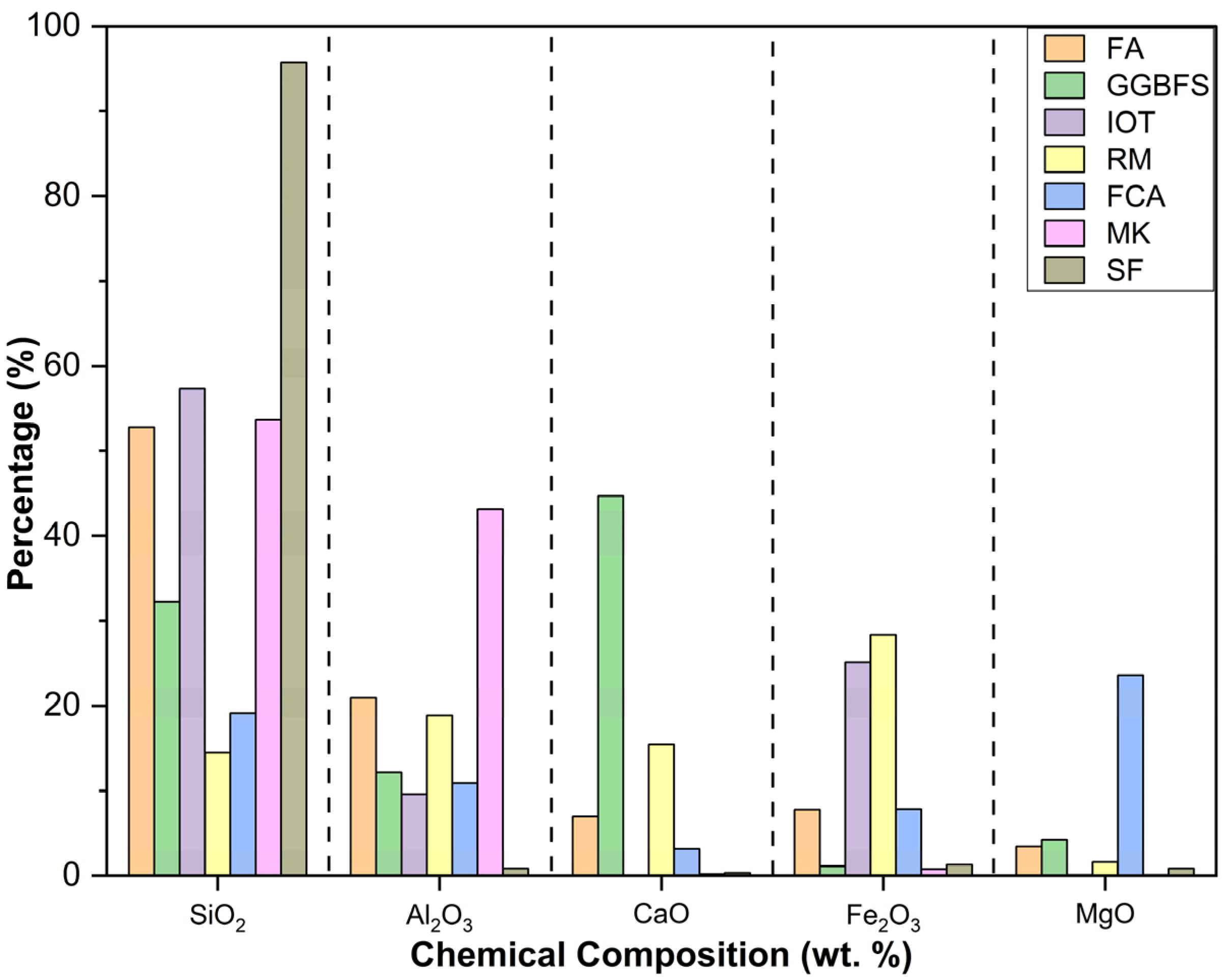
The chemical compositions (esp. SiO2, Al2O3, CaO, Fe2O3, MgO %) of the FA, GGBFS, IOT, RM, FCA, MK, and SF are graphically presented in Figure 2. Table 1 shows that the chemical compositions of each of these wastes vary across the source of their origin (region) and method of processing.

Role of SiO2, Al2O3, CaO, Fe2O3, and MgO in the Formation of Geopolymer Binder Structure

The reaction process leading to the formation of a geopolymer binder structure is complicated and is controlled by various parameters [52]. The most significant factor remains the reactivity of SiO2, Al2O3, CaO, MgO, and Fe2O3 present in the source materials used, which are discussed herein.
The initial step, in the case of geopolymerization, is the dissolution of SiO2 and Al2O3 from the source materials under an alkaline environment, which leads to the development of Si-OH and Al-OH bonds [53]. Subsequently, due to subsequent condensation and polymerization reactions, a 3D network structure is produced that involves the tetrahedral networks of [SiO4] and [AlO4], linked via shared oxygen atoms [54]. However, these tetrahedral connection types of [SiO4] and [AlO4] are often very distinct and intricate; therefore, it can be implied that the properties of the final geopolymer product vary with different connection types [19]. For this reason, it is crucial to select source materials with an optimum composition of SiO2 and Al2O3 in order to achieve enhanced geopolymer properties [20].
The CaO in the source materials does not participate in the core geopolymer network formation, i.e., Si-O-Al-. However, it aids in the formation of hydration products such as C-S-H (a space-filler) and a geopolymer gel, i.e., C-A-S-H, inside the geopolymer binder structure [55]; however, this geopolymer gel also comprises of Al and Si in a tetrahedral connection type, as mentioned earlier. It is also acknowledged that the final orientation and properties of geopolymer structures vary depending on the CaO content in the source materials [56]. Several researchers have favored the presence of CaO in the source materials to achieve improved properties [57,58,59,60]. Furthermore, the hardening time of geopolymers is also significantly affected by the presence of low/high CaO content in the source material [61]; hence, the role of CaO is considered crucial during the selection of source material for geopolymerization.
The presence of iron oxide (from the iron-rich source materials) is indicated by the replacement of Al3+ by Fe3+ (ferric ions) in the geopolymer binder structure (Si-O-Al), yielding a Ferro-sialate network (-Fe-O-Si-O-Al-O-) [62,63]. In contrast, some studies in the past have also found that iron, in its Fe2+ (ferrous) state, remains inert and does not participate in the geopolymerization process [64]. However, Lemougna et al. [65] noticed that some of the ferrous ions are present in the tetrahedral connections of the Si-O-Al network. This observation is corroborated by Kaze et al. [66], who reports that crystalline phases of ferrous ions exist, such as fayalite and siderite, in the final geopolymer binder system. Hence, it is confirmed that the presence of iron in its ferric or ferrous state affects the performance of the geopolymer binder structure and its formation.
The role of MgO in the source materials has been studied in [11,67,68]. It is demonstrated that the existence of MgO did not aid in developing or reorganizing the geopolymer chain (Si-O-Al). However, its presence led to the formation of hydrotalcite. This magnesium and aluminium hydroxycarbonate mineral form act as a filler agent while aiding in accelerating the generation of hydration products such as C-S-H. This reveals that, although MgO does not participate in the core development of geopolymer tetrahedral network formation, it necessitates forming other chemical compounds that directly affect the final geopolymer binder structure.
In this section, it is understood that it is a matter of significance to study the chemical compositions of the source materials (FA, GGBFS, IOT, RM, FCA) and their involvement in the formation of binder structure, which will ultimately influence the end properties. In this context, it is now essential to understand the effect of these source materials on the properties (esp. compressive strength and microstructure), and the subsequent sections (Part I and II) attempt to study this exclusively.

4. Part I: Review of Compressive Strength Properties

The industrial wastes considered for this study-FA, GGBFS, IOT, RM, FCA, MK, SF- carry unique chemical compositions of SiO2, CaO, Fe2O3, Al2O3, MgO % (see Table 1). Different combinations of these source materials have been investigated worldwide to prepare geopolymer binders. However, in this section, the authors have first discussed the compressive strength properties of the geopolymer binders resulting from 100% FA, a combination of FA and GGBFS, followed by the RM, IOT, FCA, MK, SF-based geopolymer binders combined with FA. FA is widely available and is a worthy candidate for geopolymerization because of its chemical composition and easy availability. For the clarity of readers, it is also mentioned that the source material compositions containing only 100% FA are not considered for this review study. This is because the geopolymers prepared from 100% FA has certain limitations, such as a slow setting (100% FA) [69] and low early-age strength gain (100% FA) [70]. In addition, the geopolymerization of other industrial wastes is beneficial from waste management and environmental protection perspectives. Hence, efforts have been made worldwide to utilize these wastes while simultaneously supplementing them with FA for enhancing geopolymer reactions. The research involving a blended source material combination of FA where FA is present as one of the source materials (RM, IOT, FCA, MK, SF) have reported promising results, some of which are discussed in this study.

4.1. FA-Based Geopolymer Binder

Tho-In et al. [71] utilized high-calcium FA to manufacture geopolymer binder pastes (100% FA) under a heated curing regime of approximately 60 °C for 48 h, generating a 7-day compressive strength of 45.7 MPa. Their investigation included Na2SiO3 and NaOH as the alkaline activator with alkaline solution/binder (0.6) and Si/Al (3.02).
Another study, by Nagajothi and Elavenil [72], explored the application of 100% FA as a source material in geopolymer concrete under ambient curing conditions. The mix proportions for the casting incorporated M-Sand, Coarse aggregate, and alkaline solution, with NaOH/Na2SiO3 (2.5) and SiO2/Al2O3 ratio of 2.36, achieving a 28-day compressive strength of approximately 30.7 Mpa. Furthermore, the control mixtures (100% FA) of geopolymer mortars, developed by Al-mashhadani et al. [30], activated by a mix of NaOH-12 M and Na2SiO3, obtained a 7-day and 28-day compressive strength of around 60.75 Mpa and 60.45 Mpa, respectively, through heat curing of 80 °C for 24 h, followed by room temperature conditions. Table 2 provides data from previous studies concerning the compressive strength of FA-based geopolymer binders.

4.2. FA-GGBFS-Based Geopolymer Binder

Recently, in a study by Nagajothi and Elavenil [72], FA was blended with GGBFS as a source material to produce geopolymer binders for manufacturing concrete. GGBFS replaced FA in 0%, 10%, 20%, and 30% by wt., while manufacturing sand (M-sand) substituted natural sand. The compressive results of the resulting geopolymer concrete increased by 17–41%. The authors of the study concluded that the increase of GGBFS content in the mix increased the Si/Al ratio, which subsequently improved the amount of Si-O-Si bonds in the system, thereby elevating the strength gain.
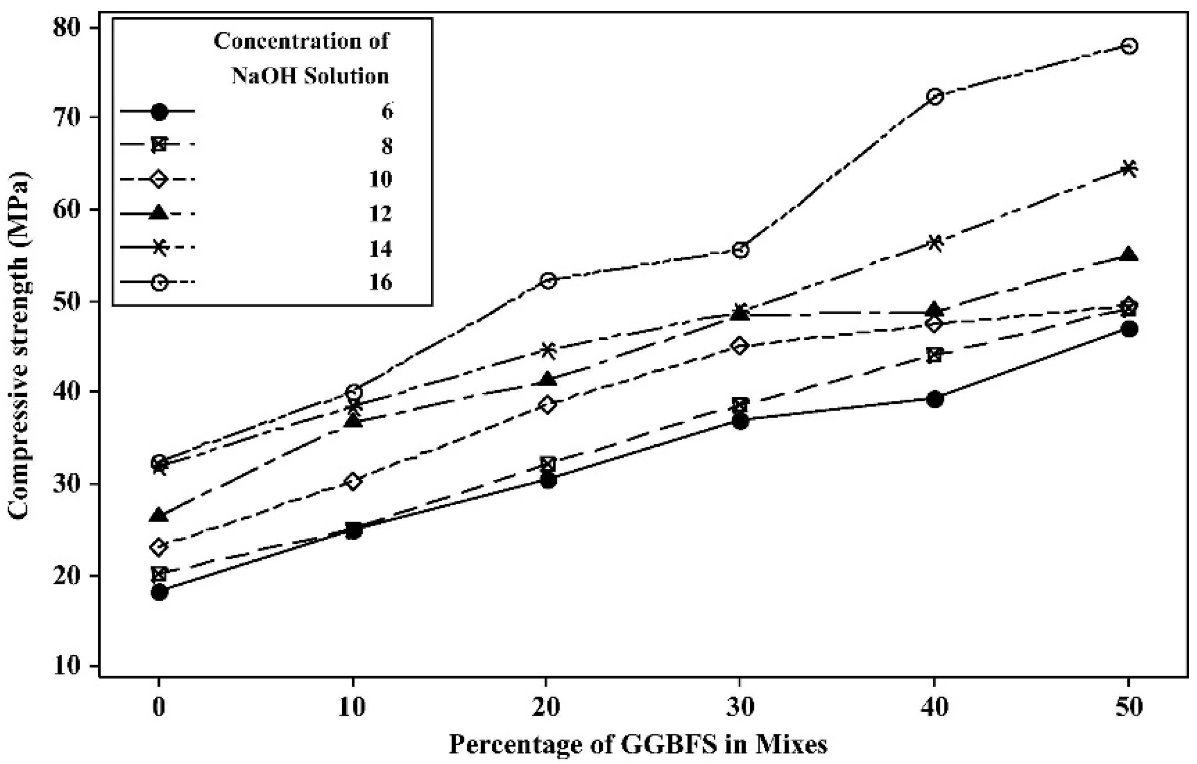
Saha and Rajasekaran [79] also attempted to improve the compressive strength properties of FA-based geopolymer paste by combining GGBFS at desired levels. From Figure 3, it was found that the compressive strength escalated with the increasing molarity of NaOH and GGBFS%; the highest 28-day compressive strength of 78 MPa was attained by the mix with 16 M NaOH and 50% GGBFS. The authors attributed this significant growth in the compressive strength to the formation of C-S-H gels in the mixture (because of the CaO content from the GGBFS) and the 3-D geopolymer network of Si-O-Al.
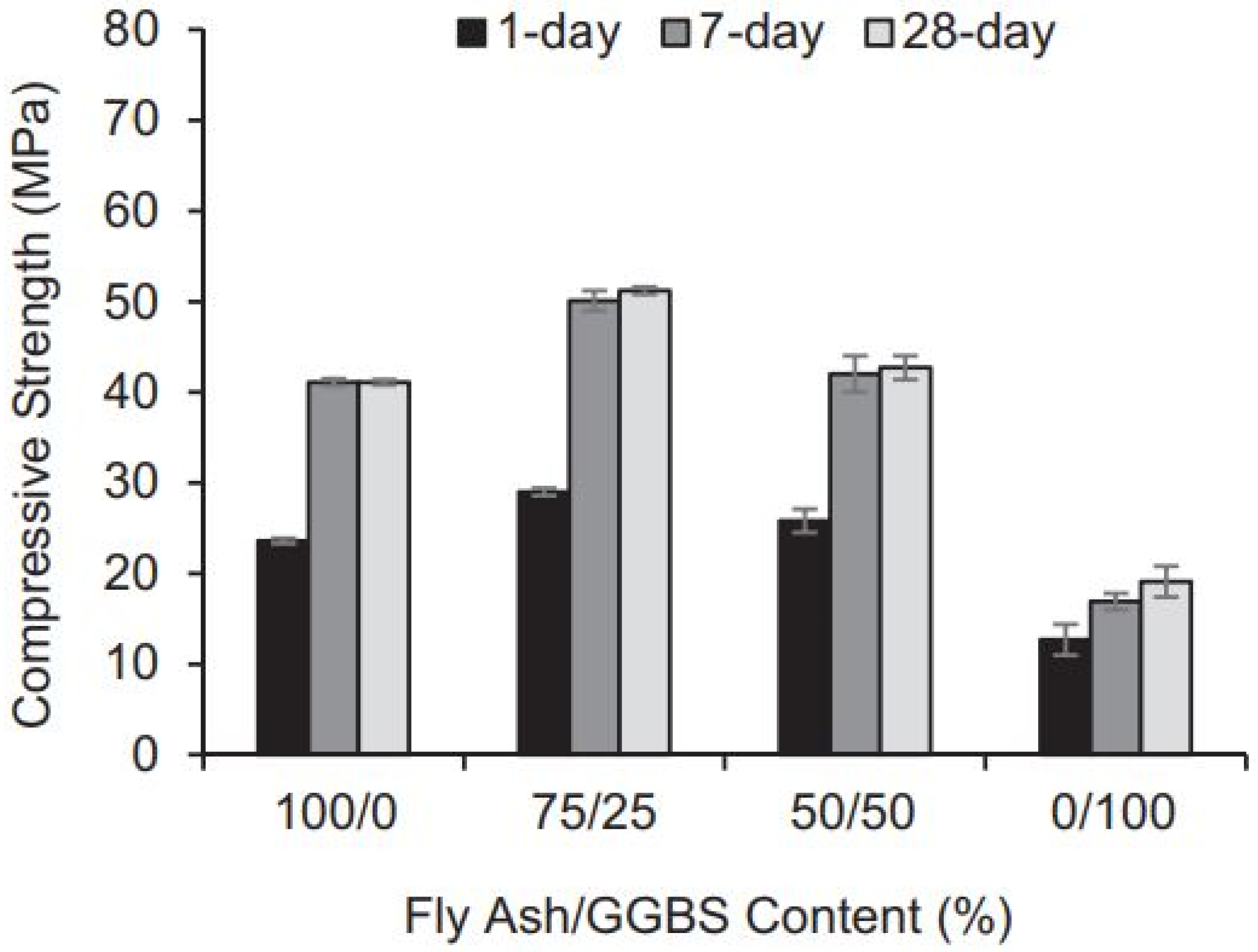
The coexistence of C-S-H gel and C-A-S-H/N-A-S-H gels have been established in a study by El-Hassan and Ismail [73], where geopolymer mortars were prepared with FA, GGBFS and desert dune sand as fine aggregates. The molarity of NaOH was fixed at 14 M, and the compressive strength results were assessed. The authors stressed that the simultaneous production of C-A-S-H/N-A-S-H gels and C-S-H gels led to the increased compressive strength of the mixes. As shown in Figure 4, the compressive strength of 100% FA mix samples was less than those containing 25% and 50% GGBFS. However, the water requirement of GGBFS particles was high, due to the presence of calcium. Therefore, the compressive strength was reduced for the mix containing 100% GGBFS and was drier than other mixes. Table 3 provides data from past works concerning the compressive strength of FA-GGBFS-based geopolymer binders.

4.3. FA-RM-Based Geopolymer Binder

The use of RM as the sole source material for the preparation of geopolymer binders is considered less successful due to its low Al2O3 and high Fe2O3 (see Table 1). For this reason, supplementary sources with a higher aluminium content, such as FA, are encouraged. Moreover, in some cases, the RM is subjected to pre-treatment with Na2O, and it was found that the compressive strength improved with this method of pre-treatment [90].
In a study by Hu et al. [12], geopolymers were manufactured using pre-treated RM and FA. It was found that the geopolymer binders with FA (50 wt.%) (i.e., by weight of the source material mix) increased in compressive strength; the highest 28-day compressive strength of 23.8 MPa was achieved. The results indicated that the Fe3+, from RM substituted Al3+ in the aluminosilicate geopolymer structure consisting of Si and Al, significantly improved the strength of the geopolymer binders.
Hu et al. [91] studied the utilization of high-volume RM to make geopolymer binders along with class C-type FA (high calcium content) and class F-type FA (low calcium content). A weight ratio of 50:50 (RM:FA) was selected for preparing mix samples under ambient conditions, using NaOH only as an activator. The results indicated that the mixes prepared with class C FA achieved better strength (15.2 MPa) than those prepared with class F FA (0.8 MPa). It was also found that the mixes with class F FA exhibited a slow reaction rate under ambient conditions compared to the class C FA-based geopolymer binders because of the presence of more active CaO content. This augmentation in strength, due to the presence of high CaO, acted as a filler by forming C-S-H gels as hydration products along with geopolymer gels (C-A-S-H/N-A-S-H). This fact is corroborated by van Deventer et al. [92], who stated that the active CaO content in the class C FA plays a significant role in the precipitation of Si and Al constituents from the source materials involved, thereby causing fast setting under ambient conditions and facilitating improved strength characteristics. Table 4 provides data from past works concerning the compressive strength of FA-RM-based geopolymer binders.

4.4. FA-IOT-Based Geopolymer Binder

Kuranchie et al. [22] studied the feasibility of using IOT as the sole source material for the preparation of geopolymer binders, where sodium silicate was included in a powdered form as an activator solution (31% of the mix by wt.). It was found that the prepared samples required high-temperature curing (80 °C) to achieve satisfactory compressive strength results (50.58 MPa) after seven days of curing time. Further, when the curing time increased to 14 or 28 days, the compressive strength declined drastically as the polymerization process reached its maximum at seven days, after which no dissolution occurred. Moreover, it was mentioned in a study by Xiaolong et al. [98] that, due to the comparatively low reactivity of IOT, its use as single source material for the preparation of geopolymers is limited. Slow hardening time, insufficient compressive strength at 28-day curing and inadequate durability characteristics make it a less preferable single aluminosilicate material for geopolymerization. Thus, the addition of supplementary aluminosilicate materials, such as FA, GGBFS and IOT, is essential to achieve improved product end properties.
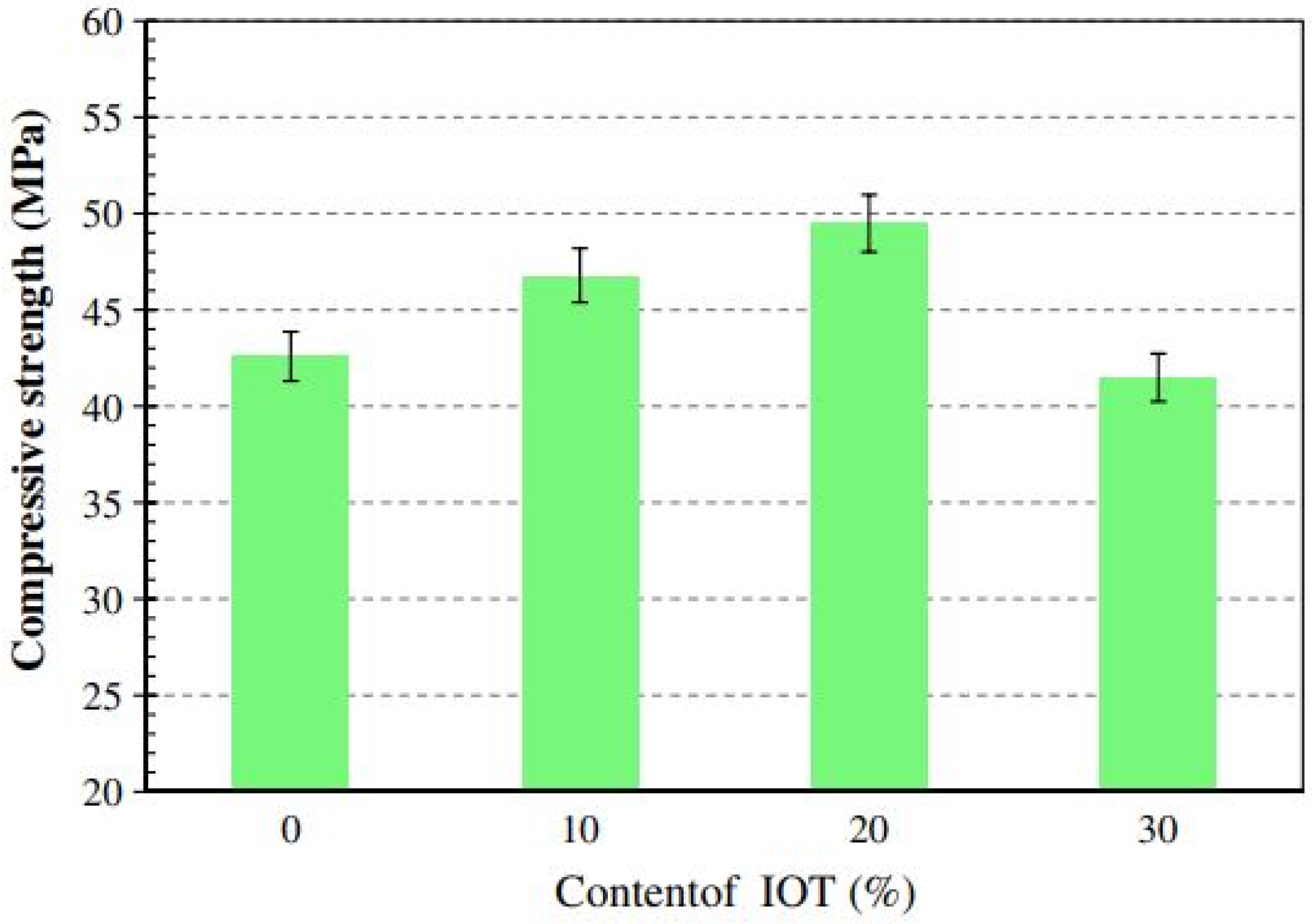
In a study by Duan et al. [99], the application of IOT and FA to prepare geopolymer pastes was investigated, and the compressive strength properties were evaluated. The FA was partially substituted by IOT, ranging from 0–30% at a 10% gap (by wt.). Figure 5 demonstrates the compressive strength results after 28 days. It can be understood that the geopolymer samples containing 20% IOT and 80% FA revealed the maximum compressive strength of 49 MPa under ambient conditions (without any need for high-temperature curing). The explanation of this strength behavior of a mix containing 20% IOT was partly attributed to the filling effect of IOT particles, which links the gaps inside the matrix, thus providing a dense microstructure and improving strength. Another reason for compressive strength increment is the presence of CaO in both IOT and FA. At 20% IOT, the reactivity of IOT was highest, and this active CaO generated sufficient C-S-H gels in the system that improved the strength of the pastes. However, when the IOT content was increased to 30%, the compressive strength declined due to the low reactivity of IOT, which reduced the rate of geopolymerization, generating fewer geopolymer gels (CA-S-H/N-A-S-H) and consequently led to decreased strength.
Within comparison to other source materials, the dissolution rate of aluminium is low in the case of IOT (under an alkaline environment) [100]. Hence, as previously mentioned, using FA or GGBFS along with IOT becomes necessary. However, due to the ease and abundance of its availability and to promote waste management, many researchers have also investigated the use of high-volume IOT as fine and coarse aggregates [101,102,103,104] for concrete production, and the results are promising.

4.5. FCA -FA-Based Geopolymer Binder

FCA is one of the contemporary source materials used in the preparation of geopolymer binders, along with FA. Saha et al. [105] examined the feasibility of FCA- and FA-based geopolymer concrete, using 13 M NaOH and Na2SiO3 solution as alkali activators. The natural coarse aggregates were replaced by recycled coarse aggregates (RCA), up to 50%, and the compressive strength of the samples was evaluated. The results revealed that effective geopolymerization occurred due to a combination of FCA and FA to achieve adequate strength. The authors essentially recommended a 20% replacement of RCA to be used in manufacturing concrete for sustainable infrastructure solutions. In another study by Mishra et al. [24,48,106], several geopolymer mixes were prepared by varying FA mix proportions from 20% to 80% in the source mix. The alkaline solutions of sodium hydroxide and sodium silicate were used to activate these sources. It was observed that a mixture containing FCA and FA in a 60:40 ratio could be best suited for geopolymerization, resulting in a 28-day compressive strength of 29.3 MPa under ambient curing conditions.

4.6. FA-MK-Based Geopolymer Binder

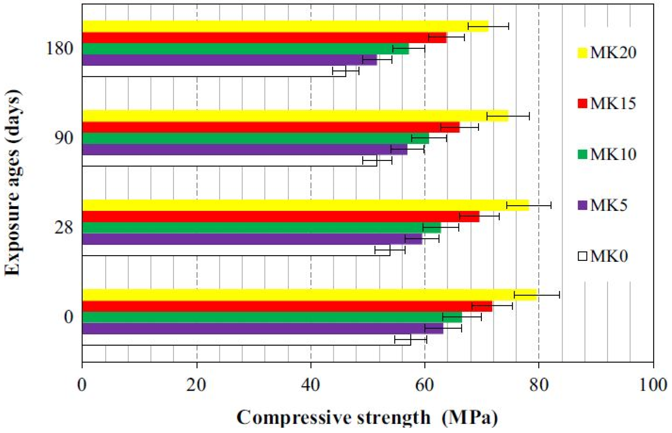
Duan et al. studied the strength development of FA-based geopolymer paste by including MK with replacement percentages (0%, 5%, 10%, 15%, 20%) under ambient curing conditions for 28 days [107]. Subsequently, the specimens were exposed to 5% sodium sulfate solution (Na2SO4) for 28, 90 and 180 days. The compressive strength of the cubic specimens (100 × 100 × 100) mm3 was measured under loading rates of 0.6 MPa/s. The results illustrated in Figure 6 reveal strength loss after sodium sulfate solution exposure regardless of the replacement level of fly ash by metakaolin. However, the geopolymer gains strength by increasing the replacement level of metakaolin from 5% to 20%.
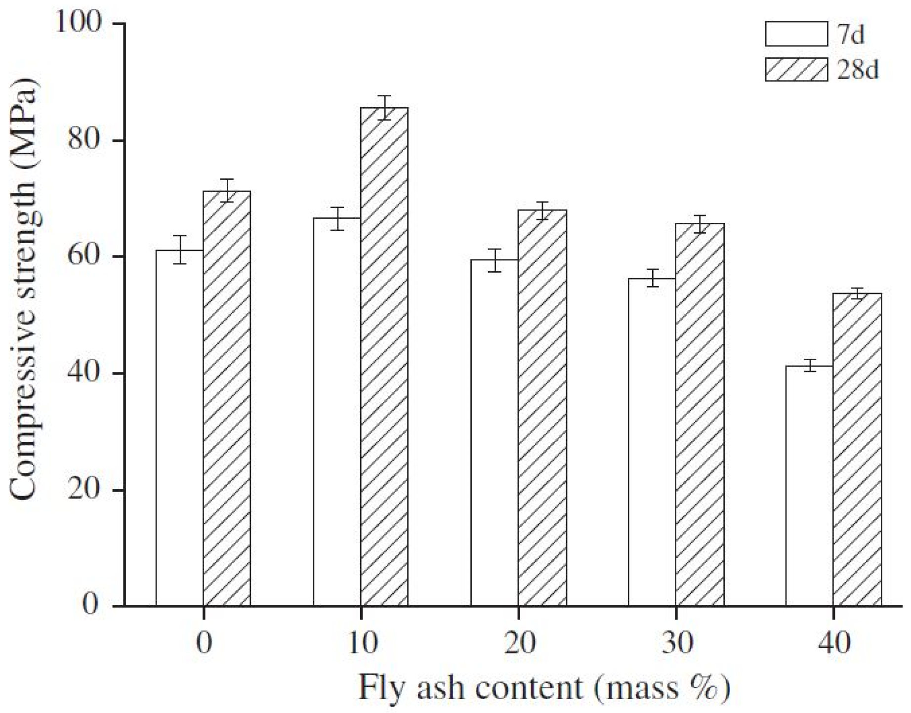
Another study, by Zhang et al., observed a 15% increase in the compressive strength of MK-based geopolymer with 10% FA replacement, while recording a 5%, 8% and 22% decrease with 20%, 30% and 40% replacement with FA, as depicted in Figure 7 [108]. The authors proclaimed the gel content and extent/rate of reaction between the binder mix and the alkaline activator to be a prime factor in compressive strength development. Contact between the activator solution and the mix binder particles decreased with a constant liquid/solid ratio of 0.6 and higher fly ash replacement levels, resulting in a longer initial reaction time.

4.7. FA-SF-Based Geopolymer Binder

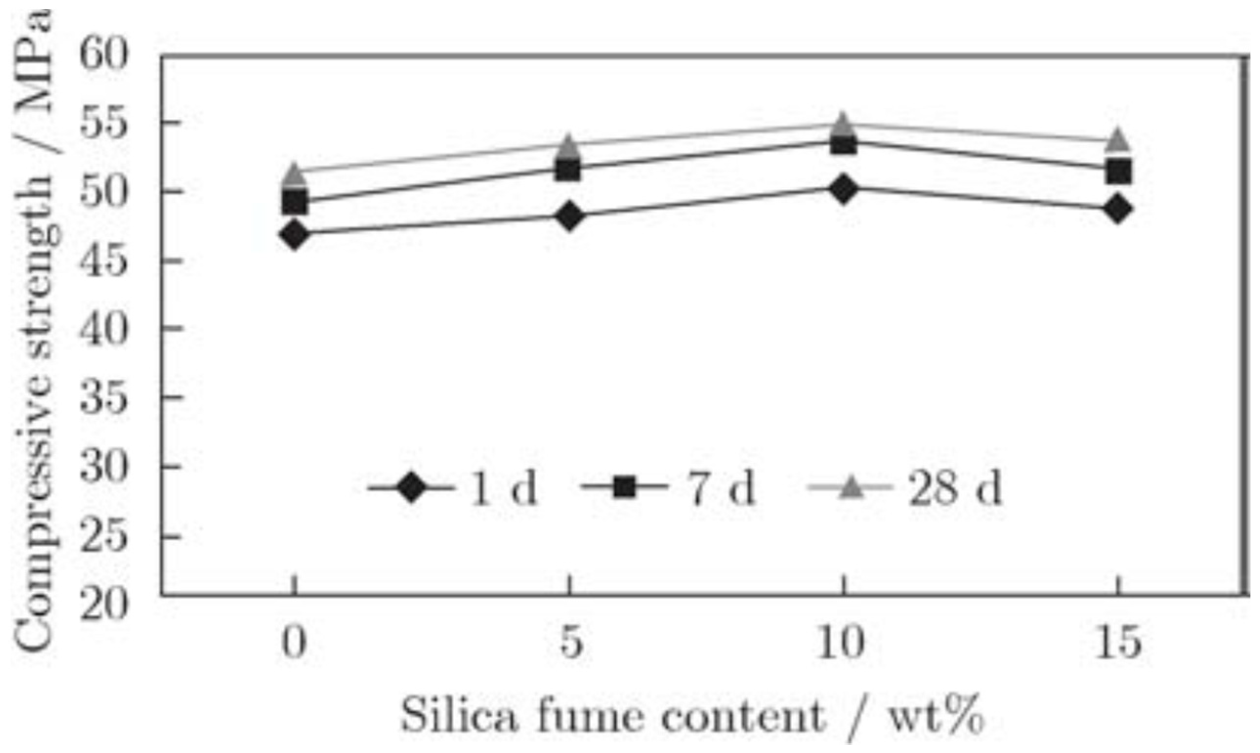
Adequate replacement of SF in FA-based self-compacting geopolymer concrete was perceived by Memon et al., with substitution levels of 0, 5, 10, and 15 wt.% [109]. Parameters such as (w/b) ratio and binder content were kept constant, at 0.33 and 400 kg/m3. The molds were initially cured at 70 °C for two days, and later cured at ambient temperature to acquire a maximum 28-day compressive strength of 55.02 MPa (6.9%), with 10% replacement of SF, as displayed in Figure 8. The obtained strength was inferred due to the pozzolanic reactivity and pore-filling capability of SF, resulting in a denser microstructure. Moreover, the addition of SF also provides additional SiO2, which is beneficial during geopolymerization reactions to form a geopolymer matrix with a denser gel structure [110].

5. Part II: Review of Microstructural Properties

This section discusses the microstructural properties of geopolymer binder systems. The properties such as X-ray Diffraction (XRD), Scanning Electron Microscope (SEM), and Fourier-Transform Infrared spectroscopy (FTIR) are reviewed in light of the wastes analyzed in this study. In general, the microstructure properties vary according to the source materials used and, therefore, heavily influences the final compressive strength development of the geopolymer binders.

5.1. XRD

5.1.1. FA-Based Geopolymer Binder

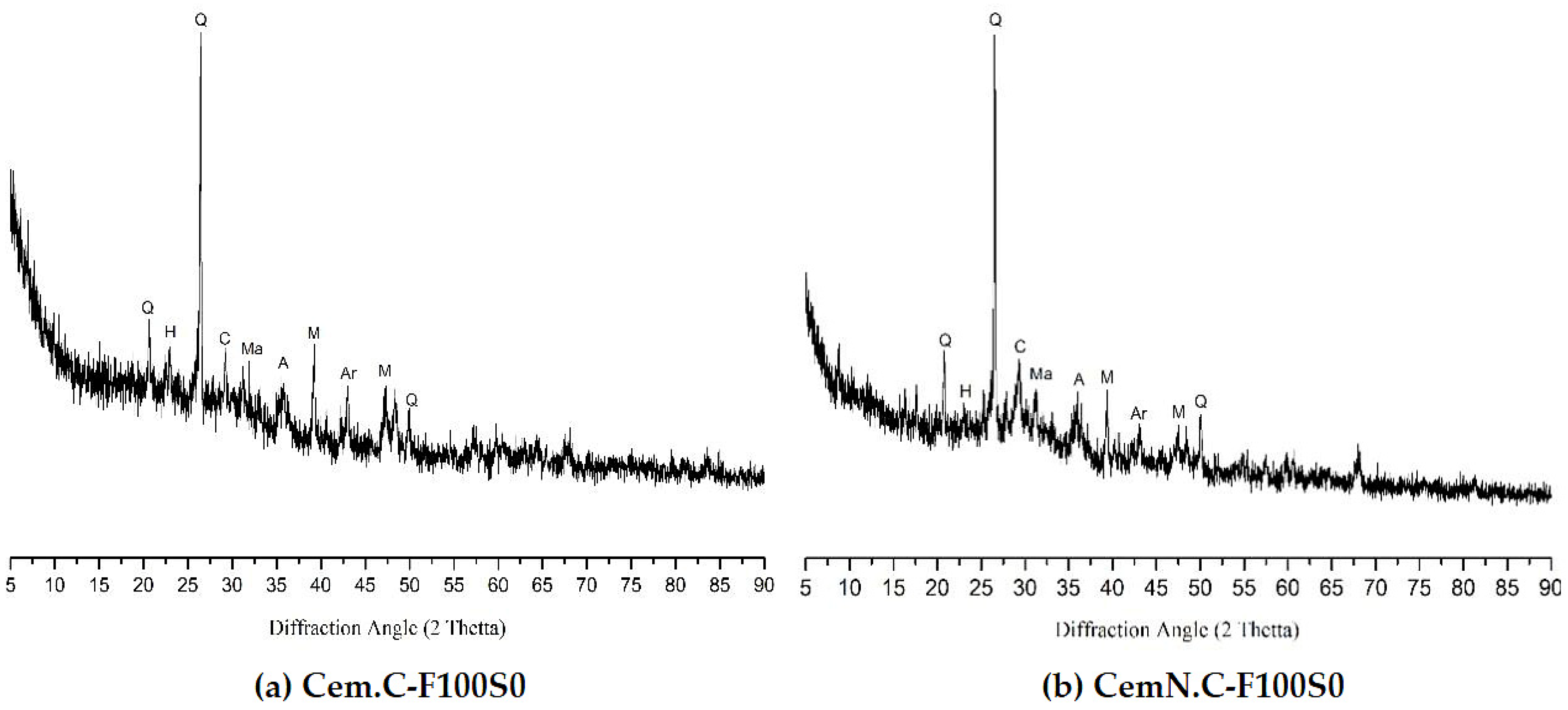
Sasui et al. [78] employed NaOH (Cem. C) and NaOH+Na2SiO3 (CemN.C) alkaline solutions in 100% FA-based geopolymer mortars. XRD patterns of the mixture specimens indicate the different crystalline phases and the difference in the crystallinity percentage of FA upon activation by Cem. C (24.23%) and CemN.C (19.72%). The intensity of hydrosodalite (formation due to high SiO4 and AlO4 in contrast with CaO) was higher in Cem. C, resulting in lower strength than CemN.C due to the amorphous silicate supplied from Na2SiO3. Calcite peaks around 2θ (28°), in both compositions, indicated the availability of unreacted Ca, as it was not associated with C-S-H development. Moreover, the formation of a low-intensity hump between 2 (18°–35°), in Figure 9a, and high-intensity hump between 2θ (23°–38°), in Figure 9b, could be associated with the formation of an amorphous compound in gel due to the presence of amorphous silica.
In another study, Tho-In et al. [71] investigated the XRD patterns of the 7-day oven-cured geopolymer paste (100% FA), as illustrated in Figure 10. The hardened paste exhibited a glassy matrix, which can be established through the broad hump in Section 25° < 2θ < 35° and the low-intensity peaks of calcite (CaCO3) and quartz (SiO2) signifies their poor crystallinity behavior; as a result, there was a significant degree of geopolymerization.
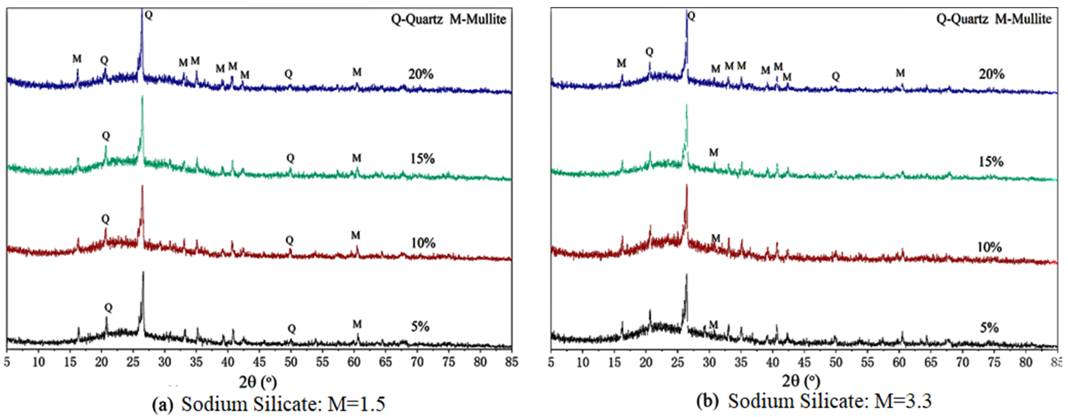
Activation of 100% FA-based geopolymer mortar through NaOH and varying modulus of Na2SiO3 (1.5, 3.3) was undertaken by Lv et al. [111] to comprehend the consequential effects on the strength and microstructure of the resulting geopolymer mortar. Figure 11 illustrates the XRD data of the ambient cured mortar with a notifiable hump between 2θ (20°−35°), indicating primary hydration gel products (N-A-S-H) in the amorphous phase, generated by the geopolymerization reaction in the system. As the dosage of Na2SiO3 increased in Figure 11a, minor changes in the diffraction peaks of the spectrum can be spotted around 2θ (21°), as the diffraction peaks of quartz and mullite decrease as the dosage increases, proving that increased dosage and low modulus of Na2SiO3 can contribute to adequate activation of fly ash, leading towards suitable strength development. Figure 11b does not indicate any results in the reaction products, in contrast with Figure 11a, as the rise of SiO2 content and decrease of Na2O in Figure 11b lead to insufficient alkali content in the system. No significant development in the diffraction peaks of the spectrum can be witnessed as the sodium silicate dosage increases.

5.1.2. FA-GGBFS-Based Geopolymer Binder

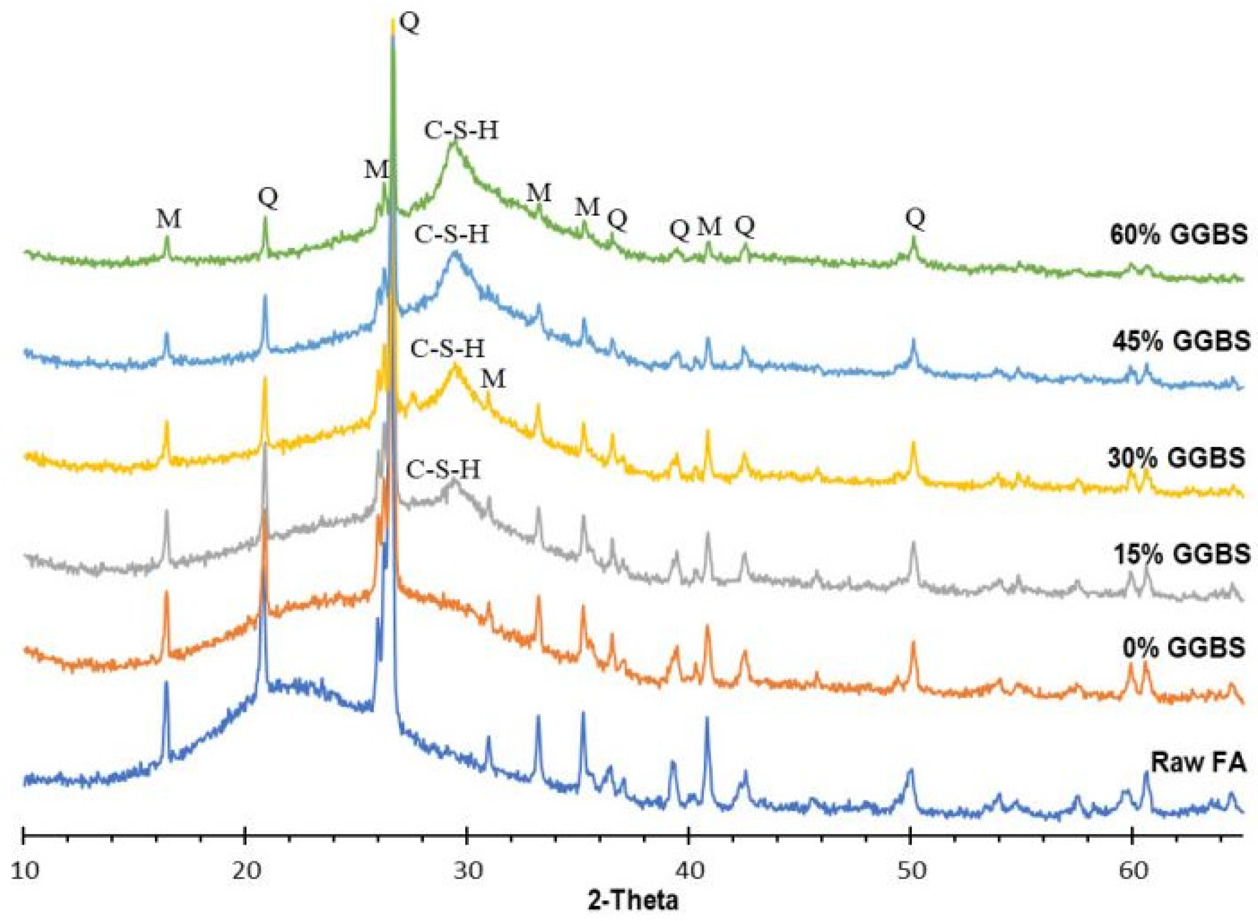
In a study by Saludung et al. [112], the XRD test was carried out to understand the microstructure evolution of the FA-GGBFS geopolymer binder system. The GGBFS was replaced from 0–60% by wt. of the FA at a 15% interval. Figure 12 presents the XRD test results of the raw FA and the geopolymer pastes, with varying quantities of GGBFS. It can be observed that a broad, amorphous hump is seen at 15–38° (2-θ) for FA, which suggests its high reactivity. For the pastes containing 0% GGBFS, a slight shift is noticed in the amorphous hump (15–40°) that confirms the development of geopolymer gels. The peaks of mullite (M) and quartz (Q) found in the case of raw FA alone are also seen even after exposure to an alkali solution and the inclusion of GGBFS. However, when GGBFS was introduced into the system (15–60%), the overall XRD pattern of the geopolymer pastes remained unchanged. At the same time, a new diffraction peak was formed around 30° (2θ) as a result of the generation of C-S-H gel. Moreover, the intensity of this peak increased with the increase in GGBFS inclusion in the paste. It is also important to note that the samples with 0% GGBFS exhibited no peak conforming to C-S-H gels as FA does not contain a sufficient quantity of active calcium in it, which can participate in geopolymerization.
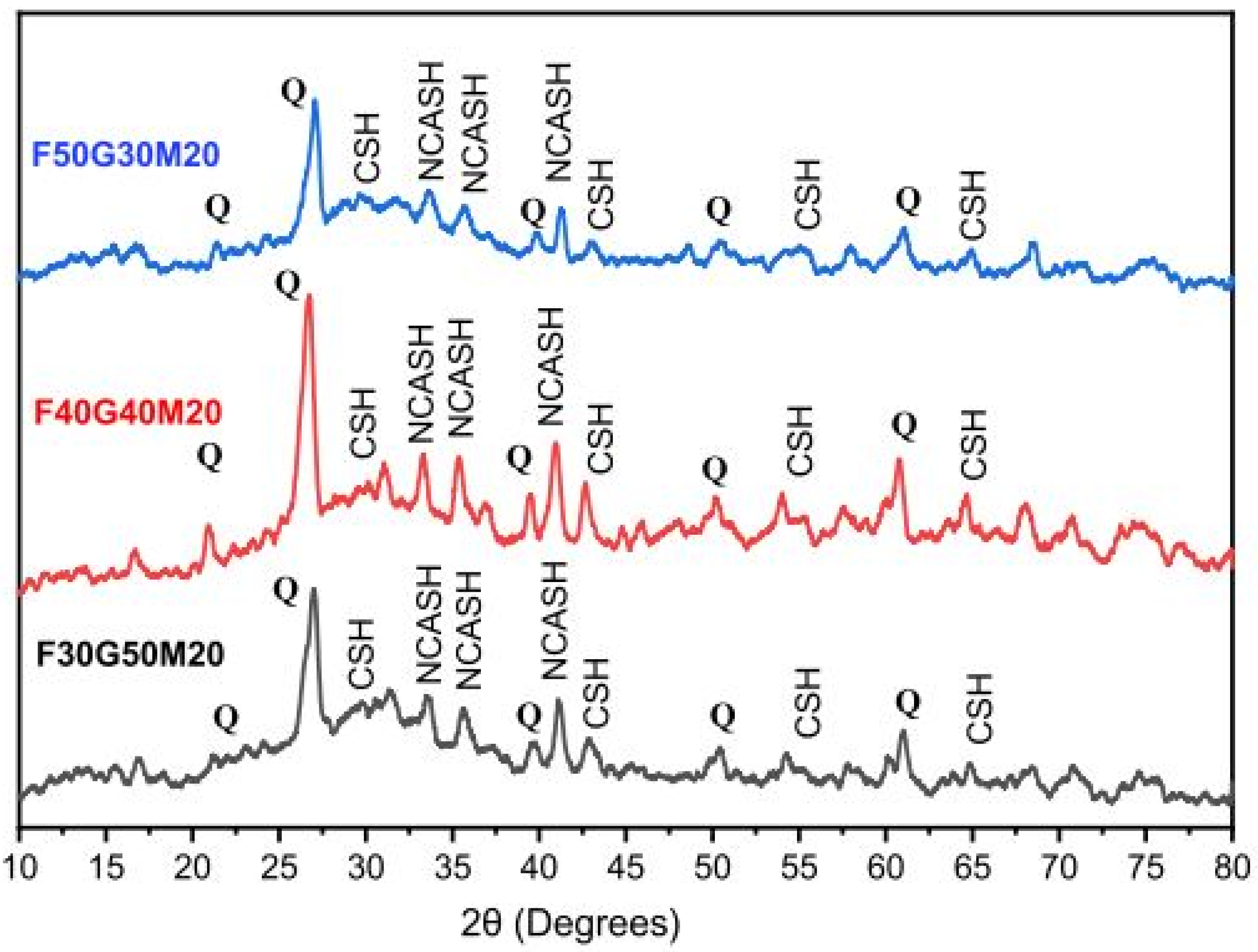
Similarly, Kamath et al. [113] studied the XRD patterns of the geopolymer binder system made up of FA and GGBFS, with the addition of metakaolin (5%, 10%, 20% by weight). At seven days of ambient curing, the FA-GGBFS mixes containing 20% metakaolin attained the highest compressive strengths. The corresponding XRD pattern of the mixtures is presented in Figure 13. From the figure, it is identified that the peaks of SiO2, i.e., quartz (Q), dominate the spectrum in the case of all the geopolymer mix samples. However, the intensity of these peaks reduced when the quantity of GGBFS increased in the binder system. This reduction in the intensity is partly attributed to the fineness of metakaolin and the increased CaO contents, for which the constituents of SiO2 underwent full alkaline activation to form various aluminosilicate gels that govern the strength development. The hump around 20–40° (2θ) exhibits the formation of gels such as C-S-H, C-A-S-H and N, C-A-S-H in all the mixes. This co-existence of the gels is also described in [114,115], to the higher strength gain of the geopolymer binders.

5.1.3. FA-RM-Based Geopolymer Binder

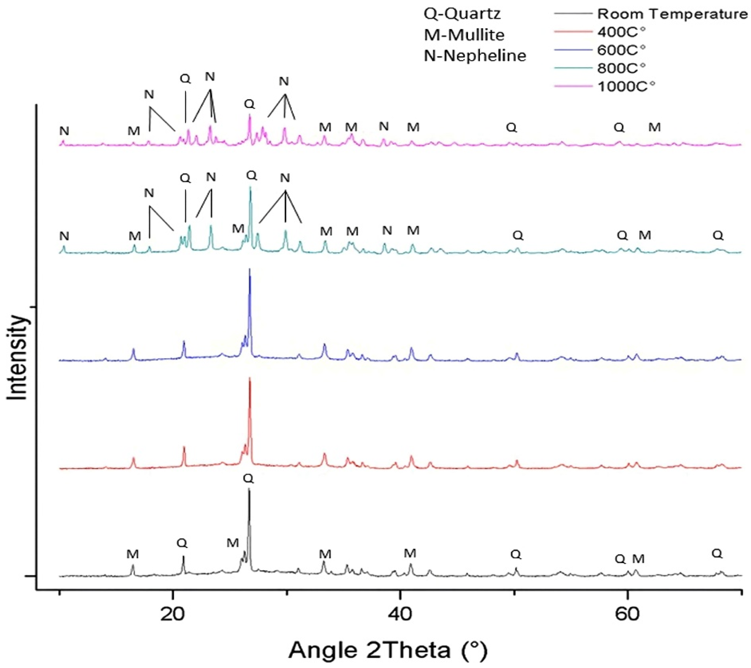
Yang et al. [116] examined the changes in the XRD patterns of RM-FA-based geopolymer binders, which were exposed to room and elevated temperatures (400–1000 °C), as shown in Figure 14. It is observed that each XRD pattern exhibits a broad hump between 20°–40° (2θ), which indicates its amorphous characteristics. The FA selected for this experimentation is reported to consist of mullite and quartz, also found in all of the RM-FA geopolymer samples. The figure illustrates that until 800 °C, there is no significant change in the XRD patterns. A new mineral compound–Nepheline, is found in the XRD patterns of the samples cured at 800 °C and 1000 °C, and this has been established in [117]. However, as reported, the formation of Nepheline caused serious volume expansion that resulted in stress and cracks formation. Eventually, the geopolymer matrix collapsed, leading to rapid strength loss when cured at 800 °C or above.
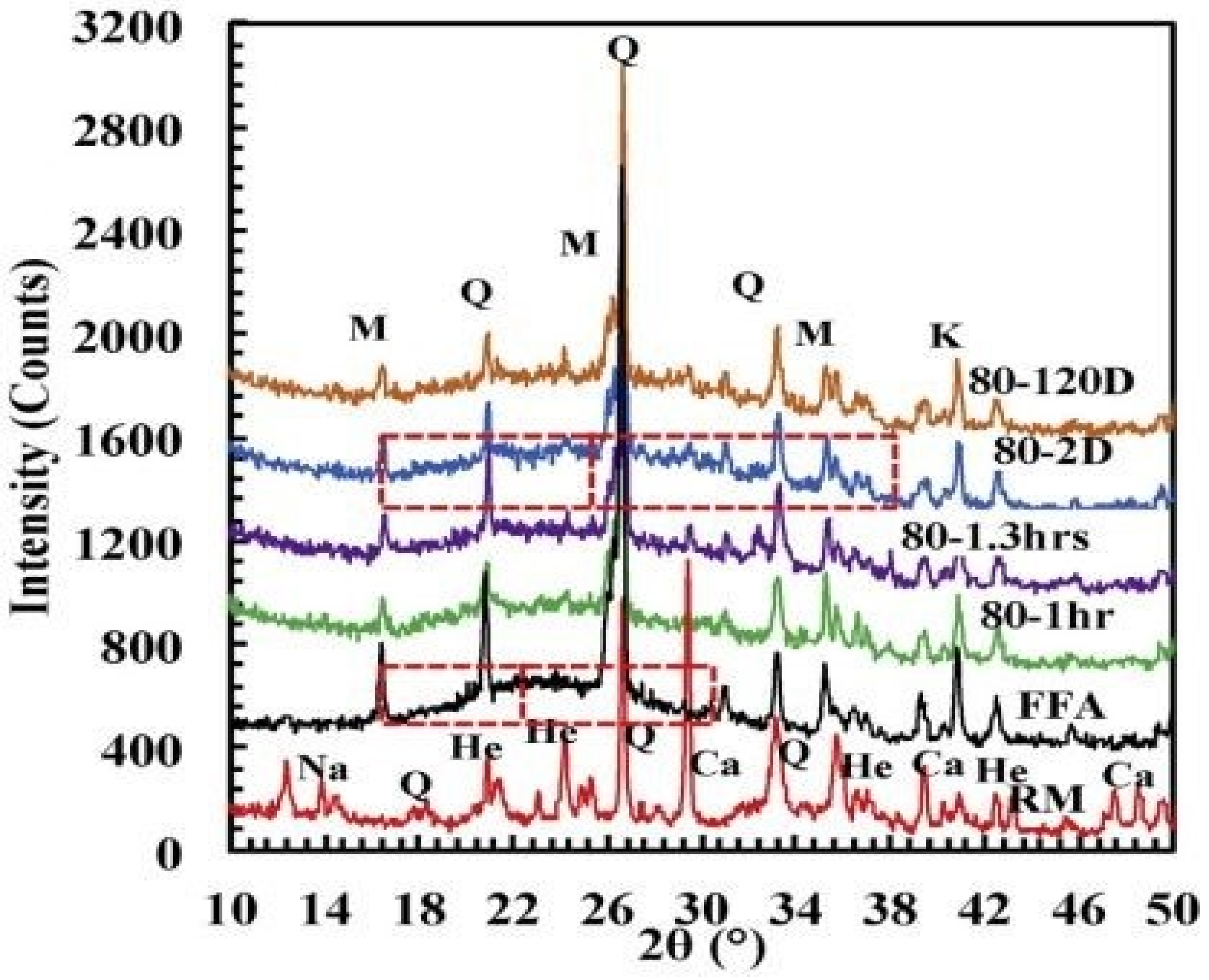
Zhang et al. [118] analyzed the microstructural changes, with the help of XRD patterns of the geopolymer binder made with RM, and class F fly ash (FFA) cured at 80 °C for varying time periods (1 h, 2 days, and 120 days). Primarily, the binder consisted of 80% FFA. Figure 15 presents the XRD patterns of geopolymer samples and raw materials–RM, FFA. It is observed that the amorphous behavior of FFA is characterized by the hump between 16–30° (2 θ) in its XRD pattern. However, after two days of curing, it is found that there is a shift in this hump to 16°–38° (2 θ). The individual centers are distinguished on the XRD patterns, as shown in Figure 15. The generation of reactive geopolymer gels is responsible for this shift in the hump, confirmed in previous findings [119].

5.1.4. FA-IOT-Based Geopolymer Binder

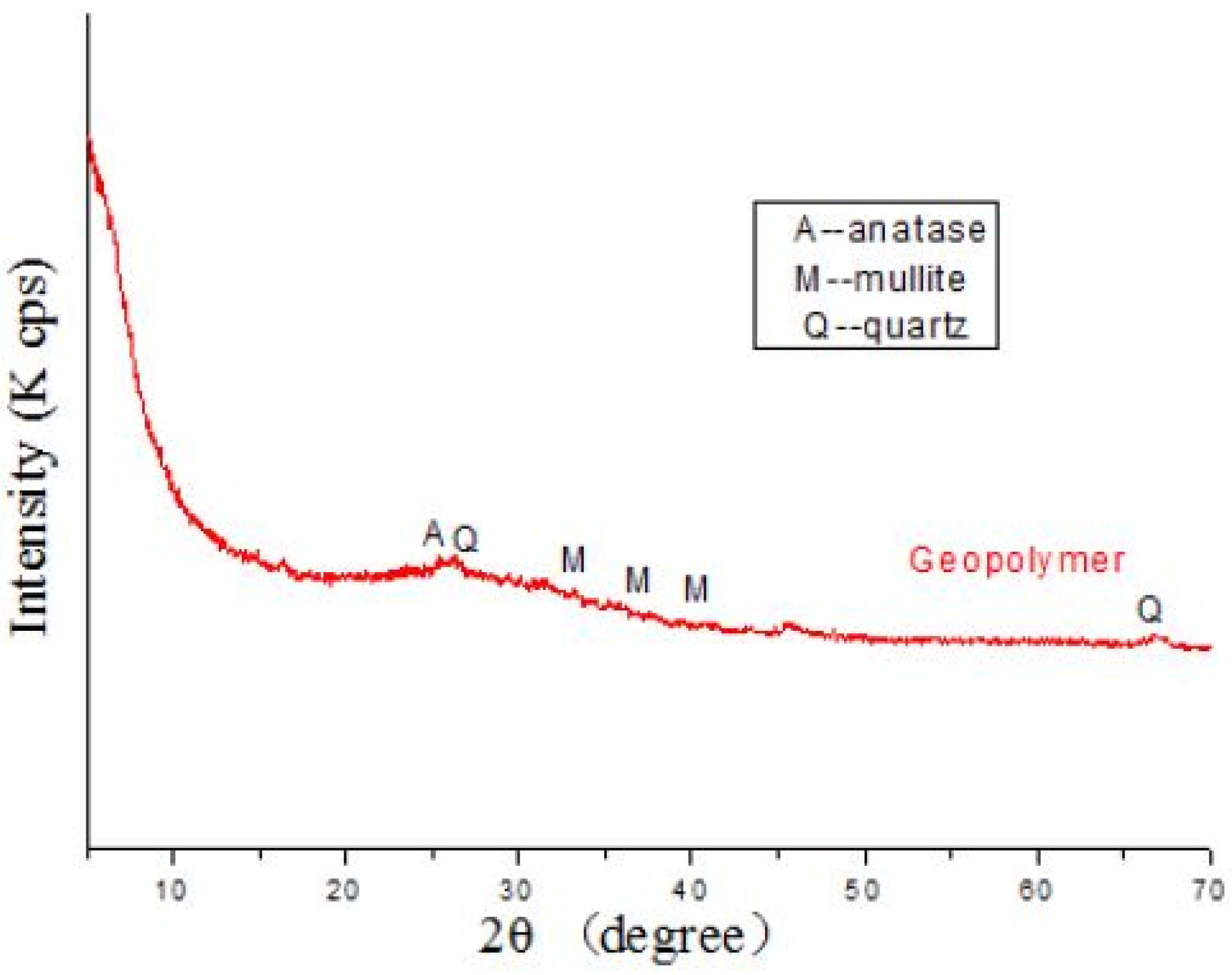
In a study by Duan et al. [120], the geopolymer binders were prepared with IOT and fly ash, activated by a combination of 10 M NaOH and Na2SiO3 solution, where IOT replaced 30% (by wt.) in the mix. The microstructure phase compositions of the resulting geopolymer were characterized using XRD analysis. The XRD pattern is shown in Figure 16. It is reported that, following the subsequent geopolymerization, the mineral phases such as anatase, calcite, mullite and quartz, which existed in the raw materials (IOT and FA) are also present in the XRD pattern of the resulted geopolymer samples. However, the sharp intensity of their peaks is transformed into broad peaks (in geopolymer), which signifies the dissolution of particles of IOT and FA under an alkaline environment, which leads to the formation of an amorphous aluminosilicate structure during the reaction process.
XRD patterns of IOT as a single source material for geopolymerization have previously been studied in Kuranchie et al. [22], where it is confirmed that partial dissolution of the constituent minerals present in IOT occurs to form geopolymer gels that enhance the strength of the samples.
However, the studies related to the XRD characterization of geopolymer binders made with IOT-FA are very limited. Therefore, further studies relating to XRD analysis of geopolymer binders made with IOT-FA are required in order to examine and understand the microstructure changes of the resulting binder systems.

5.1.5. FCA-FA-Based Geopolymer Binder

Mishra et al. studied the XRD patterns of geopolymer samples formed by incorporating 60% FCA and 40% FA in the source material mix [24,48,106]. The XRD pattern revealed the presence of peaks of mineral compounds, with the chemical formula KAlSi3O8, that belong to the K-feldspar group, quartz, forsterite (magnesium silicate), and donathite. The change in the chemical composition of the source material mix with the inclusion of FCA led to the formation of some new mineral compounds. It is also evident that quartz from FA, forsterite (magnesium silicate), donathite from FCA remained unreacted during the geopolymerization process. The MgO from FCA could have led to the formation of Mg-bearing gel phases, namely N-M-A-S-H or M-A-S-H, but no such peaks were detected due to their amorphous character.

5.1.6. FA-MK-Based Geopolymer Binder

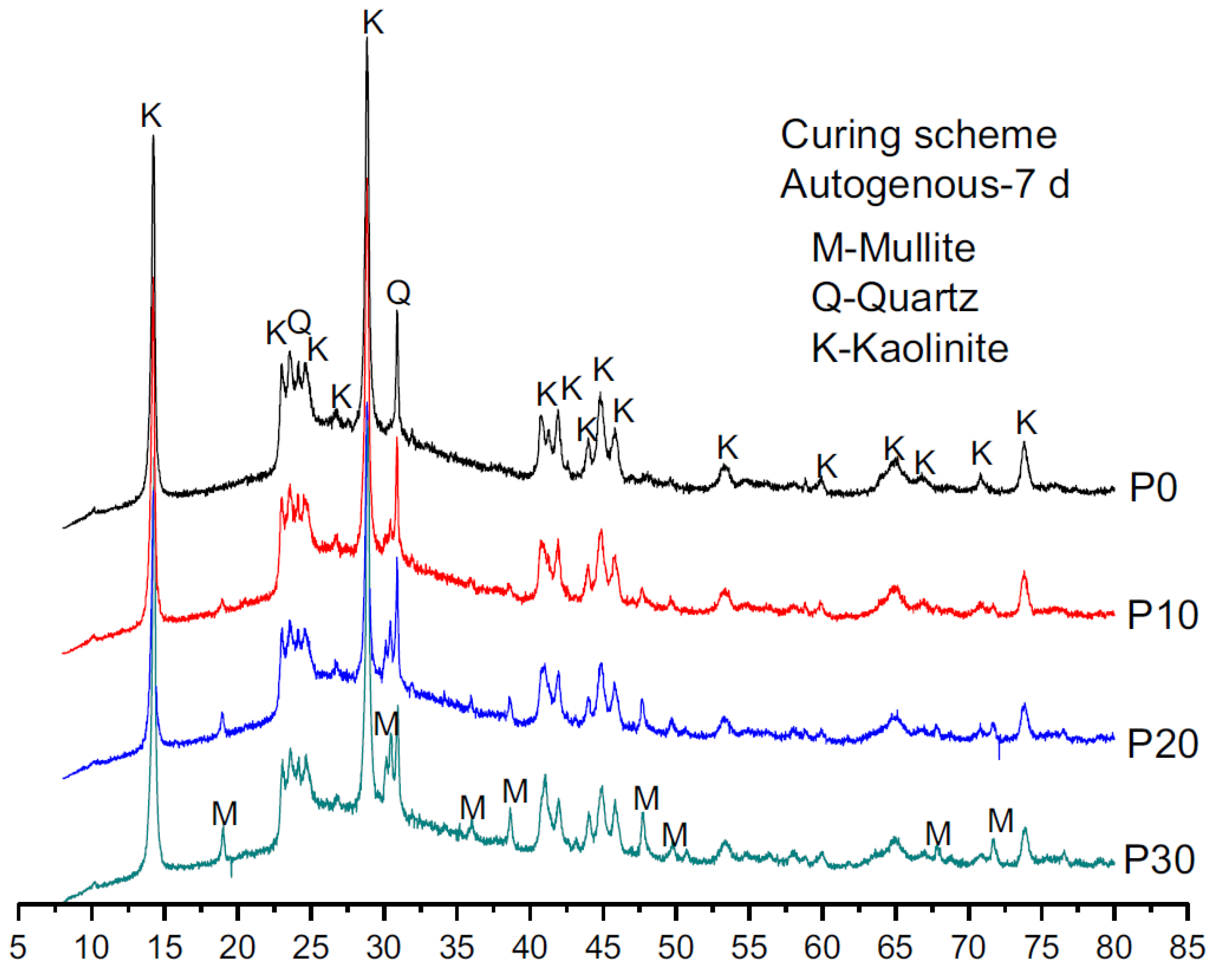
Yang et al. studied the XRD patterns of ambient cured MK-based geopolymer with varying FA replacements (0, 10, 20, 30 wt.%) [121]. The authors analyzed the XRD patterns of the source materials. They deduced the presence of broad aluminosilicate humps at divergent positions owing to the physical characteristics of the amorphous elements available in FA (20–35°) 2θ and MK (22–30°) 2θ. Figure 17 displays the availability of Mullite, Quartz and Kaolinite phases, from 22–40°, 2θ in the geopolymer specimens at an elevated angle, corresponding to the evolution of tangled aluminosilicates binder gel.

5.1.7. FA-SF-Based Geopolymer Binder

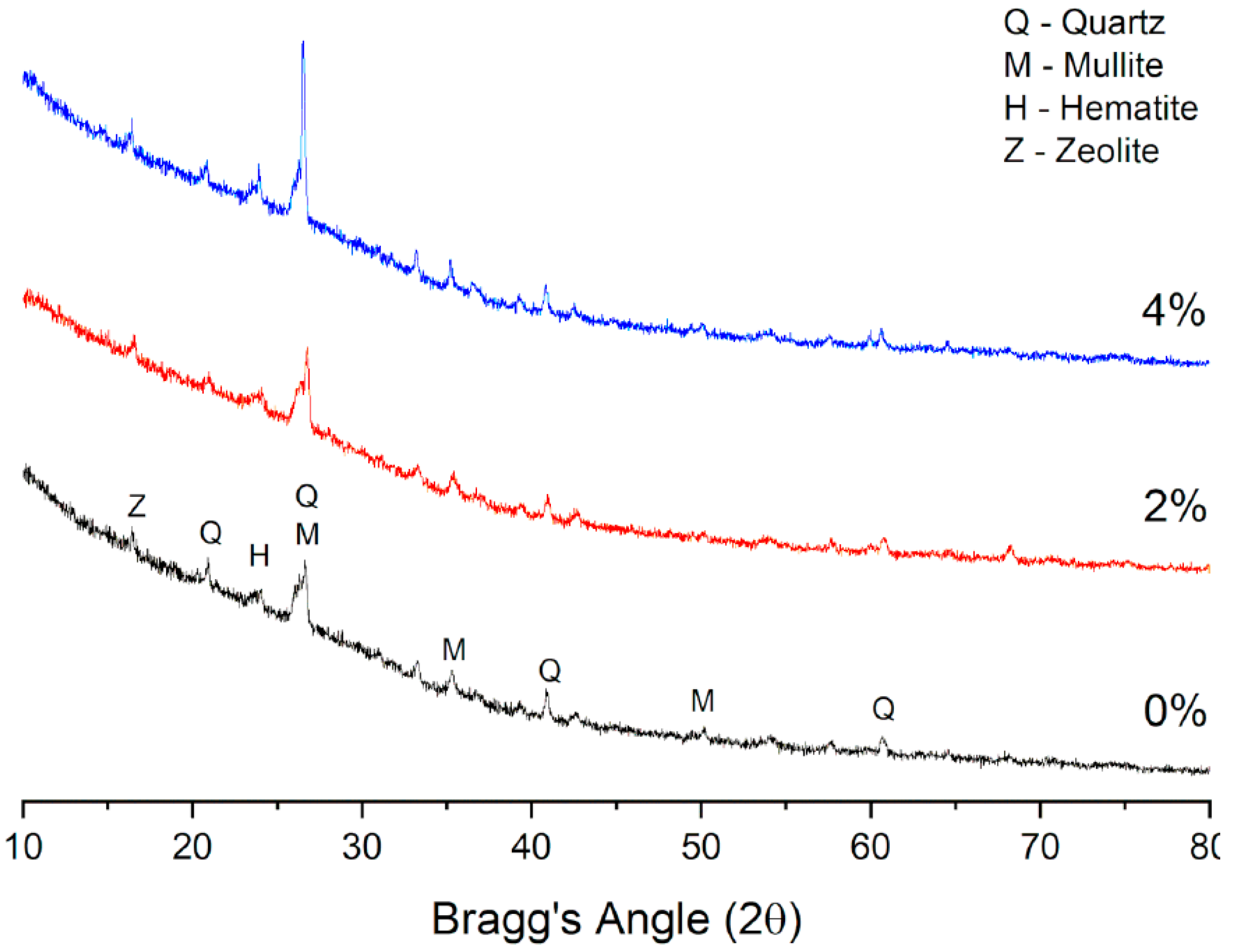
The microstructure of SF- and FA-based geopolymer has been evaluated by Li et al. [122] through XRD analysis. The geopolymer was cured in ambient conditions with a fixed binder/liquid ratio (2.5) and varying SF inclusions (0, 2, 4 wt.%). Figure 18 illustrates the primary crystalline peaks in the geopolymer with quartz, mullite and lower hematite phases originating from the included FA. The appearance of zeolite was deduced as the secondary reaction product originating during geopolymerization. At 2θ (26.5°), the intensity of mullite and quartz was high, mostly with 4% SF inclusion. The authors concluded that the high intensity resulted from the lower dissolution of aluminosilicate and the progression of chemical reactions to form the geopolymer network. Table 5 shows the XRD peaks obtained from different geopolymer binder compositions involving FA.

5.2. SEM

5.2.1. FA-Based Geopolymer Binder

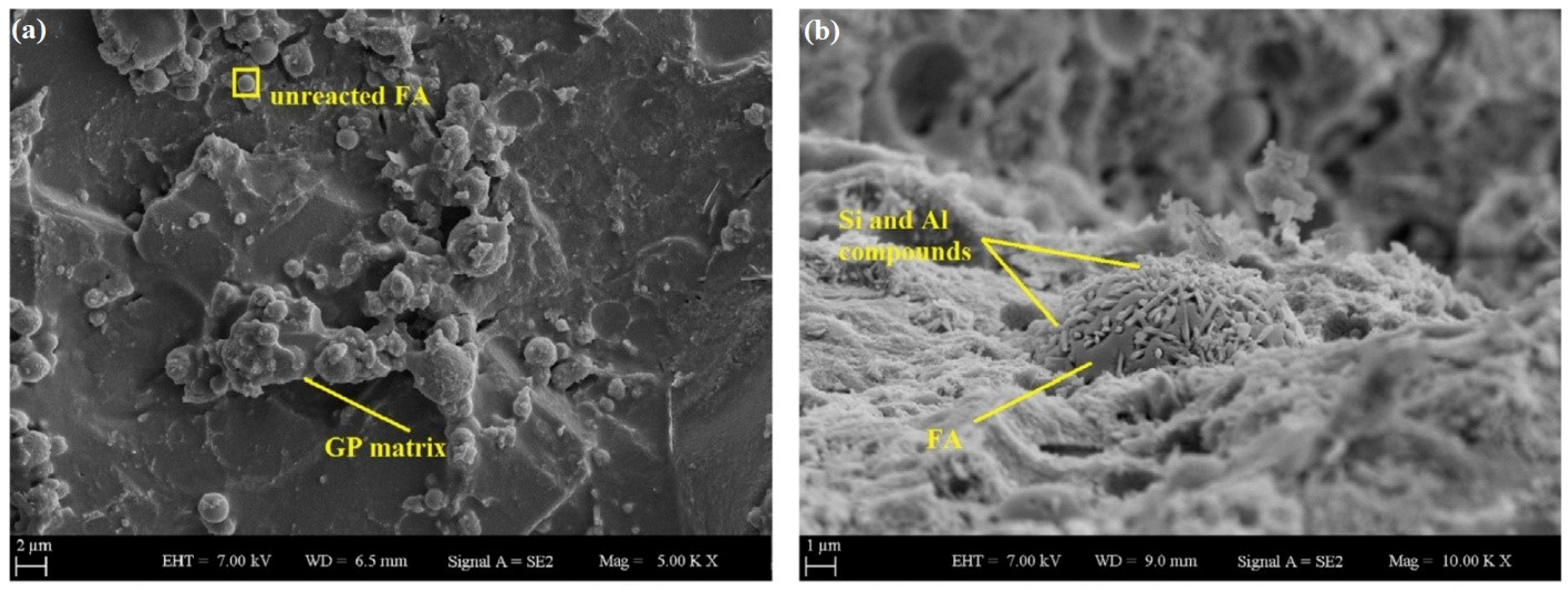
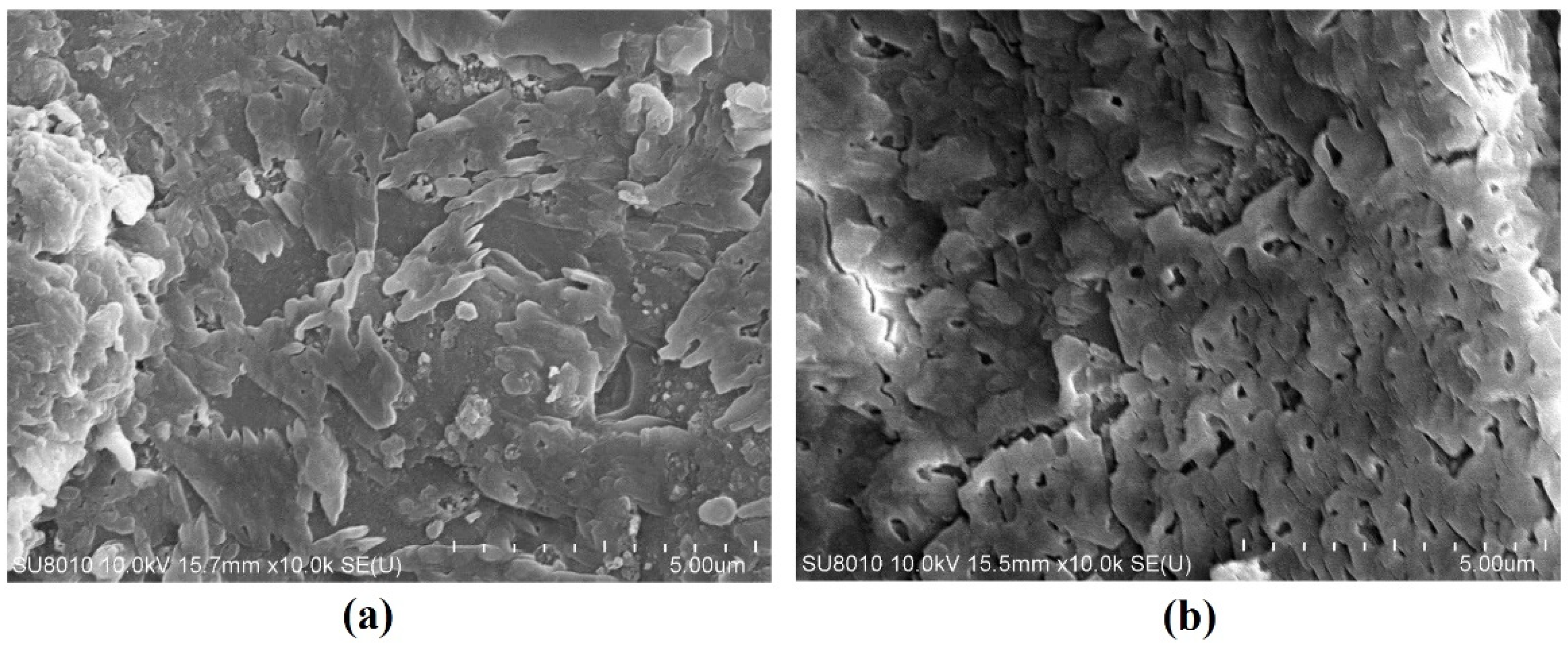
SEM micrographs of 100% FA-based geopolymer mortars, developed by Al-mashhadani et al. [30], are illustrated in Figure 19a. From the figure, it is revealed that there existed some unreacted FA over the geopolymer matrix, which correlates positively with the strength behavior of the composite under compression. The unreacted FA does not behave as a reinforcement material, but instead strengthens the matrix with age due to the bonding strength offered by the complex reaction between the surface of the particles. A micrograph with a magnification of 10,000, in Figure 19b, demonstrates a fly ash particulate reacting with prism-shaped pillars, primarily composed of Si and Al constituents, implying that Si-O and Al-O bonds are the primary chemical reactions that produce this binder. Alternatively, these prism-shaped pillars could be identified as an Al-tobermorite phase whose formation was mostly facilitated by abundant Al constituents from sand [124].
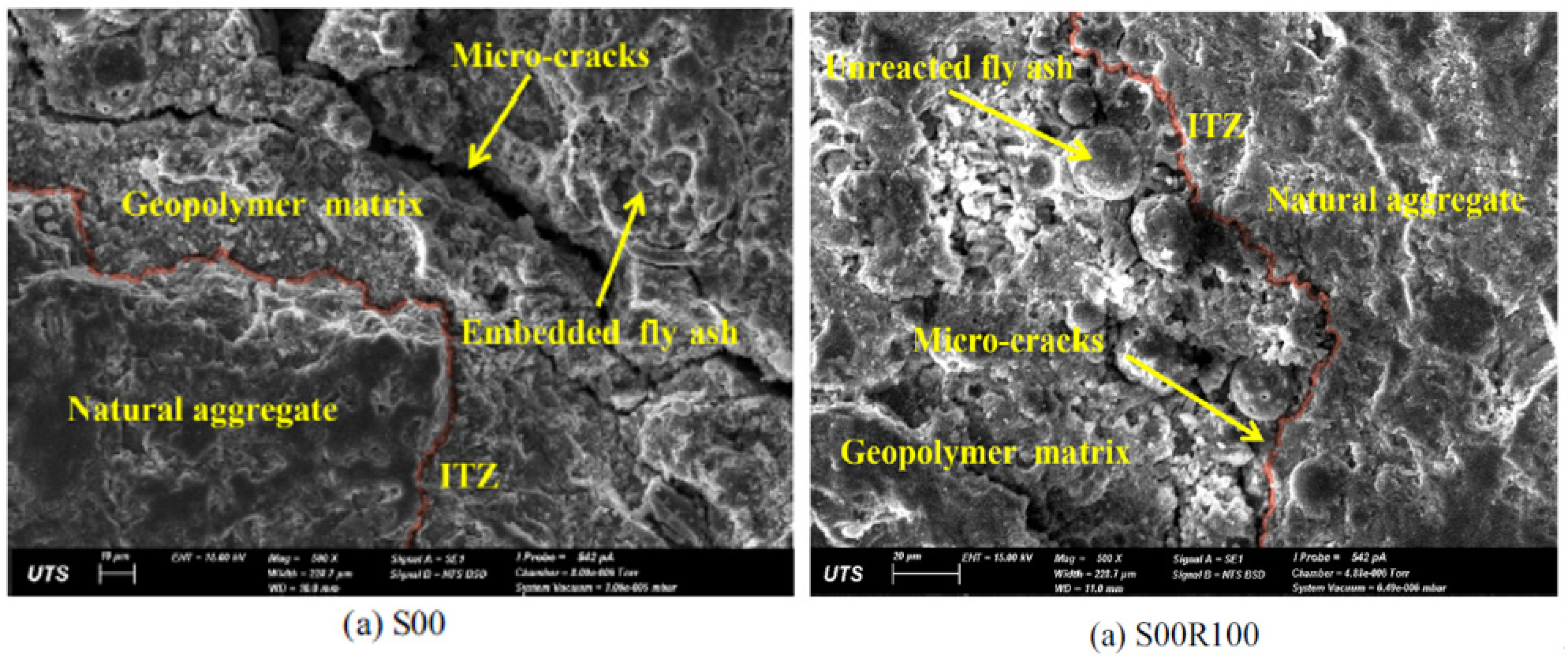
The scanning electron microscopic characterization of 100% FA-based geopolymer concrete was conducted by Hu et al. [75], as depicted in Figure 20, to observe the morphology, effect of natural and recycled aggregate on the resulting microstructure and interfacial transition zone (ITZ) of the geopolymer matrix. Distinctive differences can be witnessed in the microstructure of the geopolymer specimens: S00 (containing natural aggregates) and S00R00 (containing recycled aggregates). S00 and S00R00 revealed the formation of multiple porosities and a non-uniform structure, accompanied by evident cracks, as the geopolymer matrix had numerous defects and was not dense, owing to the absence of a secondary binder which could lead the weak point to change from the geopolymer matrix to the ITZ between the geopolymer matrix and aggregates.
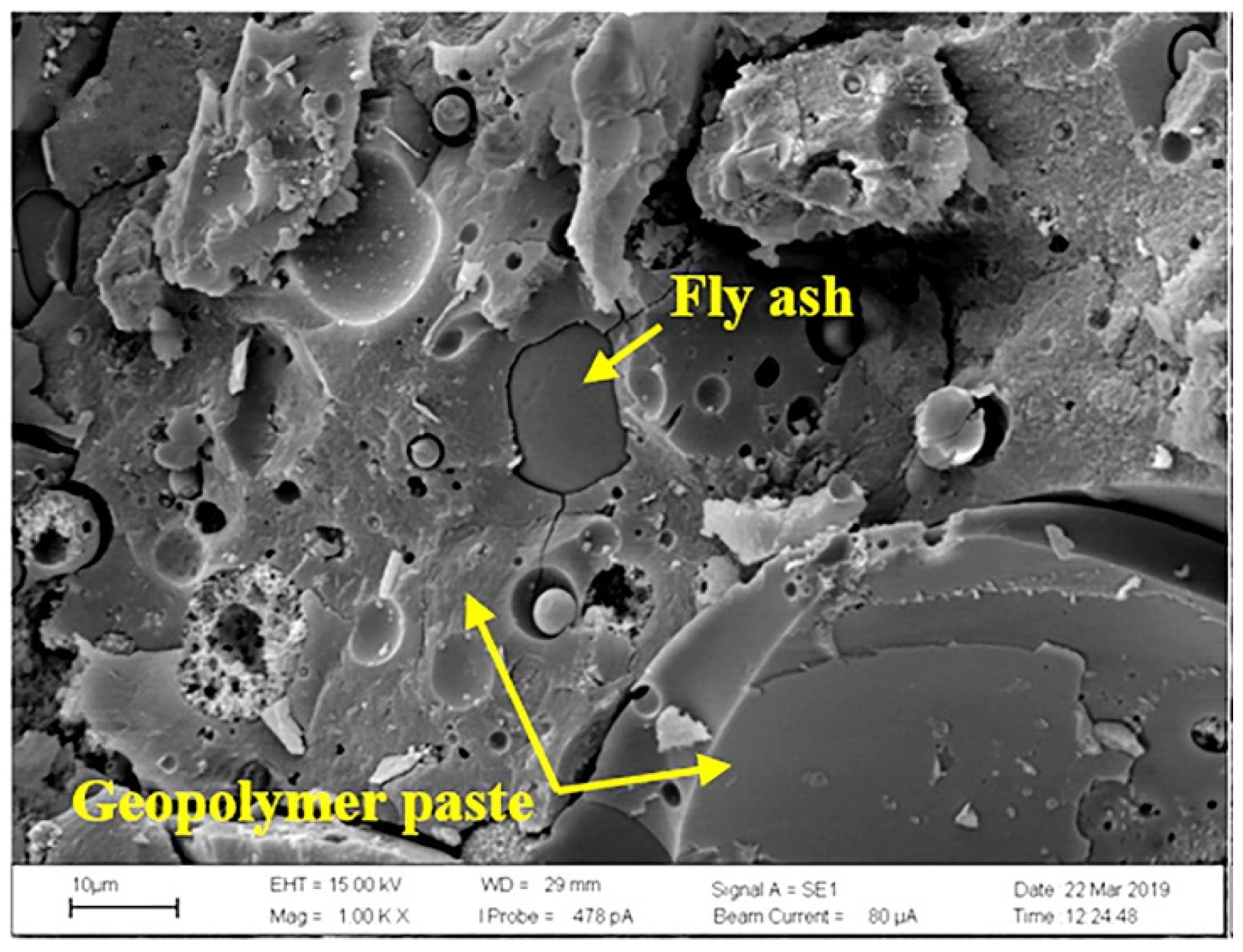
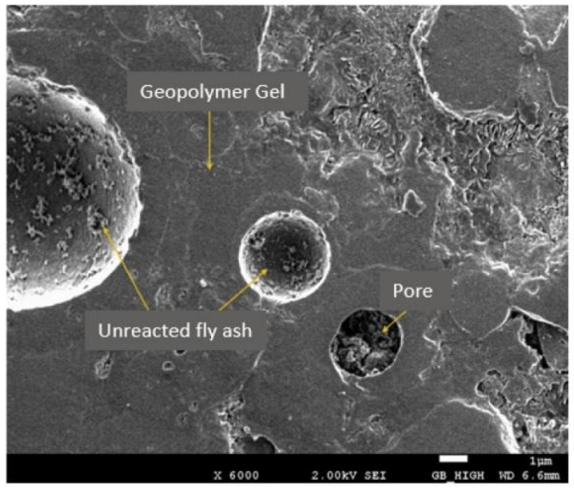
Wongsa et al. [77] analyzed the microstructure and morphology of 100% FA (high calcium) based seven-day geopolymer mortar. Figure 21 shows the SEM micrograph of the fractured specimen surface, with a porosity of around 27.1%, exhibiting a smoother surface validating dense and homogenous geopolymerization matrix with notifiable unreacted FA particles at the fracture surface. The authors outlined the controlled geopolymer mortar as a well-interconnected aluminosilicate network of high calcium fly ash geopolymer composite.

5.2.2. FA-GGBFS-Based Geopolymer Binder

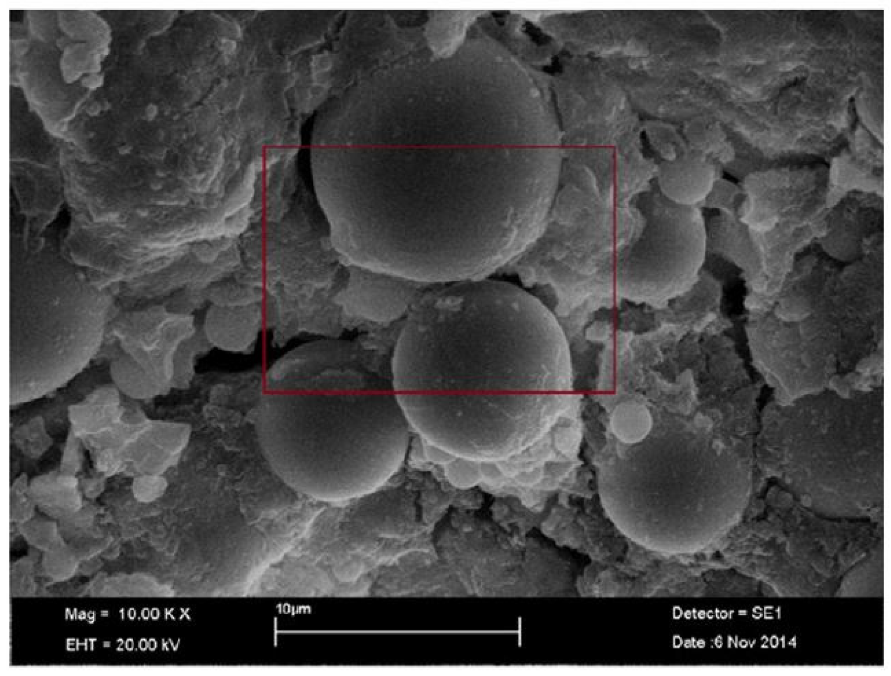
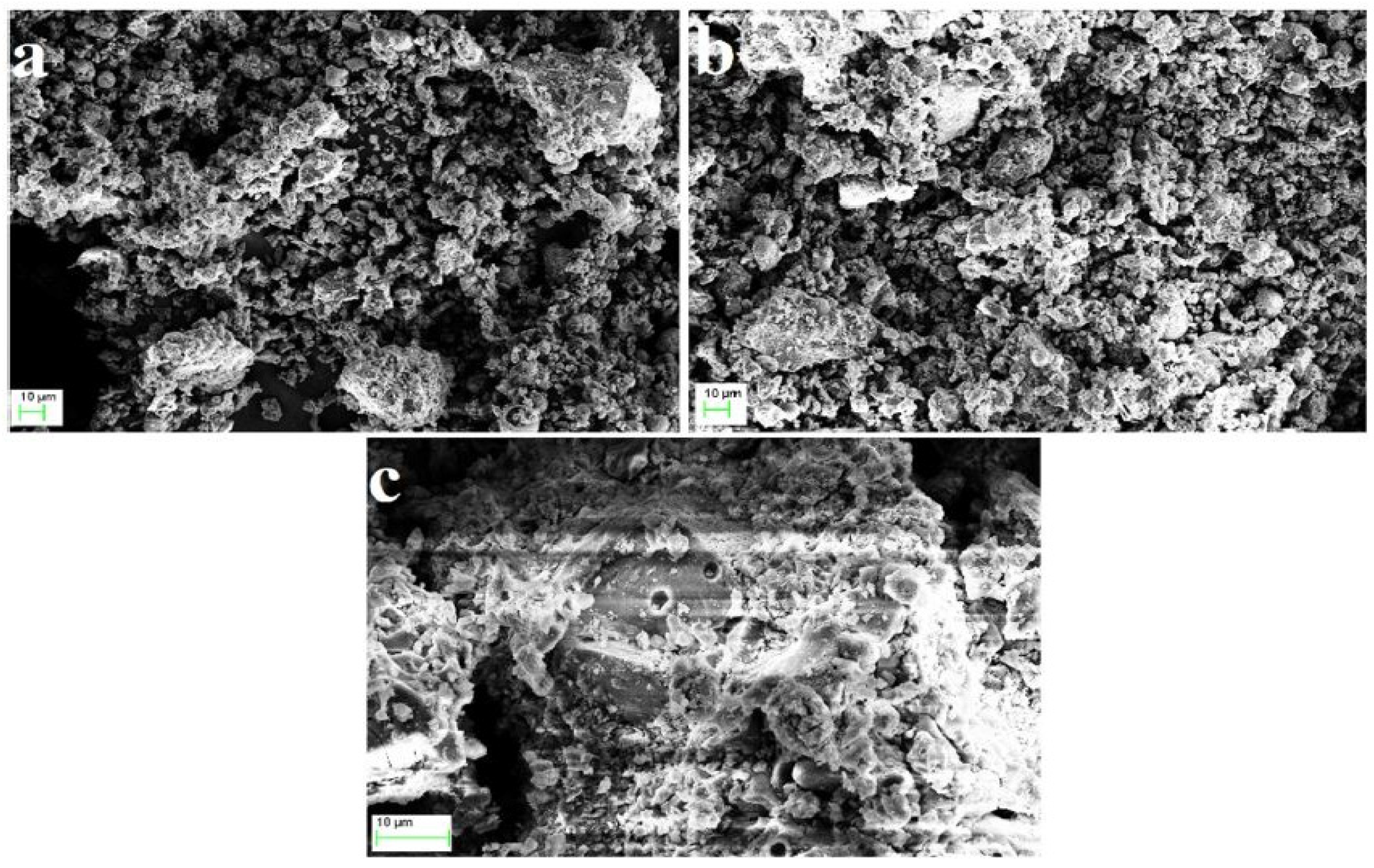
Al-Majidi et al. [125] analyzed the SEM micrographs of the FA-GGBFS mix, cured under ambient conditions for 28 days, to study the microstructural changes in the geopolymer pastes. Figure 22 presents the SEM images of the binder system containing 10% GGBFS subjected to 10,000× magnification. It is reported in the study that the inclusion of GGBFS contributes to the strength enhancement of the geopolymer paste samples. The figure shows that amorphous clusters of GGBFS particles are present together with moderately reacted FA particles inside the geopolymer matrix. In the study, it is emphasized that during geopolymerization, the reactions occur at the external edge of the particles, followed by the subsequent deposition of the reaction products, rather than complete dissolution. The micrograph demonstrates this behavior, which has also been confirmed by Izquierdo et al. [126]. In addition, as GGBFS is a source of high calcium, this leads to the significant formation of C-A-S-H gel in the matrix [127], which enabled the development of a denser microstructure compared to binders made out of FA only. Hence, consequent improvements in the compressive strength were identified with the inclusion of GGBFS into the geopolymer binder system.
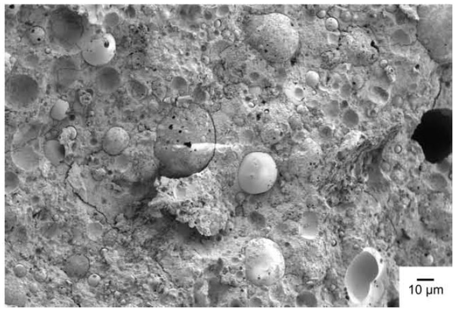
In a study by Panda et al. [128], the authors evaluated the possibility of using FA and GGBFS to prepare geopolymer mortars for the additive manufacturing of the structural elements. They mixed 28.85% FA with 1.68% GGBFS and 3.36% silica fume (by wt.), and the resultant geopolymer mortar mix was subjected to 3D printing methods. The SEM micrographs of the printed geopolymer sample are presented in Figure 23. From the figure, it is evident that the incorporation of GGBFS has aided the formation of sufficient geopolymer gels, eventually producing a hardened and compact microstructure. It is also comprehended from the micrograph that a minor amount of unreacted FA particles is present inside the matrix. In contrast, most FA particles followed complete dissolution when they came in contact with the alkaline solution. Furthermore, as seen in the figure, the existence of micro-pores within the matrix is the probable cause for the strength reduction of the printed geopolymer samples at later ages.

5.2.3. FA-RM-Based Geopolymer Binder

To study the microstructural changes in the geopolymer matrix composed of RM and FA, Singh et al. [129] analyzed the SEM characteristics of the samples cured under ambient conditions. Figure 24a–c represents the ambient cured samples: (a) GRM30 (with 30% RM), and (b) GRM50 (with 50% RM) under 6 M NaOH, along with (c) GRM30 under 10 M NaOH. It is reported in the study that the compressive strength improved with the addition of RM to the binder system. Figure 24a,b reveals that the geopolymer samples, when activated under 6 M NaOH, exhibited better strength due to significant alkalinity and the improved microstructural packing of RM-FA particles inside the matrix. In the case of 50% RM addition, i.e., GRM50 under 6 M, the amount of unreacted RM particles increased in the matrix, for which the strength enhancement is lower than the sample, containing 30% RM (GRM30). However, when activated under 10 M NaOH, although a compact microstructure is observed, the samples could not reach optimal strength, which might be due to the whitish deposition of excess unreacted alkali leading to less effective geopolymerization, as seen in Figure 24c.
Toniolo et al. [130] investigated the SEM images of the geopolymer binders made with wastes comprising RM and FA, where 30% RM replaced FA (by wt.). The alkaline solution adopted for this study was a mix of Na2SiO3 and NaOH, at a mass ratio of 2.5. The compressive strength of 60 MPa was attained by this mix proportion, which is better than the strength obtained from 10% and 20% RM inclusion. The corresponding SEM micrograph (30% RM–70% FA) is shown in Figure 25. From the figure, it is revealed that the 30% RM-FA-based geopolymer sample has a dense microstructure, which explains its improved strength gain. In addition, the RM particles can agglomerate by themselves, filling the pores/gaps left behind by the FA particles after their dissolution. Therefore, the final microstructure became more compact, enhancing the compressive strength.

5.2.4. IOT-FA-Based Geopolymer Binder

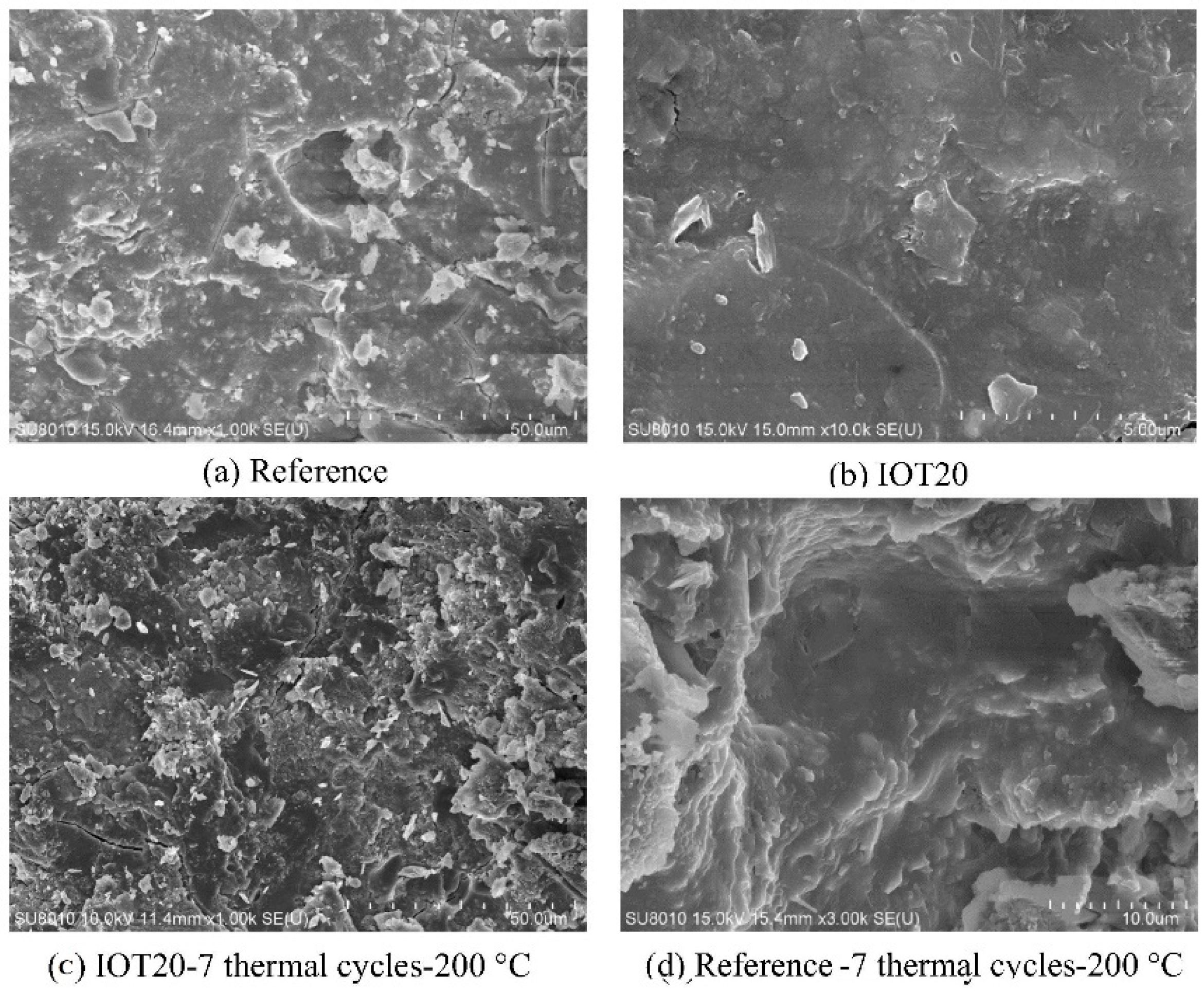
In a study by Duan et al. [99], IOT was blended with FA to prepare geopolymer binders. The mix containing 20% IOT (by wt. of the FA) achieved the maximum compressive strength of 49 MPa and 25 MPa, under standard room temperature and seven thermal cycles (200 °C), respectively. The SEM analysis was conducted to investigate the microstructure of the samples and is shown in Figure 26a–d. From Figure 26a, it is observed that, in the case of the reference sample (containing 0% IOT), micro-cracks in the matrix are formed after 28 days. These micro-cracks are developed due to stress development in the matrix, thereby leading to high porosity and less strength gain. However, from Figure 26b, it is observed that the mix containing 20% IOT carries a denser microstructure in comparison to the reference sample. No pores or micro-cracks are formed, making the microstructure more compact with reduced porosity and, therefore, showed improvement in the compressive strength when cured under standard room temperature. In Figure 26c, following the seven thermal cycles at 200 °C, a very loose structure is observed for the microstructure of the mix containing 20% IOT, with a certain degree of porosity and cracks. However, compared to the mixture containing 0% IOT (Figure 26d), it is found that the microstructure of the 20% IOT sample is denser and offers better thermal resistance in terms of compressive strength. Therefore, it is understood that increasing temperatures increases stress inside the matrix, which ultimately forms pores/cracks, making the microstructure lose. This negatively affects the strength development of the samples. However, the inclusion of 20% IOT into the FA-based geopolymer binder systems is beneficial and effective in case of high temperatures.
In another study by Duan et al. [120], geopolymer binders were prepared using IOT and FA as source materials, where IOT replaced 30% by wt. of FA. The authors investigated the effectiveness of geopolymers for the removal of Cu2+. Two samples were prepared, with and without H2O2 (a foaming agent). After 28 days of curing, the SEM study was conducted to differentiate and identify the microstructures of the resulting geopolymer samples. Figure 27a,b shows the microstructures of reference geopolymer and porous geopolymer (with H2O2), respectively. As seen from the figures, following the geopolymerization, the matrix embodied the aluminosilicate gels. It is observed that the SEM micrograph of the reference geopolymer exhibits a low degree of porosity accompanied by dense microstructure. On the other hand, the porous geopolymer (with H2O2) indicated a high degree of porosity and, consequently, a less dense microstructure.

5.2.5. FA-FCA-Based Geopolymer Binder

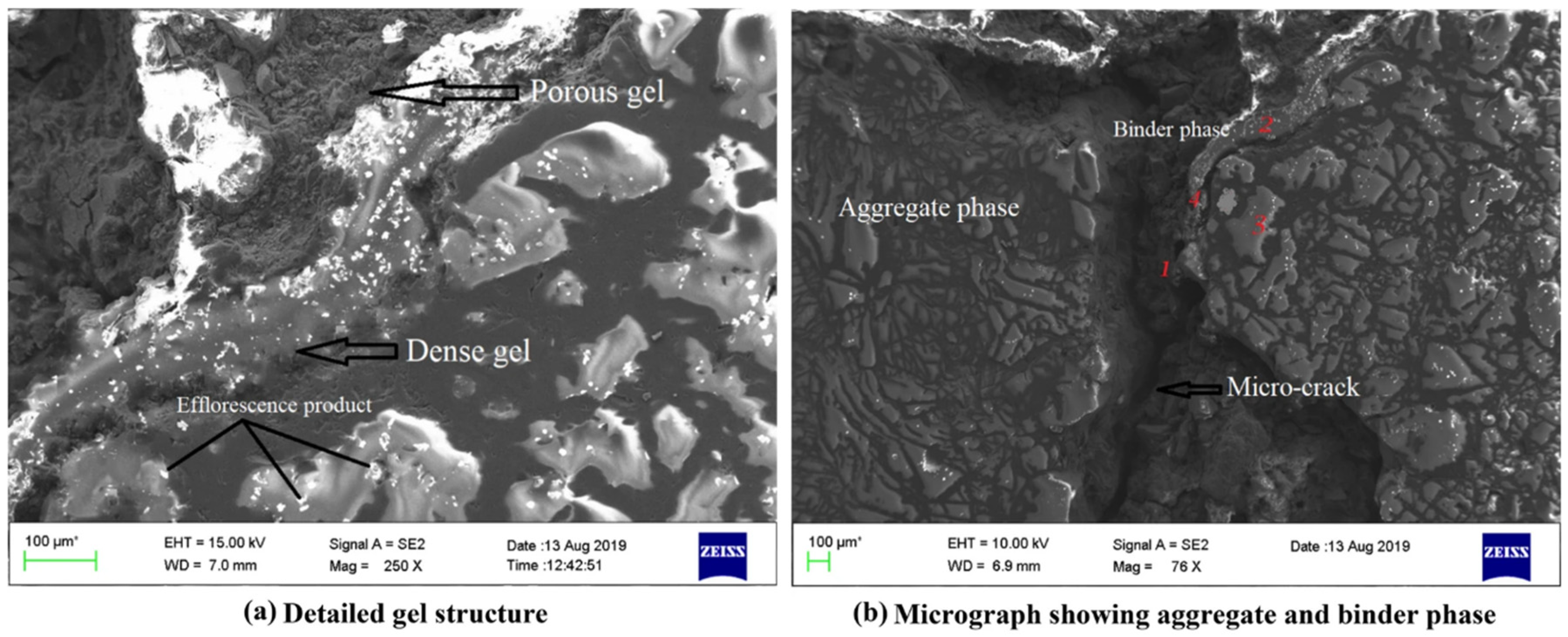
Mishra et al. revealed that the concrete samples made with FCA (60%) and FA (40%) demonstrated a dense heterogeneous geopolymer gel matrix, as shown in Figure 28a [106]. The porous gel phase indicated the partially reacted FCA or FA. In addition, the small dot-spots represent carbonates of Na and Ca, resulting from the reaction of excess unreacted alkalis with atmospheric CO2. Further, from Figure 28b, it is also revealed that between the binder and aggregate phase (ITZ), a large number of microcracks exists; this validates the weak structure of the ITZ.

5.2.6. FA-MK-Based Geopolymer Binder

The microstructure of MK- and FA-based geopolymer was evaluated by Zhang et al. through SEM analysis [108]. Figure 28 shows the development in the microstructure of MK-based geopolymer with 40% FA inclusion from 1, 7 and 28 curing days. Corrosion craters can be seen on the surface of fly ash from the first day of reaction, in Figure 29a, where the aluminosilicate glass in the fly ash particles has receded from the mullite needles that were previously trapped within the fly ash particle. After seven days, as shown in Figure 29b, the glass has further retreated, stipulating a higher degree of geopolymerization, while the visible pores and reaction products seem more continuous and compact. Finally, in Figure 29c, the 28-day geopolymer gel had become more compact with reduced pore sizes due to the continued reaction.

5.2.7. FA-SF-Based Geopolymer Binder

SEM analysis of FA-based geopolymers with SF replacement of 0, 2 and 4 wt.% was undertaken by Li et al. to observe the effect of SF on the mechanical strength of the composite [122]. Figure 30a illustrates the FA control mix geopolymer microstructure, indicating a smooth surface with open pores, cracks and a relatively loose matrix. Introduction of 2 wt.% SF in Figure 30b revealed a denser and homogenous microstructure with a low amount of unreacted fly ash. In contrast, 4 wt.% SF in Figure 30c resulted in broader cracks, a high amount of unreacted fly ash and loose microstructure. The authors concluded that introduction of 2 wt.% SF to be optimum in enhancing the strength of FA-based geopolymer as the compressive strength results supported the microstructural study.

5.3. FTIR

5.3.1. FA-Based Geopolymer Binder

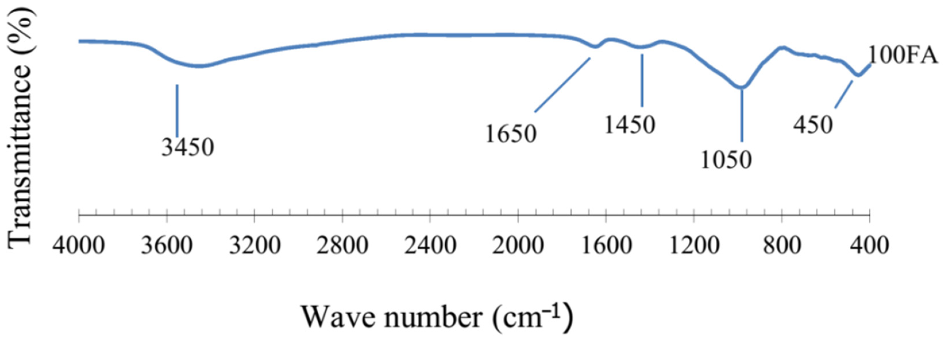
In a study by Tho-In et al. [71], an FTIR investigation of control geopolymer pastes (100% FA), as in Figure 31, was undertaken to comprehend the molecular chemical bonds in a heat-cured geopolymer paste at the age of seven days. The penetrating bands at 3450 cm−1 and 1650 cm−1 pertained to the vibrations of O-H (stretching) and H-O-H (bending) bonds, indicating the presence of absorbed water during geopolymerization. The band at 1450 cm−1 exhibited a stretching vibration of O-C-O in carbonate groups, whereas the bands 450 cm−1 were developed due to the bending and stretching of O-Si-O and Si-O-Si bonds. The band at 1050 cm−1 presented the highest intensity owing to the increased rate of geopolymerization and the asymmetric stretching vibrations of Si-O-X (X = tetrahedral silicon) bonds.
El-Hassan et al. [131] conducted FTIR spectroscopy studies to determine the polymerization degree and reaction products of 100% FA-based geopolymer concrete, cured for 7 and 28 days, under varying temperature conditions (A-Ambient conditions, 30 °C, 60 °C). From Figure 32a, we observe the stretching vibration mode of Si–O–X (X = Si or Al) on the 820 cm−1. A decreased polymerization degree of silica was identified for the 30 °C cured specimen because of the shift in wavenumber towards a lower wavelength. A band at 1420 cm−1 was spotted for ambient cured samples, indicating the formation of Na2CO3 through the carbonation of unreacted NaOH. The bands from 1600–3600 cm−1 were linked to –OH bending and H–O–H stretching vibrations and were similar for all the geopolymer mixes. The presence of water and the occurrence of geopolymer reactions in the concrete specimens can be authenticated through these bands. Growth in H–O–H stretching vibrations at the 3500 cm−1 bands were spotted in Figure 32b, in contrast with Figure 32a, validating that extended curing could assist in the growth of geopolymerization reactions and yield more polymerization products.
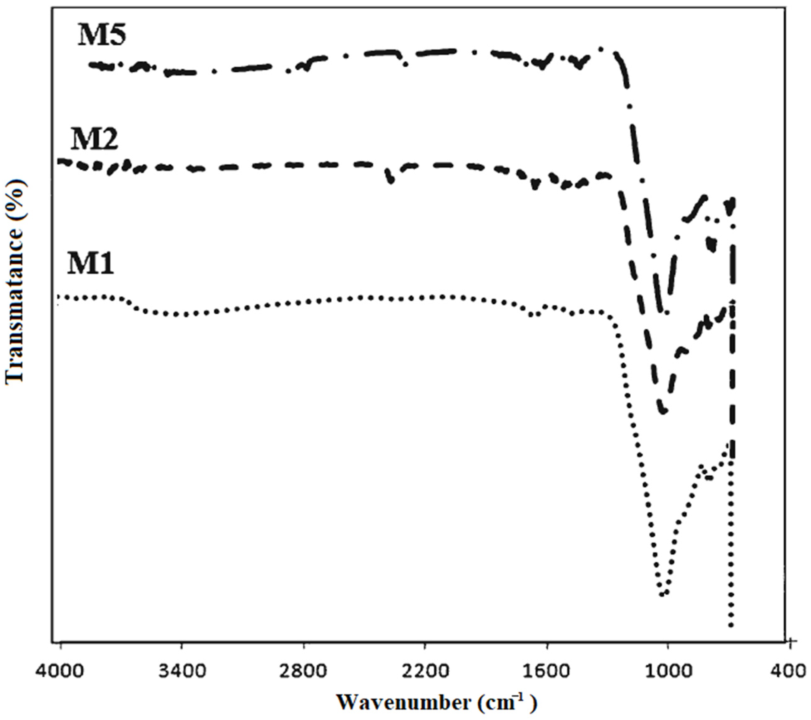
Morsy et al. [132] analyzed the reaction of utilizing different sodium silicate/sodium hydroxide-10 M (S/N) ratios (M1-0.5, M2-1.0, M5-2.5) on the microstructure of 100% FA geopolymer mortar. Figure 33 depicts a broad constituent around 1004 cm−1 because of the Si–O–Si and Al–O–Si asymmetric stretching vibration, and the graph became sharper while moving towards lower bands (995, 979 and 975 cm−1) when the S/N ratio rises from 0.5 to 2.5. The bands between 995 cm−1 and 790 cm−1 were allocated towards Al–OH and Al–O, respectively. The primary transmittance bands for the mortars lie between 900–1300 cm−1 as M2 obtains the maximum compressive strength. This could be attributed to the combined effect of the increased curing temperature, S/N ratio (1.0) and Si/Al ratio resulting in an extensively accelerated geopolymerization process.

5.3.2. FA-GGBFS-Based Geopolymer Binder

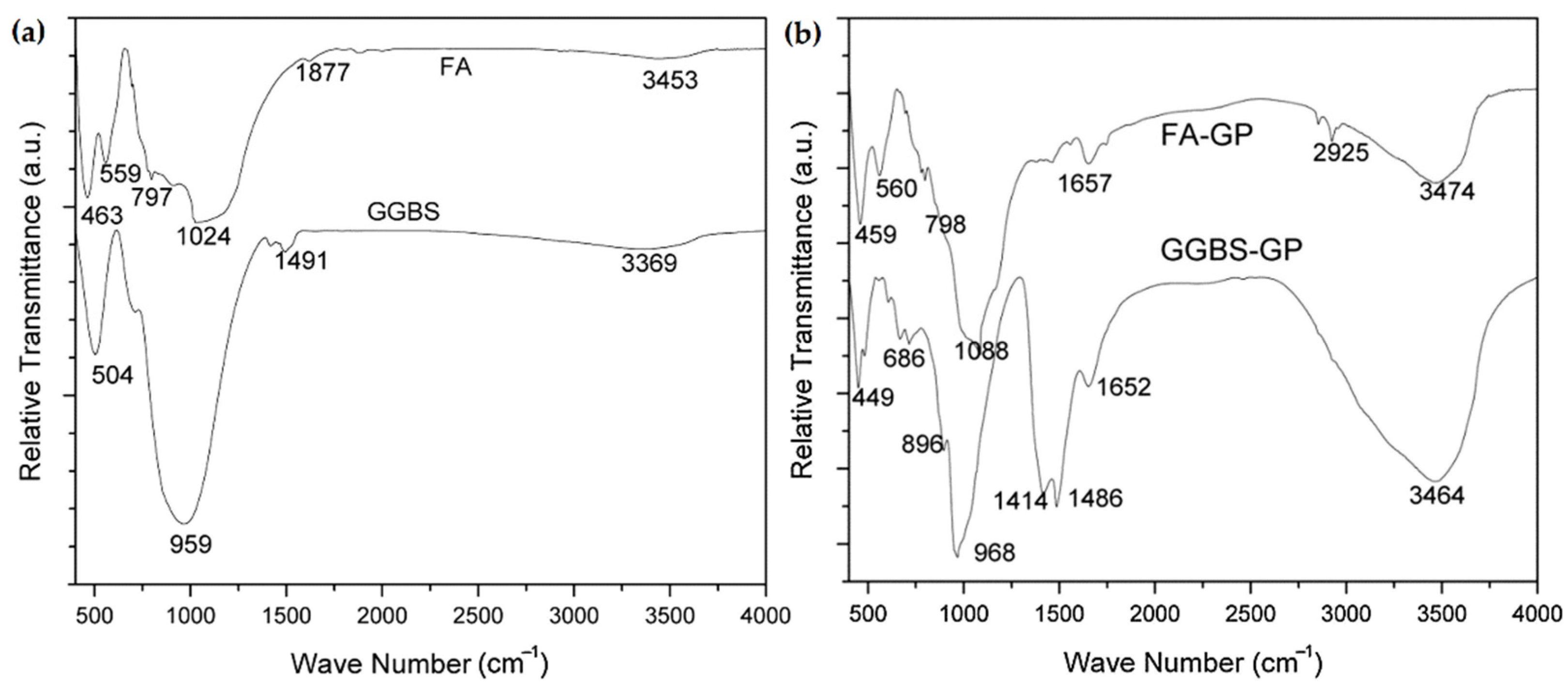
Samantasinghar and Singh [133] examined the FTIR bands of geopolymer binders composed of FA and GGBFS, 0–100% at intervals of 20%, including 100% FA and 100% GGBFS mixes, cured under ambient conditions. For comparison, the FTIR spectra of individual source materials (FA and GGBFS), and the resulting FA-GGBFS geopolymers are shown in Figure 34a,b, respectively. In Figure 34, FA-GP and GGBS-GP represent the mixes containing a minimum of 50% of either FA or GGBFS, respectively. It is observed from the figures that, due to the occurrence of some new peaks and the difference in peak locations, the FTIR spectra of geopolymers made up of FA and GGBFS differ from the individual source materials. In Figure 34b, the peaks at low frequencies (449–560 cm−1) indicate the presence of silicates. The symmetric stretching vibration of the Si-O-Al bond is designated by the peaks in the range of 686–896 cm−1, while the peaks identify the asymmetric stretching vibration of the Si-O-Al bond at 968 and 1088 cm−1. Compared with the FTIR spectra of source materials, the shifting of the peaks in the case of geopolymers reveals the formation of aluminosilicate gels occurs because of the presence of silicon and aluminium in the source materials. This shifting of the peaks influences the strength development in the resulting geopolymer samples. In Figure 34b, in the case of GGBFS-based geopolymers, the bands formed at 1414 and 1486 cm−1 result from O-C-O bond stretching, which signifies that the GGBFS absorbed the CO2 during geopolymerization. Some minor peaks, at 1652, 1657 and 2925 cm−1, reveal the existence of bound water, generated due to H-O-H bond bending. The broad bands observed at 3464 and 3474 cm−1 are because of the stretching of O-H bond units. These O-H bond units are also witnessed in the FTIR spectra of source materials; however, the peaks are not sharp in source materials. The observations carried out in this study are also confirmed in past studies [134,135].
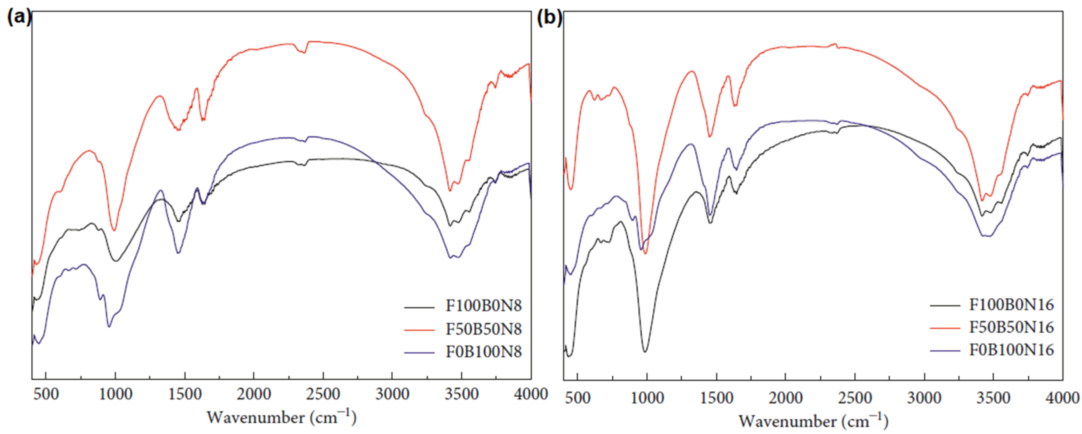
In an effort to understand the bond characteristics, Qiu et al. [123] examined the FTIR spectra of the geopolymer pastes made up of FA and GGBFS, after eight days of curing under room temperature conditions. Figure 35a,b exhibits the FTIR spectra of FA-GGBFS samples activated with 8 M NaOH and 16 M NaOH solutions, respectively. In the figures, FxByNz denotes Fx-FA%, By-GGBFS%, and Nz-molarity of NaOH. Following the activation by 8 M and 16 M NaOH, the FTIR spectra exhibit the shifting of Si-O-Al bonds to a low-frequency region (997 cm−1); this indicates the pattern of new aluminosilicate compounds such as N-A-S-H gels [136]. Simultaneously, the formation of N-A-S-H gels is also revealed by bands at 780 and 580 cm−1 due to symmetric stretching vibrations of Al/Si-O-Si bonds [137]. These modifications are similar in the case of samples activated by 8 M and 16 M NaOH. However, in the case of the FTIR spectra of 16 M NaOH, the peaks are sharper, suggesting the formation of more N-A-S-H gels in the matrix; this observation is in line with [138,139]. In addition, the increase in the intensity of the O-H bands at 1650 and 3420 cm−1 is supported by the inclusion of OH from NaOH solution in both the samples (8 M NaOH and 16 M NaOH).

5.3.3. FA-RM-Based Geopolymer Binder

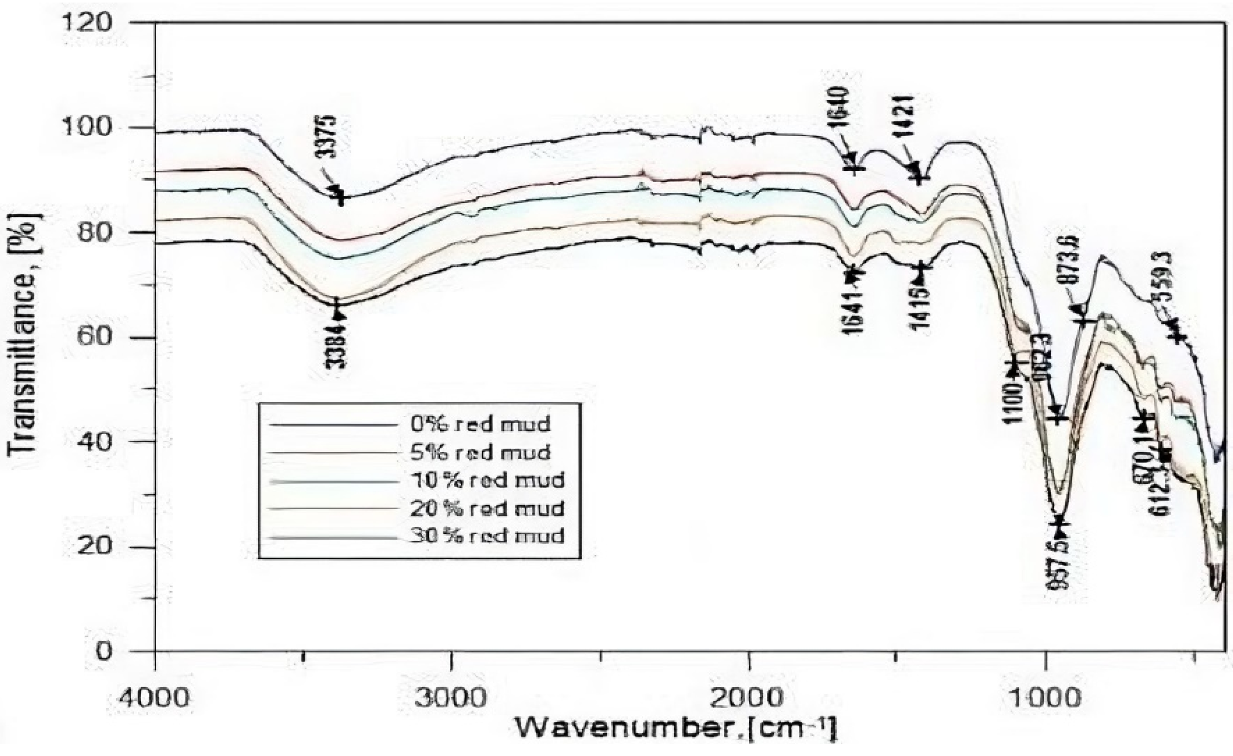
Mucsi et al. [140] investigated the inclusion of RM (0–30% by wt.) into the FA-based geopolymer binder system to enhance the compressive strength of the samples. The compressive strength test results demonstrated that up to 15% RM addition, there is an improvement in the strength of the samples. The FTIR spectra of the RM-FA-based geopolymer samples are displayed in Figure 36. From the figure, it is observed that the peaks which appear in the bands 3390–3370 cm−1 are identified with -OH groups, while the peaks at 1640 cm−1 are associated with H-O-H bending vibrations [136]. The asymmetric stretching vibrations due to the existence of Al/Si-O-Si bonds are exhibited by the peaks at 1100–445 cm−1. After adding RM (5%, 10%, 20%, 30%), the newly developed mineral bonds are indicated by the peaks at 670 cm−1 and 612 cm−1. The presence of the carbonate group resulting from the interaction of the activator and CO2 is revealed in the matrix from the bands at 1410–1425 cm−1. In addition, the peak intensity decreased to 1414 from 1421 cm−1 after the addition of RM, which indicates the alteration in the formation of carbonate compounds inside the matrix.
Similarly, in a study by Chandra et al. [141], FTIR analysis was conducted for the geopolymer binder consisting of 80% RM and 20% FA by wt., which was activated by an alkaline solution composed of 90% 8 M NaOH and 10% Na2SiO3 solution. Figure 37 displays the FTIR spectra after 28 days of curing. From the figure, the appearance of the new bands is confirmed by the peaks at 1643 and 3438.33 cm−1. It is noticed that, due to the presence of symmetric and asymmetric stretching of Si-O and Al-O bonds in the matrix, there happens to be a shift of the peaks to lower frequency regions (991.03 cm−1). Hence, chemical modifications of the matrix and the formation of Si-O and Al-O bonds resulted in effective geopolymerization of the binder samples.

5.3.4. FA-IOT-Based Geopolymer Binder

To date, no Study has been conducted to investigate the bond characteristics of an IOT-based geopolymer binder system prepared with FA.

5.3.5. FA-FCABased Geopolymer Binder

Mishra et al. found that the FTIR spectra of the specimen mix involving FCA (60%) and FA (40%) indicated the presence of asymmetric stretching of –Si–O–T (T = Si or A) band at 1007 cm−1, as shown in Figure 38 [24,48,106]. The figure shows that the free and bound water molecules corresponding to the-OH groups are detected at 3440 cm−1 and 1650 cm−1. The bands at 600 cm−1 correspond to the stretching vibration of –Mg–O–Mg-O– and signify the presence of N-M-A-S-H or M-A-S-H type (Mg bearing) gel phases. Similarly, the bands at 1430–1450 cm−1 indicate the presence of C-O bonds due to efflorescence. As the source material mix containing FCA and FA have high iron content, the bands at 458 cm−1 and 484 cm−1 indicate the presence of a Fe-O bond that can be linked to the chain of Fe-O-Si-O-Al-O-.

5.3.6. FA-MK-Based Geopolymer Binder

No FTIR study has been reported to date regarding the combination of MK-FA-based geopolymer specimens

5.3.7. FA-SF-Based Geopolymer Binder

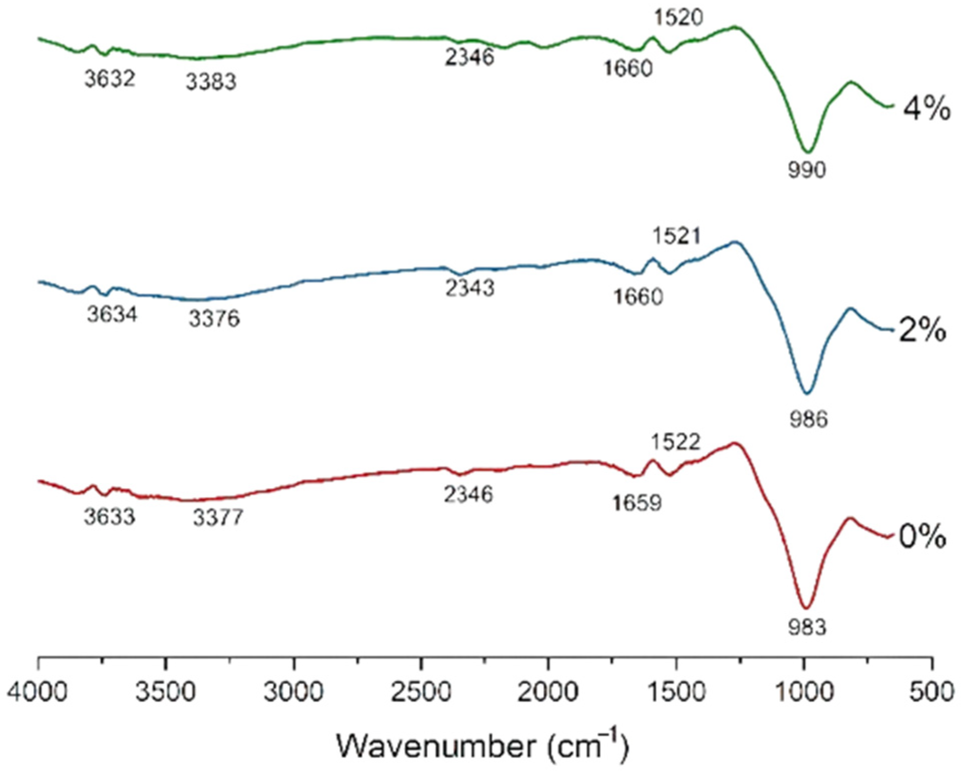
In a study by Li et al., ambient cured geopolymers, with different doses of SF (0, 2, 4 wt.%), were characterized by FTIR analysis to examine the functional groups and bond vibration frequencies in the composite [122]. Absorption bands in Figure 39 were found to be in close resemblance to the control specimen with O-H stretching vibrations corresponding to 3300 cm−1. The band at 983 cm−1 was supported by the development of an amorphous Al-Si gel phase through the alkali activation of amorphous fly ash. The introduction of SF increased the wavenumber from 983 cm−1 to 990 cm−1 without generating any additional bands associated with the generation of the Si bond-rich geopolymer network. Table 6 demonstrates the FTIR spectra of geopolymers with different binder compositions.
Many techniques have been used by researchers worldwide to analyze the microstructure properties of geopolymer samples (paste, mortar, concrete). The tests are conducted with the help of instruments that have a respective degree of precision, influencing the results and our understanding. The types and specifications of the instruments used in the microstructure characterization of FA-based geopolymer binders are presented in Table 7 below:

6. Discussion

This study discussed the effect of chemical compositions of the source materials, especially the role of SiO2, Al2O3, CaO, Fe2O3, and MgO, in the formation of a geopolymer binder structure. Table 1 highlights the chemical compositions (SiO2, Al2O3, CaO, Fe2O3, MgO) of the source materials considered for the study: FA, GGBFS, RM, IOT, FCA, MK, and SF. It is found that the chemical compositions of every source material vary under the influence of the method of their generation. Therefore, it is critical to study each source material combination before reaching any solid base of knowledge regarding the end properties of the geopolymer binders. The significance of chemical oxides, namely SiO2, Al2O3, CaO, Fe2O3, and MgO, has been described in the formation of a geopolymer binder structure. With the exception of SiO2 and Al2O3, the geopolymerization also depends on the presence of CaO, Fe2O3, and MgO in the source materials. These industrial wastes may therefore serve as a filler or participate in the geopolymer reactions by the formation of alumino-silicate (C-A-S-H/N-A-S-H/M-A-S-H) gels, thus making the geopolymer matrix denser. The geopolymerization highly depends upon the dissolution character of the source materials, which are composed of varying percentages of SiO2, Al2O3, CaO, Fe2O3, and MgO, and it is likely that not every oxide of silicon/aluminium/calcium/iron/magnesium will participate in the reaction process.
Following the role of chemical compositions, in part I, the study reviews the compressive strength properties of 100% FA, along with some blended geopolymer binder systems: FA-GGBFS, RM-FA, IOT-FA, FCA-FA, MK-FA and SF-FA. The compressive strength review demonstrates that there are primary geopolymer gel formations–C-A-S-H/N-A-S-H/C-S-H- that aid in the strength development of the geopolymer products. The RM and IOT contain a high amount of Fe2O3, while FCA and GGBFS are rich in MgO; hence, the role of MgO and Fe2O3 is crucial, and, in turn, influences the strength development of geopolymer products. However, as seen in Table 2, Table 3 and Table 4, the percentage combination of source materials, curing temperature conditions and the molarity of NaOH also significantly impacts the development of strength.
Geopolymerization is a complex phenomenon, and the trend of compressive strength properties is not simple enough to come to any general conclusion. Therefore, part II of the study highlighted the microstructural characteristics (XRD, SEM, FTIR) of the geopolymer binder systems to understand the nature of the internal binder structure. Accordingly, the microstructure studies revealed that each binder composition based on FA provides better density and formation of geopolymer gels that complement the compressive strength properties. Each FA-based binder composition demonstrates the formation of several mineral compounds and associated geopolymer bonds that aid in strength development.

7. Outlook on the Utilization of FA-Based Geopolymer Binders

The easy availability, reliable chemical compositions, and desirable physical properties of FA create the prospects of its utilization in making commercial geopolymer binders. This also means that FA-based geopolymer binders, due to their promising properties, provide the opportunity to minimize the use of cement as a traditional binder material, leading to a low-carbon future. Moreover, the utilization of FA in the preparation of geopolymer binder aids in the conservation of natural resources [146].
Over the last decade, a variety of research has been devoted to improving FA-based geopolymer binders by incorporating other supplementary aluminosilicate wastes. The wastes considered in this review (GGBFS, RM, IOT, FCA, MK, and SF) are recognized to modify the properties of FA-based geopolymer binders. In addition to the use of fibers, nano-materials are observed to improve the mechanical strength and microstructure characteristics [147,148,149,150]. The pore structure of these binders suggests that durability increases in FA-based geopolymer binders as a result of the incorporation of additional wastes in the matrix. Therefore, the implementation of FA-based geopolymer binders becomes a new pathway along with several other industrial wastes, as discussed in this review. Other prospects include emerging applications in geopolymer 3D printing, ceramic coatings, bricks, etc.

8. Conclusions

In this paper, the findings of previous studies regarding the compressive strength and microstructure properties of the FA-based geopolymer binder combinations incorporating GGBFS, RM, IOT, FCA, MK, and SF are studied. Based on the extensive review, the following conclusions are presented:
  • Primarily, the chemical compositions of the FA, esp. SiO2, Al2O3, CaO, Fe2O3, and MgO, play a significant role in the development of geopolymer microstructure.
  • The formation of geopolymer network (Si-O-Al), along with C-A-S-H/N-A-S-H/M-A-S-H/K-A-S-H gels and several other additional/new mineral compounds, significantly influence the compressive strength and microstructure properties of the FA based geopolymer binders.
  • Advanced analyzing techniques, such as XRD and FTIR, are necessary to understand the complex chemical mechanism that facilitates geopolymerization.
  • It could be stated that owing to the excellent geopolymerization behavior, the RM, GGBFS, IOT, FCA, MK, and SF combined with FA could be used as an alternative binder to conventional cement-based binders.
  • As geopolymer binders involve different chemistry, compared to cement-water interaction, analyzing microstructure analysis and compressive strength properties provides us with a complete understanding to further address the research gaps and, thereby, improve the already developed FA-based geopolymer binders.

Author Contributions

Conceptualization: J.M.; Writing-original draft preparation: J.M. and R.S.K.; Writing-review and editing: B.N.; Supervision: B.N. and S.K.P. All authors have read and agreed to the published version of the manuscript.

Funding

This research received no external funding.

Institutional Review Board Statement

Not applicable.

Informed Consent Statement

Not applicable.

Data Availability Statement

Not applicable.

Acknowledgments

This review study is part of a PhD project conducted with the collaboration of the Veer Surendra Sai University of Technology, Burla, India and CSIR-Institute of Minerals and Materials Technology, Bhubaneswar, India. The needful motivation from Shaswat Ku. Das and Syed M. Mustakim (CSIR-IMMT), during this study, are highly acknowledged.

Conflicts of Interest

All authors certify that they did not receive support from any organization for the submitted work and have no relevant financial or non-financial interests to disclose.

Abbreviations

FAFly Ash
GGBFSGround Granulated Blast Furnace Slag
RMRed Mud
IOTIron Ore Tailings
FCAFerrochrome Ash
MKMetakaolin
SFSilica Fume
XRDX-ray Diffraction
SEMScanning electron Microscope
FTIRFourier-Transform Infrared Spectroscopy
RCARecycled Coarse Aggregates
MMullite
QQuartz
KKaolinite
NaNacrite
HeHematite
CaCalcite
ITZInterfacial Transition Zone
FFAClass F Fly Ash

References

  1. Akbar, A.; Farooq, F.; Shafique, M.; Aslam, F.; Alyousef, R.; Alabduljabbar, H. Sugarcane Bagasse Ash-Based Engineered Geopolymer Mortar Incorporating Propylene Fibers. J. Build. Eng. 2021, 33, 101492. [Google Scholar] [CrossRef]
  2. Kumar, M.; Kumar, A. Geopolymer Cement: An Initiative towards the Replacement of Grey Cement by Green Cement in Future. J. Build. Mater. Struct. 2021, 8, 1–8. [Google Scholar] [CrossRef]
  3. Zhang, Z.; Yu, H.; Xu, M.; Cui, X. Preparation, Characterization and Application of Geopolymer-Based Tubular Inorganic Membrane. Appl. Clay Sci. 2021, 203, 106001. [Google Scholar] [CrossRef]
  4. Guo, H.; Yuan, P.; Zhang, B.; Wang, Q.; Deng, L.; Liu, D. Realization of High-Percentage Addition of Fly Ash in the Materials for the Preparation of Geopolymer Derived from Acid-Activated Metakaolin. J. Clean. Prod. 2021, 285, 125430. [Google Scholar] [CrossRef]
  5. Saranya, P.; Nagarajan, P.; Shashikala, A.P. Experimental Investigation on Bond Strength Properties of Geopolymer Concrete. In Proceedings of the Lecture Notes in Civil Engineering; Springer: Singapore, 2021; Volume 83, pp. 731–740. [Google Scholar]
  6. Amri, A.; Najib, A.A.; Olivia, M.; Altarawneh, M.; Syam, A.; Rahman, M.M.; Saputro, S.; Wahyuadi, J.; Jiang, Z.T. Physicochemical Properties of Geopolymer Composites with DFT Calculations of In-Situ Reduction of Graphene Oxide. Ceram. Int. 2021, 47, 13440–13445. [Google Scholar] [CrossRef]
  7. Ongpeng, J.M.C.; Guades, E.J.; Promentilla, M.A.B. Cross-Organizational Learning Approach in the Sustainable Use of Fly Ash for Geopolymer in the Philippine Construction Industry. Sustainability 2021, 13, 2454. [Google Scholar] [CrossRef]
  8. Almalkawi, A.T.; Balchandra, A.; Soroushian, P. Potential of Using Industrial Wastes for Production of Geopolymer Binder as Green Construction Materials. Constr. Build. Mater. 2019, 220, 516–524. [Google Scholar] [CrossRef]
  9. Duxson, P.; Fernández-Jiménez, A.; Provis, J.L.; Lukey, G.C.; Palomo, A.; Van Deventer, J.S.J. Geopolymer Technology: The Current State of the Art. J. Mater. Sci. 2007, 42, 2917–2933. [Google Scholar] [CrossRef]
  10. Hardjito, D.; Wallah, S.; Sumajouw, D.M.J.; Rangan, B.V. Brief Review of Development of Geopolymer. In Proceedings of the 8th CANMET/ACI International Conference on Fly Ash, Silica Fume, Slag and Natural Pozzolans in Conerete, Las Vegas, NV, USA, 23–29 May 2004; pp. 1–10. [Google Scholar]
  11. Bernal, S.A.; San Nicolas, R.; Myers, R.J.; Mejía De Gutiérrez, R.; Puertas, F.; Van Deventer, J.S.J.; Provis, J.L. MgO Content of Slag Controls Phase Evolution and Structural Changes Induced by Accelerated Carbonation in Alkali-Activated Binders. Cem. Concr. Res. 2014, 57, 33–43. [Google Scholar] [CrossRef] [Green Version]
  12. Hu, Y.; Liang, S.; Yang, J.; Chen, Y.; Ye, N.; Ke, Y.; Tao, S.; Xiao, K.; Hu, J.; Hou, H.; et al. Role of Fe Species in Geopolymer Synthesized from Alkali-Thermal Pretreated Fe-Rich Bayer Red Mud. Constr. Build. Mater. 2019, 200, 398–407. [Google Scholar] [CrossRef]
  13. Liu, M.; Wu, H.; Yao, P.; Wang, C.; Ma, Z. Microstructure and Macro Properties of Sustainable Alkali-Activated Fly Ash Mortar with Various Construction Waste Fines as Binder Replacement up to 100%. Cem. Concr. Compos. 2022, 134, 104733. [Google Scholar] [CrossRef]
  14. Kumar, A.; Kumar, S. Development of Paving Blocks from Synergistic Use of Red Mud and Fly Ash Using Geopolymerization. Constr. Build. Mater. 2013, 38, 865–871. [Google Scholar] [CrossRef]
  15. Okoye, F.N.; Durgaprasad, J.; Singh, N.B. Effect of Silica Fume on the Mechanical Properties of Fly Ash Based-Geopolymer Concrete. Ceram. Int. 2016, 42, 3000–3006. [Google Scholar] [CrossRef]
  16. Cristelo, N.; Segadães, L.; Coelho, J.; Chaves, B.; Sousa, N.R.; de Lurdes Lopes, M. Recycling Municipal Solid Waste Incineration Slag and Fly Ash as Precursors in Low-Range Alkaline Cements. Waste Manag. 2020, 104, 60–73. [Google Scholar] [CrossRef]
  17. Cristelo, N.; Coelho, J.; Miranda, T.; Palomo, Á.; Fernández-Jiménez, A. Alkali Activated Composites–An Innovative Concept Using Iron and Steel Slag as Both Precursor and Aggregate. Cem. Concr. Compos. 2019, 103, 11–21. [Google Scholar] [CrossRef]
  18. Walkley, B.; San Nicolas, R.; Sani, M.-A.; Rees, G.J.; Hanna, J.V.; Van Deventer, J.S.J.; Provis, J.L. Phase Evolution of C-(A)-S-H/N-A-S-H Gel Blends Investigated via Alkali-Activation of Synthetic Calcium Aluminosilicate Precursors. Elsevier 2016, 89, 120–135. [Google Scholar] [CrossRef] [Green Version]
  19. Davidovits, J. Geopolymers-Inorganic Polymeric New Materials. J. Therm. Anal. 1991, 37, 1633–1656. [Google Scholar] [CrossRef]
  20. Wang, Y.; Liu, X.; Zhang, W.; Li, Z.; Zhang, Y.; Li, Y.; Ren, Y. Effects of Si/Al Ratio on the Efflorescence and Properties of Fly Ash Based Geopolymer. J. Clean. Prod. 2020, 244, 118852. [Google Scholar] [CrossRef]
  21. Bellum, R.R.; Muniraj, K.; Indukuri, C.S.R.; Madduru, S.R.C. Investigation on Performance Enhancement of Fly Ash-GGBFS Based Graphene Geopolymer Concrete. J. Build. Eng. 2020, 32, 101659. [Google Scholar] [CrossRef]
  22. Kuranchie, F.A.; Shukla, S.K.; Habibi, D. Utilisation of Iron Ore Mine Tailings for the Production of Geopolymer Bricks. Int. J. Min. Reclam. Environ. 2016, 30, 92–114. [Google Scholar] [CrossRef]
  23. Zhou, W.; Shi, X.; Lu, X.; Qi, C.; Luan, B.; Liu, F. The Mechanical and Microstructural Properties of Refuse Mudstone-GGBS-Red Mud Based Geopolymer Composites Made with Sand. Constr. Build. Mater. 2020, 253, 119193. [Google Scholar] [CrossRef]
  24. Mishra, J.; Kumar Das, S.; Krishna, R.S.; Nanda, B.; Kumar Patro, S.; Mohammed Mustakim, S. Synthesis and Characterization of a New Class of Geopolymer Binder Utilizing Ferrochrome Ash (FCA) for Sustainable Industrial Waste Management. Mater. Today Proc. 2020, 33, 5001–5006. [Google Scholar] [CrossRef]
  25. Chen, K.; Wu, D.; Yi, M.; Cai, Q.; Zhang, Z. Mechanical and Durability Properties of Metakaolin Blended with Slag Geopolymer Mortars Used for Pavement Repair. Constr. Build. Mater. 2021, 281, 122566. [Google Scholar] [CrossRef]
  26. Jena, S.; Panigrahi, R.; Sahu, P. Effect of Silica Fume on the Properties of Fly Ash Geopolymer Concrete. In Sustainable Construction and Building Materials. Lecture Notes in Civil Engineering; Springer: Singapore, 2019; pp. 145–153. [Google Scholar]
  27. Mallikarjuna Rao, G.; Gunneswara Rao, T.D. Final Setting Time and Compressive Strength of Fly Ash and GGBS-Based Geopolymer Paste and Mortar. Arab. J. Sci. Eng. 2015, 40, 3067–3074. [Google Scholar] [CrossRef]
  28. Gunasekara, C.; Law, D.W.; Setunge, S. Long Term Permeation Properties of Different Fly Ash Geopolymer Concretes. Constr. Build. Mater. 2016, 124, 352–362. [Google Scholar] [CrossRef]
  29. Hajimohammadi, A.; van Deventer, J.S.J. Characterisation of One-Part Geopolymer Binders Made from Fly Ash. Waste Biomass Valorization 2017, 8, 225–233. [Google Scholar] [CrossRef]
  30. Al-mashhadani, M.M.; Canpolat, O.; Aygörmez, Y.; Uysal, M.; Erdem, S. Mechanical and Microstructural Characterization of Fiber Reinforced Fly Ash Based Geopolymer Composites. Constr. Build. Mater. 2018, 167, 505–513. [Google Scholar] [CrossRef]
  31. Naghizadeh, A.; Ekolu, S.O. Method for Comprehensive Mix Design of Fly Ash Geopolymer Mortars. Constr. Build. Mater. 2019, 202, 704–717. [Google Scholar] [CrossRef]
  32. Phoo-Ngernkham, T.; Maegawa, A.; Mishima, N.; Hatanaka, S.; Chindaprasirt, P. Effects of Sodium Hydroxide and Sodium Silicate Solutions on Compressive and Shear Bond Strengths of FA-GBFS Geopolymer. Constr. Build. Mater. 2015, 91, 1–8. [Google Scholar] [CrossRef]
  33. Jawahar, J.G.; Mounika, G. Strength Properties of Fly Ash and GGBS Based Geopolymer Concrete. Asian J. Civ. Eng 2016, 17, 127–135. [Google Scholar]
  34. Palankar, N.; Ravi Shankar, A.U.; Mithun, B.M. Investigations on Alkali-Activated Slag/Fly Ash Concrete with Steel Slag Coarse Aggregate for Pavement Structures. Int. J. Pavement Eng. 2017, 18, 500–512. [Google Scholar] [CrossRef]
  35. Samantasinghar, S.; Singh, S.P. Synthesis of Fly Ash-GGBS-Blended Geopolymer Composits; Springer: Singapore, 2019; Volume 16, ISBN 9789811308994. [Google Scholar]
  36. Shahmansouri, A.A.; Akbarzadeh Bengar, H.; Ghanbari, S. Compressive Strength Prediction of Eco-Efficient GGBS-Based Geopolymer Concrete Using GEP Method. J. Build. Eng. 2020, 31, 101326. [Google Scholar] [CrossRef]
  37. McDonald, J.E.D.; Roache, S.C.; Kawatra, S.K. Repurposing Mine Tailings: Cold Bonding of Siliceous Iron Ore Tailings. Miner. Metall. Process. 2016, 33, 47–52. [Google Scholar] [CrossRef]
  38. Tian, Z.X.; Zhao, Z.H.; Dai, C.Q.; Liu, S.J. Experimental Study on the Properties of Concrete Mixed with Iron Ore Tailings. Adv. Mater. Sci. Eng. 2016, 2016, 8606505. [Google Scholar] [CrossRef] [Green Version]
  39. Galvão, J.L.B.; Andrade, H.D.; Brigolini, G.J.; Peixoto, R.A.F.; Mendes, J.C. Reuse of Iron Ore Tailings from Tailings Dams as Pigment for Sustainable Paints. J. Clean. Prod. 2018, 200, 412–422. [Google Scholar] [CrossRef]
  40. Zhang, C.; Li, S. Utilization of Iron Ore Tailing for the Synthesis of Zeolite A by Hydrothermal Method. J. Mater. Cycles Waste Manag. 2018, 20, 1605–1614. [Google Scholar] [CrossRef]
  41. do Carmo e Silva Defáveri, K.; dos Santos, L.F.; Franco de Carvalho, J.M.; Peixoto, R.A.F.; Brigolini, G.J. Iron Ore Tailing-Based Geopolymer Containing Glass Wool Residue: A Study of Mechanical and Microstructural Properties. Constr. Build. Mater. 2019, 220, 375–385. [Google Scholar] [CrossRef]
  42. Hairi, S.N.M.; Jameson, G.N.L.; Rogers, J.J.; MacKenzie, K.J.D. Synthesis and Properties of Inorganic Polymers (Geopolymers) Derived from Bayer Process Residue (Red Mud) and Bauxite. J. Mater. Sci. 2015, 50, 7713–7724. [Google Scholar] [CrossRef]
  43. Singh, S.; Aswath, M.U.; Ranganath, R.V. Durability of Red Mud Based Geopolymer Paste in Acid Solutions. Mater. Sci. Forum 2016, 866, 99–105. [Google Scholar] [CrossRef]
  44. Hoc Thang, N.; Kien, P.T.; Abdullah, M.M.A.B. Lightweight Heat Resistant Geopolymer-Based Materials Synthesized from Red Mud and Rice Husk Ash Using Sodium Silicate Solution as Alkaline Activator. MATEC Web Conf. 2017, 97, 01119. [Google Scholar] [CrossRef] [Green Version]
  45. Novais, R.M.; Carvalheiras, J.; Seabra, M.P.; Pullar, R.C.; Labrincha, J.A. Innovative Application for Bauxite Residue: Red Mud-Based Inorganic Polymer Spheres as PH Regulators. J. Hazard. Mater. 2018, 358, 69–81. [Google Scholar] [CrossRef] [PubMed]
  46. Chen, X.; Guo, Y.; Ding, S.; Zhang, H.; Xia, F.; Wang, J.; Zhou, M. Utilization of Red Mud in Geopolymer-Based Pervious Concrete with Function of Adsorption of Heavy Metal Ions. J. Clean. Prod. 2019, 207, 789–800. [Google Scholar] [CrossRef]
  47. Chethan, K.B.; Yaragal, S.C.; Das, B.B. Ferrochrome Ash–Its Usage Potential in Alkali Activated Slag Mortars. J. Clean. Prod. 2020, 257, 120577. [Google Scholar] [CrossRef]
  48. Mishra, J.; Das, S.K.; Krishna, R.S.; Nanda, B. Utilization of Ferrochrome Ash as a Source Material for Production of Geopolymer Concrete for a Cleaner Sustainable Environment. Indian Concr. J. 2020, 94, 40–49. [Google Scholar]
  49. Rovnaník, P.; Šafránková, K. Thermal Behaviour of Metakaolin/Fly Ash Geopolymers with Chamotte Aggregate. Materials 2016, 9, 535. [Google Scholar] [CrossRef] [Green Version]
  50. Praveen Kumar, V.V.; Prasad, N.; Dey, S. Influence of Metakaolin on Strength and Durability Characteristics of Ground Granulated Blast Furnace Slag Based Geopolymer Concrete. Struct. Concr. 2020, 21, 1040–1050. [Google Scholar] [CrossRef]
  51. Duan, P.; Yan, C.; Zhou, W. Compressive Strength and Microstructure of Fly Ash Based Geopolymer Blended with Silica Fume under Thermal Cycle. Cem. Concr. Compos. 2017, 78, 108–119. [Google Scholar] [CrossRef]
  52. Nath, S.K.; Kumar, S. Role of Particle Fineness on Engineering Properties and Microstructure of Fly Ash Derived Geopolymer. Constr. Build. Mater. 2020, 233, 117294. [Google Scholar] [CrossRef]
  53. Zuhua, Z.; Xiao, Y.; Huajun, Z.; Yue, C. Role of Water in the Synthesis of Calcined Kaolin-Based Geopolymer. Appl. Clay Sci. 2009, 43, 218–223. [Google Scholar] [CrossRef]
  54. Zhang, L.W.; Kai, M.F.; Chen, X.H. Si-Doped Graphene in Geopolymer: Its Interfacial Chemical Bonding, Structure Evolution and Ultrastrong Reinforcing Ability. Cem. Concr. Compos. 2020, 109, 103522. [Google Scholar] [CrossRef]
  55. Walkley, B.; Ke, X.; Hussein, O.H.; Bernal, S.A.; Provis, J.L. Incorporation of Strontium and Calcium in Geopolymer Gels. J. Hazard. Mater. 2020, 382, 121015. [Google Scholar] [CrossRef] [PubMed]
  56. Ye, H.; Huang, L. Degradation Mechanisms of Alkali-Activated Binders in Sulfuric Acid: The Role of Calcium and Aluminum Availability. Constr. Build. Mater. 2020, 246, 118477. [Google Scholar] [CrossRef]
  57. Saini, G.; Vattipalli, U. Assessing Properties of Alkali Activated GGBS Based Self-Compacting Geopolymer Concrete Using Nano-Silica. Case Stud. Constr. Mater. 2020, 12, e00352. [Google Scholar] [CrossRef]
  58. Puligilla, S.; Mondal, P. Role of Slag in Microstructural Development and Hardening of Fly Ash-Slag Geopolymer. Cem. Concr. Res. 2013, 43, 70–80. [Google Scholar] [CrossRef]
  59. Deb, P.S.; Nath, P.; Sarker, P.K. The Effects of Ground Granulated Blast-Furnace Slag Blending with Fly Ash and Activator Content on the Workability and Strength Properties of Geopolymer Concrete Cured at Ambient Temperature. Mater. Des. (1980–2015) 2014, 62, 32–39. [Google Scholar] [CrossRef] [Green Version]
  60. Islam, A.; Alengaram, U.J.; Jumaat, M.Z.; Bashar, I.I. The Development of Compressive Strength of Ground Granulated Blast Furnace Slag-Palm Oil Fuel Ash-Fly Ash Based Geopolymer Mortar. Mater. Des. 2014, 56, 833–841. [Google Scholar] [CrossRef]
  61. Antoni; Wijaya, S.W.; Hardjito, D. Factors Affecting the Setting Time of Fly Ash-Based Geopolymer. Mater. Sci. Forum 2016, 841, 90–97. [Google Scholar] [CrossRef] [Green Version]
  62. Gomes, K.C.; Lima, G.S.T.; Torres, S.M.; De Barros, S.; Vasconcelos, I.F.; Barbosa, N.P. Iron Distribution in Geopolymer with Ferromagnetic Rich Precursor. Mater. Sci. Forum 2010, 643, 131–138. [Google Scholar] [CrossRef]
  63. Davidovits, J.; Davidovits, R. Ferro-Sialate Geopolymers (-Fe-O-Si-O-Al-O-). Tech. Pap. # 27 2020. [Google Scholar] [CrossRef]
  64. Perera, D.S.; Cashion, J.D.; Blackford, M.G.; Zhang, Z.; Vance, E.R. Fe Speciation in Geopolymers with Si/Al Molar Ratio of ∼2. J. Eur. Ceram. Soc. 2007, 27, 2697–2703. [Google Scholar] [CrossRef]
  65. Lemougna, P.N.; MacKenzie, K.J.D.; Jameson, G.N.L.; Rahier, H.; Chinje Melo, U.F. The Role of Iron in the Formation of Inorganic Polymers (Geopolymers) from Volcanic Ash: A 57Fe Mössbauer Spectroscopy Study. J. Mater. Sci. 2013, 48, 5280–5286. [Google Scholar] [CrossRef]
  66. Kaze, C.R.; Djobo, J.N.Y.; Nana, A.; Tchakoute, H.K.; Kamseu, E.; Melo, U.C.; Leonelli, C.; Rahier, H. Effect of Silicate Modulus on the Setting, Mechanical Strength and Microstructure of Iron-Rich Aluminosilicate (Laterite) Based-Geopolymer Cured at Room Temperature. Ceram. Int. 2018, 44, 21442–21450. [Google Scholar] [CrossRef]
  67. Jin, F.; Gu, K.; Al-Tabbaa, A. Strength and Drying Shrinkage of Reactive MgO Modified Alkali-Activated Slag Paste. Constr. Build. Mater. 2014, 51, 395–404. [Google Scholar] [CrossRef]
  68. Jin, F.; Gu, K.; Al-Tabbaa, A. Strength and Hydration Properties of Reactive MgO-Activated Ground Granulated Blastfurnace Slag Paste. Cem. Concr. Compos. 2015, 57, 8–16. [Google Scholar] [CrossRef] [Green Version]
  69. Tennakoon, C.; Nicolas, R.S.; Sanjayan, J.G.; Shayan, A. Thermal Effects of Activators on the Setting Time and Rate of Workability Loss of Geopolymers. Ceram. Int. 2016, 42, 19257–19268. [Google Scholar] [CrossRef]
  70. Huseien, G.F.; Sam, A.R.M.; Alyousef, R. Texture, Morphology and Strength Performance of Self-Compacting Alkali-Activated Concrete: Role of Fly Ash as GBFS Replacement. Constr. Build. Mater. 2021, 270, 121368. [Google Scholar] [CrossRef]
  71. Tho-In, T.; Sata, V.; Boonserm, K.; Chindaprasirt, P. Compressive Strength and Microstructure Analysis of Geopolymer Paste Using Waste Glass Powder and Fly Ash. J. Clean. Prod. 2016, 172, 2892–2898. [Google Scholar] [CrossRef]
  72. Nagajothi, S.; Elavenil, S. Effect of GGBS Addition on Reactivity and Microstructure Properties of Ambient Cured Fly Ash Based Geopolymer Concrete. Silicon 2020, 13, 507–516. [Google Scholar] [CrossRef]
  73. El-Hassan, H.; Ismail, N. Effect of Process Parameters on the Performance of Fly Ash/GGBS Blended Geopolymer Composites. J. Sustain. Cem. Based Mater. 2018, 7, 122–140. [Google Scholar] [CrossRef]
  74. Nuaklong, P.; Sata, V.; Chindaprasirt, P. Properties of Metakaolin-High Calcium Fly Ash Geopolymer Concrete Containing Recycled Aggregate from Crushed Concrete Specimens. Constr. Build. Mater. 2018, 161, 365–373. [Google Scholar] [CrossRef]
  75. Hu, Y.; Tang, Z.; Li, W.; Li, Y.; Tam, V.W.Y. Physical-Mechanical Properties of Fly Ash/GGBFS Geopolymer Composites with Recycled Aggregates. Constr. Build. Mater. 2019, 226, 139–151. [Google Scholar] [CrossRef]
  76. Wongsa, A.; Wongkvanklom, A.; Tanangteerapong, D.; Chindaprasirt, P. Comparative Study of Fire-Resistant Behaviors of High-Calcium Fly Ash Geopolymer Mortar Containing Zeolite and Mullite. J. Sustain. Cement-Based Mater. 2020, 9, 307–321. [Google Scholar] [CrossRef]
  77. Wongsa, A.; Kunthawatwong, R.; Naenudon, S.; Sata, V.; Chindaprasirt, P. Natural Fiber Reinforced High Calcium Fly Ash Geopolymer Mortar. Constr. Build. Mater. 2020, 241, 118143. [Google Scholar] [CrossRef]
  78. Sasui, S.; Kim, G.; Nam, J.; Koyama, T.; Chansomsak, S. Strength and Microstructure of Class-C Fly Ash and GGBS Blend Geopolymer Activated in NaOH & NaOH + Na2SiO3. Materials 2020, 13, 59. [Google Scholar] [CrossRef] [Green Version]
  79. Saha, S.; Rajasekaran, C. Enhancement of the Properties of Fly Ash Based Geopolymer Paste by Incorporating Ground Granulated Blast Furnace Slag. Constr. Build. Mater. 2017, 146, 615–620. [Google Scholar] [CrossRef]
  80. Vishnu, N.; Kolli, R.; Ravella, D.P. Studies on Self-Compacting Geopolymer Concrete Containing Flyash, GGBS, Wollastonite and Graphene Oxide. Mater. Today Proc. 2020, 43, 2422–2427. [Google Scholar] [CrossRef]
  81. Chiranjeevi, K.; Vijayalakshmi, M.M.; Praveenkumar, T.R. Investigation of Fly Ash and Rice Husk Ash-Based Geopolymer Concrete Using Nano Particles. Appl. Nanosci. 2021. [Google Scholar] [CrossRef]
  82. Kumar, B.; Kumar, G.; Rajesh, V. Development of Fly Ash-GGBS Based Self Compacting Geo-Polymer Concrete with and without Steel Fibres. J. Comput. Eng. Phys. Model. 2021, 4, 1–18. [Google Scholar] [CrossRef]
  83. Ramesh, V.; Srikanth, K. Comparison of Mechanical Properties of Flyash-GGBS Based GPC and Flyash-Alccofine Based GPC with Different Concentrations of Alkaline Activators. IOP Conf. Ser. Mater. Sci. Eng. 2021, 1116, 012172. [Google Scholar] [CrossRef]
  84. Poloju, K.K.; Srinivasu, K. Impact of GGBS and Strength Ratio on Mechanical Properties of Geopolymer Concrete under Ambient Curing and Oven Curing. Mater. Today Proc. 2020, 42, 962–968. [Google Scholar] [CrossRef]
  85. Divvala, S.; Rani, M.S. Strength Properties and Durability Studies on Modified Geopolymer Concrete Composites Incorporating GGBS and Metakaolin. Appl. Nanosci. 2021, 1–16. [Google Scholar] [CrossRef]
  86. Goriparthi, M.R.; Gunneswara Rao, T.D. Effect of Fly Ash and GGBS Combination on Mechanical and Durability Properties of GPC. Adv. Concr. Constr. 2017, 5, 313–330. [Google Scholar] [CrossRef]
  87. Rafeet, A.; Vinai, R.; Soutsos, M.; Sha, W. Guidelines for Mix Proportioning of Fly Ash/GGBS Based Alkali Activated Concretes. Constr. Build. Mater. 2017, 147, 130–142. [Google Scholar] [CrossRef] [Green Version]
  88. Prabu, B.; Kumutha, R.; Vijai, K. Effect of Fibers on the Mechanical Properties of Fly Ash and GGBS Based Geopolymer Concrete under Different Curing Conditions. Indian J. Eng. Mater. Sci. 2017, 24, 5–12. [Google Scholar]
  89. Karuppannan, M.S.; Palanisamy, C.; Farook, M.S.M.; Natarajan, M. Study on Fly Ash and GGBS Based Oven Cured Geopolymer Concrete. AIP Conf. Proc. 2020, 2240, 060001. [Google Scholar] [CrossRef]
  90. Ke, X.; Bernal, S.A.; Ye, N.; Provis, J.L.; Yang, J. One-Part Geopolymers Based on Thermally Treated Red Mud/NaOH Blends. J. Am. Ceram. Soc. 2015, 98, 5–11. [Google Scholar] [CrossRef]
  91. Hu, W.; Nie, Q.; Huang, B.; Shu, X.; He, Q. Mechanical and Microstructural Characterization of Geopolymers Derived from Red Mud and Fly Ashes. J. Clean. Prod. 2018, 186, 799–806. [Google Scholar] [CrossRef]
  92. van Deventer, J.S.J.; Provis, J.L.; Duxson, P.; Lukey, G.C. Reaction Mechanisms in the Geopolymeric Conversion of Inorganic Waste to Useful Products. J. Hazard. Mater. 2007, 139, 506–513. [Google Scholar] [CrossRef] [PubMed]
  93. Bellum, R.R.; Venkatesh, C.; Madduru, S.R.C. Influence of Red Mud on Performance Enhancement of Fly Ash-Based Geopolymer Concrete. Innov. Infrastruct. Solut. 2021, 6, 1–9. [Google Scholar] [CrossRef]
  94. Mudgal, M.; Singh, A.; Chouhan, R.K.; Acharya, A.; Srivastava, A.K. Fly Ash Red Mud Geopolymer with Improved Mechanical Strength. Clean. Eng. Technol. 2021, 4, 100215. [Google Scholar] [CrossRef]
  95. Ai, T.; Zhong, D.; Zhang, Y.; Zong, J.; Yan, X.; Niu, Y. The Effect of Red Mud Content on the Compressive Strength of Geopolymers under Different Curing Systems. Buildings 2021, 11, 298. [Google Scholar] [CrossRef]
  96. Bajpai, R.; Shrivastava, A.; Singh, M. Properties of Fly Ash Geopolymer Modified with Red Mud and Silica Fume: A Comparative Study. SN Appl. Sci. 2020, 2, 1846. [Google Scholar] [CrossRef]
  97. Yeddula, B.S.R.; Somasundaram, K. Effect of Red Mud Proportion on the Strength and Microstructure of Ferrosialate Based Geopolymer Mortar. Indian J. Eng. Mater. Sci. 2020, 27, 554–563. [Google Scholar]
  98. Xiaolong, Z.; Shiyu, Z.; Hui, L.; Yingliang, Z. Disposal of Mine Tailings via Geopolymerization. J. Clean. Prod. 2021, 284, 124756. [Google Scholar] [CrossRef]
  99. Duan, P.; Yan, C.; Zhou, W.; Ren, D. Fresh Properties, Compressive Strength and Microstructure of Fly Ash Geopolymer Paste Blended with Iron Ore Tailing under Thermal Cycle. Constr. Build. Mater. 2016, 118, 76–88. [Google Scholar] [CrossRef]
  100. Obenaus-Emler, R.; Falah, M.; Illikainen, M. Assessment of Mine Tailings as Precursors for Alkali-Activated Materials for on-Site Applications. Constr. Build. Mater. 2020, 246, 118470. [Google Scholar] [CrossRef]
  101. Ali, S.U.; Hussin, M.W.; Mirza, J.; Umara Shettima, A.; Hussin, W.; Ahmad, Y. Evaluation of Iron Ore Tailings as Replacement for Fine Aggregate in Concrete. Constr. Build. Mater. 2016, 120, 72–79. [Google Scholar] [CrossRef]
  102. Savraja, H.G.; SUNIL, C.L.; Ramaraju, H.K. Synthesis of Kudremukh Iron Ore Tailing Based Geopolymer Coarse Aggregate Using Fly-Ash as Precursor in the Construction Industry. I-Manag. J. Civ. Eng. 2020, 10, 1–6. [Google Scholar] [CrossRef]
  103. Chinnappa, G.B.; Karra, R.C. Experimental and Statistical Evaluations of Strength Properties of Concrete with Iron Ore Tailings as Fine Aggregate. J. Hazard. Toxic Radioact. Waste 2019, 24, 04019038. [Google Scholar] [CrossRef]
  104. Sharath, B.P.; Shivaprasad, K.N.; Athikkal, M.M.; Das, B.B. Some Studies on Sustainable Utilization of Iron Ore Tailing (IOT) as Fine Aggregates in Fly Ash Based Geopolymer Mortar. IOP Conf. Ser. Mater. Sci. Eng. 2018, 431, 092010. [Google Scholar] [CrossRef]
  105. Saha, S.; Mohanty, T.; Saha, P. Mechanical Properties of Fly Ash and Ferrochrome Ash-Based Geopolymer Concrete Using Recycled Aggregate. In Lecture Notes in Civil Engineering; Springer: Berlin/Heidelberg, Germany, 2021; Volume 75, pp. 417–426. [Google Scholar]
  106. Mishra, J.; Nanda, B.; Patro, S.K.; Das, S.K.; Mustakim, S.M. Influence of Ferrochrome Ash on Mechanical and Microstructure Properties of Ambient Cured Fly Ash-Based Geopolymer Concrete. J. Mater. Cycles Waste Manag. 2022, 24, 1095–1108. [Google Scholar] [CrossRef]
  107. Duan, P.; Yan, C.; Zhou, W. Influence of Partial Replacement of Fly Ash by Metakaolin on Mechanical Properties and Microstructure of Fly Ash Geopolymer Paste Exposed to Sulfate Attack. Ceram. Int. 2016, 42, 3504–3517. [Google Scholar] [CrossRef]
  108. Zhang, Z.; Wang, H.; Zhu, Y.; Reid, A.; Provis, J.L.; Bullen, F. Using Fly Ash to Partially Substitute Metakaolin in Geopolymer Synthesis. Appl. Clay Sci. 2014, 88–89, 194–201. [Google Scholar] [CrossRef]
  109. Memon, F.A.; Nuruddin, M.F.; Shafiq, N. Effect of Silica Fume on the Fresh and Hardened Properties of Fly Ash-Based Self-Compacting Geopolymer Concrete. Int. J. Miner. Metall. Mater. 2013, 20, 205–213. [Google Scholar] [CrossRef]
  110. Sevinç, A.H.; Durgun, M.Y. Properties of High-Calcium Fly Ash-Based Geopolymer Concretes Improved with High-Silica Sources. Constr. Build. Mater. 2020, 261, 120014. [Google Scholar] [CrossRef]
  111. Lv, Q.; Yu, J.; Ji, F.; Gu, L.; Chen, Y.; Shan, X. Mechanical Property and Microstructure of Fly Ash-Based Geopolymer Activated by Sodium Silicate. KSCE J. Civ. Eng. 2021, 25, 1765–1777. [Google Scholar] [CrossRef]
  112. Saludung, A.; Ogawa, Y.; Kawai, K. Microstructure and Mechanical Properties of FA/GGBS-Based Geopolymer. In Proceedings of the MATEC Web of Conferences, Jawa Tengah, Indonesia, 11–12 July 2018; Volume 195. [Google Scholar]
  113. Kamath, M.; Prashant, S.; Kumar, M. Micro-Characterisation of Alkali Activated Paste with Fly Ash-GGBS-Metakaolin Binder System with Ambient Setting Characteristics. Constr. Build. Mater. 2021, 277, 122323. [Google Scholar] [CrossRef]
  114. Zawrah, M.F.; Badr, H.A.; Khattab, R.M. Recycling and Utilization of Some Waste Clays for Production of Sintered Ceramic Bodies. Silicon 2020, 12, 1035–1042. [Google Scholar] [CrossRef]
  115. Navrátilová, E.; Rovnaníková, P. Pozzolanic Properties of Brick Powders and Their Effect on the Properties of Modified Lime Mortars. Constr. Build. Mater. 2016, 120, 530–539. [Google Scholar] [CrossRef]
  116. Yang, Z.; Mocadlo, R.; Zhao, M.; Sisson, R.D.; Tao, M.; Liang, J. Preparation of a Geopolymer from Red Mud Slurry and Class F Fly Ash and Its Behavior at Elevated Temperatures. Constr. Build. Mater. 2019, 221, 308–317. [Google Scholar] [CrossRef]
  117. Temuujin, J.; Minjigmaa, A.; Rickard, W.; Lee, M.; Williams, I.; van Riessen, A. Fly Ash Based Geopolymer Thin Coatings on Metal Substrates and Its Thermal Evaluation. J. Hazard. Mater. 2010, 180, 748–752. [Google Scholar] [CrossRef]
  118. Zhang, M.; Zhao, M.; Zhang, G.; Sietins, J.M.; Granados-Focil, S.; Pepi, M.S.; Xu, Y.; Tao, M. Reaction Kinetics of Red Mud-Fly Ash Based Geopolymers: Effects of Curing Temperature on Chemical Bonding, Porosity, and Mechanical Strength. Cem. Concr. Compos. 2018, 93, 175–185. [Google Scholar] [CrossRef]
  119. Lyu, S.J.; Wang, T.T.; Cheng, T.W.; Ueng, T.H. Main Factors Affecting Mechanical Characteristics of Geopolymer Revealed by Experimental Design and Associated Statistical Analysis. Constr. Build. Mater. 2013, 43, 589–597. [Google Scholar] [CrossRef]
  120. Duan, P.; Yan, C.; Zhou, W.; Ren, D. Development of Fly Ash and Iron Ore Tailing Based Porous Geopolymer for Removal of Cu(II) from Wastewater. Ceram. Int. 2016, 42, 13507–13518. [Google Scholar] [CrossRef]
  121. Yang, T.; Zhu, H.; Zhang, Z. Influence of Fly Ash on the Pore Structure and Shrinkage Characteristics of Metakaolin-Based Geopolymer Pastes and Mortars. Constr. Build. Mater. 2017, 153, 284–293. [Google Scholar] [CrossRef]
  122. Li, O.H.; Yun-Ming, L.; Cheng-Yong, H.; Bayuaji, R.; Abdullah, M.M.A.B.; Loong, F.K.; Jin, T.S.; Teng, N.H.; Nabiałek, M.; Jeż, B.; et al. Evaluation of the Effect of Silica Fume on Amorphous Fly Ash Geopolymers Exposed to Elevated Temperature. Magnetochemistry 2021, 7, 9. [Google Scholar] [CrossRef]
  123. Qiu, J.; Zhao, Y.; Xing, J.; Sun, X. Fly Ash/Blast Furnace Slag-Based Geopolymer as a Potential Binder for Mine Backfilling: Effect of Binder Type and Activator Concentration. Adv. Mater. Sci. Eng. 2019, 2019, 2028109. [Google Scholar] [CrossRef] [Green Version]
  124. Jackson, M.D.; Chae, S.R.; Mulcahy, S.R.; Meral, C.; Taylor, R.; Li, P.; Emwas, A.-H.; Moon, J.; Yoon, S.; Vola, G.; et al. Unlocking the Secrets of Al-Tobermorite in Roman Seawater Concrete. Am. Mineral. 2013, 98, 1669–1687. [Google Scholar] [CrossRef] [Green Version]
  125. Al-Majidi, M.H.; Lampropoulos, A.; Cundy, A.; Meikle, S. Development of Geopolymer Mortar under Ambient Temperature for in Situ Applications. Constr. Build. Mater. 2016, 120, 198–211. [Google Scholar] [CrossRef] [Green Version]
  126. Izquierdo, M.; Querol, X.; Davidovits, J.; Antenucci, D.; Nugteren, H.; Fernández-Pereira, C. Coal Fly Ash-Slag-Based Geopolymers: Microstructure and Metal Leaching. J. Hazard. Mater. 2009, 166, 561–566. [Google Scholar] [CrossRef]
  127. Nath, P.; Sarker, P.K. Effect of GGBFS on Setting, Workability and Early Strength Properties of Fly Ash Geopolymer Concrete Cured in Ambient Condition. Constr. Build. Mater. 2014, 66, 163–171. [Google Scholar] [CrossRef] [Green Version]
  128. Panda, B.; Paul, S.C.; Hui, L.J.; Tay, Y.W.D.; Tan, M.J. Additive Manufacturing of Geopolymer for Sustainable Built Environment. J. Clean. Prod. 2017, 167, 281–288. [Google Scholar] [CrossRef]
  129. Singh, S.; Aswath, M.U.; Ranganath, R.V. Effect of Mechanical Activation of Red Mud on the Strength of Geopolymer Binder. Constr. Build. Mater. 2018, 177, 91–101. [Google Scholar] [CrossRef]
  130. Toniolo, N.; Taveri, G.; Hurle, K.; Roether, J.A.; Ercole, P.; Dlouhý, I.; Boccaccini, A.R. Fly-Ash-Based Geopolymers: How the Addition of Recycled Glass or Red Mud Waste Influences the Structural and Mechanical Properties. J. Ceram. Sci. Technol. 2017, 8, 411–419. [Google Scholar] [CrossRef]
  131. El-Hassan, H.; Ismail, N.; Al Hinaii, S.; Alshehhi, A.; Al Ashkar, N. Effect of GGBS and Curing Temperature on Microstructure Characteristics of Lightweight Geopolymer Concrete. In Proceedings of the MATEC Web of Conferences, Sharjah, United Arab Emirates, 18–20 April 2017; Volume 120, p. 03004. [Google Scholar]
  132. Morsy, M.S.; Alsayed, S.H.; Al-Salloum, Y.; Almusallam, T. Effect of Sodium Silicate to Sodium Hydroxide Ratios on Strength and Microstructure of Fly Ash Geopolymer Binder. Arab. J. Sci. Eng. 2014, 39, 4333–4339. [Google Scholar] [CrossRef]
  133. Samantasinghar, S.; Singh, S.P. Effect of Synthesis Parameters on Compressive Strength of Fly Ash-Slag Blended Geopolymer. Constr. Build. Mater. 2018, 170, 225–234. [Google Scholar] [CrossRef]
  134. Abdel-Gawwad, H.A.; Abo-El-Enein, S.A. A Novel Method to Produce Dry Geopolymer Cement Powder. HBRC J. 2016, 12, 13–24. [Google Scholar] [CrossRef] [Green Version]
  135. Zhang, Z.; Wang, H.; Provis, J.L. Quantitative Study of the Reactivity of Fly Ash in Geopolymerization by Ftir. J. Sustain. Cem. Based Mater. 2012, 1, 154–166. [Google Scholar] [CrossRef] [Green Version]
  136. Panias, D.; Giannopoulou, I.P.; Perraki, T. Effect of Synthesis Parameters on the Mechanical Properties of Fly Ash-Based Geopolymers. Colloids Surf. A Physicochem. Eng. Asp. 2007, 301, 246–254. [Google Scholar] [CrossRef]
  137. Yao, Y.; Sun, H. A Novel Silica Alumina-Based Backfill Material Composed of Coal Refuse and Fly Ash. J. Hazard. Mater. 2012, 213–214, 71–82. [Google Scholar] [CrossRef] [PubMed]
  138. Rattanasak, U.; Chindaprasirt, P. Influence of NaOH Solution on the Synthesis of Fly Ash Geopolymer. Miner. Eng. 2009, 22, 1073–1078. [Google Scholar] [CrossRef]
  139. Ozer, I.; Soyer-Uzun, S. Relations between the Structural Characteristics and Compressive Strength in Metakaolin Based Geopolymers with Different Molar Si/Al Ratios. Ceram. Int. 2015, 41, 10192–10198. [Google Scholar] [CrossRef]
  140. Mucsi, G.; Szabó, R.; Rácz, Á.; Kristály, F.; Kumar, S. Combined Utilization of Red Mud and Mechanically Activated Fly Ash in Geopolymers. Rud. Geol. Naft. Zb. 2019, 34, 27–36. [Google Scholar] [CrossRef] [Green Version]
  141. Chandra, K.S.; Krishnaiah, S.; Reddy, N.G.; Hossiney, N.; Peng, L. Strength Development of Geopolymer Composites Made from Red Mud–Fly Ash as a Subgrade Material in Road Construction. J. Hazard. Toxic. Radioact. Waste 2021, 25, 04020068. [Google Scholar] [CrossRef]
  142. Payakaniti, P.; Chuewangkam, N.; Yensano, R.; Pinitsoontorn, S.; Chindaprasirt, P. Changes in Compressive Strength, Microstructure and Magnetic Properties of a High-Calcium Fly Ash Geopolymer Subjected to High Temperatures. Constr. Build. Mater. 2020, 265, 120650. [Google Scholar] [CrossRef]
  143. Wongkvanklom, A.; Posi, P.; Kampala, A.; Kaewngao, T.; Chindaprasirt, P. Beneficial Utilization of Recycled Asphaltic Concrete Aggregate in High Calcium Fly Ash Geopolymer Concrete. Case Stud. Constr. Mater. 2021, 15, e00615. [Google Scholar] [CrossRef]
  144. Lee, W.H.; Wang, J.H.; Ding, Y.C.; Cheng, T.W. A Study on the Characteristics and Microstructures of GGBS/FA Based Geopolymer Paste and Concrete. Constr. Build. Mater. 2019, 211, 807–813. [Google Scholar] [CrossRef]
  145. Yousefi Oderji, S.; Chen, B.; Ahmad, M.R.; Shah, S.F.A. Fresh and Hardened Properties of One-Part Fly Ash-Based Geopolymer Binders Cured at Room Temperature: Effect of Slag and Alkali Activators. J. Clean. Prod. 2019, 225, 1–10. [Google Scholar] [CrossRef]
  146. Krishna, R.S.; Mishra, J.; Das, S.K.; Nanda, B.; Patro, S.K.; Mustakim, S.M. A Review on Potential of Graphene Reinforced Geopolymer Composites. In Tailored Functional Materials. Springer Proceedings in Materials; Springer: Singapore, 2022; pp. 43–60. [Google Scholar]
  147. Das, S.K.; Krishna, R.S.; Mishra, S.; Mustakim, S.M.; Jena, M.K.; Tripathy, A.K.; Sahu, T. Future Trends Nanomaterials in Alkali-Activated Composites. In Handbook of Sustainable Concrete and Industrial Waste Management; Colangelo, F., Cioffi, R., Farina, I., Eds.; Woodhead Publishing: Sawston, UK, 2021. [Google Scholar]
  148. Krishna, R.S.; Mishra, J.; Meher, S.; Das, S.K.; Mustakim, S.M.; Singh, S.K. Industrial Solid Waste Management through Sustainable Green Technology: Case Study Insights from Steel and Mining Industry in Keonjhar, India. Mater. Today Proc. 2020, 33, 5243–5249. [Google Scholar] [CrossRef]
  149. Krishna, R.S.; Mishra, J.; Nanda, B.; Patro, S.K.; Adetayo, A.; Qureshi, T.S. The Role of Graphene and Its Derivatives in Modifying Different Phases of Geopolymer Composites: A Review. Constr. Build. Mater. 2021, 306, 124774. [Google Scholar] [CrossRef]
  150. Krishna, R.S.; Mishra, J.; Zribi, M.; Adeniyi, F.; Saha, S.; Baklouti, S.; Shaikh, F.U.A.; Gökçe, H.S. A Review on Developments of Environmentally Friendly Geopolymer Technology. Materialia 2021, 20, 101212. [Google Scholar] [CrossRef]
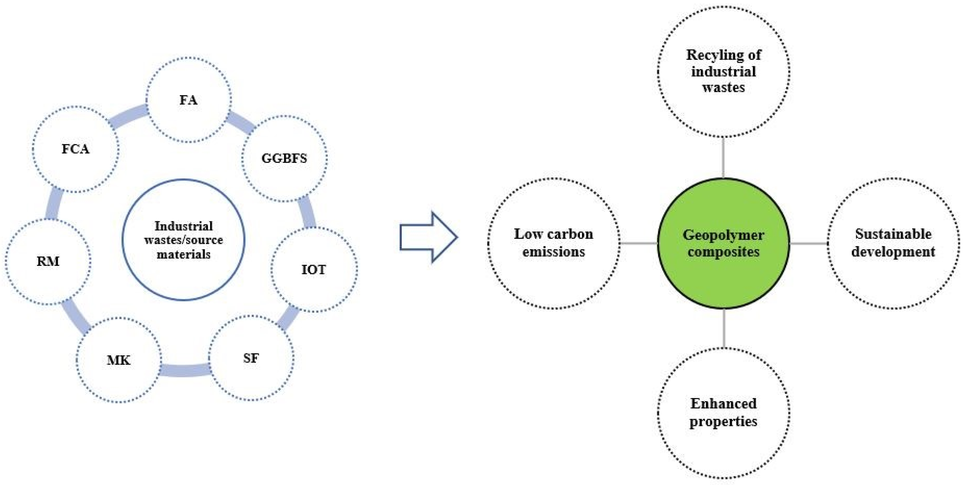
Figure 1. Utilization of industrial wastes for the production of geopolymer composites-leading to several merits.
Sustainability 14 15062 g001
Figure 2. The graphs show the distribution of SiO2, Al2O3, CaO, Fe2O3, MgO (Wt.%) in the industrial wastes [17,19,20,21,22,23,24,25,26,27,28].
Sustainability 14 15062 g002
Figure 3. 28-day compressive strength of the FA-GGBFS geopolymer paste [79]. Reprinted with permission from Ref. [79]. Copyright 2017 Elsevier.
Sustainability 14 15062 g003
Figure 4. Compressive strength of FA-GGBFS geopolymer mortars [73].
Sustainability 14 15062 g004
Figure 5. Compressive strength IOT-FA-based geopolymer [99]. Reprinted with permission from Ref. [99]. Copyright 2016 Elsevier.
Sustainability 14 15062 g005
Figure 6. Compressive strength of geopolymer with different metakaolin content before and after exposure to sodium sulfate solution [107]. Reprinted with permission from Ref. [107]. Copyright 2016 Elsevier.
Sustainability 14 15062 g006
Figure 7. Effects of fly ash content on compressive strength of geopolymers at 7 d and 28 d after curing at 25 °C [108]. Reprinted with permission from Ref. [108]. Copyright 2014 Elsevier.
Sustainability 14 15062 g007
Figure 8. Effect of SF on compressive strength [109]. Reprinted with permission from Ref. [109]. Copyright 2013 Springer Nature.
Sustainability 14 15062 g008
Figure 9. (a,b) XRD patterns of 100% FA-based samples [78].
Sustainability 14 15062 g009
Figure 10. XRD pattern of 100% FA-based samples [71]. Reprinted with permission from Ref. [71]. Copyright 2018 Elsevier.
Sustainability 14 15062 g010
Figure 11. (a,b) XRD patterns of 100% FA-based samples [111]. Reprinted with permission from Ref. [111]. Copyright 2021 Springer Nature.
Sustainability 14 15062 g011
Figure 12. XRD patterns of FA-GGBFS geopolymer specimens [112].
Sustainability 14 15062 g012
Figure 13. XRD patterns of FA-GGBFS-based geopolymer sample with 20% MK [113]. Reprinted with permission from Ref. [113]. Copyright 2021 Elsevier.
Sustainability 14 15062 g013
Figure 14. XRD pattern of the RM-FA geopolymer after exposure to elevated temperatures [116]. Reprinted with permission from Ref. [116]. Copyright 2019 Elsevier.
Sustainability 14 15062 g014
Figure 15. XRD spectra of RFFG samples cured at 80 °C; (Q: Quartz, M: Mullite, K: Kaolinite, Na: Nacrite, He: Hematite, and Ca: Calcite) [118]. Reprinted with permission from Ref. [118]. Copyright 2018 Elsevier.
Sustainability 14 15062 g015
Figure 16. XRD patterns of IOT-FA (30:70) based geopolymer sample [120]. Reprinted with permission from Ref. [120]. Copyright 2016 Elsevier.
Sustainability 14 15062 g016
Figure 17. XRD patterns of the geopolymer paste with 7 days of autogenous curing [121]. Reprinted with permission from Ref. [121]. Copyright 2017 Elsevier.
Sustainability 14 15062 g017
Figure 18. XRD patterns of fly ash geopolymers with varying silica fume contents [122].
Sustainability 14 15062 g018
Figure 19. (a,b) SEM images of 100% FA-based samples [118]. Reprinted with permission from Ref. [30]. Copyright 2018 Elsevier.
Sustainability 14 15062 g019
Figure 20. (a,b) SEM images of 100% FA-based samples [75]. Reprinted with permission from Ref. [75]. Copyright 2019 Elsevier.
Sustainability 14 15062 g020
Figure 21. SEM images of 100% FA-based samples [77]. Reprinted with permission from Ref. [77]. Copyright 2020 Elsevier.
Sustainability 14 15062 g021
Figure 22. SEM analysis of a 10% slag sample after 28 days of curing, 10,000 magnification [125]. Reprinted with permission from Ref. [125]. Copyright 2016 Elsevier.
Sustainability 14 15062 g022
Figure 23. SEM micrograph of Fly ash-GGBFS geopolymer [128]. Reprinted with permission from Ref. [128]. Copyright 2017 Elsevier.
Sustainability 14 15062 g023
Figure 24. SEM image of ambient cured paste (a) GRM30–6 M, (b) GRM50–6 M, (c) GRM30–10 M [129]. Reprinted with permission from Ref. [129]. Copyright 2018 Elsevier.
Sustainability 14 15062 g024
Figure 25. SEM image of RM-FA (30:70) based geopolymer sample [130].
Sustainability 14 15062 g025
Figure 26. SEM image of IOT-FA (a) Reference and (b) IOT20 (c) IOT20–7 thermal cycles 200 °C (d) reference–7 thermal cycles 200 °C [99]. Reprinted with permission from Ref. [99]. Copyright 2016 Elsevier.
Sustainability 14 15062 g026
Figure 27. SEM image of IOT-FA (a) Geopolymer (b) Porous geopolymer [120]. Reprinted with permission from Ref. [120]. Copyright 2016 Elsevier.
Sustainability 14 15062 g027
Figure 28. SEM images (a) Mix involving FCA and FA, (b) Mix involving FCA and FA (aggregate and binder phase) [106]. Reprinted with permission from Ref. [106]. Copyright 2022 Springer Nature.
Sustainability 14 15062 g028
Figure 29. SEM images of (a) GFA40-1 Day, (b) GFA40-7 Day, (c) GFA40-28 Day [108]. Reprinted with permission from Ref. [108]. Copyright 2014 Elsevier.
Sustainability 14 15062 g029
Figure 30. SEM micrographs of fly ash geopolymers with (a) 0 wt.%, (b) 2 wt.% and (c) 4 wt.% of silica fume [122].
Sustainability 14 15062 g030
Figure 31. FTIR Spectra of 100% FA-based samples [71]. Reprinted with permission from Ref. [71]. Copyright 2018 Elsevier.
Sustainability 14 15062 g031
Figure 32. (a,b) FTIR spectra of 100% FA-based samples [131].
Sustainability 14 15062 g032
Figure 33. FTIR spectra of 100% FA-based samples [132,133].
Sustainability 14 15062 g033
Figure 34. (a) FTIR spectra for FA and GGBFS (b) FTIR spectra for 28 day-cured FA-GGBFS based geopolymer samples [133]. Reprinted with permission from Ref. [133]. Copyright 2018 Elsevier.
Sustainability 14 15062 g034
Figure 35. FTIR of FA and BFS and geopolymer pastes with (a) 8 M NaOH solution and (b) 16 M NaOH solution [123].
Sustainability 14 15062 g035
Figure 36. FTIR spectra of RM-FA-based geopolymer pastes [140].
Sustainability 14 15062 g036
Figure 37. FTIR spectra of RM-FA (80:20) based geopolymer pastes [141]. Reprinted with permission from Ref. [141]. Copyright 2011 American Society of Civil Engineers.
Sustainability 14 15062 g037
Figure 38. FTIR spectra of FCA-FA geopolymer binder sample [106]. Reprinted with permission from Ref. [106]. Copyright 2022 Springer Nature.
Sustainability 14 15062 g038
Figure 39. FT-IR spectra of un-exposed fly ash geopolymers with varying silica fume content addition [122].
Sustainability 14 15062 g039
Table 1. Chemical compositions of FA, GGBFS, IOT, RM, and FCA; detected from XRF analysis.
Industrial Source & RegionAuthorsChemical Compositions (Wt.%)
SiO2Al2O3CaOFe2O3MgO
FLY ASHNTPC Ramagundam Thermal Power Plant, India[27]60.1126.534.004.251.25
Tarong Power Plant, Australia[28]75.6619.000.301.380.00
Gladstone Power Station, Australia[29]47.8328.495.5111.381.43
Cates Electrical Prod. Plant, Turkey[30]54.0826.0835.586.682.67
Lethabo Power Plant, South Africa[31]56.4530.274.593.581.06
GGBFSNippon Steel & Sumitomo
Metal Corporation, Japan
[32]30.5313.6746.000.335.09
Vizag steel plant, India[33]30.6116.2434.480.586.79
JSW Iron and Steel Plant, Bellary, India[34]32.5217.1434.221.229.65
Rourkela Steel Plant, India[35]30.8221.0632.021.379.52
Esfahan Steel Company, Iran[36]35.8513.3937.711.069.10
IOTLake Superior Iron Ore District facility, USA[37]68.770.86750.27528.170.74
Copper-iron mine, Zibo city, China[38]70.325.14.7110.934.51
Iron ore tailing dam, Brazil.[39]30.0021.200.1047.80-
Iron Ore mine site, Kuancheng Chengde, China[40]67.588.705.787.424.37
Iron ore tailings dam, Ouro Preto, Brazil.[41]40.008.700.0048.90-
RMRio Tinto Aluminium company, Canada[42]10.5222.121.3638.920.10
Hindalco Industries, Belgaum, India[43]9.9318.12.342.9-
Tan Rai Bauxite Plant, Vietnam[44]4.5218.980.8749.90-
Aluminium Smelter, Alcoa, Spain[45]5.6714.631.8852.253.35
Zhaofeng Aluminium Company, China[46]21.4322.7216.499.980.00
FCABalasore Alloys Limited, India[47]19.6011.24.26.115.6
Balasore Alloys Limited, India[48]19.1010.913.147.8423.60
Balasore Alloys Limited, India[24]19.1010.913.147.8423.60
MKCˇ LUZ (Nové Strašecí, Czech Republic)[49]55.0140.940.550.550.14
Astrra Chemicals, Chennai, India[50]47.6450.220.050.240.05
Hongle, Inc. (Henan, China).[25]53.6543.120.170.760.06
SFCounto Microfine Products Pvt.Ltd., Goa, India[15]93.670.830.311.300.84
Shenhua Junggar Energy
Corporation, Junggar, China
[51]95.720.090.230.630.37
SMS ASIA Pvt. Ltd., Rourkela,
India
[26]93.670.830.311.300.84
Table 2. Compressive strength of FA-based geopolymer binders.
AuthorsSpecimen TypeSource MaterialsMolarity of NaOHCuring Regime28-Day Compressive Strength (Mpa)
[71]Paste100% FA12 MOven
(60 °C + 48 h)
N/A
[73]Mortar100% FA14 MAmbient41.3
Oven
(30 °C + 18 h)
50
Oven
(60 °C + 18 h)
63
[30]Mortar100% FA12 MOven
(80 °C + 24 h)
60.45
[74]Concrete100% FA 12 MOven
(60 °C + 48 h)
N/A
100% FA N/A
[75]Concrete100% FA 12 MOven
(75 °C + 24 h)
26.1
100% FA 14
100% FA 13.7
[76]Mortar100% FA10 MOven
(60 °C + 48 h)
34.3
[72]Concrete100% FA 8 MAmbient30.7
[77]Mortar100% FA 10 MOven
(60 °C + 48 h)
N/A
[78]Mortar100% FA4 MOven
(60 °C + 24 h)
8.18
Table 3. Compressive strength of FA-GGBFS-based geopolymer binders.
AuthorsSpecimen TypeSource MaterialsMolarity of NaOHCuring Regime28-Day Compressive Strength (MPa)
[80]Concrete50% FA + 50% GGBFS8Ambient temperature41
[81]Concrete70% FA + 30% GGBFS8Room temperature45
[82]Concrete60% FA+ 40% GGBFS16Ambient temperature 49.53
[83]Concrete80% FA + 20% GGBFS6Ambient temperature38
[84]Concrete70% FA + 30% GGBFS8Oven 41.26
[85] 62% FA + 38% GGBFS10Ambient temperature39.9
[86]Concrete50% FA + 50% GGBFS8Oven 60 °C 24 h61.9
[87]Concrete80% FA + 20% GGBFS1020 °C in sealed containers (>90% relative humidity, RH)39
[88]Concrete90% FA + 10% GGBFS10Oven 60 °C 24 h45.62
[89]Concrete20% FA+ 80% GGBFS12Oven 80 °C 24 h21.35
[78]Mortar50% FA + 50% GGBFS4Ambient temperature42
[72]Concrete70% FA + 30% GGBFS8Ambient temperature42.2
[75]Concrete70% FA + 30% GGBFS1275 °C + Ambient temperature52.3
[74]Concrete70% FA + 30% GGBFS12Oven 60 °C + Ambient temperature47.2
Table 4. FA-RM-based geopolymer binders.
AuthorsSpecimen TypeSource MaterialsMolarity of NaOHCuring Regime28-Day Compressive Strength (MPa)
[93]Concrete15% RM + 15% FA8Ambient
temperature
38
[94]Paste20 RM + 80% FA12.5Oven
35 °C 48 h
64
[95]Paste50 RM + 50% FA8Autoclave31.7
[96]Paste5% RM + 95% FA6Oven
60 °C 24 h
41.38
[97]Mortar40% RM + 60% FA10Ambient temperature13.49
Table 5. XRD peaks of geopolymers with different binder compositions.
Binder CompositionXRD PeaksReference
FA (100%)Quartz, Magnetite, Mullite, Arghonite, Calcite, Albite, Hydrosodalite[78]
FA (100%)Calcite, Quartz[71]
FA (100%)Quartz, Mullite[111]
FA (70%)-GGBFS (30%)Quartz, Mullite[112]
FA (50%)-GGBFS (50%)Quartz, Anorthite, Etringite, Calcite, Albite, Mullite, Hydrotalcite[123]
FA (80%)-RM (20%)Quartz, Mullite[116]
FA (80%)-RM (20%) (800–1000 °C)Quartz, Mullite, Nepheline[116]
FA (80%)-RM (20%)Quartz, Mullite, Kaolinite[118]
FA (70%)-IOT (30%)Quartz, Mullite, Anatase[120]
IOT (100%)Quartz, Sodian, Goethite, Birnessite[22]
FCA (60%)-FA (40%) Quartz, forsterite, K- feldspar mineral donathite, silvine[24,48,106]
FA (30%)-MK (70%)Mullite, Quartz, Kaolinite[121]
FA (98%)-SF (2%)Quartz, Mullite, Hematite, Zeolite[122]
Table 6. FTIR bands of geopolymers with different binder compositions.
Binder CompositionFTIR Bands (cm−1)Reference
FA450, 1050, 1450, 1650, 3450[71]
FA (100%)559.3, 873.6, 962.3, 1421, 1640, 3375[140]
FA (100%)983, 1522, 1659, 2346, 3377, 3633[122]
FA (50%)-GGBFS (50%)580–780, 997, 1650, 3420[123]
FA (30%)-GGBFS (50%)-MK (20%)495, 1170, 1510, 1660, 3600[113]
FA (70%)-RM (30%)612.3, 670.1, 957.5, 1100, 1415, 1641, 3384[140]
FA (20%)-RM (80%)452.69, 720.98, 991.66, 1453.8, 1644.56, 3441.59[141]
FCA (60%)-FA (40%)447, 458, 484, 600, 1007, 1430–50, 1650, 3440[106]
FA (98%)-SF (2%)986, 1521, 1660, 2343, 3376, 3643[122]
FA (96%)-SF (4%)990, 1520, 1660, 2346, 3383, 3632[122]
Table 7. Types and specifications of instruments used in microstructure characterization.
Binder SystemSpecimen TypeAnalysis TypeInstrumentSpecificationsReferences
FA (100%)PasteSEMThermoscientific ApreoSSize (10 µm–20 µm)[111]
EDXOxford Instruments INCA
XRDRigaku, D/max-2400Test range (5°−85°), Scanning speed (10°/min)
FTIRNicolet, NEXUS 670
BETMicromertics, Inc., Trister 3020/ASAP2020M
29Si NMRBruker AVANCE III 600M
Unconfined Compressive StrengthTDW-10-300Loading rate (2400 N/s ± 200 N/s)
XRDMalvern Panalytical, EMPYREANCu-Ka radiation, 2θ values of 10–90[142]
FTIRBruker, TENSOR 27Wavenumbers (600–4000 cm−1), Transmission mode
Vibrating Specimen Magnetometer (VSM)Quantum Design, Inc., VersaLabTMMagnetic field range of −10 kOe to 10 kOe at room temperature (25 °C)
MortarSEMJWEL JSM 6360AMagnification (5000×–15,000×), Size (1 µm–5 µm)[132]
FTIRJasco-6100Absorption mode up to 4000 cm−1
XRDPhilips PW 1390 DiffractometerScanning speed (2°/min)
Micro-Computed Tomography (CT)Newton 5G System110 kV microfocus X-ray source[30]
Thermal ConductivityISOMET2114 [77]
XRDD/Max-2200 Ultima/PC2θ (5° to 100°)[78]
SEM-EDXLYRA3 XMUSpecimens coated with Platinum
ConcreteSEM-EDXEVO 18LaB6 filaments electron source[72]
Thermal conductivityISOMET2114ASTM D5930-17[143]
FTIRVarian 3100 FT-IR SpectrometerTransmittance mode (400 to 4000 cm−1), Resolution (1 cm−1)[131]
SEMJEOL-JSM 6390AHigh-Vacuum SEM mode and Energy-Dispersive X-ray analysis
DSCDSC Q200Heating rate of 10 °C/min, Constant flow of nitrogen gas (50 mL/min)
SEM-EDXLYRA3 XMUSpecimens coated with Platinum
SEM-EDXJEOL JSM-6010PLUSAccelerated voltage (15 kV)
FA-GGBFSPasteXRDBruker AXS D22θ (10–65°), Cu Kα X-ray source[112]
TGADTA-TG (DTG-60H)Heating rate of 10 °C/min from room temperature to 1000 °C
27Al and 29Si NMR AnalysisBruker 400 MHz Avance III NMR spectrometer
Optical MicroscopeStemi 508Monitor cracking in samples[144]
XRDD8 DiffractometerVoltage of 40 KV using CuKa radiation, 2θ scanning range of 5°–50°[145]
SEM/EDXCOXEMEM-30PLUSMagnification (2 kx–20 kx)
FESEMOxford, Carl ZeissMagnification (1000 kx)
XRDRigaku Mini-flex 600Broad-angle measurement (5–130°) 2θ[113]
FTIRJASCO FT///IR-6300Wavelength range (400 to 4000 cm−1)
FTIRJASCO FT///IR-6300wavelength range (400 to 4000 cm−1)
FA-RMPasteXRDPanalytical EmpyreanElemental composition[91]
Hydration HeatI-Cal 8000Heat of geopolymer reaction
SEMGeminiSEM
Electron Microprobe (EMP)Cameca SX-
100
Raw Materials composition
XRDRigaku GeigerflexCr Kα radiation, Voltage
(37.5 kV), Current (25 mA)
SEMJEOL JSM-7000FSecondary electron mode[116]
FTIRBruker Optics Vetex70Transmittance mode (500–1600 cm−1), Resolution (2 cm−1)
XRDPANalytical B. VCu Kα radiation, 40 mA, 40 kV
XPSAxis-Ultra Dld-600 WAl Kα radiation, 10 mA, 15 kV[12]
Mössbauer SpectroscopyTopologic 500AProportional
Counter attachment
FTIRBruker Vetex70Wavenumber range of (450–4000 cm−1)
SEMFEI, Sirion 200 High vacuum mode, Acceleration voltage (10 kV)
Thermogravimetric Analysis (TGA)NETZSCH STA 409 PCHeated in nitrogen atmosphere from 25 °C to 1000 °C at 5 °C/min
FA-IOTPasteSEM/Energy Dispersive X-ray Spectroscopy (EDX)JSM-5610LVAccelerating voltage of 15 kV[99]
SEMZeiss SUPRA 55-VP FEG-SEMoperated at 15 kV and having resolution capacity of 1–4 nm.
FA-FCA XRDDiffractometer2θ value was kept in a range of 10–90°and the scanning rate at 2.4° per minute[106]
FTIRPerkinElmer Spectrum GX FTIR spectrometer-
PetrographyOptical microscope (Laica made)set to view under 20× to 50× magnification
SEMA ZEISS EVO MA18-
FA-MK XRDThermo ARL9900 machineCo Ka radiation, with a scanning rate of 2.4/min from 8 to 80 2 h[107]
SEMJEOL JSM-6460 LAMagnification of 500 & 1000×
FA-SF XRDShimadzu X-ray Diffractometer
(XRD-6000)
-[120]
FTIRPerkinElmer FTIR spectrometerscanned from 650 cm−1 to 4000 cm−1 with a resolution of 4 cm−1
Publisher’s Note: MDPI stays neutral with regard to jurisdictional claims in published maps and institutional affiliations.