Article

Design and Practice of Deep Foundation Pits for Large Storage Ponds in Complex Environments

1
Fuzhou Planning & Design Research Institute Group Co., Ltd., Fuzhou 350108, China
2
Zijin School of Geology and Mining, Fuzhou University, Fuzhou 350108, China
*
Author to whom correspondence should be addressed.
Sustainability 2022, 14(21), 14046; https://doi.org/10.3390/su142114046
Submission received: 8 September 2022 / Revised: 23 October 2022 / Accepted: 25 October 2022 / Published: 28 October 2022

Abstract

:
Storage ponds (storm detention ponds) are an important part of sponge city construction, and the construction process involves deep and large pit excavation in a complex and sensitive environment. Combined with a large storage pond pit engineering design and practice process, in this study, the complex environment of the design of the large storage pond pit method has been explored, using the field measurement data to test the support design of the deformation control effect and to summarize the practice of the key, difficult points of treatment measures. The results show that the procedure adopted in this project is a successful practice for using the pit characteristics, and the special treatment carried out for addressing the difficult points can effectively control the deformation, thus achieving waterproofing and deformation requirements of large-capacity water storage ponds. The design of the support is very effective in controlling the duration and deformation. The cover-cut excavation method, in combination with the support system, is highly effective in deformation control, whereas the open-cut excavation method is more likely to shorten the duration. However, there is an uncertainty in the deformation control during the removal of temporary structures in this method. The deformation characteristics of the pit enclosure and the surrounding ground surface are within the design requirements. The horizontal displacement of the wall and the surrounding settlement are mainly developed during the stage of dismantling the temporary support structure after excavating the first basement level and during the construction of the first and second slabs. The other stages benefit from the strong integrity of the support system, which can efficiently control the deformation. The treatment measures, support types, and component connection methods summarized in this article can provide a reference for the construction of similar underground storage ponds.

1. Introduction

With the acceleration of urbanization, the proportion of hardened roads in cities has increased, and the flow of urban sewage runoff has been increasing, leading to frequent urban flooding disasters [1,2,3]. For example, the “7.21” Beijing super heavy rainstorm in 2012 [4], the “7.6” rainstorm in Wuhan in 2016 [5], the “5.22” heavy rainstorm in Guangzhou in 2020 [6], and the heavy regional rainstorm in July 2021, in Zhengzhou, Henan Province [7] have caused serious urban flooding disasters, resulting in a large number of casualties, economic losses, and social impacts. As a modern drainage protection system, the storage pond can efficiently improve the capacity of the regional drainage system, eliminate the occurrence of waterlogging during the flood season, solve the problem of waterlogging during heavy rainfall, and ensure the safety of the regional flood control and drainage system. In addition, it can take into account the control of surface pollution, reduce the pollutants discharged into the river, and improve the ecological environment of water; thus, achieving the dual objectives of improving the quality of the water environment and increasing the risk resistance of the drainage system [8,9]. It is thus an important initiative to implement the concept of sponge city construction [10,11].
Nevertheless, the construction of a storage pond is bound to involve excavation of deep and large foundation pits, and it is very difficult to deal with an urban deep foundation pit adjacent to sensitive buildings surrounded by pipelines whose support design requires high deformation control and many complex factors that need to be considered. In recent years, many scholars have demonstrated many successful cases in terms of the design of the foundation pit support under such complicated conditions and have also performed extensive research on the stress, strain, and displacement changes caused by excavation [12,13,14,15,16]. This has led to the accumulation of rich experience in deep foundation pit excavation, which is becoming increasingly deep [17]. The excavation depth of many foundation pits in China is more than 30 m, such as the Shanghai World Expo Substation 34 m Foundation Pit [18], the Shanghai Dongjiadu restoration project pit of up to 41 m [19], etc. Unfortunately, these results are mostly concentrated in large underground spaces, large transportation hubs as the representative of the urban underground space, and the construction of super high-rise buildings. Most of the underground space is used for human engineering and living activities. It is rare to see the development of a large storage pond pit project in a city, and waterproof deformation control requirements of the city storage pool construction have not become a system yet.
However, it should be noted that deep foundation excavations in complex environments inevitably cause additional deformation and even damage to the adjacent tunnels, pipelines, and buildings, as does the deformation caused by the excavation of a large storage pond pit [20]. It can be seen that a reasonable construction process for a foundation pit project is important to reduce and control the additional deformation caused by the excavation and to guarantee the safety and stability of the project, as stated by Feng et al. [21,22,23]. According to the field measurement data, to analyze the deformation development law of the pit, these researchers have undeniably obtained many valuable conclusions to improve the understanding of the development of stress, strain, and displacement changes in the excavation process, which can also be used as a reference for excavating a pit for a deep, large storage pond.
Therefore, this study takes a large storage pond project as an example, introduces its design and practice, and based on field measurement data for testing the deformation control effect of the implementation process of the pit, summarizes the key points in the engineering practice, and measures for problems that are difficult to deal with, with a view for providing new design ideas for the design and practice of similar storage pond projects.

2. Project Overview

The proposed excavation pit is an irregular rectangle that is approximately 130 m long and 89.8 m wide, with a perimeter of about 412 m and an excavation depth of 22.7 m. It is used as an underground component of the comprehensive renovation project of the storage pond and as a three-dimensional parking lot, with an underground negative floor for social vehicle parking, negative two to negative five underground floors for the storage pond, and five floors above the ground for the three-dimensional bus parking building. In particular, the four-floor underground storage pool, having a volume of up to 160,000 m3, is the first single domestic construction of a storage pond with the largest capacity in China. After its completion, it can treat the accumulated water in the surrounding 0.46 km2 area.
The foundation pit is located in the center of Fuzhou City, China, which has a low-lying terrain and is thus prone to flooding during heavy rain. Further, as presented in Figure 1, it is surrounded by deformation-sensitive buildings, with a gas filling station (1 floor (1F), shallow foundation) that is approximately 14 m to the east, a residential building (7F) that is approximately 6 m to the west, a dormitory (7F) that is approximately 33 m to the south, and an office building (3F, shallow foundation) that is approximately 7 m to the north, and the location has a limited construction space. The excavation area contains weak soil layers with poor geological conditions. The representative parameters of the different soil layers and the thickness of each layer are given in Table 1. The groundwater at the site is shallow, mainly consisting of an upper layer of stagnant water with a stable water table depth of 0.50 to 2.60 m, pressurized water in gravelly sand (head depth of approximately 3.0 m), and pore–fissure water in weathered rock.

3. Foundation Excavation Design Plan

3.1. Foundation Pit Support System

3.1.1. Enclosure Structure

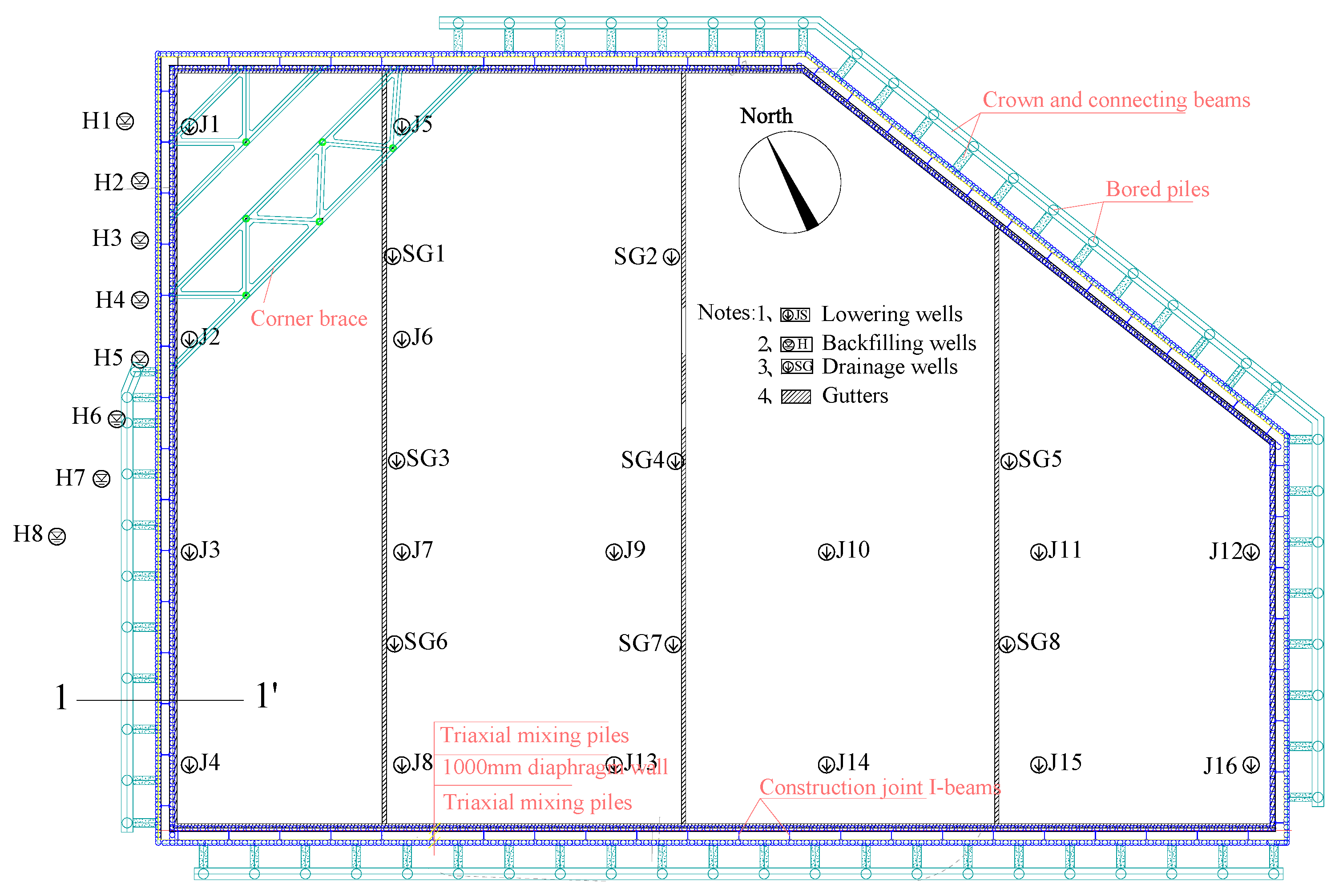
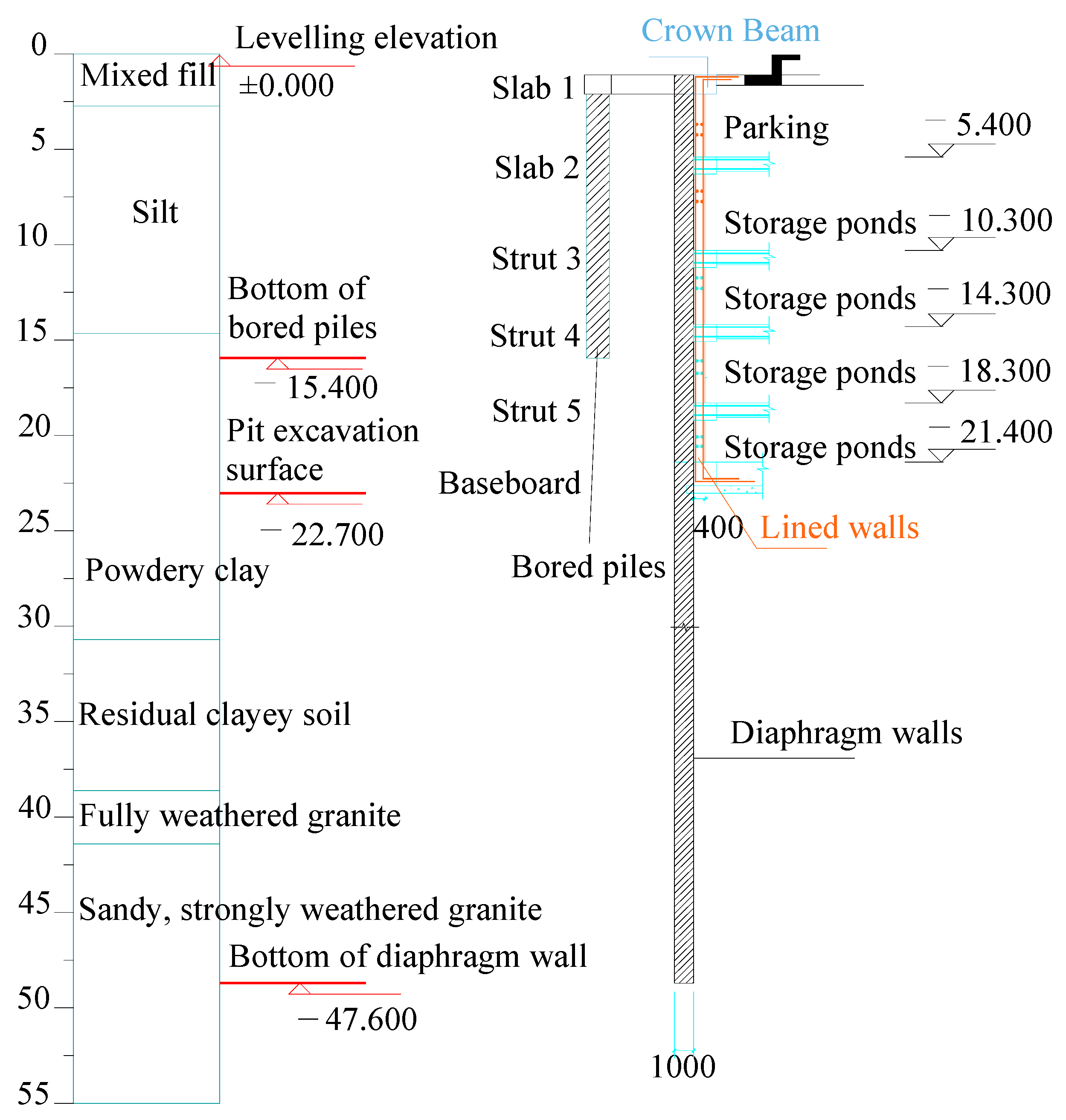
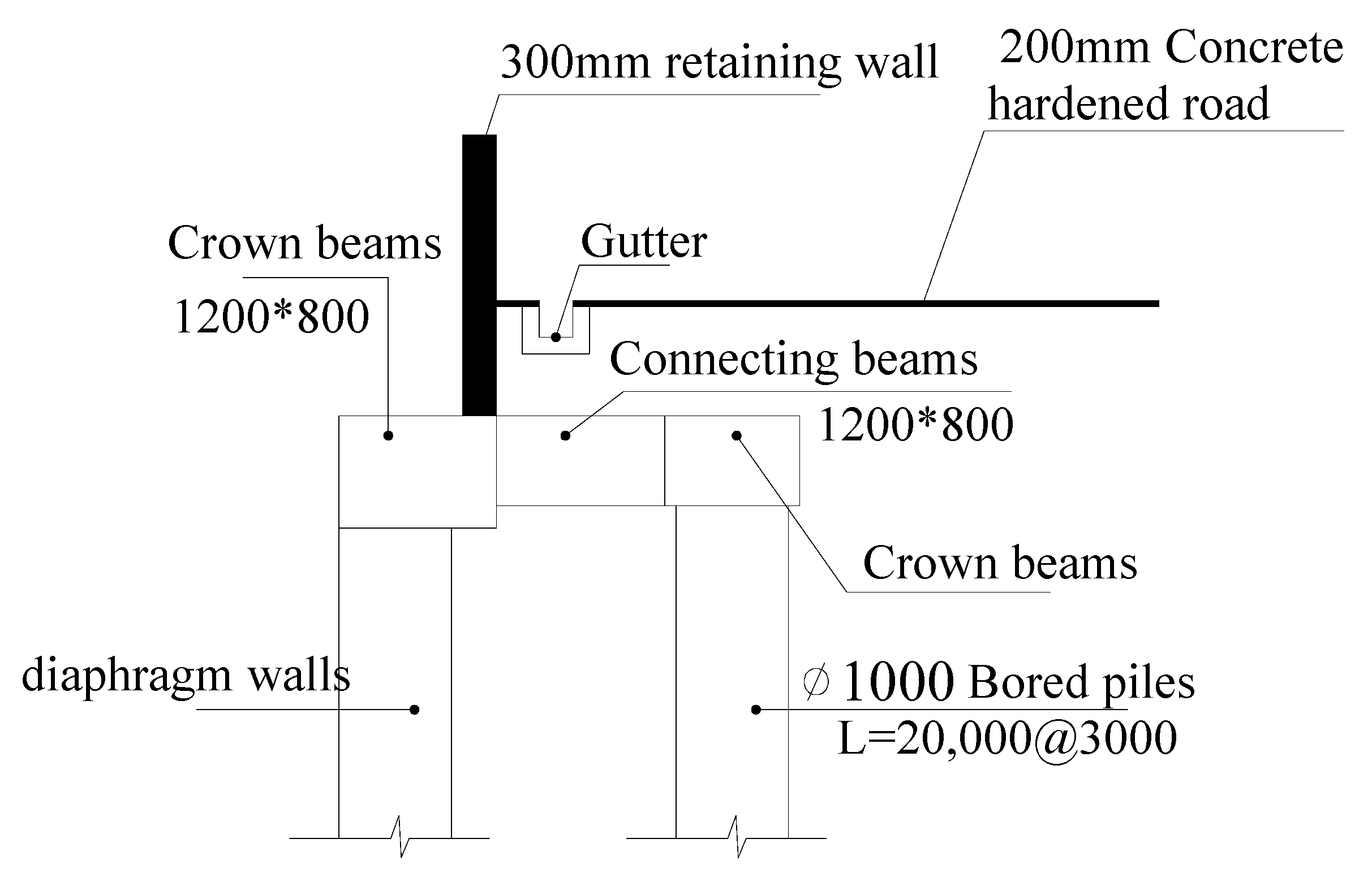
The construction space available around the pit was limited, the excavation depth was deep, the surrounding environment was complex, and the hydrogeological conditions were poor. In addition, the construction plan had a tight schedule and budget, and the pit had high requirements for back seepage and deformation control. In order to ensure the safety, economy, and construction rate of the project, the underground diaphragm wall support, commonly used in subways, was introduced in the design of the foundation pit support system, with a diaphragm wall thickness of 1.0 m and depth of 47.6 m, which improved the stiffness of the support while ensuring good water stopping effect. The combination form of supporting two beam slabs (the top slab and bottom slab of the negative layer also serve as the support structure) and three structural beams (also serving as the permanent structural beams of the 4-story storage pond) was adopted. The combination form of φ650 × 25 mm steel pipe concrete pile (which also serves as a permanent structure column) was used as the vertical support system. In particular, at the top of the pit, φ1200@6000 mm bored piles were set 4.5 m outside the diaphragm wall. A 1200 mm × 800 mm crown beam was set at the top of the pile, whereas a 1200 mm × 800 mm contact beam was used to connect with the underground diaphragm wall. The northwest corner was constrained by the adjacent building, and thus a reinforced concrete corner bracing was used instead of double-row piles. The layout of the double-row pile and local corner brace is shown in Figure 2. The corresponding Figure 3 shows the schematic of a 1–1′ typical section enclosure structure.
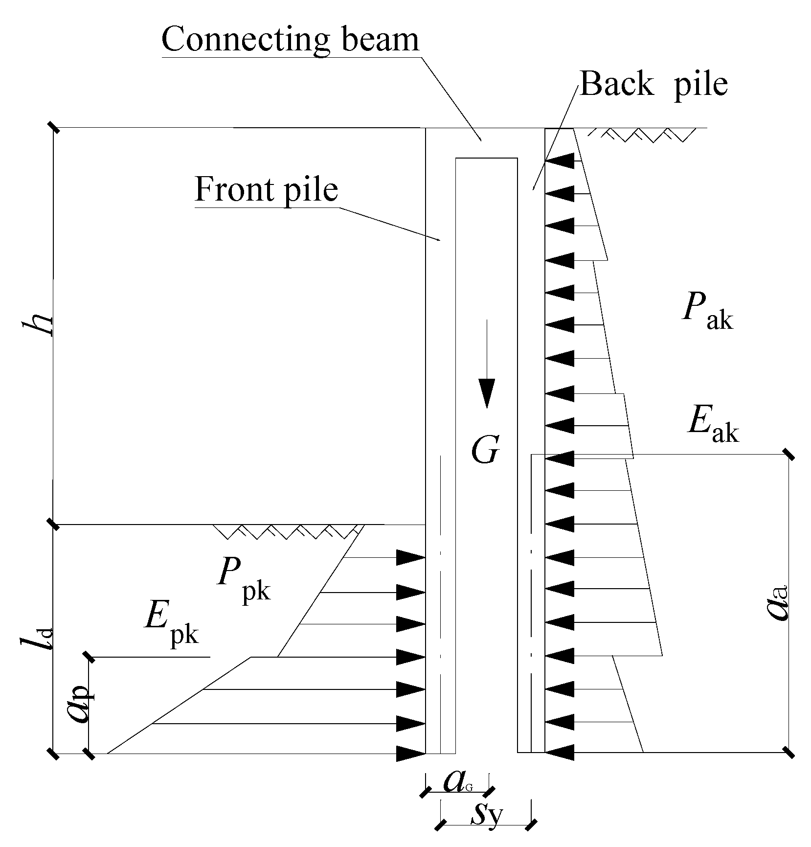
Especially, in contrast to the single-row piles, in the overturning stability test of the double-row piles, the double-row piles and the soil between the piles should be considered as a whole and as the object of the force equilibrium analysis. In addition, the overturning resistance of the soil and the self-weight of the piles should also be considered. Specifically, this should be calculated in accordance with Figure 4 and in accordance with the provisions of Equation (1). According to the calculation, the embedded depth, ld = 24.9 m, can satisfy the foundation stability requirements.
E pk a p + G a G E ak a a K e
where Ke is the embedded stability safety factor, and its value for this project could not be less than 1.25. Eak and Epk are the active soil pressure outside the pit and the standard value of the passive soil pressure inside the pit (kN), respectively. Aa and ap are the active soil pressure outside the pit and the passive soil pressure inside the pit, respectively, combined with the force point to the bottom of the double-row pile distance (m). G is the sum of the self-weight of the double row pile, tie beams, and the soil between the piles (kN); aG is the horizontal distance from the gravity center of the double row pile, tie beams, and inter-pile soils to the edge of the front row of piles (m).

3.1.2. Trough Wall Reinforcement

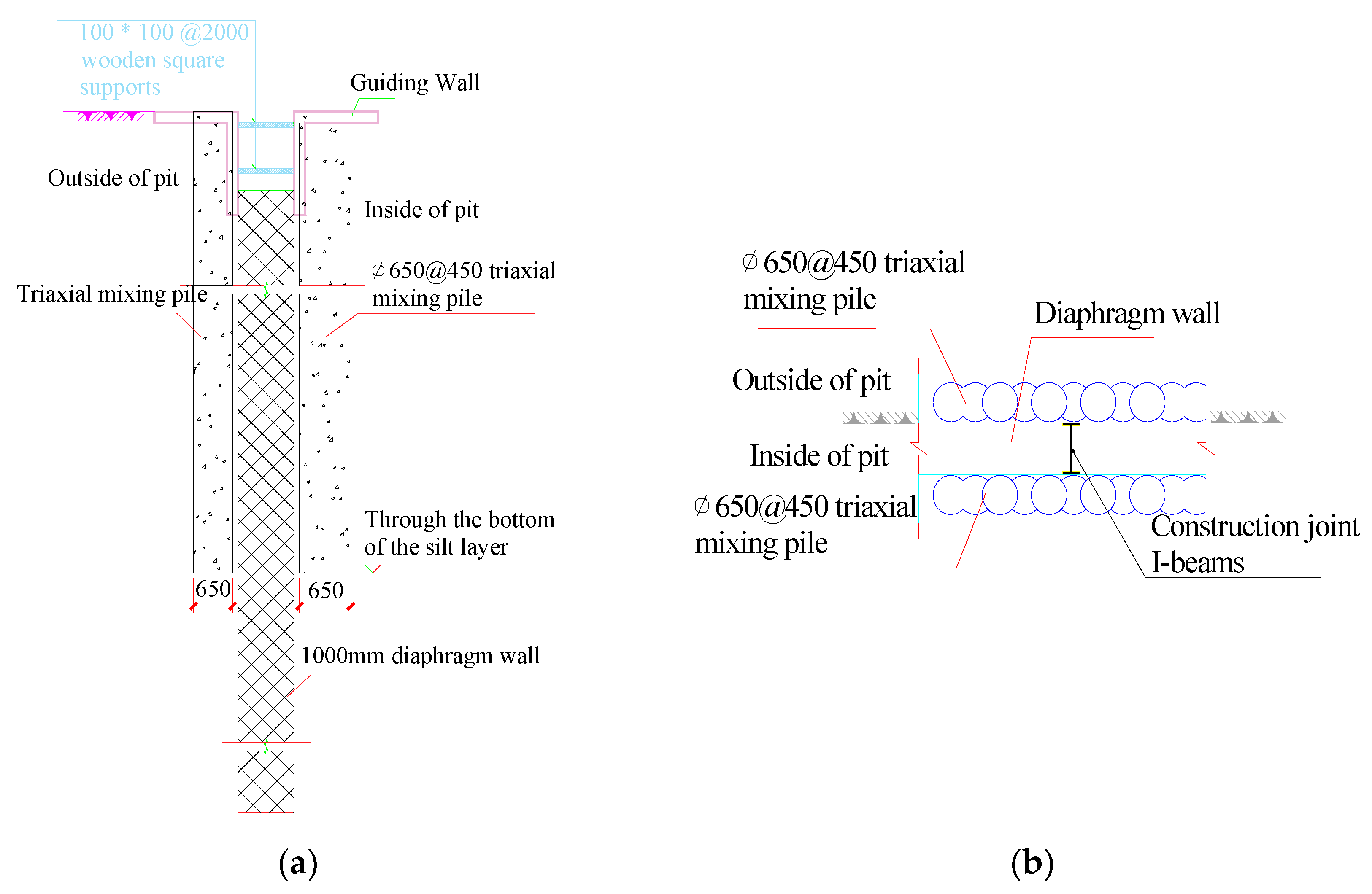
In order to prevent the diaphragm wall from collapsing in the process of forming the trench and affecting the neighboring sensitive buildings, pre-reinforcement was carried out on both sides of the trench wall by adding φ650@450 triaxial soil and water mixing piles with a depth of 14.3–16.3 m to enhance the stability of the underground continuous trench wall and improve the water stopping performance of the enclosure structure. Figure 5 shows a schematic of the trench wall reinforcement section.

3.1.3. Stacked Wall Design

The interior of the diaphragm wall was designed with a laminated wall by adding a layer of reinforced concrete liner wall, which was jointly stressed with the diaphragm wall. This helped in improving the waterproofing of the basement and achieved the requirements of using large-capacity water storage in storage ponds after completion. The thickness of the liner wall was pre-set to 400 mm, and it was necessary to prevent segregation and construction joints during construction to ensure the water storage performance of the basement.

3.2. Excavation Method

The construction process of the foundation pit combined the open-cut excavation method and the cover-cut excavation method to give full play to their respective advantages. The excavation depth of the first basement level was shallow, and the deformation was easy to control. Thus, the excavation rate was fast using the open-cut excavation method, which could shorten the construction period. On the other hand, the reverse method of cover-cut excavation was used for the second to fifth basement level excavation since it could solve the problem of the restricted space of the site and simultaneously and also ensure the economy and excavation efficiency of the project. The specific construction sequence is shown in Table 2.
Further, to improve the excavation efficiency and coordinate the progress of the project, the stiffness of the upper two slabs and vertical underground continuous beams was also reasonably designed to leave sufficient space for the plane spacing of the lower three support beams in order to design a larger column spacing. In particular, the implementation of the reverse method of cover-cut excavation also created conditions for the superstructure and underground excavation, saving the construction period.

3.3. Precipitation, Water Stop, and Recharge Design

This project adopted an underground diaphragm wall as the foundation pit enclosure, which also served as a water stop curtain to retain the soil and stop the water. The in-pit dewatering wells and out-pit recharge wells for groundwater control ensured smooth excavation of the foundation pit and reduced the impact of the foundation pit precipitation on the surrounding environment. Specifically, the total amount of water in the pit, single well discharge, etc. were calculated using the standard method, i.e., Equations (2) and (3), to achieve the purpose of controlling the precipitation in the negative first to negative fifth floors of the pit to 1.0 m below the working face and the bottom slab to 2.0 m below this slab. According to the calculation results, 16 φ400 mm dry wells (25 m spacing) were arranged in the pit of the foundation pit, and eight φ220 mm recharge wells (7 m spacing) were arranged outside the pit near the deformation-sensitive buildings. The specific layout of the precipitation wells is shown in Figure 2.
Q = π k ( 2 H 0 M ) M h 2 ln ( 1 + R r 0 )
q 0 = 120 π r s l k 3
where Q is the total influx of precipitation in the pit (m3/d), k is the infiltration coefficient (m/d), H0 is the initial head of the pressurized water aquifer (m), M is the thickness of the pressurized water aquifer (m), h is the water level height in the pit after precipitation (m), q0 is the single well discharge capacity (m3/d), R is the radius of precipitation influence (m), r0 is the equivalent radius of the pit (m), which can be calculated according to r 0 = A / π , rs is the filter radius (m), l is the length of the inlet portion of the filter (m), and A is the area of the pit (m2).
In addition, considering the high groundwater level of the project and the severe waterlogging in the urban area, the construction of the foundation pit during the flooding season was also a serious challenge. Therefore, to ensure the safety of the pit during the flooding period, a concrete retaining wall with a height of 2500 mm was installed at the top of the crown beam of the diaphragm wall to block the surface water from entering the pit, and 200 mm thick concrete was poured at one time after backfilling the surface of the tie beam to serve as a construction hardening road (as shown in Figure 6). Brick drainage ditches and catchment wells were also required outside the pit to remove the surface water. Thus, temporary drainage ditches and several water-collection wells in the pit were made, and the water in them was pumped by submersible pumps. As the excavation depth increased, the open ditch and catchment wells were deepened accordingly, and the pumped water was discharged to the open ditch outside the pit to the municipal sewer after settling in the catchment wells.
It should be noted that the precipitation process needs to ensure that 80% of the pumped water can be recharged to the bottom layer outside the pit through the recharge well. In addition, the change of the groundwater level outside the pit was required to be observed regularly every day through the observation well outside the pit to avoid the water level outside being too low and causing deformation of the surrounding buildings and structures.

3.4. Monitoring System

In order to fully grasp the deformation of the pit itself and its influence on the surrounding environment during construction, the dynamic monitoring items of this pit included: horizontal and vertical displacement at the top of the diaphragm wall, deep horizontal displacement, deformation of the surrounding buildings, support stress, monitoring of the soil pressure behind the wall, monitoring of the uplift of the pit bottom, monitoring of the pore water pressure, etc. Figure 7 shows the monitoring plan layout. In particular, the monitoring system adopted a “three-stage warning”, which set three powerful lines of defense for the safety of the foundation pit and the surrounding buildings, with yellow, orange, and red warning values, respectively (as shown in Table 3). In addition, targeted contingency measures were formulated for the different stages of warning to prevent minor problems and create a safe and reliable construction environment, providing a reliable parameter basis for the smooth construction and design optimization of this project.

4. Foundation Pit Project Implementation and Monitoring

4.1. Specific Implementation

The foundation pit project involves the process, technology, management, environment, hydrology, and other issues and is a system project with strong integration of theory and practice. In selecting the foundation support structure, safety and reliability were considered as the core, the feasibility of the applied technology and construction was considered first, and based on this, an economical and reasonable design solution with little impact on the environment was chosen. A construction organization and design plan were developed to satisfy the requirements of the project, and equipment, personnel, and construction space were properly deployed for the project.
The entire basement construction lasted only 14 months, from the start of construction in April 2017 to the completion of the main structure acceptance of the basement in June 2018. Further, the aforementioned pit support design program during construction experienced the test of waterlogging in the surrounding areas during the flood season and even several typhoons. The support structure and the surrounding sensitive building deformation were also controlled within the safe range. More importantly, the underground storage pond was operated without any leakage problem, which also verifies the reasonableness of the support design scheme.

4.2. Analysis of the Monitoring Results

The deployment of the monitoring system during the construction of the foundation pit was used to monitor the force and deformation characteristics of the enclosure structure and the support system in real time and grasp the settlement and tilt characteristics of the surrounding sensitive buildings. The monitoring results show that the monitoring data of the entire process of pit construction are within the control range of the specification, the support system is always in a safe and stable state, and the influence of pit excavation and unloading on the surrounding sensitive buildings also fully conforms to the requirements of the relevant regulations. This confirms the positive effects of the abovementioned pit excavation method in such projects. More specifically, it can be described in detail in terms of the following points.

4.2.1. Displacement Characteristics of the Diaphragm Walls

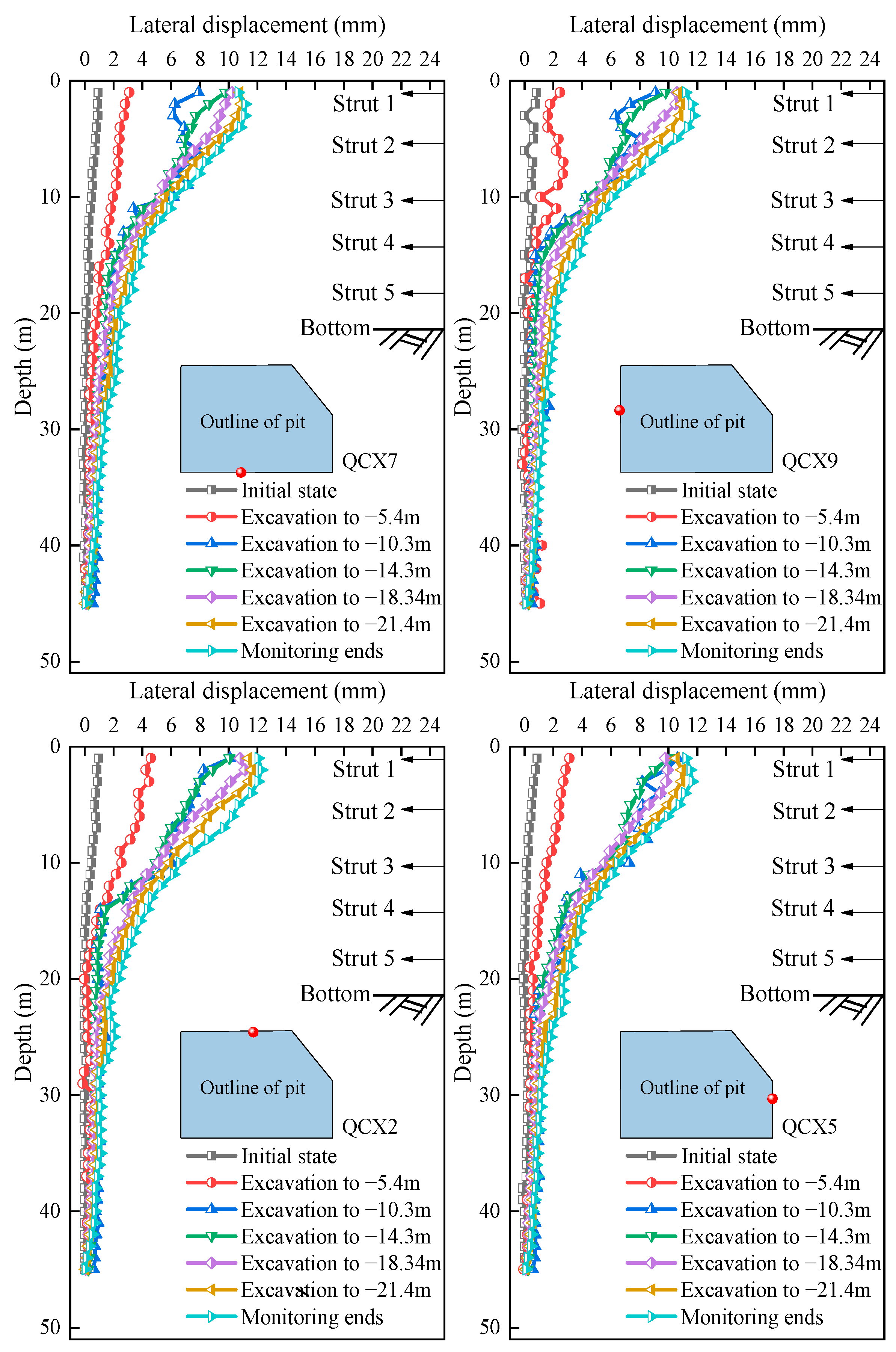
Figure 8 shows the horizontal displacement curves of the diaphragm wall at four typical measurement points, QCX2, 5, 7, and 9, in the different excavation stages. It is obvious that the deformation law of each measurement point is identical, and the horizontal displacement is within 15 mm of the yellow warning range. As the excavation depth of the foundation pit increases, the horizontal displacement of each measurement point also gradually increases, but the displacement increment is mainly concentrated at the end of the excavation of the first to the second basement and accounts for approximately 50% of the maximum lateral displacement, whereas the rest of the stage is very small. This is closely related to the removal of the temporary support structure and the construction of the first and second slabs after the end of the excavation. In particular, the excavation of the first basement level was a typical open excavation method with fast excavation speed, short excavation time, and temporary support structure, and thus the horizontal displacement changes are small. However, before the excavation of the second basement level, the removal of the temporary support structure of the first basement level and the construction of the slab took a long time, with an accumulated time of up to 3 months, the foundation pit was exposed for a long time, and the enclosure structure had a long unsupported period. Coupled with the fact that the negative two layers of soil are mainly silt with poor physical properties that exhibit significant rheological characteristics, significant horizontal displacement increments were accumulated due to the combined effect of time. In addition, benefits were achieved from the implementation of the inverse method of cover-cut excavation and two slabs + three structural beams, due to which the soil excavation of the remaining three layers and the deformation of the enclosure wall were efficiently controlled. This shows that the use of the cover-cut excavation method, with large rigidity slabs as the horizontal support, has a significant effect on the restraint of the horizontal displacement of the enclosure structure. The maximum lateral displacement mainly occurs in the gap period before the first and second slabs are poured, which also confirms the superiority of the cover-cut excavation method in the aforementioned support design scheme. Thus, this method can significantly reduce the deformation of the foundation pit and ensure the safety and stability of the foundation pit as well as the surrounding sensitive buildings.
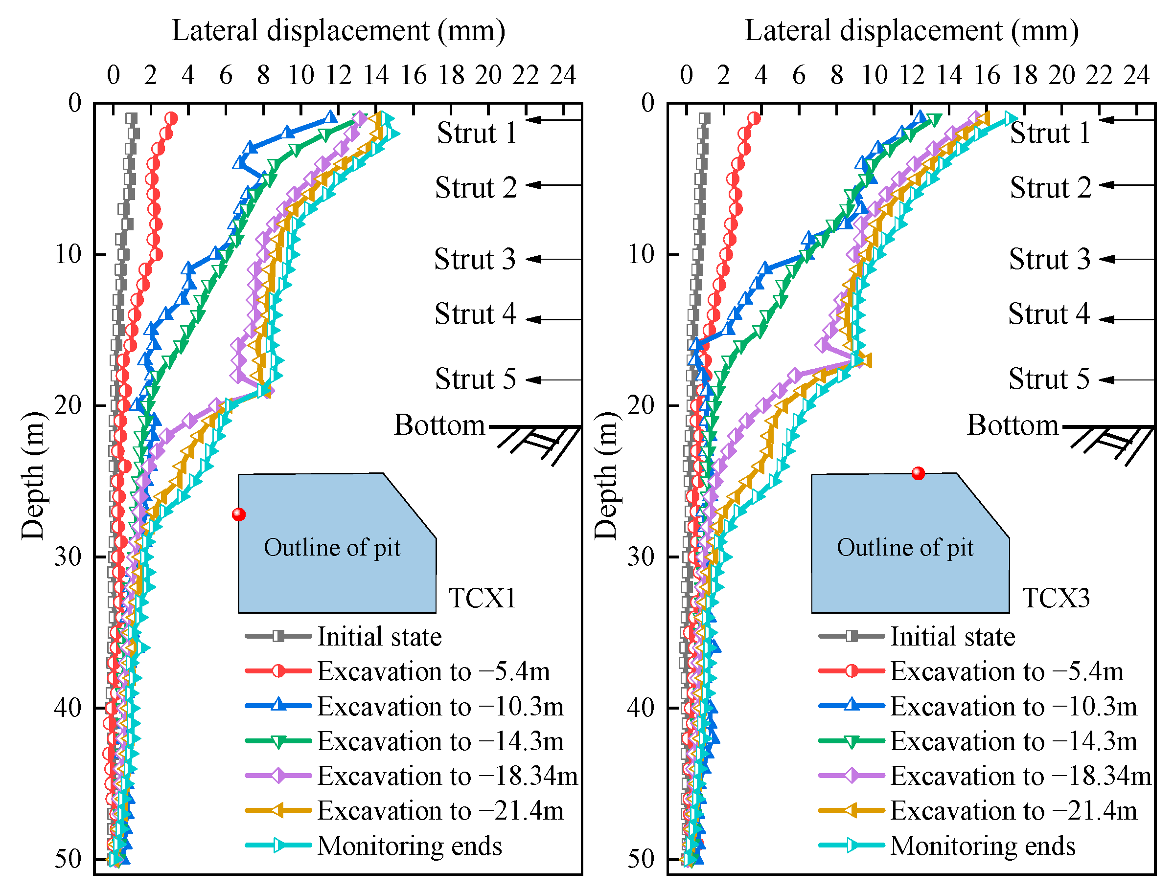
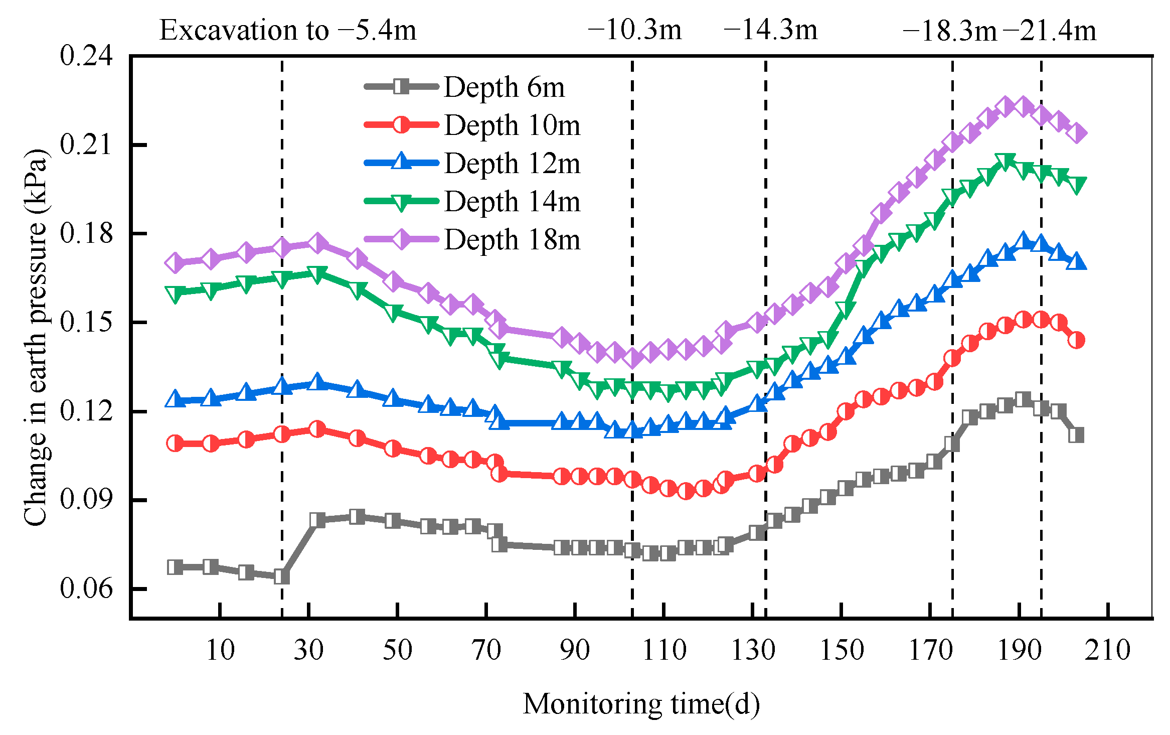
Figure 9 shows the horizontal displacement curve of the soil behind the diaphragm wall as a function of depth. Compared to the horizontal displacement of the wall, the horizontal displacement of the soil behind the wall has a similar development rule. The maximum displacement increment also occurs during the gap between the demolition of the temporary structure and the construction of the slab. The maximum lateral displacement is found at the end of the diaphragm wall and is within the safe and controllable range. The only difference is that during the excavation of the fourth basement level, there is a significant jump in the depth displacement where the level is located. This could be attributed mainly to the fact that the excavation of this layer was in the rainy season, and the groundwater outside the pit was active, whereas the excavation of the fourth basement level was beyond the reinforced section of the trench wall, which induced the jump of the lateral displacement. Further, the abovementioned phenomenon can be verified by the curve of the cumulative incremental change in the earth pressure at different depths behind the wall, as shown in Figure 10. It can be seen from the figure that the earth pressure increment after the wall at different depths has a similar development rule, i.e., there is an accumulation of earth pressure increment from the initial stage of the pit excavation, as well as an increase in the earth pressure with depth. The change is most obvious during the soil excavation of the fourth basement level. This also verifies the jump rule of the depth displacement of the soil body outside the pit where the fourth basement level is located.
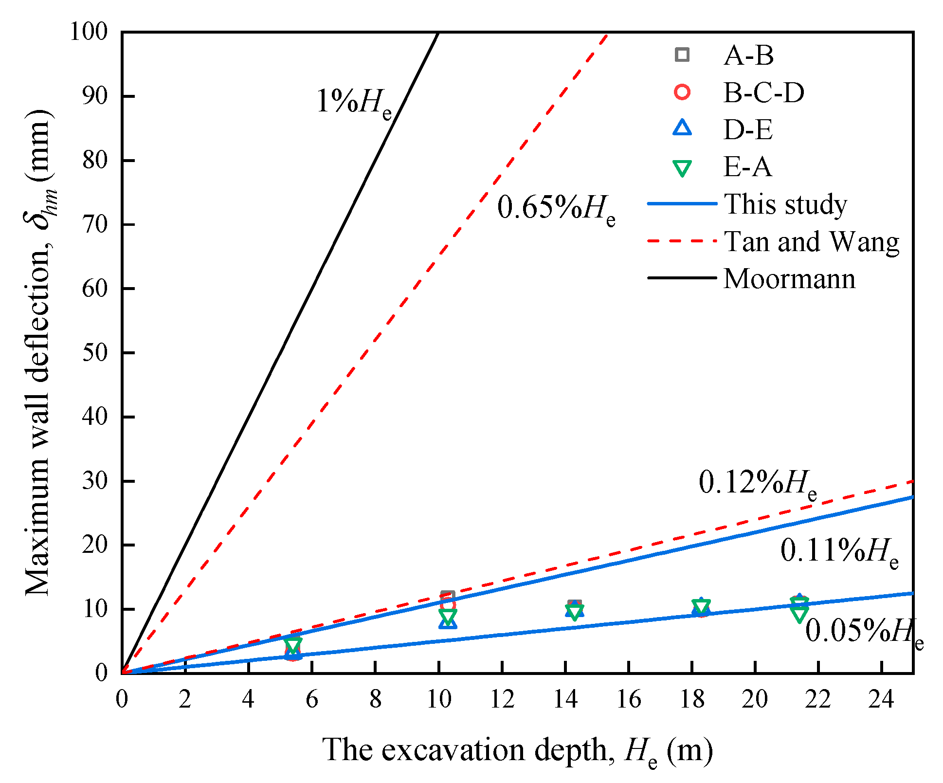
Figure 11 shows the maximum lateral displacements of the diaphragm walls as a function of the excavation depth for each excavation stage from QCX1 to QCX9. The results show that the maximum lateral displacement, δhm, is distributed between 0.05%He and 0.11%He, which is much smaller than the control requirement of δhm = 1%H proposed by Moormann [24], and even smaller compared to the lower limit of δhm = 0.12%He proposed by Tan and Wang [25]. This also indicates that although the excavation depth of this project is greater than that in the work of Moormann [24] and Tan and Wang [25], it has better control of the maximum lateral displacement. This difference is due to the fact that the 1000 mm diaphragm wall and φ1200 bored piles are used as the retaining structures with greater support stiffness, much greater than the stiffness of the retaining structure in the work by Moormann. On the other hand, the reasonable combination of the two methods of cover-cut excavation and the reverse method of open-cut excavation in the foundation pit, coupled with the two beam slabs + three structural beam supports, enables a strong integration of the support system, and efficiently controls the maximum lateral displacement of the diaphragm wall. It should be noted that the works described by Moormann and Tan and Wang have similar enclosure structure and engineering geological conditions, which are used to support the reinforcement effect of this project.

4.2.2. Diaphragm Wall Top Displacement Characteristics

The vertical displacement of the diaphragm wall is also one of the key factors for evaluating the stability of the support system. Once the vertical displacement of the diaphragm wall exceeds a certain range, it will easily lead to eccentric pressure on the support system and even induce structural instability. Hence, the settlement rules of all monitoring points at the top of the diaphragm wall at different excavation stages are plotted in Figure 12a. It can be seen from the figure that during the foundation pit construction stage, the settlement of the diaphragm wall is small, and the settlement value of each measurement point is kept within the 15 mm yellow warning range. However, while excavating the first and second basement levels, the settlement accounts for the largest amount, approximately 30–65%. This is mainly due to the fact that, after excavating the first basement level, the temporary support structure removal and the construction of the first and second slabs took a long time to complete, whereas, with the completion of the first and first-floor slabs, the integrity of the support structure was enhanced, which largely contributed to the settlement control of the diaphragm wall in the later stages. Furthermore, Figure 12b shows the settlement rule of the top of the diaphragm wall at the monitoring points D1, 3, 6, and 7 during the entire construction process. The figure also illustrates the rapid settlement during the excavation of the negative layer. Although there are fluctuations in settlement of the excavation of the remaining four layers of earth, the change is not significant, which benefits from the structural integrity of the support scheme. The settlement of the diaphragm walls essentially ceases to change until the bottom slab of the pit is concreted.
In addition, the relationship between the vertical displacement of the wall and the depth of excavation is shown in Figure 13, from which it can be seen that the maximum vertical displacement of the diaphragm wall is primarily distributed between Vwm = 0.23‰He and Vwm = 1.1‰He. The maximum vertical displacement distribution in each excavation stage is concentrated, and the maximum vertical displacement does not change much after the end of the excavation of the first basement level. This further demonstrates that the cover excavation method and the first and second slab structure can efficiently restrain the vertical displacement development of the wall.

4.2.3. Foundation Pit Adjacent Soil and Building Settlement

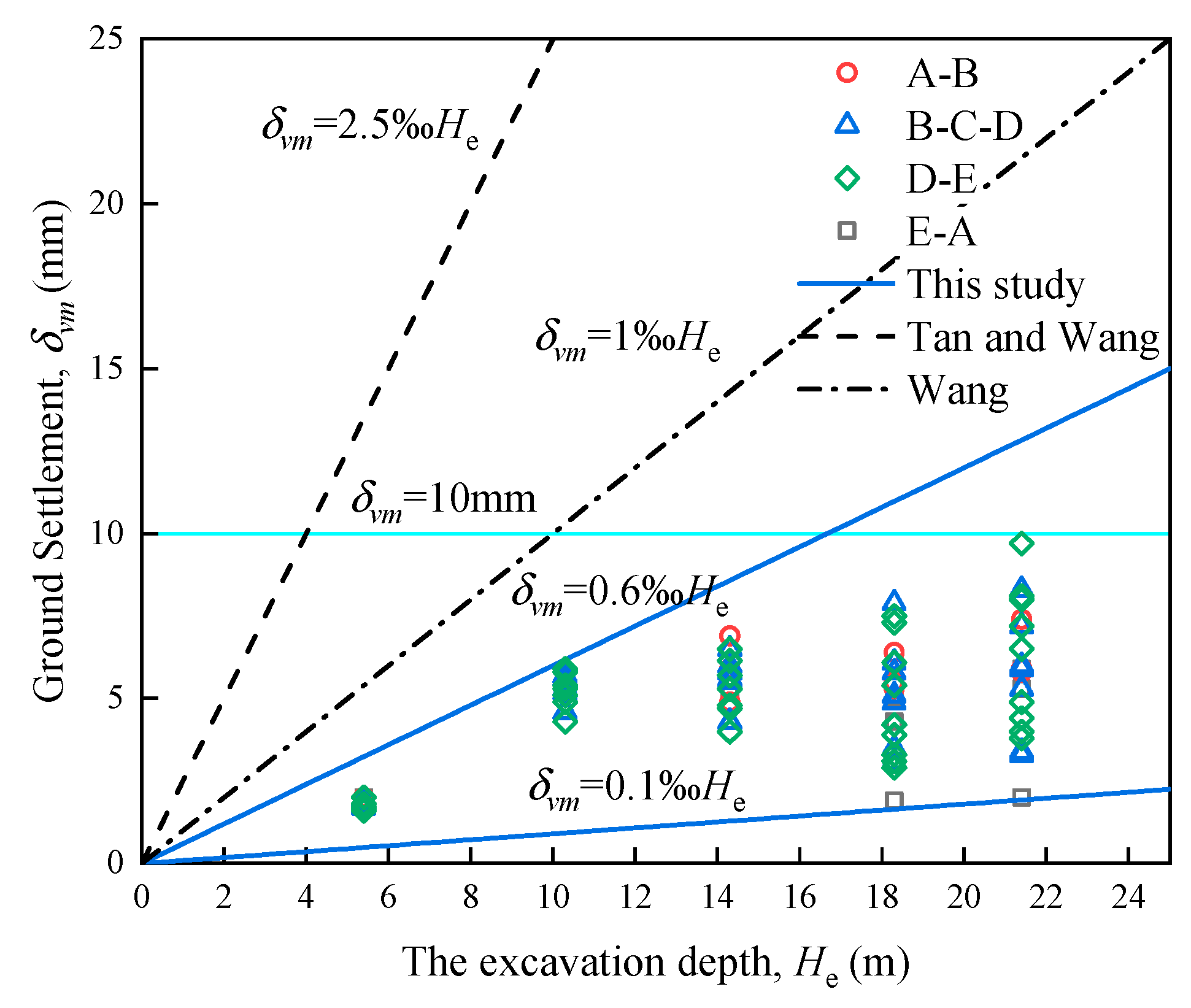
Figure 14 shows the maximum ground settlement as a function of the excavation depth for each excavation stage of the pit. Similar to the maximum vertical displacement of the wall described above, the maximum settlement at each ground settlement monitoring point is less than the 10 mm yellow warning value. This indicates that the support design method of the project can ensure the stability of the surrounding soil. The figure also shows that the maximum settlement has predominantly developed from the weak period between the removal of the temporary structure and the construction of the slab. This rule is identical to the horizontal and vertical displacement development of the diaphragm wall described above. With the increase in the excavation depth, most of the ground settlement monitoring points, δvm, are still close to δvm at the excavation depth of –10.3 m, which indicates that the impact of excavation on the surrounding environment can be efficiently controlled by using the inverse method of cover-cut excavation. In addition, Wang et al. [15] found that the variation of square foundation pit δvm in the Shanghai area with underground diaphragm wall enclosure and construction by the paralleling method was in the range of (0.10 to 0.80%)He, while this project was controlled at 0.10‰He to 0.60‰He, even lower than the lower limit of the statistics given by Wang et al. This further proves the reliability of the support design method of this project. It is also the result of the relatively conservative pit support design adopted by the designers to ensure safety and to cope with the complex surrounding environment. This also shows that there is scope for optimizing the pit design, and this can provide a reference basis for similar projects.
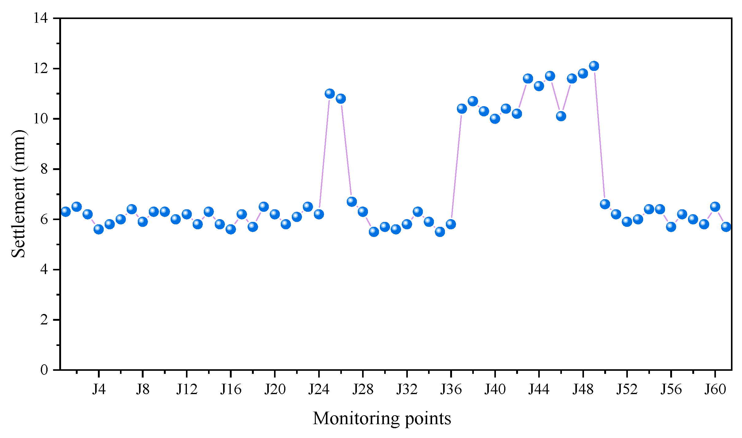
At the same time, the design method of the foundation support also has some influence on the neighboring buildings, and the maximum settlement of a total of 61 building settlement monitoring points around the foundation pit is shown in Figure 15. The figure shows that the effect of the pit construction on the neighboring buildings is also maintained at a low level, which is in the range of less than 15 mm as required by the standard. In particular, among the building settlement monitoring points, J25, J26, and J37 to J49 on the A-B side and E-A side, respectively, respond more sensitively to the foundation pit construction. This is mainly due to the constraints of the neighboring buildings in the northwest corner, which resulted in insufficient space for the construction of double-row piles. Therefore, reinforced concrete corner bracing was used instead of double-row piles. A gap period existed for the temporary structure demolition and floor slab construction after the end of the excavation of the first basement level, which caused the settlement of the building on this side to be greater than the rest.

4.2.4. Groundwater Level outside the Pit

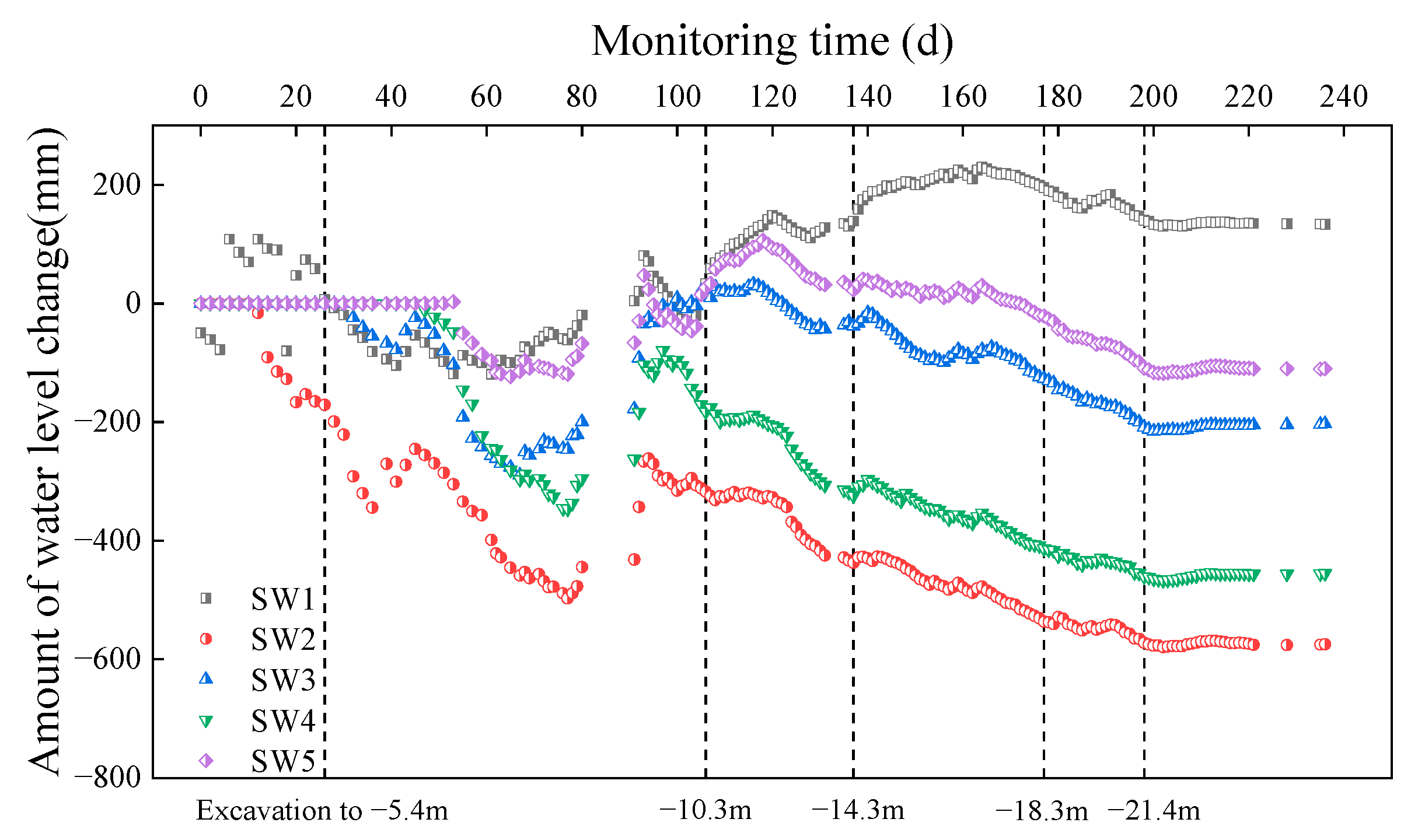
Figure 16 shows the change in the groundwater level outside the pit during excavation. As can be seen from the figure, the groundwater level at each monitoring point outside the pit has a similar development trend. During the excavation of the pit, the groundwater level outside the pit slightly fluctuates, but the change is less than the 600 mm warning range, and the water level does not change much, which does not have an obvious influence on the surrounding environment. Furthermore, it is clear that the water level changes gradually and at a low rate, which means that the abovementioned pit drainage control is quite effective, and the water level outside the pit is controlled to avoid additional deformation of the soil outside the pit caused by changes in the water level.

5. Discussion

The construction of the deep, large storage pond had high requirements for deformation and waterproof control, and its water storage capability was extremely sensitive to the changes in the wall cracks, the structural connections, etc. Hence, this project provided a safe and reliable design for the pit support, which has successfully overcome the test of typhoons and flooding, and, to date, the main underground structure has not experienced any leakage problems. The measures adopted and their effectiveness can be summarized as follows.

5.1. Deformation Control Problems and Effectiveness

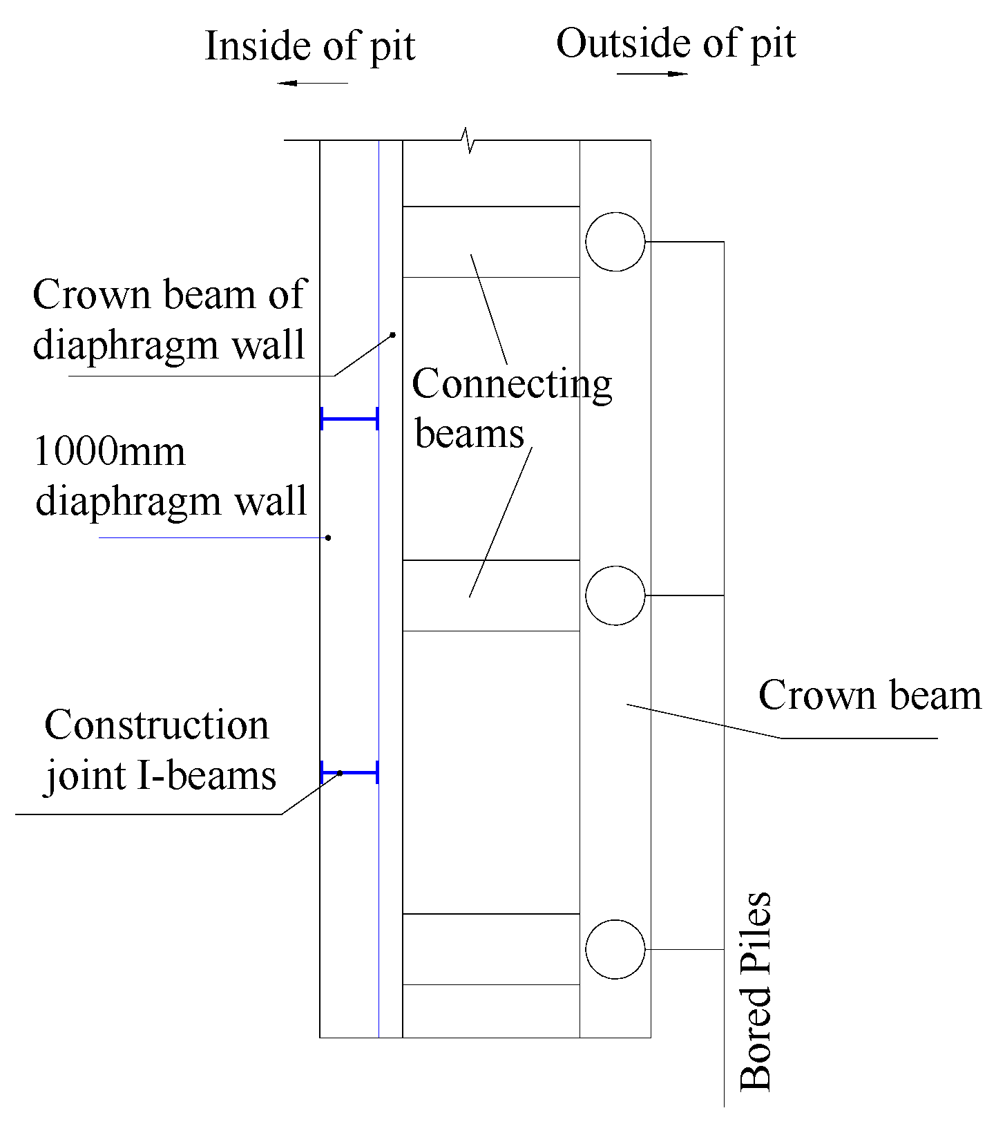
As the project is located near deformation-sensitive buildings and the underground structure would be mostly used as a storage pond after completion, it had high waterproofing and deformation requirements. Therefore, in the design of the pit support, the first basement level adopted the open excavation method, and the deformation was controlled by the diaphragm wall combined with the back row of bored piles (supplemented by the corner bracing). On the other hand, the second basement level and below adopted the cover-cut excavation method, and the deformation was controlled by two floor slabs + three structural beams (with a ring of tie beam slabs near the vertical diaphragm beam). Accordingly, the field measurement results also showed the advantages of combining the open-cut excavation method and the cover-cut excavation method. The maximum lateral displacement in the open excavation stage was less than 10 mm, whereas the growth of the lateral displacement in the cover excavation stage was controlled within 5 mm, which is sufficient to prove the reasonableness of the support design. In particular, the perimeter of the foundation pit was 412 m long, due to which it was difficult to complete the construction of the diaphragm wall at the same time. Therefore, in practice, the construction method was mostly used in sections. In order to ensure the safety and durability of the diaphragm wall, I-beam reinforcement was used at the joints of the diaphragm wall section construction in this project (as shown in Figure 17).
In order to avoid additional deformation of the pit or the surrounding buildings due to changes in the water level, the diaphragm wall was also used as a water curtain to isolate the pressurized aquifer. When arranging the drainage and pressure reduction wells, additional recharge wells were installed to avoid excessive changes in the water level outside the pit. The curve of the measured change in the groundwater level (Figure 16) also does not change sharply, i.e., the gradual change indicates that the additional deformation caused by the change in the water level was controlled. Further, the soil-hydraulic piles used as reinforcement for the trench walls further enhanced the deformation resistance of the support structure. More importantly, the deformation characteristics could be monitored using the monitoring system, and a “three-stage warning” was set up to provide real-time feedback on the deformation characteristics of the support structure. The measured results also showed that the support design implemented in this project could strictly control the deformation and ensure the safety and stability of the construction.

5.2. Tight Schedule Problems and Effectiveness

The excavation of the first basement level was completed in less than one month using diaphragm walls combined with back-row bored piles. The excavation of the second basement level and below was carried out using the cover-cut excavation method. On the one hand, this method reduced the work process, shortened the construction period, and created parallel construction conditions with the aboveground structure. On the other hand, the top slab completed in advance was used as a material stacking area, steel fabrication yard, etc., which solved the problem of restricted space and also tackled the issues of dust and noise pollution caused by the excavation process. Further, because of the large scale of the site, the construction area was divided into several blocks, and different envelopes were constructed simultaneously, which resulted in a shorter construction period. Particularly, the project also increased the excavation space and the efficiency of excavation below the first floor by reasonably designing the upper two floor slabs and the stiffness of the continuous beams to allow for a larger column distance for the lower part. The entire basement was constructed and accepted in just 14 months while simultaneously satisfying the safety requirements.

5.3. Construction Site Space Shortage Problem Treatment and Effectiveness

The pit was surrounded by sensitive buildings with limited working space. Therefore, the top and bottom slabs of the negative floor were constructed ahead of schedule (5 egresses were reserved), and the area outside the egresses was used as a construction vehicle area and a temporary loading area for work, which solved the problem of insufficient space for the construction site. Based on this, an area of approximately 16,000 m3 was released for its use as a construction site. In addition, two slabs separated the underground excavation from the main structure, which provided a separate construction environment for the above- and belowground construction and created a parallel construction condition.

5.4. Treatment and Effectiveness of the Column Problems

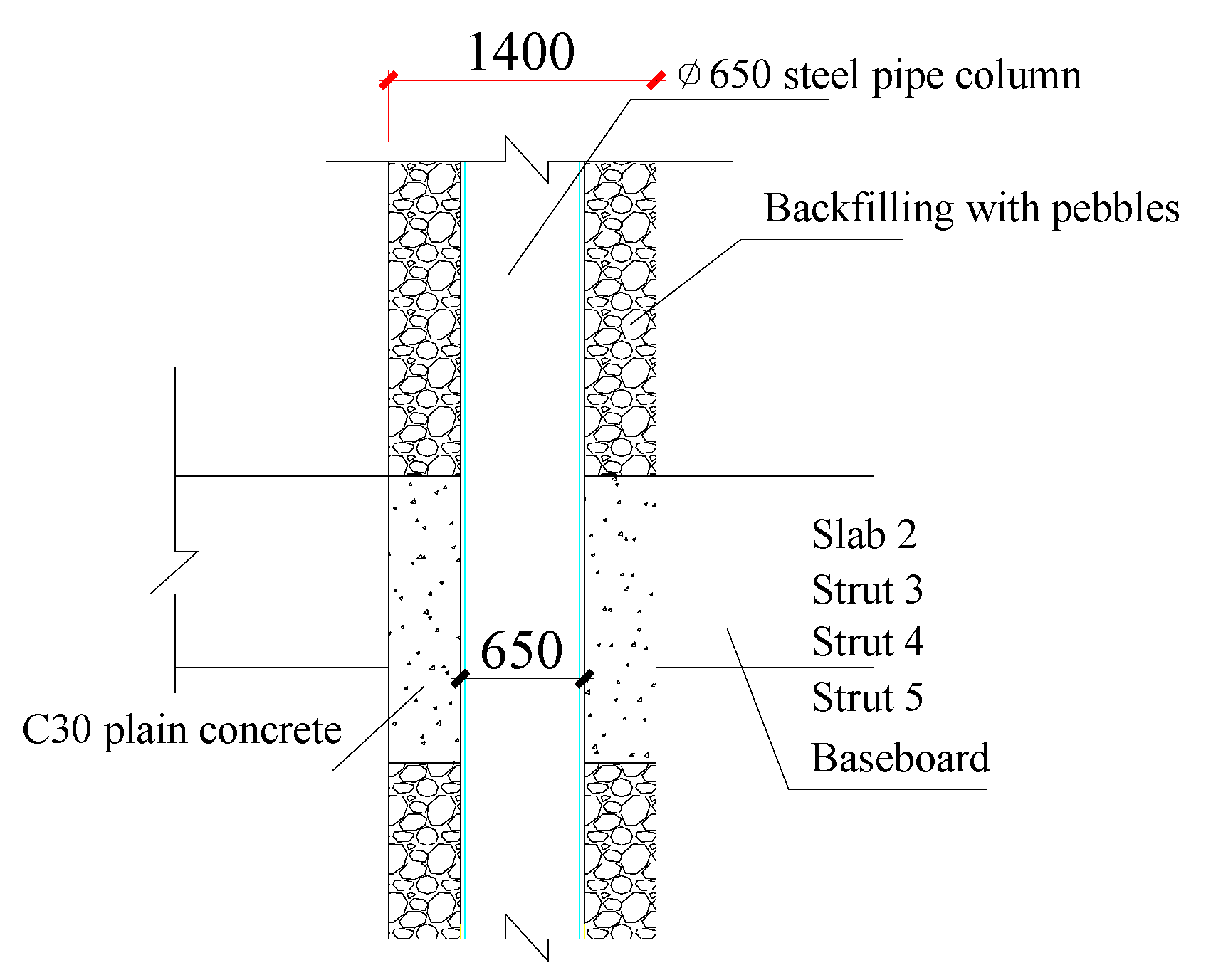
The combination of the open-cut excavation and cover-cut excavation methods inevitably has contradictory problems in the support structure, such as the stability control of the vertical column (steel pipe concrete column) in the cantilever state of the open-cut excavation by the working stage, the verticality of the steel column control problems, etc. Therefore, during the implementation of the project, in order to ensure the vertical stability of the steel columns, special devices were installed to correct the verticality of the columns to ensure that the verticality error of the columns reached 1/500~1/700 during actual construction. Furthermore, the exposed columns were protected by excavation, concrete was poured inside the columns, pebbles were used to backfill outside the columns, and 1500 mm high C30 plain concrete was poured at the location of each floor slab in the basement to reinforce the steel columns, as shown in Figure 18 showing the steel pipe column protection measures.

5.5. Sudden Surge, Flooding, and Seepage Problem Treatment and Effectiveness

In the basement excavation area, there is a pressurized aquifer ④1 (containing mud) and gravelly sand. In order to avoid the sudden surge of the pit, the pit was set up with precipitation wells to reduce the pressure. In addition, because the project is in an area that faces serious urban flooding, in order to avoid the flooding of water into the pit, the crown beam of the diaphragm wall was set up with a 2.5 m high reinforced concrete retaining wall as a buffer treatment measure for flooding. The retaining wall arrangement outside the pit is shown in Figure 6.
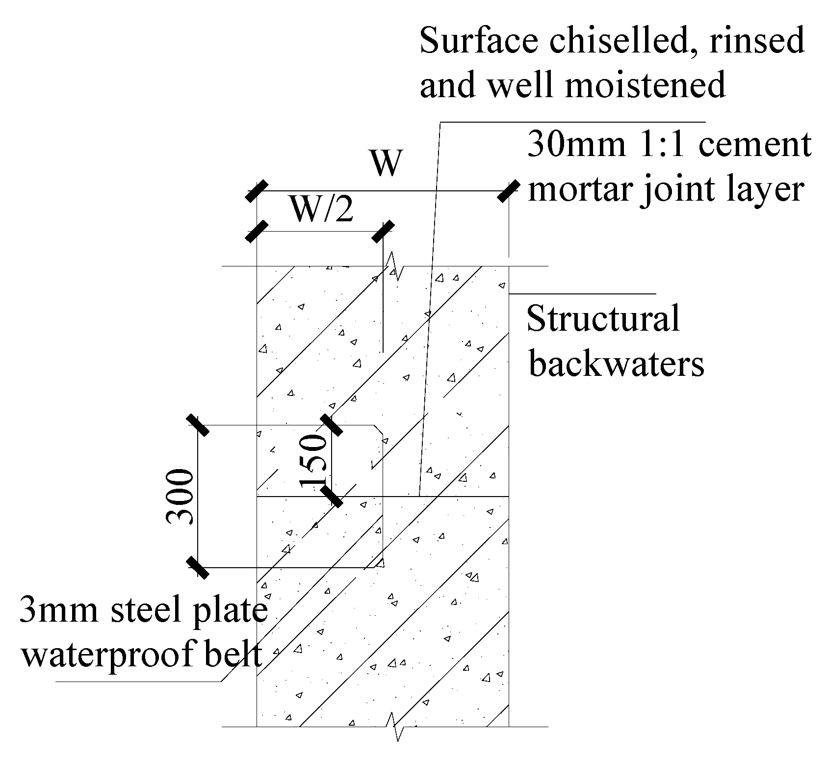
In the different stages of construction of the lining wall, the inevitable existence of construction joints is a potential element that can cause leakage in the storage pond. Therefore, in order to protect the construction joints at the location of the water-stopping effect, before the new wall work, the old wall contact surface was often chiseled, fully rinsed, and wetted by first pouring a 30 mm thick 1:1 cement mortar slurry layer. The lining wall was reserved for the insertion of reinforcement in the new wall. The construction joints were set up in the longitudinal plane with 3 mm reinforced steel water stop plates to provide the best bonding effect between the old and new interface of the liner wall, which is also the key to the working performance of the storage pond. A detailed drawing of the construction joint treatment configuration can be seen in Figure 19.
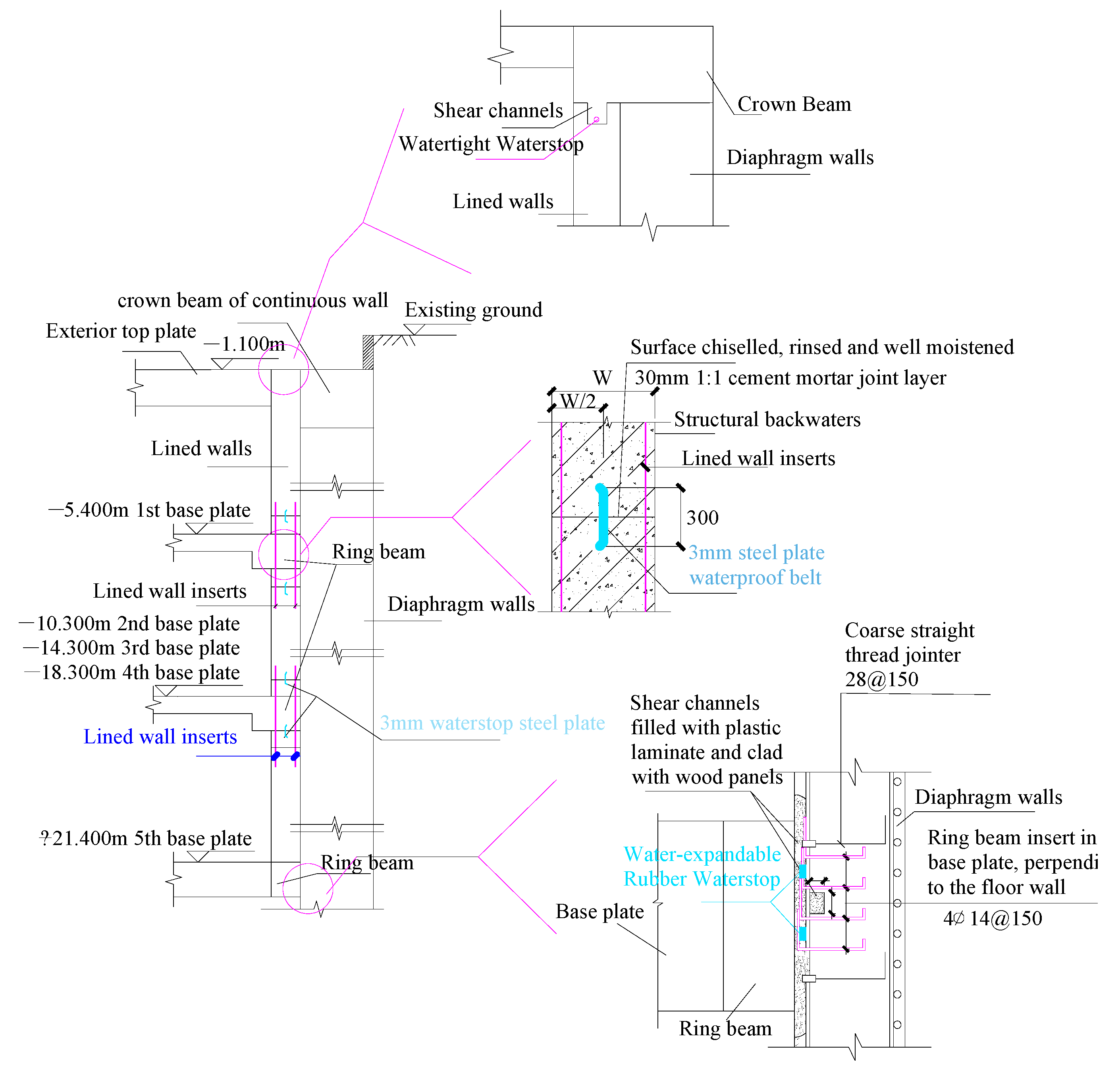
Finally, it should be noted that the basement as a storage pond, its waterproof performance, and the support system deformation control ability are equally important. Thus, to ensure the efficient waterproof performance of the basement, a series of measures were adopted, such as improving the concrete strength of the underground wall, setting a lining wall, constructing an underground diaphragm wall on both sides of the channel wall using a triaxial cement mixing pile water curtain wall for pre-reinforcement, and other measures that have achieved some effectiveness. Furthermore, for the connection of the basement elements, such as the connection of the diaphragm wall to the slab and the beam, some methods were adopted, such as the connection of the straight-threaded reinforcement joint, the connection of the pre-buried insert, etc. The leakage of the joints of the elements was prevented by installing water stops and expansion strips, as well as the slurry treatment of the bottom of the wall and pile of the diaphragm walls. Figure 20 shows a schematic of the detailed joint treatment measures for some of the support elements. As a corresponding test of the leakiness of the underground structure, the main underground structure has operated without leakage problems to date, which shows that the use of the aforementioned construction methods can be reasonably effective in ensuring the safety and stability of the underground storage pond.

6. Conclusions

This study takes a large storage pond pit project as an example, discusses the design process and overall implementation of its support structure, combines the actual on-site measurement data to analyze the development of pit deformation, and finally summarizes the key difficulties encountered while constructing the storage pond deep foundation pit project and the corresponding engineering measures. The following conclusions can be drawn:
(1)
In this project, the underground diaphragm walls and two floor slabs + three structural beams of the combined structure efficiently control the pit deformation and reduce its effect on the adjacent sensitive buildings. The pit excavation design has been applied to the key points of the pit, the difficult problems have been treated well, and waterproofing and deformation requirements of the storage pond for high-capacity water holding have been achieved.
(2)
The construction process of the pit combines the open-cut excavation method and the cover-cut excavation method, which is effective in controlling the construction period and deformation. The measurement results also show that the cover excavation method combined with the support system is superior in deformation control, whereas the open-cut excavation method is useful for shortening the construction period. However, in this method, there is uncertainty in the deformation control during the removal of the temporary structures.
(3)
The deformation characteristics of the foundation pit enclosure structure and the surrounding ground surface are within the design requirements. The horizontal displacement of the wall and the settlement of the surrounding area mainly develop from the end of the excavation of the first basement level of the temporary support structure removal and the first and the second slab construction stage. The rest of the stages benefit from the strong integrity of the support system and efficient control of deformation.
(4)
The successful implementation of a large storage pond project is inseparable from the special treatment of many key and difficult points. The treatment measures, support types, and component connection methods presented in this article can provide a reference for similar storage pond construction projects.

Author Contributions

Conceptualization, Z.L.; methodology, Z.L.; software, Z.L.; validation, Z.L.; formal analysis, Z.L.; investigation, Z.L.; resources, Z.L.; data curation, Z.L.; writing—original draft preparation, S.X. and H.D.; writing—review and editing, Z.L. and C.X.; visualization, Z.L. and C.X.; supervision, Z.L. and C.X.; project administration, Z.L. and C.X.; funding acquisition, H.D. All authors have read and agreed to the published version of the manuscript.

Funding

This research was funded by the National Natural Science Foundation of China (No. 42007235) and the Science and Technology Innovation Platform Project of Fuzhou Science and Technology Bureau (No. 2021-P-032).

Institutional Review Board Statement

Not applicable.

Informed Consent Statement

Not applicable.

Data Availability Statement

Not applicable.

Acknowledgments

The authors would like to acknowledge the financial support from the National Natural Science Foundation of China (No. 42007235) and the Science and Technology Innovation Platform Project of Fuzhou Science and Technology Bureau (No. 2021-P-032).

Conflicts of Interest

The authors declare no conflict of interest.

References

  1. Yin, J.; Ye, M.; Yin, Z.; Xu, S. A review of advances in urban flood risk analysis over China. Stoch. Environ. Res. Risk Assess. 2015, 29, 1063–1070. [Google Scholar] [CrossRef]
  2. Yin, Z.E.; Yin, J.; Xu, S.; Wen, J. Community-based scenario modelling and disaster risk assessment of urban rainstorm waterlogging. J. Geogr. Sci. 2011, 21, 274–284. [Google Scholar] [CrossRef]
  3. Zang, Y.; Meng, Y.; Guan, X.; Lv, H.; Yan, D. Study on urban flood early warning system considering flood loss. Int. J. Disaster Risk Reduct. 2022, 77, 103042. [Google Scholar] [CrossRef]
  4. Chen, S.Y. Comparison and analysis of the causes of flooding in the “7.21” rainstorm in Beijing and the “6.13” rainstorm in Shenzhen. Water Resour. Dev. Res. 2013, 13, 39–43. [Google Scholar] [CrossRef]
  5. Xu, Z.; Zhao, G.; Cheng, T. “Cities looking at the sea”: Challenges and opportunities for urban hydrology. China Flood Drought Control. 2016, 26, 54–55. [Google Scholar] [CrossRef]
  6. Xu, Z.; Ye, C. Urban storm flood simulation: Principles, models and perspectives. J. Water Resour. 2021, 52, 381–392. [Google Scholar] [CrossRef]
  7. Su, A.F.; Lv, X.N.; Cui, L.M.; Li Zhou, X.L.; Li, H. Basic observation analysis of the extreme rainstorm in Zhengzhou on 7.20. Storm Hazards 2021, 40, 445–454. [Google Scholar] [CrossRef]
  8. Wang, X.J. Application of initial rainwater storage tank in urban drainage system. China Water Supply Drain. 2012, 28, 45–47. [Google Scholar] [CrossRef]
  9. Wang, W.; Ding, W.; Yang, X.; Zheng, G.; Xu, Z. Foundation Pit Engineering and Underground Engineering—New Technologies for Energy Efficient, Low Environmental Impact and Sustainable Development. J. Civ. Eng. 2020, 53, 78–98. [Google Scholar] [CrossRef]
  10. Yu, K.; Li, D.; Yuan, H.; Fu, W.; Qiao, Q.; Wang, S. Theory and practice of “sponge city”. Urban Plan. 2015, 39, 26–36. [Google Scholar] [CrossRef]
  11. Rijke, J.; Farrelly, M.; Brown, R.; Zevenbergen, C. Configuring transformative governance to enhance resilient urban water systems. Environ. Sci. Policy 2013, 25, 62–72. [Google Scholar] [CrossRef]
  12. Li, M.; Zhang, Z.; Chen, J.; Wang, J.; Xu, A. Zoned and staged construction of an underground complex in Shanghai soft clay. Tunn. Undergr. Space Technol. 2017, 67, 187–200. [Google Scholar] [CrossRef]
  13. Moormann, C. Analysis of Wall and Ground Movements Due to Deep Excavations in Soft Soil Based on a New Worldwide Database. J. Jpn. Geotech. Soc. 2008, 44, 87–98. [Google Scholar] [CrossRef] [Green Version]
  14. Shi, J.; Liu, G.; Huang, P.; Ng, C.W.W. Interaction between a large-scale triangular excavation and adjacent structures in Shanghai soft clay. Tunn. Undergr. Space Technol. 2015, 50, 282–295. [Google Scholar] [CrossRef]
  15. Wang, J.H.; Xu, Z.H.; Wang, W.D. Wall and Ground Movements due to Deep Excavations in Shanghai Soft Soils. J. Geotech. Geoenviron. Eng. 2010, 136, 985–994. [Google Scholar] [CrossRef]
  16. Zhang, W.G.; Goh, A.T.C.; Goh, K.H.; Chew, O.Y.S.; Zhou, D.; Zhang, R. Performance of braced excavation in residual soil with groundwater drawdown. Undergr. Space 2018, 3, 150–165. [Google Scholar] [CrossRef]
  17. Cheng, K.; Xu, R.; Ying, H.; Gan, X.; Zhang, L.; Liu, S. Observed performance of a 30.2 m deep-large basement excavation in Hangzhou soft clay. Tunn. Undergr. Space Technol. 2021, 111, 103–872. [Google Scholar] [CrossRef]
  18. Wang, W.; Weng, Q.; Wu, J. Design and analysis of ultra-deep pull-out resistant piles for 500kV underground substation at Shanghai World Expo. Build. Struct. 2007, 05, 107–110. [Google Scholar] [CrossRef]
  19. Pakbaz, M.S.; Imanzadeh, S.; Bagherinia, K.H. Characteristics of diaphragm wall lateral deformations and ground surface settlements: Case study in Iran-Ahwaz metro. Tunn. Undergr. Space Technol. 2013, 35, 109–121. [Google Scholar] [CrossRef]
  20. Wang, Y.; Zhang, F. Effects of Pit-Bottom-Soil Reinforcement on the Deformation of Subway Deep Foundation Pits Based on an Improved Model. Adv. Mater. Sci. Eng. 2022, 2022, 2661311. [Google Scholar] [CrossRef]
  21. Fang, J.H.; Zhang, C.H.; Zhang, J.Y. Application of Artificial Freezing Method in the Rehabilitation of Line 4 of Shanghai Rail Transit. J. Civ. Eng. 2009, 42, 124–128. [Google Scholar] [CrossRef]
  22. Tan, Y.; Lu, Y. Forensic Diagnosis of a Leaking Accident during Excavation. J. Perform. Constr. Facil. 2017, 315, 4017061. [Google Scholar] [CrossRef]
  23. Feng, R.; Zhang, Q.; Liu, S. Experimental Study of the Effect of Excavation on Existing Loaded Piles. J. Geotech. Geoenviron. Eng. 2020, 146, 4020091. [Google Scholar] [CrossRef]
  24. Liang, R.; Wu, J.; Sun, L.; Shen, W.; Wu, W. Performances of adjacent metro structures due to zoned excavation of a large-scale basement in soft ground. Tunn. Undergr. Space Technol. 2021, 117, 104–123. [Google Scholar] [CrossRef]
  25. Yong, T.; Wang, D. Characteristics of a Large-Scale Deep Foundation Pit Excavated by the Central-Island Technique in Shanghai Soft Clay. Ⅱ: Top-Down Construction of the Peripheral Rectangular Pit. J. Geotech. Geoenviron. Eng. 2013, 139, 1894–1910. [Google Scholar] [CrossRef]
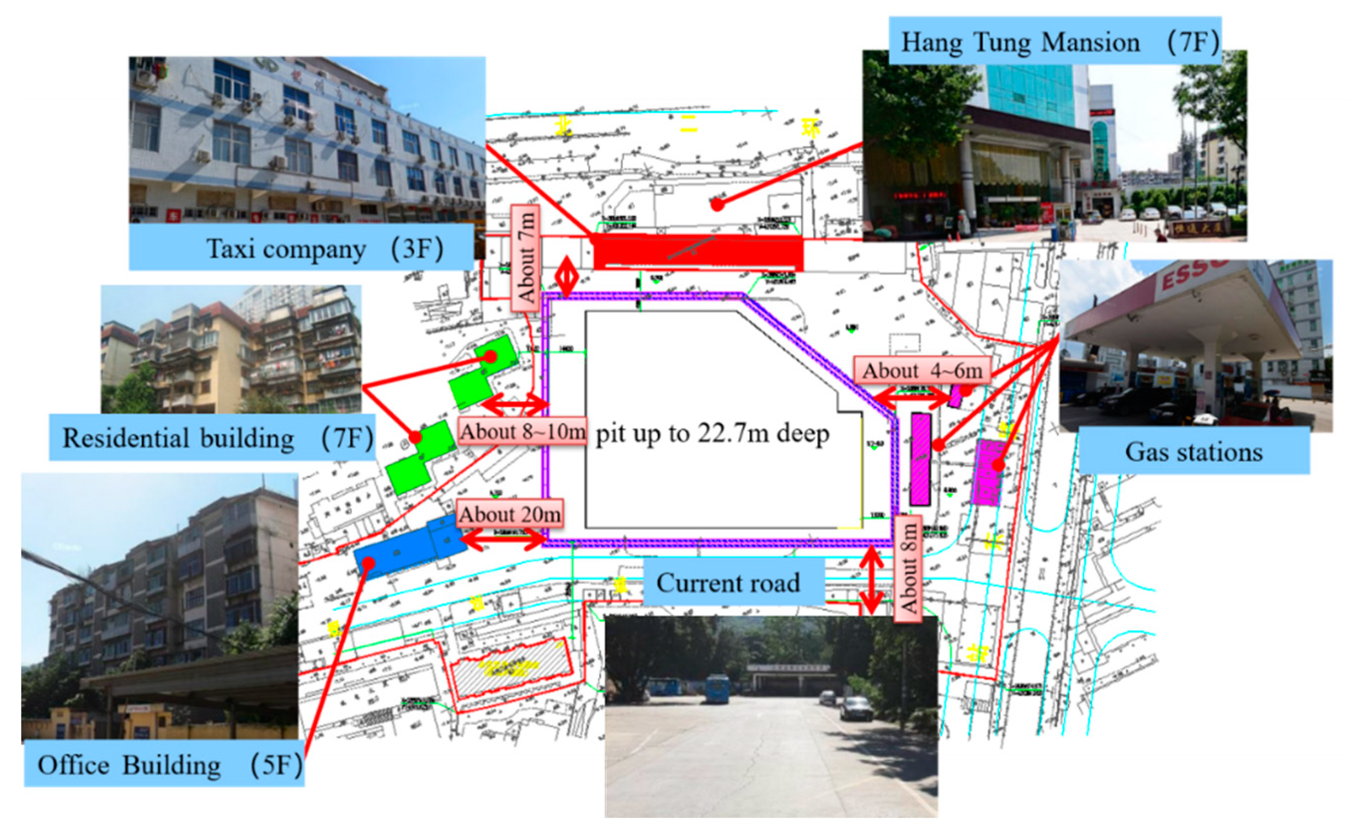
Figure 1. Surrounding complex environment.
Sustainability 14 14046 g001
Figure 2. Schematic layout of double-row piles and local corner bracing.
Sustainability 14 14046 g002
Figure 3. A 1-1’ Schematic diagram of typical sectional enclosure structure.
Sustainability 14 14046 g003
Figure 4. Double-row pile stability calculation.
Sustainability 14 14046 g004
Figure 5. Trench wall reinforcement: (a) vertical section, (b) pile top plane.
Sustainability 14 14046 g005
Figure 6. Top of retaining wall profile.
Sustainability 14 14046 g006
Figure 7. Monitoring plan layout.
Sustainability 14 14046 g007
Figure 8. Horizontal displacement curve of the wall.
Sustainability 14 14046 g008
Figure 9. Horizontal displacement curve of the soil behind the wall.
Sustainability 14 14046 g009
Figure 10. Ty2 soil pressure increment at different depths behind the wall.
Sustainability 14 14046 g010
Figure 11. Maximum lateral displacement of diaphragm wall versus excavation depth.
Sustainability 14 14046 g011
Figure 12. Settlement at top of continuous wall: (a) different monitoring points, (b) over time.
Sustainability 14 14046 g012
Figure 13. Maximum vertical displacement of continuous wall versus depth.
Sustainability 14 14046 g013
Figure 14. Settlement curve of adjacent soil.
Sustainability 14 14046 g014
Figure 15. Cumulative Maximum Settlement of Adjacent Buildings.
Sustainability 14 14046 g015
Figure 16. Groundwater level change over time.
Sustainability 14 14046 g016
Figure 17. Wall top plane.
Sustainability 14 14046 g017
Figure 18. Diagram of protection measures for steel pipe columns.
Sustainability 14 14046 g018
Figure 19. Construction joint treatment of lining wall.
Sustainability 14 14046 g019
Figure 20. Support structure connection treatment diagram.
Sustainability 14 14046 g020
Table 1. Typical soil properties of the construction site.
Geotechnical NameThicknessNatural Density γWater Content wModulus of Compression
Es0.1–0.2
Cohesion cFriction Angle φ
m(kN/m3)%(MPa)(kPa)(°)
① Mixed fill0.90~2.8017.0--10 *15 *
② Powdery clay0.50~2.2018.5732.74.8621.110.7
③ Silt8.90~13.4015.5466.61.785.71.5
④ Powdery clay8.90~13.4019.0626.65.8625.913.6
1 Gravelly coarse sand (with mud)0.70~5.6019.0-155 *28 *
⑤ Residual clayey soil1.70~7.9018.3953.94.3223.417.7
⑥ Fully weathered granite2.80~11.5019.030.3402025
⑦ Sandy, strongly weathered granite8.70~25.5021.0-603030
Note: Values with * indicate regional empirical reference values.
Table 2. Construction sequence.
Construction StepsConstruction Content
1Construction preparation
2Construction of enclosure structure, steel pipe column, and column pile
3Excavation and construction of crown beam and connecting beam
4Excavation to −5.4 m (first basement level, open excavation)
5Construction of bedding layer and the second slabs (leaving 5 openings for later cover excavation)
6Construction of concrete corner braces and columns (temporary support structure above the negative level)
7Construction of the wall column of first basement level, construction of the first slab of first basement level (leaving 5 openings for cover excavation)
8Excavation to −10.30 m (second basement level, this process and subsequent processes are cover excavation)
9Matting, third support construction, and second basement level side wall construction
10Excavation to −14.30 m (third basement level)
11Matting, fourth support construction, and third basement level side wall construction
12Excavation to −18.30 m (fourth basement level)
13Matting, fifth support construction, and fourth basement level side wall construction
14Excavation to −21.40 m (fifth basement level)
15Construction of mat, basement floor, and side wall of fifth basement level
Table 3. Three-stage alarm values.
Monitoring ProjectsRed Warning ValueOrange Warning ValueYellow Warning Value
Accumulation
(mm)
Rate of Change
(mm/d)
Accumulation
(mm)
Rate of Change
(mm/d)
Accumulation
(mm)
Rate of Change
(mm/d)
Horizontal displacement at the top of the diaphragm wall>30>3>20>2.5>15>2.0
Vertical displacement at the top of the diaphragm wall>30>3>20>2.5>15>2.0
Deep horizontal displacement>30>3>20>2.5>15>2.0
Building deformation>15>3>10>1.5>5>1
Groundwater level>1000>500>800>400>600>300
Surrounding surface subsidence>30>3>20>2.5>15>2.0
Publisher’s Note: MDPI stays neutral with regard to jurisdictional claims in published maps and institutional affiliations.