Article

Multi–Disciplinary Optimizations of Small-Scale Gravitational Vortex Hydropower (SGVHP) System through Computational Hydrodynamic and Hydro–Structural Analyses

by
Yingzi Jiang
1,
Arul Prakash Raji
2,
Vijayanandh Raja
2,*,
Fuzhang Wang
1,3,
Hussein A. Z. AL-bonsrulah
4,*,
Ramesh Murugesan
5 and
Sudhakaran Ranganathan
6
1
School of Mathematics and Statistics, Xuzhou University of Technology, Xuzhou 221018, China
2
Department of Aeronautical Engineering, Kumaraguru College of Technology, Coimbatore 641049, Tamil Nadu, India
3
Nanchang Institute of Technology, Nanchang 330044, China
4
Department of Mechanical Engineering, Faculty of Engineering, Kufa University, Najaf 54002, Iraq
5
MaDeIT Innovation Foundation, IIITDM Kancheepuram Campus, Chennai 600127, Tamil Nadu, India
6
Department of Mechanical Engineering, SNS College of Engineering, Coimbatore 641107, Tamil Nadu, India
*
Authors to whom correspondence should be addressed.
Sustainability 2022, 14(2), 727; https://doi.org/10.3390/su14020727
Submission received: 12 December 2021 / Revised: 31 December 2021 / Accepted: 7 January 2022 / Published: 10 January 2022
(This article belongs to the Special Issue Energy in the 21st Century Prospects and Sustainability)

Abstract

:
Hydropower is a superior energy extraction approach, which has been made to work based on renewable energy sources. In the generation of hydropower, Gravitational Vortex Hydropower (GVHP) plays a predominant contributor role because of its free turbulence-relayed energy utilization concept and flexible as well as compact size. Owing to the huge contribution of GVHP in the hydropower sector, multi-objective-based investigations have emerged. However, there is still insufficient literature available for the technology to precede optimum turbine blade design. Two important categories are involved in these multidisciplinary investigations, in which the first phase, a numerical investigation has been done using ANSYS to identify the location of maximum tangential velocity in a conical basin with different notch angles, conical angles, basin shapes, anddiameters. In this second phase, the focal aim is to carry out the numerical investigation on Gravitation Vortex Turbine Blades (GVTB) for the different geometry in order to get the optimum power output with a high structural lifetime through HSI (Hydro–Structural Interaction) computation. The entire conceptual designs of this SGVHP and its hydro-rotors are modeled with the help of CATIA. ANSYS Fluent is a CFD (Computational Fluid Dynamics) numerical tool, which is primarily used in this paper for all the hydrodynamic analyses. Finally, the standard analytical approaches are used for the comparative determinations of thrust production by hydro-rotors, power extraction by hydro-rotors, and propulsive efficiency for the selection process of best hydro-rotors. HSI analyses are additionally carried out and thereby the suitable lightweight material is picked.

1. Introduction

Electrical energy is always playing a predominant role in the day-to-day activities of people so it must be investigated thoroughly in order to hold its availability at a good level. Instead of the execution of an investigation on reducing the usage of electrical energy, the investigation on the innovation of electrical energy production through renewable source platforms should be executed. Comparatively, electrical energy creation through hydro fluids is very complicated and superior when compared with other sources such as solar systems, windmill systems, etc. This is because the hydro fluid is much denser than other electrical energy production-based fluids so the impact on energy converters such as turbines, sheets, etc., is greater. Through this great impact on rotors, integrative outcomes have happened in hydropower sectors. The integrative effects are comprised of both negative and positive conclusions, wherein the positive conclusion is that the impact force on the rotor is high so the possible energy extraction is quite lofty and the negative conclusion is that the possibility of structural failure is higher due to its greater fluid density. Therefore it is confirmed that electrical energy extraction in a hydrodynamic environment is the best platform to extract a huge amount of energy, which has been increased the research on hydropower and its utilization components. In particular, two different perspectives have been analyzed in a deep manner in hydropower, which are investigations on the basic design factors of hydropower systems and multidisciplinary investigations on the hydropower extraction unit, i.e., hydro-rotor. With the forceful consideration of the above-mentioned perspectives, the flexible and compact hydropower system picked for this current research is Gravitational Vortex Hydropower (GVHP). This concept of the GVHP turbine has been introduced recently under the category of hydropower technologies and has a lot of scope for research in many aspects [1]. The proposed and imposed GVHP is pictorially revealed with its design factors in Figure 1.
The important basic design parameters of GVHP such as basin diameter, conical angle, and notch angle are shown clearly in Figure 1. The conventional outer boundaries of the GVHP are circular shapes on its top surface and thereby linear association of convergent duct till its bottom region. GVHP is flexible in design scale, which means as per the power requirement and user’s implementation criteria the entire Gravitational Vortex Hydropower System (GVHPS) can be enlarged or dwindled without creating any complicated troubles. Mostly compact size GVHPs have been implemented in real-time applications therefore this work finalized to do multidisciplinary investigations on entire compact size GVHPS. Apart from all other pros of the GVHP, it predominantly depends upon the turbulence behavior of hydro fluid for its high energy extraction. Due to this turbulence dependency, naturally, the hydrodynamic effect and its flow behavior play a very important role in GVHP in the perspective of high energy production. This aforesaid dependency, furthermore, ensures the research on GVHP is focused on extracting high electrical energy from hydrodynamic medium [1].

Literature Survey

Ajay Kumar Jha et al. performed a numerical investigation on the effect of foremost parameters for the conical basin in a gravitational water vortex turbine.From the results, they concluded that basin inlet was the most important factor to be considered while designing a gravitational water vortex turbine. Additionally, notch length should not be decreased beyond the critical value, because it creates undesirable turbulence at the inlet region [1]. Alejandro Ruiz Sánchez et al. 2019 did a performance study on compact size GVHP through computational and experimental approaches. The turbulent flow-based incompressible analyses were computed in an advanced numerical tool (ANSYS Fluent). In which a bi-phase kind of simulation was used with the fluid properties of air and water with the reference temperature of 298.15 K and reference pressure of 101,325 Pa. The turbulence model picked for this computation is BSL RSM and the inlet fluid velocity was 0.15 m/s. The grid convergence test was organized with the number of mesh cases as six. Additionally, the experimental study was completed in ITM, in which two different GVHPs were tested. The imposed models were a concave shape-based basin and a convex shape-based basin GVHP. Both the models were tested and thereby the outcomes were noted, which are RPM (Rotational Speed per Minute), current, voltage, and electrical power. The electrical power was estimated as 0.37 watts through a concave shape-based basin GVHP and 0.23 watts through a convex shape-based basin GVHP. Both of these experimental tests are computationally validated in this current article and thereby the power estimations are calculated. After the comparison, the error percentages are obtained between 0.47% and 4.99%, so it is strongly confirmed that our current computational procedures are validated, which are able to provide highly reliable and acceptable outcomes [2]. Dipesh Thapa et al. performed a numerical investigation and thus found that the vortex flow channel with rectangular and circular inlets tends to produce more symmetric pressure variation in comparison to triangular and curved geometry [3]. Christine Power et al. 2015 performed an investigation which concluded that the efficiency of the turbine increases with an increase in blade size and the number of blades for different blade configurations tested. Maximum power from the turbine was found for the maximum flow rate tested and when there was a substantial resistance force applied to the turbine [4]. Sreerag S. R et al. did a performance investigation on GVHP and thus found that maximum tangential velocities are obtained when outlet diameter approaches 30% of basin diameter. So, when GVHP with basin geometry of conical shape is to be built, an outlet diameter which is 0.3 times the basin diameter (0.3D) gives the maximum output [5]. Subash Dhakal et al. obtained that the best location for placing the turbine is the bottom of the basin. The value of the tangential velocity head increases with the increase in the depth of the conical basin. Hence they concluded that greater efficiency was noted at the bottom. Likewise, the values of efficiency were higher for gravitational vortex turbines with a smaller number of blades [6]. Sujate Wanchat et al. found that for a 1 m diameter cylindrical vortex basin, the suitable outlet diameter was in the range of 0.2 to 0.3 m. The operating hydro head of the free vortex was in the range of 0.3 to 0.4 m. The maximum power output obtained was 60 W at 0.2 m outlet diameter and the head of the free vortex was at 0.4 m [7].
From the literature survey, it has been observed that still there is a lot of scope to obtain the optimal operating conditions of GVHPS. In particular, the outer boundaries, the design angles, and the convergent paths of Gravitational Vortex Hydropower Turbines need to be improved from the existing components. This research work can also be considered for the wide range of areas requiring investigation including
  • To optimize the geometrical parameters of the basin, and notch and conical angles to obtain maximum tangential velocity.
  • Understanding the physical principle behind the vortex flow field and thereby impact on hydro-rotors, which are essential when considering energy extraction.
  • Optimizing the geometry and size of turbine blades to extract more power from the maximum vortex strength (rotational energy).
  • To do the numerical investigation on GVHP with different turbine blade profiles and its construction materials through HSI (Hydro–Structural Interaction) analysis in order to obtain the optimum blade design and suitable lightweight material which agrees with the maximum vortex velocity structure and also it will contribute to the maximum power output [1,2,3,4,5,6,7,8,9,10].

2. Proposed Methodology—Computational Hydrodynamic Analysis

The primary target of this work is analyses of hydrodynamic performance in the GVHP, in which various hydro-rotors are used at the optimized place. Because of this complicated target, only experimental and computational analyses are capable to provide acceptable outputs. Relatively, computational simulations are better than experimental testing in the perspective of high flexibility, low time consumption, and low cost for more than one analysis, i.e., comparative analyses. Therefore the Computational Hydrodynamic Analysis (CHA)-based studies are executed in this work for all the cases [8,9,10].

2.1. Conceptual Design

The fundamental step of the CFD simulation is the conceptual design of a real-time object, in which the unique design specifications are perfectly reflected from the real-time object into a physical computer model. In general, the pictorial representations can easily be understood, similarly, this conceptual design is also a kind of pictorial representation of real-time objects but it is advanced in the perspectives of provision of accrued three-dimensional data, and reflections of engineering design profiles in a correct manner. Engineering-based conceptual designs are mostly modeled through CADD software. In this work, CATIA (Computer Aided Three-dimensional Interactive Application) is used for the constructions of SGVHP with all hydro-rotors, in which complicated shapes such as SGVHP profiles and various rotors’ design profiles are perfectly modeled with the help of the uniqueness of the CATIA tool. In this modeling phase, a great amount of care has been given because of the rotohydrodynamic nature of this work. In particular, the hydrofoil shapes have the ability to provide useful hydrodynamic forces, which may increase the efficiency of SGVHP. As a result of this positive effect, the hydrofoils are shortlisted from the previous studies, in which the chord, the camber, and other design parameters data are evaluated correctly and implemented in the hydro-rotors perfectly. Apart from this unique characteristic, one more common performance parameter is also considered for modeling, which is nothing but the area of the hydro-rotor and its supportive parameter, i.e., diameter. This work intends to extract a high amount of power from SGVHP by means of locating the hydro-rotors in the highly fluid velocity generation place inside the SGVHP. Thus the location of fluid velocity and its cone dimensions are already evaluated from previous work, which guided the area and diameter of the hydro-rotors. Based on the previous work, the performance relayed design parameters are evaluated correctly and thus the rotors are fixed in the perfect location with the help of the assembly facility of the CATIA tool. In total, four different hydro-rotors are finalized and modeled through a modeling tool, in which the hydro fluid energy absorption by hydrodynamic behavior of hydro-rotor is the only thin involved predominantly in the selection process [11,12,13,14,15,16,17].

2.1.1. Symbols and Notations

Since this multi-perspective-based investigation is planned to compute parametric analyses on both SGVHP and its hydro-rotors, the few design parameters of the hydro-rotor areextracted from the internal construction of SGVHP. The extracted few design parameters are the optimum diameter and optimum height of the hydro-rotor. Inclusive of these known design parameters, the design, and construction of all the hydro-rotors are been derived. Table 1 contains detailed information of symbols and notations involved in the design stage of hydro-rotors.

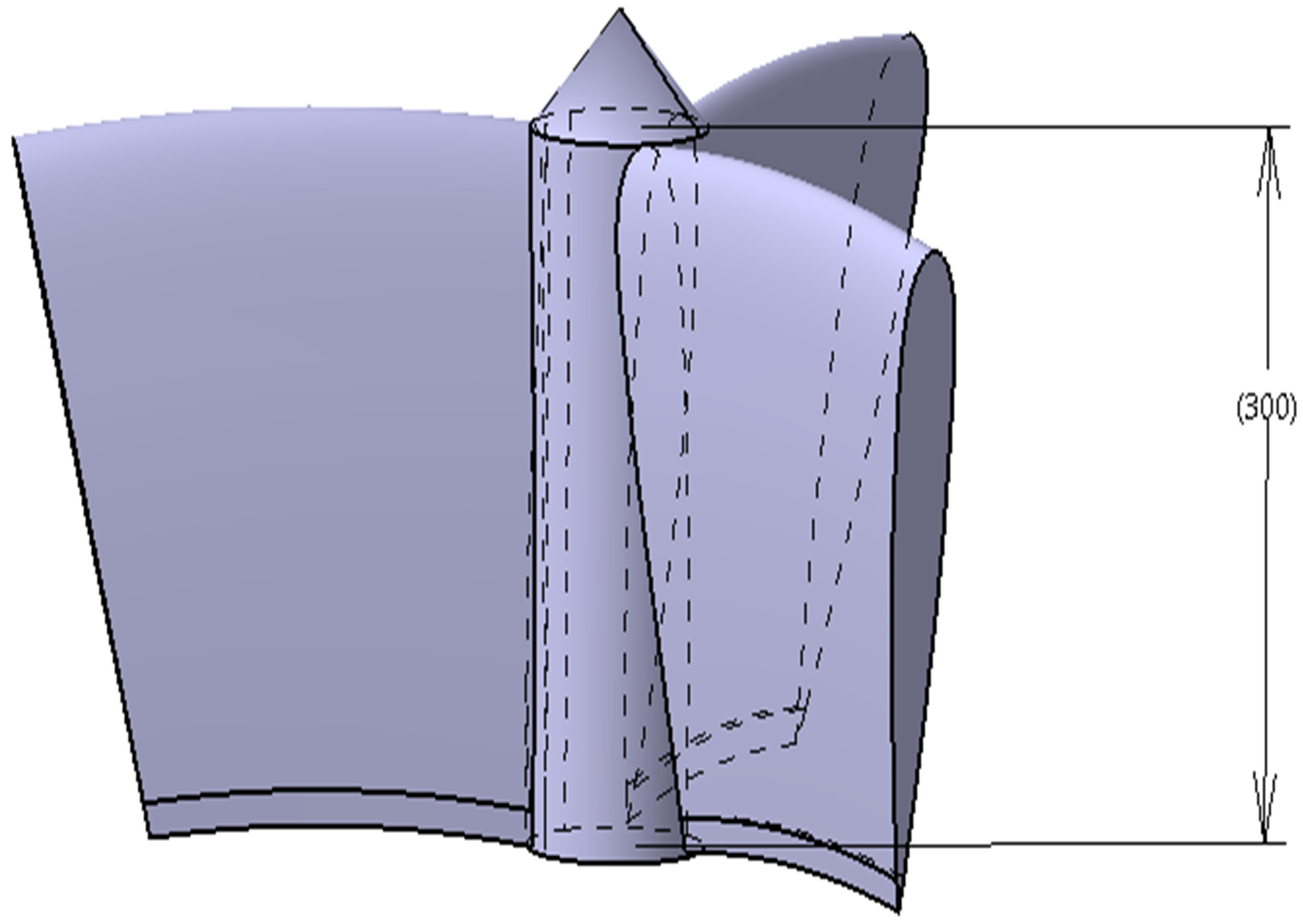
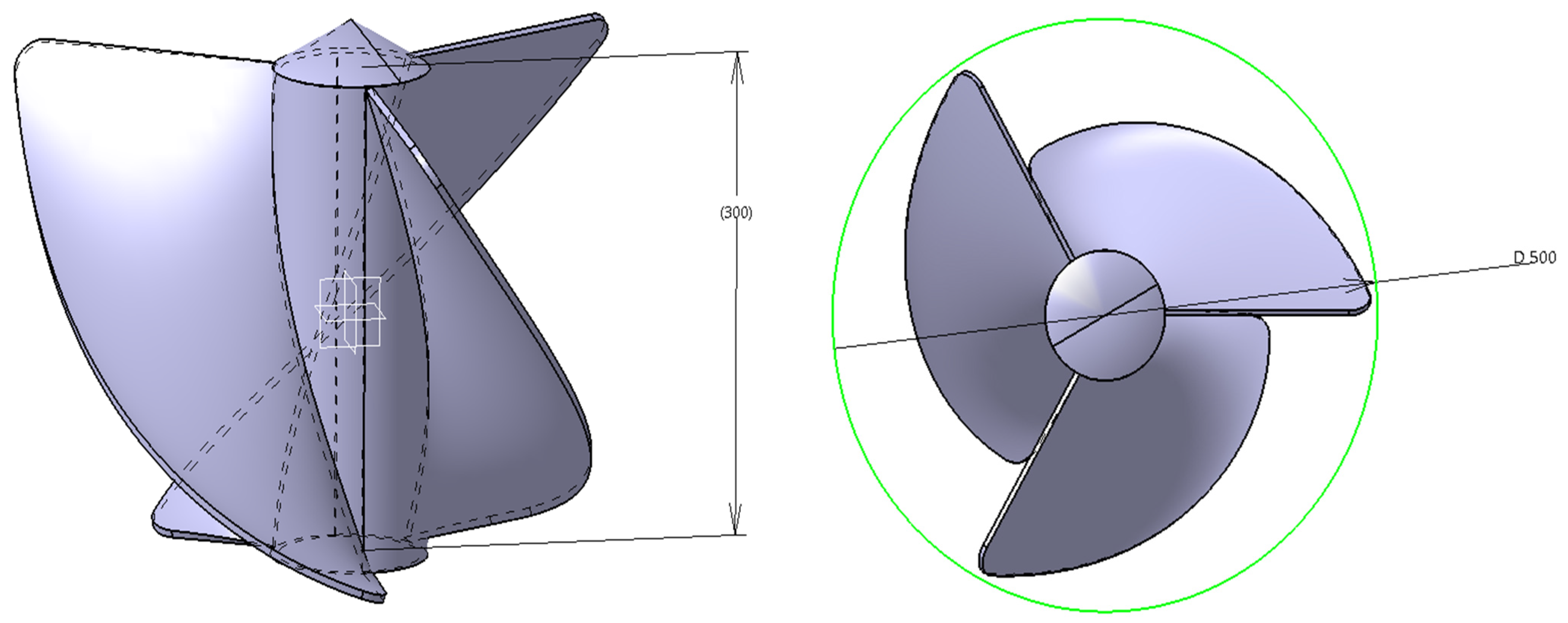
2.1.2. Hydro-Rotor–I

The first hydro-rotor of this work is developed conceptually based on the standard analytical formulae belonging to the aircraft propeller. This kind of propeller provides better thrust force when the aircraft is in motion, so firstly this unique and efficient propeller is tested as a hydro-rotor of this SGVHP. The standard analytical approach involved in this propeller construction is given in Equations (1)–(4) [18].
T = 0.5 ρ A [ ( V Induced ) 2 ( V Hydrostatic ) 2 ]
P P D = 0.6
θ =   arctangent ( P P 2 π r S )
b = 8 π ( sin ( θ ) ( tan ( θ ) 1 1.2 tan ( θ ) ) ( 1 + 1 1.2 tan ( θ ) ) ) r S n C L
Apart from the known optimum diameter and height, the number of the blades is assumed as three except the Savonius hydro-rotor. With the help of Equations (1)–(4), and assumed design data, the design parameters of Hydro-Rotor–I are constructed. Figure 2 reveals the typical views of Hydro-Rotor–I, in which the typical conceptual design and its dimensions are explained clearly.

2.1.3. Hydro-Rotor II

Secondly, the horizontal axis-based energy extracting rotor is imposed in this multi-perspective optimization, in which the design and construction of this second hydro-rotor areexecuted with the help of Equations (5)–(8) [19].
P Mechanical   Power = 0.5 ρ B p π R 2 * V Induced 3
λ A = ω R V Induced
θ = arctan ( 2 3 R r λ A ) α A
The estimation of chord length has been estimated through the help of Equation (8).
b = 2 π R 1 n 8 9 C L 1 ( λ A ) 2 ( r R )
The estimation procedures of the radius of the rotor, tip ratio, pitch angle, and chord length are given in Equations (5)–(8), respectively [19]. The proposed conceptual design of the Hydro-Rotor–II is analytically designed and its combined view with SGVHP is shown in Figure 3 and Figure 4.

2.1.4. Hydro-Rotor III

Thirdly, a Savonius rotor design-inspired hydro-rotor is proposed and imposed in this SGVHP. The design procedure of the third proposed hydro-rotor is derived with the help of Equations (9)–(15) [20], in which the three rotor design ratios have been played a major role, i.e., aspect ratio, overlap ratio, and endplate parameter ratio. From the help of a literature survey [20], the suitable ranges and values of these just said ratios are found out, in which the overlap ratio generally lies between 0.15 to 0.30, the aspect ratio commonly lies between 1 to 1.6, and the endplate diameter has been assumed as 1.1 [20].
Overlap   Ratio = e d overlap   ratio = 0.15
Aspect   Ratio = D h Aspect   Ratio = 1.6
Endplate   Parameter   Ratio = D 0 D Endplate   Parameter   Ratio = 1.1
P H = 0.5 ρ A V Induced 3
The Savonius turbine has a maximum power coefficient of 0.45. Thus,
P H = 0.45 0.5 ρ A V Induced 3 0.225 ρ A V Induced 3
The swept area is found out through the relationship below,
A S =   D h
The solidity of this Savonius inspired hydro-rotor is,
σ = n b r
Figure 5 reveals the conceptual view of Hydro-Rotor–III and its whole arrangement with GVHP.

2.1.5. Hydro-Rotor–IV

Fourthly, a marine propeller-based energy extractor is proposed, wherein the design procedures are obtained from a literature survey [21].The optimum diameter, delivered power, coefficient of power, and hydrostatic and hydrodynamic velocities are majorly used as starters for this design construction. The designed power, optimum diameter, optimum speed ratio, and sectional chord length position relationships are given in Equations (16)–(19) [21], respectively.
P Deliver = { B p × [ ( V msa ) 5 2 ] N } 2
D Optimum = λ Optimum × V msa N
λ Optimum = { 100 [ B p 36.76 B p + ( 75.11 B p ) + 155.3 ] 0.2 × [ 0.9365 + 1.49 n { ( 2.101 n 0.1478 ) 2 × A E A O } ] }
C x % D = K 0 ( 1 r x % R ) + K 1 + K 2 ( 1 r x % R ) + K 3 ( 1 r x % R ) 2 + K 4 ( 1 r x % R ) 4 + K 5 ( 1 r x % R ) 5
The individual and integrated setup of Hydro-Rotor–IV and GVHP are clearly shown in Figure 6 and Figure 7, in which Figure 6 reveals the details of the hydro-rotor and Figure 7 reveals the conceptual design of SGVHP with Hydro-Rotor–IV.

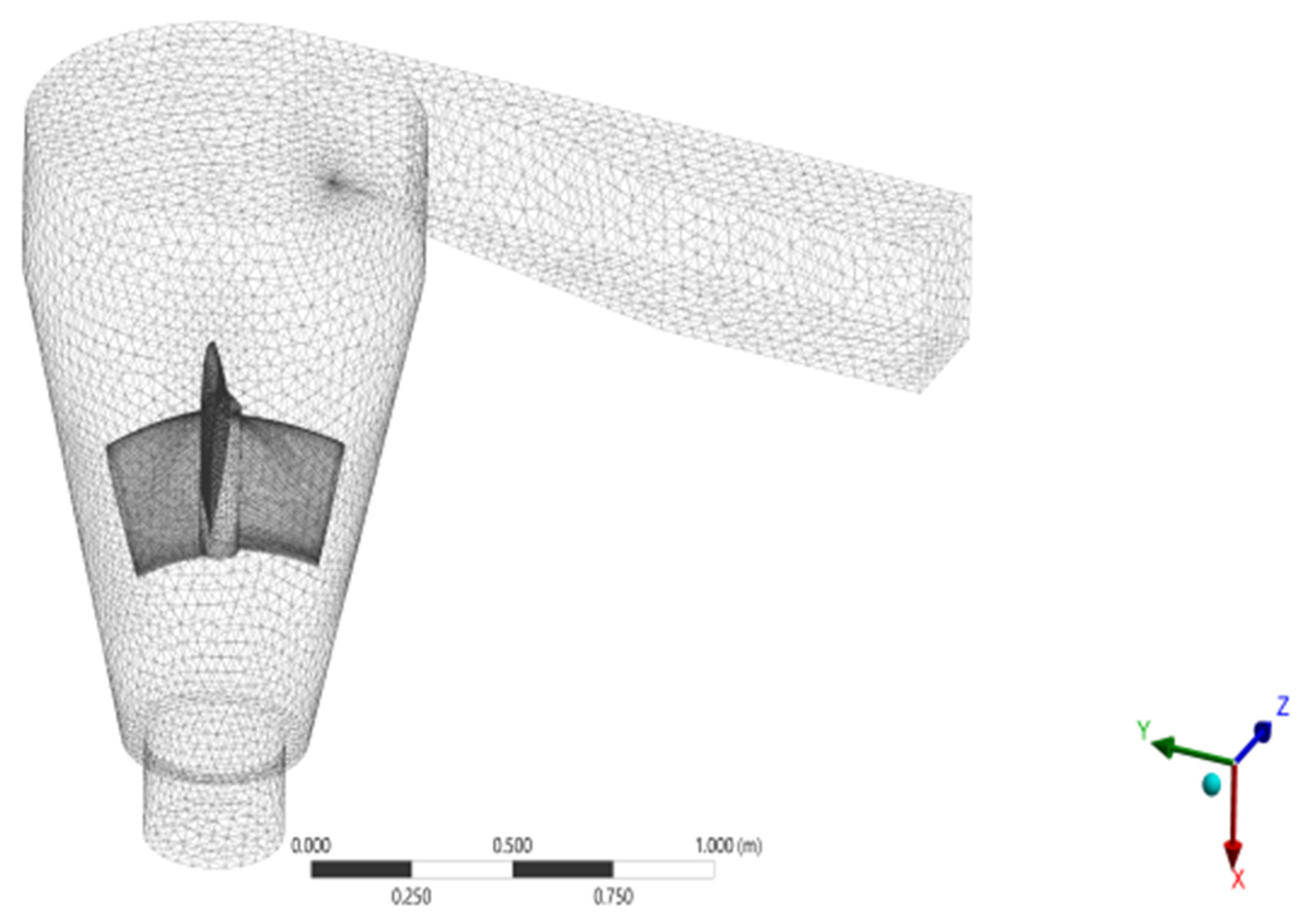
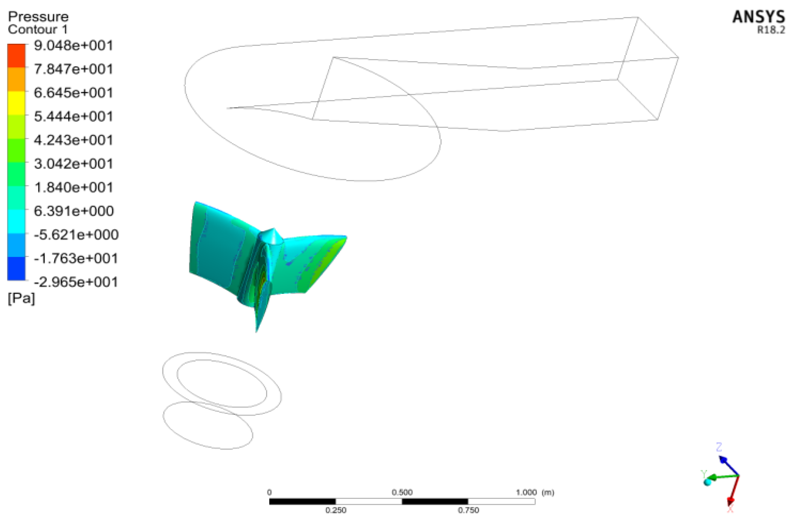
2.2. Computational Model and Discretization Process

Fundamentally, CFD is a finite volume-based numerical technique, in which the control volume (SGVHP) needs to be subdivided into a finite number of small volumes. The accuracy of this process basically depends upon the perfect formation of these sub-volumes. The completed control volume is shown in Figure 8. In general, the formation of sub-volumes follows the structural and linear manner but the presence of the intended object (hydro-rotor) inside the control volume can collapse the structural formation. Due to this unstructured formation of small volumes, the convergence attainments of CFD-based problems are in trouble and thereby the execution of reliable outputs is affected in a severe manner. Therefore, the global and individual set-ups are unavoidable in order to attain a good discretized structure of a control volume [22,23,24,25,26].
In this work, both the SGVHP (control volume) and hydro-rotor (internal object) have equipped complicated design, which drastically reduces the good formation of sub-volumes. Hence the use of global and individual set-ups plays an essential role in the attainment of accrued discretization. Mainly, the curvature and proximity facilities are supported hugely in the execution of good meshes. In the discretization process, the curvature is used to provide the curvy design information of control volume and object to the mesh tool, and thereby the sub-volumes are formed accordingly as per the instruction of curvature representation. Then the other parameters that need to be considered in the mesh set-up arearea variations inside the control volume without the hydro-rotor, in which the proximity facility is used to define the area variations inside the control volume particularly the region between the outer profile of the hydro-rotor with SGVHP profiles. Because of this proximity, the mesh tool easily understands the presence of hydro-rotor and its curvature, and thereby the meshes are formed as per proximity instructions. In this work, fine meshes are generated, in which more than 10 lakhs tetrahedral elements are used to predict this hydrodynamic flow behavior perfectly, which is revealed in Figure 9.

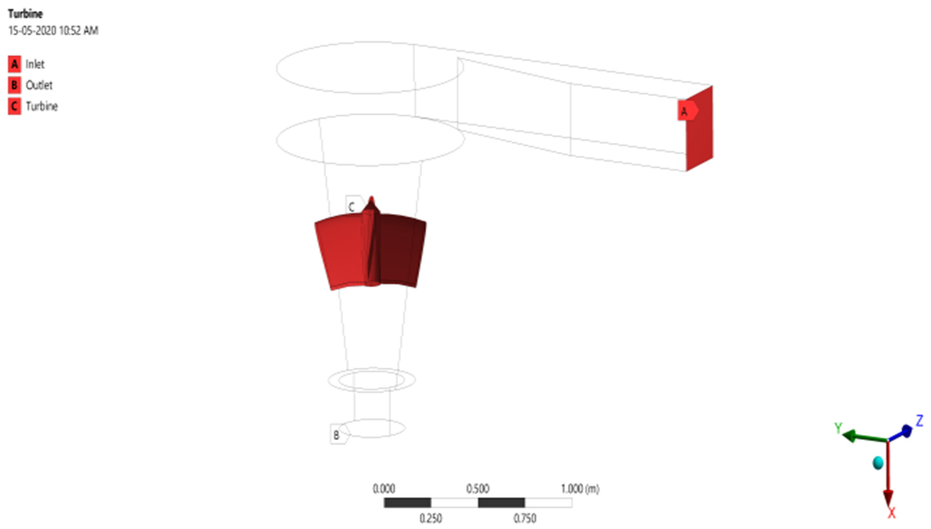
2.3. Boundary Conditions

In general, the procedures involved in the CHA are simple and user-friendly. However, the convergence attainment and thereby the process of achievement of steadfast outputs are the very toughest ones. The density of the working fluid is reasonably high because the probability of vortices formation is low at low-speed operation and medium at high-speed operation. In this work, a low speed of 0.1 m/s is used to analyze the performance of a SGVHP, in which the standard literature survey provided the details of low-speed inlet conditions. As a result of this low-speed condition, the concern provided to take care of turbulence is in the low level only, which made the procedures of CHA easy. Then water material is implemented in this work because of the flexibility of the CFD tool, i.e., ANSYS Fluent. Similarly, the working pressures with respect to depth, viscosity, etc., are employed in the right manner. The complete boundary conditions are shown in Figure 10.

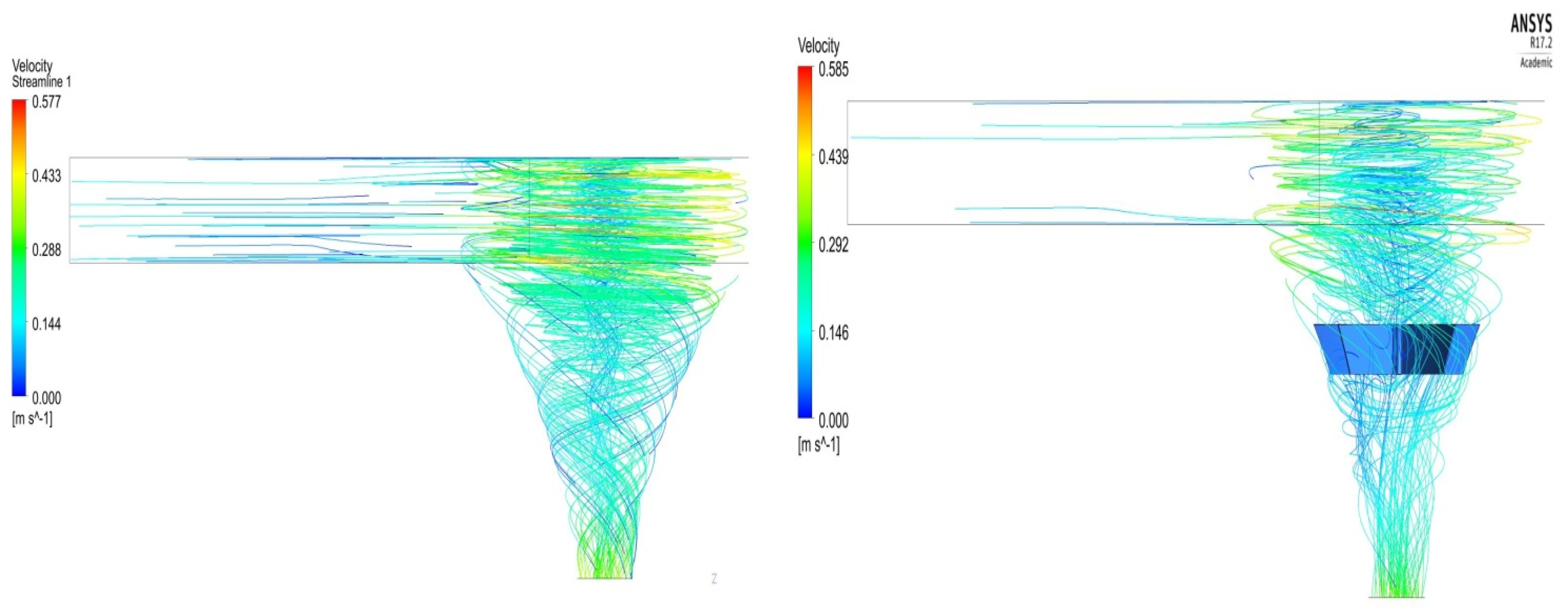
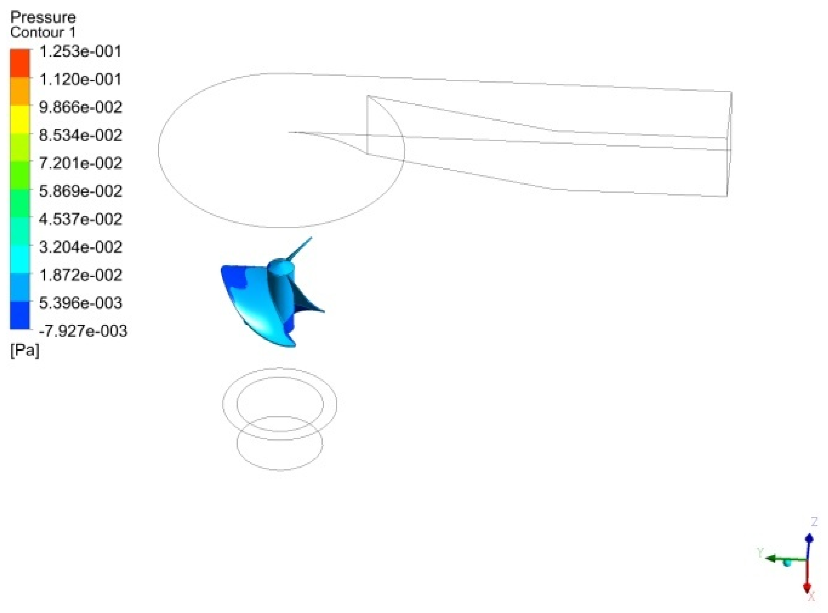
2.4. Details about the Hydrodynamic Analysis

Generally, the water material is incompressible one so the pressure estimation plays a predominant role, and thereby the pressure-based solver is used for the entire analysis. Even though the low-speed operation is applied, the turbulence flow is implemented in this work because of the involvement of the rotodynamic effect of the hydro-rotor and the geometrical nature of an SGVHP. The “k-ε” model is used to represent the turbulence in the entire analysis and it is executed well in the assigned work, which is nothing but the prediction of vortices. Naturally, the SGVHP comes under internal analysis, in which the free slip conditions are provided at the wall of the SGVHP and no-slip conditions are given at the hydro-rotors. Basically, the no-slip condition is nothing but a representation of the frictional behavior of the turbine structure, which is located inside the control volume. Reynolds averaged Navier–Stokes equations primarily contribute to the solution of the CFD, in which the order level of differential equations plays a top role in the provision of an accurate solution. Because of this effect, the second-order-based differential equations are used in all the primary parameters such as pressure, momentum, turbulent kinetic energy, and turbulent dissipation rate. Additionally, the SIMPLE (Semi-Implicit Method for Pressure Linked Equations) based pressure-velocity coupling methodology is used in this work, due to its predominant importance in the estimation fluid properties [21,22,23,24,25,26].

2.5. Governing Equations for Hydrodynamic Analysis

Technically, the governing equations of fluid dynamics are served hugely in the generation of mathematical modeling of computational problems. In addition to that, boundary conditions play a supporting role in mathematical modeling. Generally, the compositional equations in the CFD-based governing equations are continuity equation, momentum equation, and energy equation. The fundamental continuity equation is allotted the number as (20) in this work.
ρ t + ( ρ u ) x + ( ρ v ) y + ( ρ w ) z = 0  
The working nature of the fluid used in GVHP is water, which is incompressible, so the equation is modified and provided in Equation (21).
ρ t + ( u ) x + ( v ) y + ( w ) z = 0  
Additionally, we learned that GVHP-based simulations are steady flow, which means ρ t = 0 , so Equation (21) is further modified and given in Equation (22).
( u ) x + ( v ) y + ( w ) z = 0  
With the help of Equation (22), the pressure variations are estimated inside the GVHP, in which averaged equations and its supported numerical integrations are involved in the fine-tuned attainment of fluid pressure. In GVHP, the fluid velocities are served principally in the execution of the rotational movement of the hydro-rotor so the velocity estimation is a prime task in this work. Scientifically, velocity is an vector quantity so the direction plays a crucial role in its estimation. The conservation of momentum (   F = m a )-based equation provided the platform for the solution of fluid velocities in all directions. Equations (23)–(25) are the momentum relationship in the representations of x, y, and z directions respectively. The momentum equations are derived from Newton’s second law so the forces acting on fluid is predominant one therefore the additional equations are given in order to get the relationship between various stresses, pressures, viscous forces.
ρ g x + σ xx x + τ yx y + τ zx z =   ρ ( u t +   u u x +   v u y + w u z )
ρ g y + τ xy x + σ yy y + τ zy z =   ρ ( v t +   u v x +   v v y + w v z )
ρ g z + τ xz x + τ yz y + σ zz z =   ρ ( w t +   u w x +   v w y + w w z )
where ,   σ xx = p + 2 μ u x ; τ xy =   τ yx =   μ ( u y + v x ) ; σ yy = p + 2 μ v y ; τ yz =   τ zy =   μ ( v z + w y ) ;   σ zz = p + 2 μ w z ; τ zx =   τ xz =   μ ( w x + u z )
The model equation for the turbulent kinetic energy [ k ] is as follows:
Dk Dt = k t + u j ¯ k x j = x j [ v t σ k k x j ] + P ε  
The model equation for the turbulent dissipation [ ε ] is as follows:
D ε Dt = ε t + u j ¯ ε x j = x j [ v t σ g ε x j ] + C g 1 P ε k C g 2 ε 2 k

2.6. Grid Convergence Study

Simply, the grid convergence study is the optimization process of mesh, which is based on its good quality with respect to providing the correct outcome. The principle of this optimization investigation is the estimation of output variations on all the mesh cases and thereby selecting the least quantity of elements based on the tiny variations between the cases, in which the quality is never treated as a compromised one. In this grid optimization, in total six different types of meshes are generated based on theircapturing quality, which are coarse mesh, medium mesh, fine mesh, and fine with face meshes setup on the rotor. The aforesaid boundary conditions are implemented in all the six cases, in which the Model–II rotor-based SGVHP is commonly used for all the cases without any change in any kind or modifications. The first case deals with the coarse mesh set-up, which is revealed in Figure 11. Medium quality-based elements are constructed in Case–II, which is revealed in Figure 12. Apart from these two cases, the advanced two more mesh cases are used in this work, which are fine with face meshes set-up and fine with curvature as well as proximity set-up. All the two best meshes are pictorially revealed in Figure 13 and Figure 14 respectively. The hydro-rotor and GVHP are critical in design thus the proximity and curvature facilities are predominantly used in this work. The comprehensive details of nodes and elements of all the mesh cases are listed in Table 2. Additionally, the computational structural analyses are computed for all the four different mesh-based ModelII with GVHP assigned test set-up, in which, except mesh variations, all other input conditions are the same. The comparative data are revealed in Figure 15, which concluded that Case–III is preferable to use than Case–IV, thus Case–III-based mesh set-ups are used for all the cases.

2.7. Validation Study of Proposed Methodology

Computational analysis is the predominant approach that has been used in this kind of complicated and hydrodynamic-based application. Thus the validation of this implemented computational approach is very important, which is executed in this work through a previously completed experimental study [2]. Convex and concave shape-based SGVHPs were constructed and tested for hydropower generation, and are listed in Table 3 [2]. The completed experimental test data were imposed as per the present authors’ assumption and the same setups are analyzed through the CHA approach in this article. The outer diameter for the concave SGVHP is assumed as 118.109 mm and the outer diameter for the convex GVHP is assumed as 178.164 mm [2]. Figure 16, Figure 17, Figure 18 and Figure 19 reveal the design and fluid simulation results of a convex-shaped SGVHP. The computational results and its computational models are reveal in Figure 20, Figure 21, Figure 22 and Figure 23.
V Induced = r ω   .
Induced   Linear   Velocity = Radius * Angular   Velocity     0.434 = 0.178164 Angular   Velocity
Angular   Velocity = 2.44 rad s = 23.3   RPM
Power = Torque Angular   velocity Power = 0.0103894   23.3 = 0.2421   W  
Induced   Linear   Velocity = Radius Angular   Velocity     0.146 = 0.118109 Angular   Velocity
Angular   Velocity = 1.24 rad s = 11.84   RPM
Power = Torque Angular   velocity     Power = 0.0313967     11.84 = 0.371737   W
Through Table 3, it is strongly observed that the proposed methodology has the full capacity to provide reliable outcomes due to this verified validation.

3. Computational OptimizationResults and Discussions—I

The first and primary optimization of this work dealt with the selection process of suitable design parameters for SGVHP. The selected suitable best parameters for this proposed SGVHP are the outer shape of the SGVHP, notch angle of SGVHP, basin diameter of the SGVHP, and conical angle of SGVHP. The aforesaid boundaries and grid finalizations are implemented in all these comparative cases of hydrodynamic effects. Figure 24 and Figure 25 reveal the velocity distributions inside circular and hexagonal-shaped SGVHPs.

3.1. Optimization of Design Based on Shape through CHA

From Figure 1, it is forcefully observed that basin shape, conical angle, notch angle, and basin diameter predominantly enforce the extraction of a high amount of hydropower from the hydrodynamic environment. Thus, the above-mentioned design factors are clearly investigated in the first optimization, in which the input boundary conditions are input velocity of 0.1 m/s, notch angle of 10 degrees, and the basin diameter is provided as 1000 mm.
The first comparative investigation (Figure 26) is done on the shape of the basin, wherein three shapes are considered: hexagonal, circle, and square. The hydro fluid velocity is increased in the circle-shaped SGVHP, which increases the energy extraction so the same circle shape is shortlisted from the first investigation.

3.2. Optimization of Design Based on SGVHP’s Notch Angle

The second comparative investigation (Figure 27) is executed on the notch angle of GVHP, in which the following notch angles underwent the computational analysis: 11.4°, 12°, 12.5°, 13°, 13.5°, and 14°. The hydro fluid velocity is increased by 45% in the case of the SGVHP modeled with a 13° notch angle, which increases the energy extraction so 13° is picked as the best design parameter for SGVHP.

3.3. Optimization of Design Based on SGVHP’s Basin Diameter

The third comparative investigations (Figure 28 and Figure 29) are computed on the diameter of the basin with the optimized notch angles, wherein seven various diameters are imposed. The hydro fluid velocity is increased in a 1000 mm diameter case so the diameter of the GVHP’s basin is finalized as 1000 mm.

3.4. Optimization of Design Based on SGVHP’s Conical Angle

Figure 30 is comprised of a comprehensive analysis of various conical angles of GVHP. Through this analysis, a suitable conical angle is found which is nothing but 13°. Finally, the following observations are selected: circular shape based GVHP has performed better than other shapes, notch angles of 13° have performed well than other notch angles of GVHPs, basin diameter of 1000 mm has induced high fluid velocity than other GVHP’s diameter, and conical angles of 14° have performed than other conical angles of GVHPs. Therefore the optimized design parameters from the first optimization case are a circular-shaped 1000 mm diameter basin with 13° and 14° notch and conical angles, this GVHP is superior to other design cases.

4. Computational Optimization Results and Discussions—II

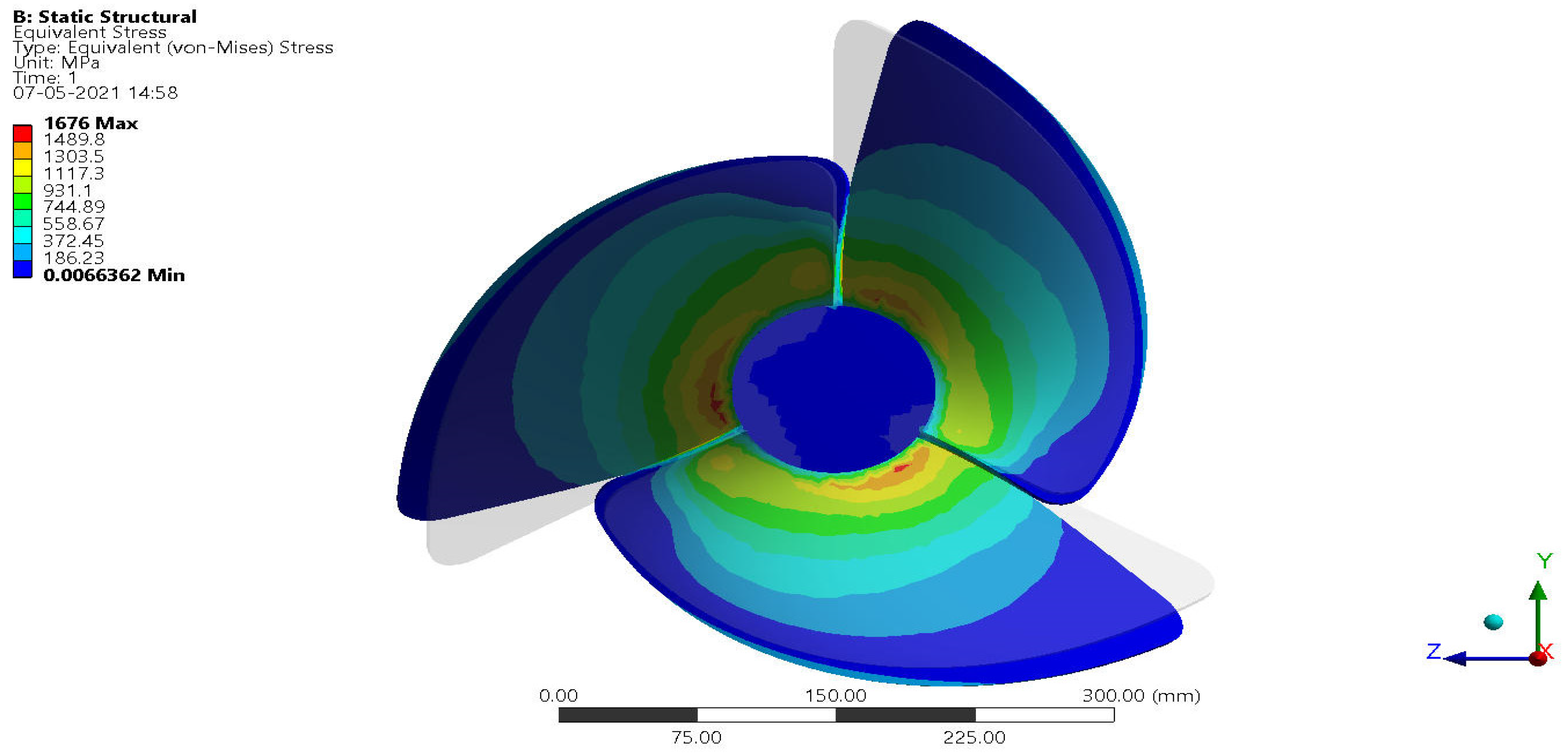
4.1. Optimization of Lightweight for GVHP Rotors

The second optimization of this work dealt with the selection process of a suitable hydro-rotor for GVHP and its perfect lightweight material to withstand high hydrodynamic loads. In this regard, four hydro-rotors are designed and underwent hydrodynamic and hydro–structural simulations. The hydro–structural simulation results of various lightweight materials for Hydro-RotorIII are revealed in Figure 31, Figure 32 and Figure 33. From the comparative analysis (Figure 33), the magnesium alloy and Carbon Fiber Reinforced Polymer (CFRP) uni-directional wet-based composites reacted at very low equivalent stress compared to other lightweight materials, so the aforesaid lightweight materials are picked as the best performer to resist high hydrodynamic loads. Additionally, the same materials can be able to provide longer lifetimes than other materials.

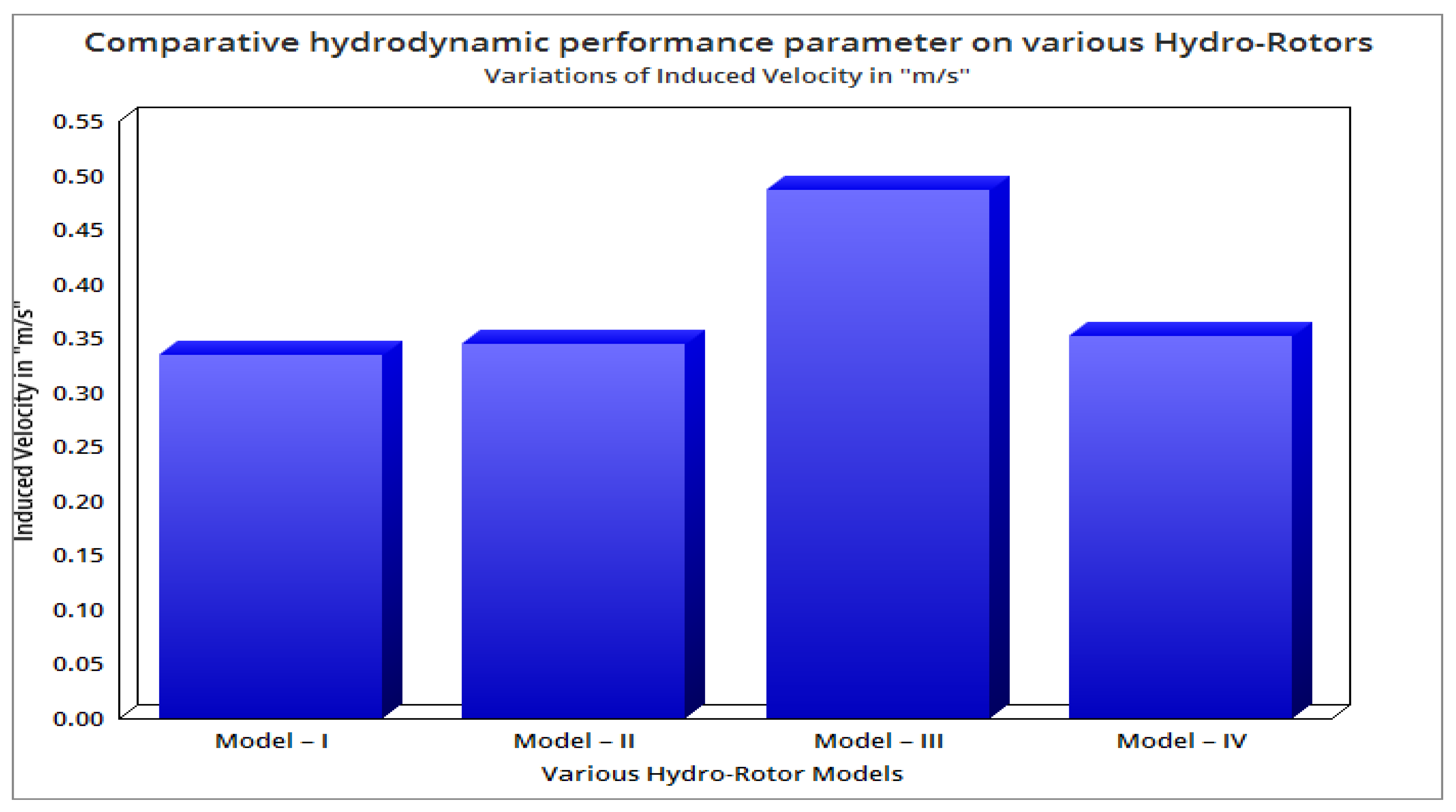
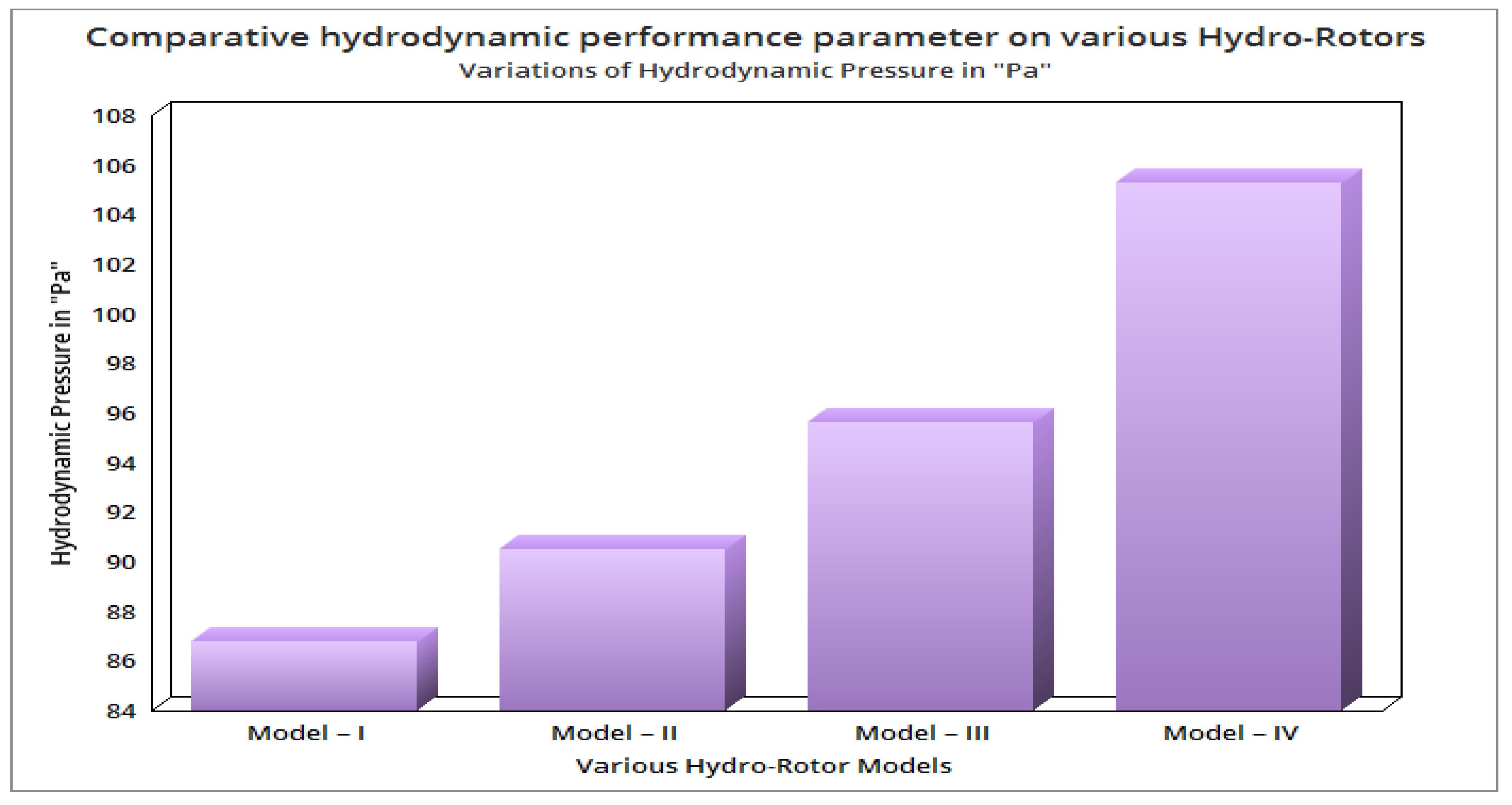
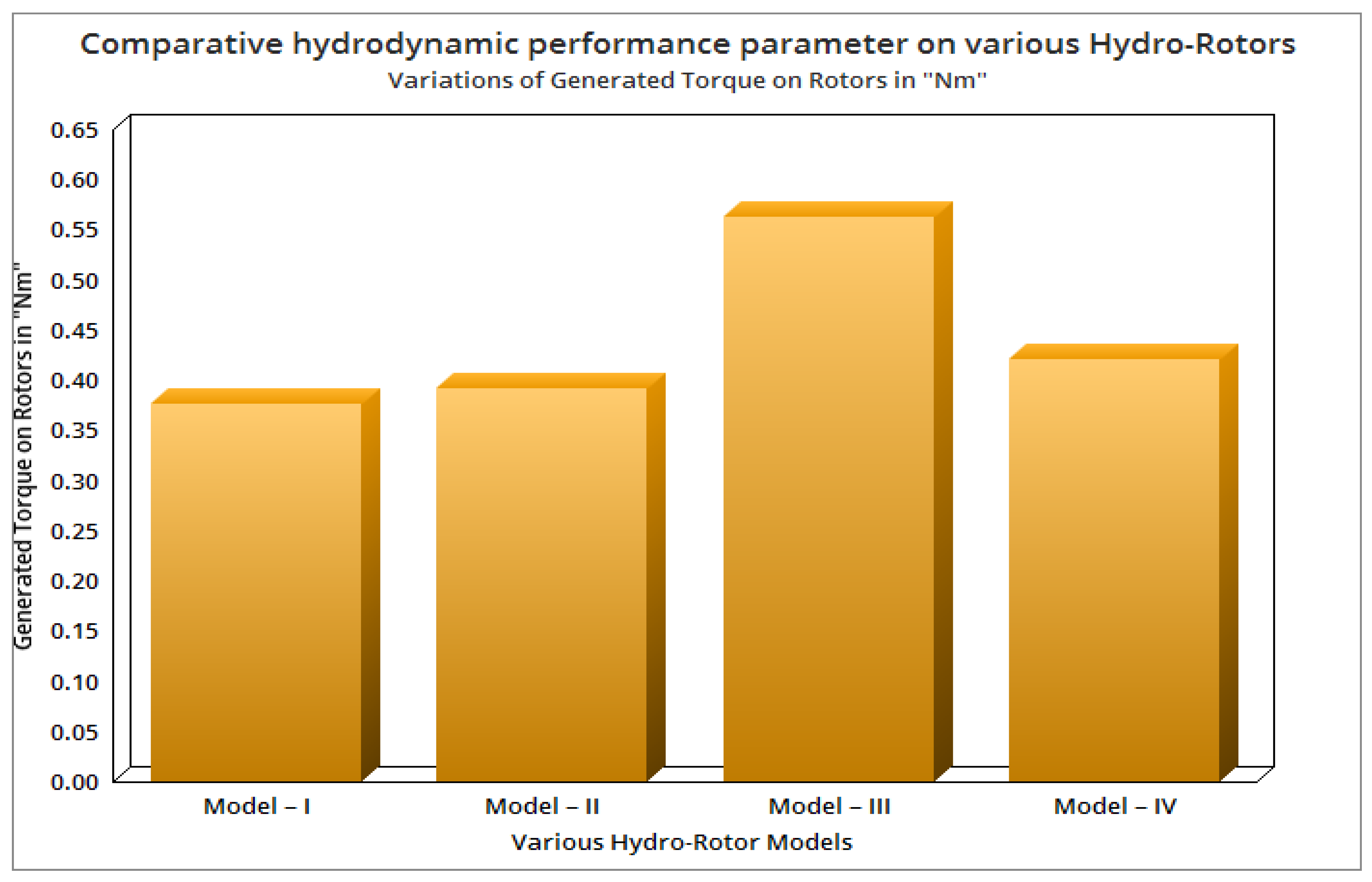
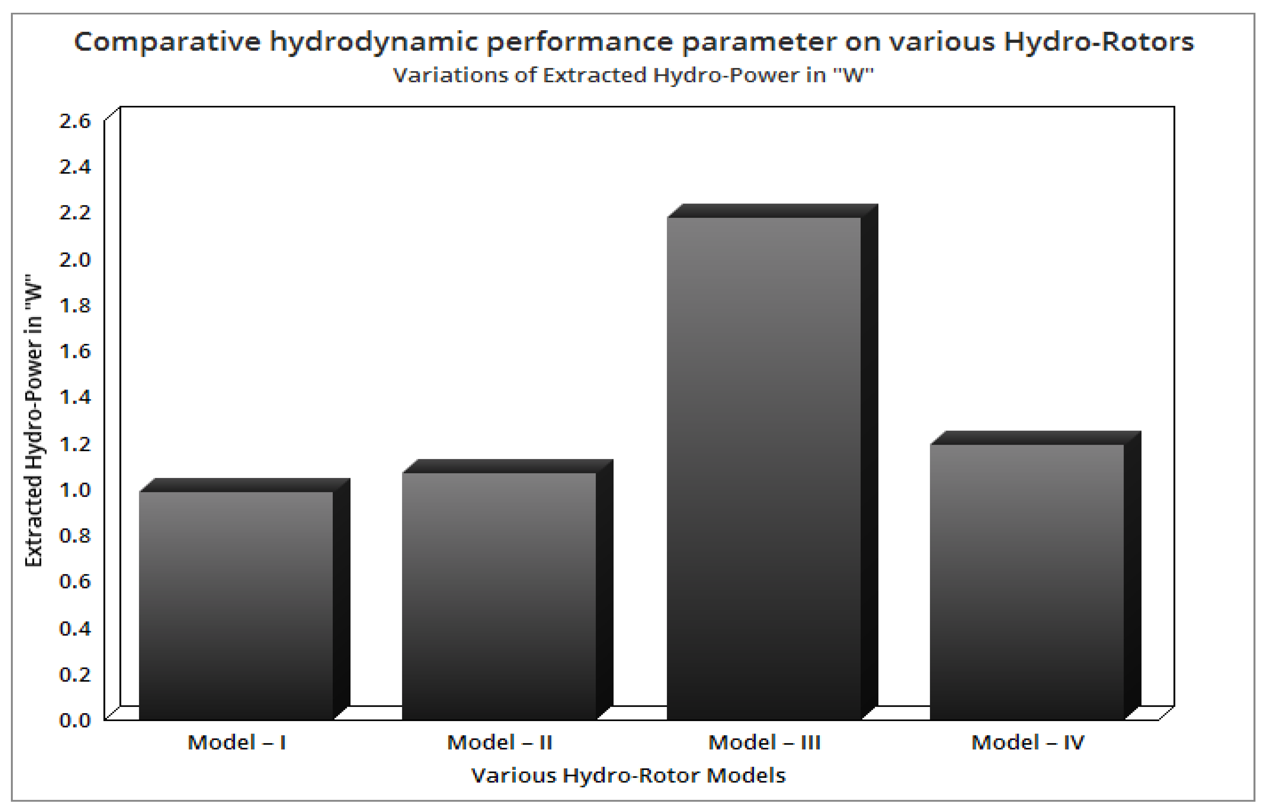
4.2. Optimization of Hydro-RotorsBased on High-Performance Factors

The third optimization was executed based on the high performance of the hydro-rotors. The velocity variations and turbulence formations are clearly revealed in Figure 34 and Figure 35, in which the basic rotor fixed in this case is Hydro-Rotor–I.
The determination of rotational force due to water and pressure variations on Hydro-Rotor–II are shown in Figure 36 and Figure 37, respectively.
The determination of pressure variations on the Hydro-Rotor–III, and velocity representations of working fluid inside the SGVHP are shown in Figure 38 and Figure 39 respectively.
The determination of pressure variations on the Hydro-Rotor–IV and velocity representations of working fluid inside the SGVHP are shown in Figure 40 and Figure 41 respectively. All the analyses are completed and the primary hydrodynamic parameters are comparatively revealed in Figure 42, Figure 43, Figure 44, Figure 45, Figure 46, Figure 47 and Figure 48.
With the help of computational and standard conventional analytical approaches, the various performance factors such as induced velocity by the rotor, hydrodynamic pressure on the rotors, torque given to the rotors, power produced by the rotors, thrust force of rotors, induced rotational velocity of rotors, and propulsive efficiency of the rotors are calculated which are comprehensively revealed in Figure 42, Figure 43, Figure 44, Figure 45, Figure 46, Figure 47 and Figure 48. The analytical formulae involved in this process are given in Equations (30)–(34) [22,25,26].
RPM = V Induced 0.10472 r
P = 2 π N Q 60
P = 1 2 T V Induced [ ( T A V Induced 2   ρ 2 + 1 ) 1 2 + 1 ]
A = π r 2
ƞ Propulsive = 2 1 + ( T A V Induced 2 ρ 2 + 1 )
The hydrodynamic and hydrostatic pressures are cumulatively predicted through ANSYS Fluent and comparatively revealed in Figure 42. The predominant selection outcomes of hydro-rotors are torque generation, rotational velocity, extracted hydropower, and thrust force are carefully computed and revealed in Figure 43, Figure 44, Figure 45 and Figure 46, respectively.
Figure 47 shows the proportional outcome of propulsive efficiency of all the hydro-rotors. From the comparative Figure 41, Figure 42, Figure 43, Figure 44, Figure 45, Figure 46 and Figure 47, it is clearly understood that Model–III is extracting a high amount of energy from hydro medium thus the proposed GVHP is planned to equip Model–III-based rotors in future applications. Finally, it is inferred that Model–III-based hydro-rotors are more preferable to use in the GVHP because they performed better than other hydro-rotor models.

5. Conclusions

The conceptual designs of all the four hydro-rotor models are executed with the help of CATIA, in which the dimensions of GVHP and various rotors are obtained from the previous reference papers. In total, four different models are used in this work, which are thin and slim rotors (Model–I), rotors based on aerofoil shape (Model–II), Savonius rotors (Model–IV), and high twisted blade profile-based rotors (Model–IV). The separate analyses were executed in order to estimate the optimized location in the GVHP, which has the capability to provide a high number of rotational velocities. Through that comprehensive analysis, the following observations are noted: the circular shape-based GVHP performed better than other shapes, notch angles of 13° degree have performed better than other notch angles of GVHPs, a basin diameter of 1000 mm has induced higher fluid velocity than other GVHP diameters, and conical angles of 14° have performed better than other conical angles of GVHPs. Therefore the optimized design parameters from the first optimization case are a circular-shaped 1000 mm diameter basin and 13° degree and 14° degree notch and conical angles. The numerical tool, i.e., ANSYS Fluent is used for the estimation of rotational velocity of water, torque on the various rotor, and power extracted from turbines, in which all the four models equipped with GVHP are discretized with fine mesh set-up. Finally, Model–III is more suitable to extract high torque and power estimations from a GVHP set-up; thus the same model is recommended for hydropower applications. Finally, the lightweight material-based selection is computed through the help of an HSI simulation, wherein the suitable material to resist hydrodynamic load is obtained, which is magnesium alloy. Additionally, GFRP-Woven-FR-4 also reacted with low structural outcomes next to Mg alloy so the just said GFRP composite is also preferable to implement in real-time hydropower applications.

Author Contributions

Conceptualization, V.R., A.P.R. and H.A.Z.A.-b.; methodology, V.R., R.M., S.R., A.P.R. and F.W.; software, V.R., R.M. and H.A.Z.A.-b.; validation, V.R., Y.J. and H.A.Z.A.-b.; formal analysis, V.R., R.M. and F.W.; investigation, V.R. and R.M.; resources, R.M. and H.A.Z.A.-b.; data curation, V.R., H.A.Z.A.-b. and F.W.; writing—original draft preparation S.R., V.R., R.M. and H.A.Z.A.-b.; writing—review and editing, V.R., A.P.R. and Y.J.; visualization V.R., R.M. and Y.J.; supervision, F.W., H.A.Z.A.-b. and Y.J.; project administration, A.P.R., R.M. and Y.J. All authors have read and agreed to the published version of the manuscript.

Funding

This research received no external funding.

Institutional Review Board Statement

Not applicable.

Informed Consent Statement

Not applicable.

Data Availability Statement

Not applicable.

Conflicts of Interest

The authors declare that they have no competing interests.

References

  1. Jha, A.K.; Subedi, D.U.; Timilsina, A.B. Assessment of Gravitational Water Vortex Hydropower Plant in Nepal. Int. Res. J. Eng. Technol. 2018, 5, 2679–2691. [Google Scholar]
  2. Sánchez, A.R.; Del Rio, J.A.S.; Muñoz, A.J.G.; Montoya, J.A.P. Numerical and Experimental Evaluation of Concave and Convex Designs for Gravitational Water Vortex Turbine. J. Adv. Res. Fluid Mech. Therm. Sci. 2019, 64, 160–172. [Google Scholar]
  3. Thapa, D.; Mishra, A.; Sarath, K.S. Effect of inlet geomentory in the Quality of vortex formed using Vortex flow channel. Int. J. Mech. Eng. Technol. 2017, 8, 515–524. [Google Scholar]
  4. Power, C.; McNabola, A.; Coughlan, P. A Parametric Experimental Investigation of the Operating Conditions of Gravitational Vortex Hydropower (GVHP). J. Clean Energy Technol. 2015, 4, 112–119. [Google Scholar] [CrossRef] [Green Version]
  5. Sreerag, S.R.; Raveendran, C.K.; Jinshah, B.S. Effect of Outlet Diameter on the Performance of Gravitational Vortex Turbine with Conical Basin. Int. J. Sci. Eng. Res. 2016, 7, 457–463. [Google Scholar]
  6. Dhakal, S.; Nakarmi, S.; Pun, P.; Thapa, A.B.; Bajracharya, T.R. Development and Testing of Runner and Conical Basin for Gravitational Water Vortex Power Plant. J. Inst. Eng. 2014, 10, 140–148. [Google Scholar] [CrossRef] [Green Version]
  7. Wanchat, S.; Suntivarakorn, R.; Wanchat, S.; Tonmit, K.; Kayanyiem, P. A Parametric Study of a Gravitation Vortex Power Plant. Adv. Mater. Res. 2013, 805–806, 811–817. [Google Scholar] [CrossRef]
  8. Anjali Mohanan, M. Power Generation with Simultaneous Aeration using a Gravity Vortex Turbine. Int. J. Sci. Eng. Res. 2016, 7, 19–24. [Google Scholar]
  9. Arul Prakash, R.; Vijayanandh, R. Design Optimization of Convergent—Divergent Nozzle Using Computational Fluid Dynamics Approach. Int. J. Mech. Prod. Eng. Res. Dev. 2019, 9, 220–232. [Google Scholar]
  10. Shabaraa, H.M.; Yaakoba, O.B.; Yasser, M.; Ahmeda, Y.M.; Elbatrana, A.H. CFD Simulation of Water Gravitation Vortex Pool Flow for Mini Hydropower Plants. J. Sci. Eng. 2015, 74, 77–81. [Google Scholar]
  11. Rahman, M.M.; Tan, J.H.; Fadzlita, M.T.; Wan KhairulMuzammil, A.R. A Review on the Development of Gravitational Water Vortex Power Plant as Alternative Renewable Energy Resources. In Proceedings of the international Conference on Materials Technology and Energy, Materials Science and Engineering, Miri, Malaysia, 20–21 April 2017; p. 217. [Google Scholar]
  12. Yaakob, O.; Ahmed, Y.; Elbatran, A.H.; Shabara, H.M. A Review on Micro Hydro Gravitational Vortex Power and Turbine Systems. J. Teknol. 2014, 69. [Google Scholar] [CrossRef] [Green Version]
  13. Dhakal, S.; Timilsina, A.B.; Dhakal, R.; Fuyal, D.; Bajracharya, T.R.; Pandit, H.P. Effect of Dominant Parameters for Conical Basin: Gravitational Water Vortex Power Plant. In Proceedings of the International Conference on Technology and Innovation Management & IOE Graduate Conference, Kathmandu, Nepal, 4 October 2014. [Google Scholar] [CrossRef]
  14. Ersoy, S. Vortex with the Formation of Electricity Generation and System Modelling. Int. J. Environ. Sci. Dev. 2014, 5, 152–154. [Google Scholar] [CrossRef] [Green Version]
  15. Müller, S.; Cleynen, O.; Hoerner, S.; Lichtenberg, N.; Thévenin, D. Numerical analysis of the compromise between power output and fish-friendliness in a vortex power plant. J. Ecohydraulics 2018, 3, 86–98. [Google Scholar] [CrossRef]
  16. Kueh, T.C.; Beh, S.L.; Ooi, Y.S.; Rilling, D.G. Experimental study to the influences of rotational speed and blade shape on water vortex turbine performance. J. Phys. Conf. Ser. 2017, 822, 12066. [Google Scholar] [CrossRef] [Green Version]
  17. Nishi, Y.; Inagaki, T. Performance and Flow Field of a Gravitation Vortex Type Water Turbine. Int. J. Rotating Mach. 2017, 2017, 2610508. [Google Scholar] [CrossRef]
  18. Vijayakumar, M.; Vijayanandh, R.; Ramesh, M.; Senthil Kumar, M.; Raj Kumar, G.; Sivaranjani, S.; Jung, D.W. Conceptual Design and Numerical analysis of an Unmanned Amphibious Vehicle. In Proceedings of the AIAA Scitech2021 Forum, Online, 11–15 & 19–21 January 2021. [Google Scholar]
  19. Salazar-Marín, E.A.; Rodríguez-Valencia, A.F. Design, assembly and experimental tests of a Savonius type wind turbine. Sci. Technol. 2019, 24, 397–407. [Google Scholar] [CrossRef]
  20. Kumar, M.S.; Krishnan, A.S.; Vijayanandh, R. Computational, Experimental and Surface Characterisation of Glass Fibre Reinforced Plastic Composite for Wind Turbine Blade Application. J. Environ. Prot. Ecol. 2021, 22, 602–616. [Google Scholar]
  21. Carlton, J.S. Marine Propellers and Propulsion, 2nd ed.; Butterworth-Heinemann: Oxford, UK, 2007; Volume 12, pp. 435–458. ISBN 978-07506-8150-6. [Google Scholar]
  22. Vijayanandh, R.; Kumar, M.S.; Rahul, S.; Thamizhanbu, E.; Jafferson, M.D.I. Conceptual Design and Comparative CFD Analyses on Unmanned Amphibious Vehicle for Crack Detection. Int. Conf. Unmanned Aer. Syst. Geomat. 2020, 51, 133–149. [Google Scholar] [CrossRef]
  23. Praveen Kumar, V.; Kishor Kumar, S.; Sankaresh Pandian, K.R.; Ashraf, E.; Thanga Tamil Selvan, K.; Vijayanandh, R. Conceptual Design And Hydrodynamic Research On Unmanned Aquatic Vehicle. Int. J. Innov. Technol. Explor. Eng. 2019, 8 (Suppl. 11), 121–127. [Google Scholar] [CrossRef]
  24. Vijayanandh, R.; Kiran, P.; Prasanth, S.I.; Kumar, G.R.; Balaji, S. Conceptual Design and Optimization of Flexible Landing Gear for Tilt-Hexacopter Using CFD; Springer: Cham, Switzerland, 2020; pp. 151–174. [Google Scholar] [CrossRef]
  25. Raja, V.; Solaiappan, S.K.; Rajendran, P.; Madasamy, S.K.; Jung, S. Conceptual Design and Multi-Disciplinary Computational Investigations of Multirotor Unmanned Aerial Vehicle for Environmental Applications. Appl. Sci. 2021, 11, 8364. [Google Scholar] [CrossRef]
  26. Vijayanandh, R.; Venkatesan, K.; Kumar, R.R.; Kumar, M.S.; Jagadeeshwaran, P. Theoretical and Numerical Analyses on Propulsive Efficiency of Unmanned Aquatic Vehicle’s Propeller. J. Phys. Conf. Ser. 2020, 1504, 12004. [Google Scholar] [CrossRef]
Figure 1. GVHP with component names.
Sustainability 14 00727 g001
Figure 2. Dimensions of the conceptual design of SGVHP with Hydro-Rotor-I.
Sustainability 14 00727 g002
Figure 3. Conceptual design of Hydro-RotorII.
Sustainability 14 00727 g003
Figure 4. A typical combined view of SGVHP with Hydro-RotorII.
Sustainability 14 00727 g004
Figure 5. Conceptual design of SGVHP with Hydro-Rotor–III.
Sustainability 14 00727 g005
Figure 6. Dimensions of the conceptual design of Hydro-Rotor–IV.
Sustainability 14 00727 g006
Figure 7. A typical combined view of SGVHP with Hydro-Rotor–IV—wireframe model.
Sustainability 14 00727 g007
Figure 8. A typical combined view of SGVHP with hydro-rotor.
Sustainability 14 00727 g008
Figure 9. A discretized structure of SGVHP (control volume).
Sustainability 14 00727 g009
Figure 10. Typical view of boundary conditions on GVHP.
Sustainability 14 00727 g010
Figure 11. A typical view of coarse mesh.
Sustainability 14 00727 g011
Figure 12. A typical wireframe view of medium mesh.
Sustainability 14 00727 g012
Figure 13. Fine mesh set-up.
Sustainability 14 00727 g013
Figure 14. Fine face mesh set-up.
Sustainability 14 00727 g014
Figure 15. Comprehensive data of grid convergence investigation.
Sustainability 14 00727 g015
Figure 16. Design draft of hydro-rotor for convex-shaped SGVHP.
Sustainability 14 00727 g016
Figure 17. Design draft of convex-shaped SGVHP.
Sustainability 14 00727 g017
Figure 18. Isometric view of convex-shaped SGVHP.
Sustainability 14 00727 g018
Figure 19. Hydrodynamic velocity variations inside the GVHP, with and without rotors.
Sustainability 14 00727 g019
Figure 20. Design draft of hydro-rotor concave-shaped SGVHP.
Sustainability 14 00727 g020
Figure 21. Design draft of concave-shaped SGVHP.
Sustainability 14 00727 g021
Figure 22. Isometric view of concave-shaped SGVHP.
Sustainability 14 00727 g022
Figure 23. Hydrodynamic velocity variations inside the concave SGVHP with and without rotors.
Sustainability 14 00727 g023
Figure 24. Hydrodynamic analysis in circular shape-based SGVHP.
Sustainability 14 00727 g024
Figure 25. Hydrodynamic analysis in hexagonal shape-based GVHP.
Sustainability 14 00727 g025
Figure 26. Comprehensive outcome of induced fluid velocity—design optimization–I.
Sustainability 14 00727 g026
Figure 27. Comparative analyses of notch angle versus rotational velocities.
Sustainability 14 00727 g027
Figure 28. Comparative analysis of basin diameter with fixed notch angle of 11.4°.
Sustainability 14 00727 g028
Figure 29. Comparative analysis of basin diameter with fixed notch angle of 13°.
Sustainability 14 00727 g029
Figure 30. Comprehensive data of GVHP with various cone angles.
Sustainability 14 00727 g030
Figure 31. Equivalent stress variations of Rotor–IV made up of magnesium alloy.
Sustainability 14 00727 g031
Figure 32. Equivalent stress variations of Rotor–IV made up of CFRP-UD-wet.
Sustainability 14 00727 g032
Figure 33. Comprehensive equivalent stress variations of Rotor-IV for different materials.
Sustainability 14 00727 g033
Figure 34. Pressure variations on Hydro-Rotor–I.
Sustainability 14 00727 g034
Figure 35. Velocity variations inside the optimized SGVHP with Hydro-RotorI.
Sustainability 14 00727 g035
Figure 36. Estimations of torque on the optimized SGVHP Hydro-RotorII.
Sustainability 14 00727 g036
Figure 37. Pressure variations on Hydro-RotorII.
Sustainability 14 00727 g037
Figure 38. Pressure variations on Hydro-RotorIII.
Sustainability 14 00727 g038
Figure 39. Velocity variations inside the optimized SGVHP with Hydro-RotorIII.
Sustainability 14 00727 g039
Figure 40. Velocity variations inside the optimized GVHP with Hydro-Rotor–IV.
Sustainability 14 00727 g040
Figure 41. Pressure variations on the Hydro-RotorIV.
Sustainability 14 00727 g041
Figure 42. Comparative variations of induced velocity in m/s.
Sustainability 14 00727 g042
Figure 43. Comparative variations of hydrodynamic pressure in Pa.
Sustainability 14 00727 g043
Figure 44. Comparative variations of generated torque in Nm.
Sustainability 14 00727 g044
Figure 45. Comparative variations of induced rotational velocities in RPM.
Sustainability 14 00727 g045
Figure 46. Comparative variations of extracted hydropower in W.
Sustainability 14 00727 g046
Figure 47. Comparative variations of generated thrust in N.
Sustainability 14 00727 g047
Figure 48. Comparative variations of propulsive efficiency in %.
Sustainability 14 00727 g048
Table 1. List of symbols and notations.
SymbolMeaning
V Hydrostatic Hydrostatic velocity (m/s)
DDiameter of the hydro-rotor (m)
rRadius of the hydro-rotor (m)
r S Sectional radius of the hydro-rotor (m)
P P Pitch of the hydro-rotor (m)
θ Pitch angle (degree)
C L Coefficient of lift of hydro-rotor (no unit)
bChord length of the hydro-rotor (m)
NAngular velocity (RPM)
QTorque of the rotor (Nm)
PPower extracted by the rotor (watts)
TThrust force (Newtons)
AArea of the hydro-rotor (m2)
ρDensity of ocean water (1025 kg/m3)
V Induced Induced velocity (m/s)
PDeliverDelivered power (watts)
VmsaMean speed of advance (m/s)
BpPower coefficient (no unit)
λOptimumHydro-rotor speed coefficient(no unit)
DOptimumOptimum diameter of the hydro-rotor (m)
nNumber of blades in hydro turbine (no unit)
A E A O Expanded area ratio (no unit)
λ A Tip ratio (no unit)
αAAngle of attack (degree)
ω Rotational velocity (rad/s)
eOverlap distance (m)
dDiameter of the single blade (m)
hHeight of the hydro-rotor (m)
D 0 Endplate diameter (m)
PHHydropower (watts)
ASSwept area of the Savonius hydro-rotor (m2)
Table 2. Comparative statistical data of all the mesh cases.
Mesh CasesType of MeshNodesElements
1Coarse82,391452,032
2Medium86,525473,892
3Fine94,475514,421
4Fine with face mesh on turbine95,894514,665
5Fine with inflation on turbine123,100985,742
6Fine with face mesh and inflation on turbine187,5421,412,566
Table 3. Comprehensive results of hydropower generation [2].
Design DetailsExperimental Result Computational ResultError Percentage
Convex–GVHP0.23 W0.24214.99
Concave–GVHP0.37 W0.3717370.47
Publisher’s Note: MDPI stays neutral with regard to jurisdictional claims in published maps and institutional affiliations.

