Article

Mechanical and Shape Memory Properties of 3D-Printed Cellulose Nanocrystal (CNC)-Reinforced Polylactic Acid Bionanocomposites for Potential 4D Applications

by
Victor Chike Agbakoba
1,2,
Percy Hlangothi
2,
Jerome Andrew
3 and
Maya Jacob John
1,2,*
1
Centre for Nanostructures and Advanced Materials, Chemicals Cluster, Council for Scientific and Industrial Research (CSIR), Pretoria 0001, South Africa
2
Department of Chemistry, Nelson Mandela University, Port Elizabeth 6001, South Africa
3
Biorefinery Industry Development Facility, Council for Scientific and Industrial Research (CSIR), Durban 4041, South Africa
*
Author to whom correspondence should be addressed.
Sustainability 2022, 14(19), 12759; https://doi.org/10.3390/su141912759
Submission received: 6 September 2022 / Revised: 4 October 2022 / Accepted: 5 October 2022 / Published: 7 October 2022
(This article belongs to the Special Issue Performance Enhancement and Sustainable Application of Cellulose)

Abstract

:
There is a growing need for diversified material feedstock for 3D printing technologies such as fused deposition modelling (FDM) techniques. This has resulted in an increased drive in the research and development of eco-friendly biopolymer-based composites with wide applications. At present, bionanocomposites of polylactic acid (PLA), biopolymer, and cellulose nanocrystals (CNCs) offer promising technical qualities suitable for FDM 3D printing applications due to their biodegradability and wide-ranging applications. In this work, the applicability of the PLA/CNCs bionanocomposites in 4D applications was investigated by studying its shape-recovery behaviour. Tensile and dynamic mechanical analysis (DMA) was used to elucidate the mechanical and flexural properties of the 3D-printed specimens. The results revealed improvement in the deflection temperature under load (DTUL), creep deformation, and recovery of the PLA/CNCs bionanocomposites. Tensile and static 3-point bending analyses of the bionanocomposites revealed improved tensile strength and modulus of the 3D printed parts. The potential 4D application of the PLA/CNCs bionanocomposites was also investigated by successfully printing PLA/CNC bionanocomposites directly onto a nylon fabric. The PLA/CNCs-fabric prototype included a foldable cube and grid-patterned designs. Additionally, the heat-induced shape memory behaviour of these prototypes was demonstrated.

1. Introduction

Recently, the additive manufacturing technique which involves the three-dimensional (3D) printing of stimulus responsive four-dimensional (4D) objects has gained increased attention. The fabrication of dynamic 4D objects with reconfigurable functionalities finds potential applications in the automotive, biomedical devices, smart textiles, aerospace, and robotics fields [1,2,3,4]. The upsurge in production of 4D objects coincides with the increasing availability of feedstock materials and advancements in additive manufacturing (AM) techniques. Most 4D objects are made using shape memory polymers (SMPs) [5,6] and shape memory alloys (SMAs) [7,8]. Upon fabrication, SMPs and SMAs are manipulated into ‘fixed’ shapes capable of returning to their original form when triggered by an external stimulus such as heat [6], light, humidity [9], solvent [10], and magnetic and electrical fields [11,12].
Shape memory polymers (SMPs) need to possess at least two distinct structural phases to enable it to function as a dynamic 4D material [13]. The first phase is rigid netpoints existing within the bulk network structure of the SMP, often described as the “non-sensitive phase” which stores the memory of the permanent shape, whilst the other “switching phase” allows for stimulus-related transitions [11]. The non-sensitive phase controls the shape recovery from the ‘temporary-fixed’ shape back to the permanent shape. Typically, the non-sensitive netpoints are either crystalline regions in thermoplastics or points of covalent cross-links in thermosets, whereas the stimulus-related transitions of the switching phase allows for the reconfiguration of the SMP into a temporary shape [14]. Collectively, both phases account for the strain deformation of SMPs into reversible structures. Examples of SMPs include cross-linked polyethylene, trans-polyisoprene, acrylate-based polymers, polynorbornene, polyurethanes, and epoxy-based polymers [15]. However, thermoplastic polyurethane (TPU) and TPU-based composites are the most widely reported SMP materials [15,16,17].
The drive for more sustainable materials has encouraged the adoption of biobased polymers as SMPs. The aliphatic polyester, polylactic acid (PLA), is a viable shape memory polymer due to its semi-crystallinity, biodegradability, durability, biocompatibility, high stiffness, and 3D printability [18,19,20,21,22]. The amorphous domain of PLA serves as the “switching phase”, as it can be transformed from a hard glass state to a soft rubbery state above its glass transition temperature (Tg). The crystalline domains function as the “non-sensitive” phase [6,23]. This makes it possible for PLA to be formed into permanent structures, reconfigured into temporary shapes by heating above Tg, and reverted to its original shape by the application of heat [21]. However, the high stiffness, poor melt strength, slow crystallization, and brittle nature of PLA greatly affects its applicability as an SMP, thus necessitating the modification of PLA [24,25]. To achieve this, several methods have been reported such as blending PLA with other polymers [26,27,28], the addition of cellulose nanocrystals (CNCs) [29] and cellulose nanofibers (CNF) [29,30], and the use of plasticizers [25,31].
Recently, the fused deposition modelling (FDM) 3D-printing technique has gained widespread use in the processing of shape memory polymers (SMPs). Most FDM 3D printers fabricate complex objects via a layer-by-layer deposition of molten thermoplastic-based filaments following a pre-programmed pathway [32]. For instance, Leist. S. K. et al. (2017) [21] investigated the effects of temperature and material thickness on the shape memory properties of FDM 3D-printed PLA cantilevers and reported two key findings. Firstly, the PLA shape recovery process occurred faster when the specimen was exposed to higher temperatures (>70 °C); secondly, increasing the material thickness reduced the final percentage of shape recovery. Senatov F.S. et al. (2017) [19] demonstrated the shape memory effect of FDM 3D-printed scaffolds suitable for self-fitting implants using PLA filaments reinforced with bio-resorbable hydroxyapatite (HA). They reported improved shape memory properties, which was attributed to the HA acting as additional rigid netpoints in the scaffolds. Furthermore, Sun Y.-C. et al. (2019) [25] studied the effect of plasticizer on the shape memory effect of 3D-printed PLA objects. Yang Z. et al. (2021) [33] used extrusion-based 3D printing to fabricate bean-pod-structured octadecane phase change microlattices encapsulated in a highly interconnected graphene network for high-performance solar thermal energy harvesting and storage. However, few studies have reported the FDM 3D printing of cellulose nanocrystal (CNC)-reinforced PLA bionanocomposites for SMP applications.
In this study, we investigated the potential application of cellulose nanocrystal (CNC)-reinforced polylactic acid (PLA) bionanocomposites in 4D applications. The bionanocomposite filament was previously prepared by melt mixing and single-screw extrusion of semi-crystalline PLA and freeze-dried CNC. The major problem faced during the production of bionanocomposites are mainly related to feeding the CNC fibres during melt mixing, dispersion issues, increased brittleness, and poor interfacial compatibility. So, we adopted a combination of strategies to resolve these issues. Firstly, the freeze-dried CNC was redispersed in a solution of polar protic and aprotic solvents and was directly liquid-fed into the molten PLA during melt mixing. Food grade additives, which include polyethylene glycol (PEG), triacetin (TA), and an epoxy-based styrene-acrylic multifunctional chain extender, were added to improve processability, flexibility, and compatibility between the matrix (PLA) and the reinforcing (CNC) components. Afterwards, the PLA/CNC bionanocomposites were processed using a fused deposition modelling (FDM) 3D printer to fabricate specimens for shape memory analysis. The heat-induced shape recovery behaviour, fracture morphology, flexural, and mechanical properties of the 3D-printed bionanocomposites were investigated using dynamic mechanical analysis (DMA), tensile analysis, and scanning electron microscopy (SEM). Furthermore, we investigated the potential 4D applications of the PLA/CNC bionanocomposite by directly printing it onto a nylon–spandex fabric. This material can be used in applications where the flex and breathability of the fabric would provide comfort, whilst the PLA/CNC provides rigidity, support, and shape memory behaviour. In this study, we have successfully printed two design patterns (cross and grid) onto a stretchable fabric to explore such potential applications. The adhesion between the fabric and the 3D-printed bionanocomposites was haptically and visually evaluated. Afterwards, we attached wearable electronics with pulse rate sensing capabilities to further demonstrate potential applicability.

2. Materials and Methods

The four filaments used in this study were produced in-house using fibre-grade polylactic acid (IngeoTM PLA6202D, semi-crystalline Mw = 97 kDa, and <2% D-lactide) (NatureWorks, Minnetonka, MN, USA). Polyethylene glycol, triacetin, and a food-safe styrene-acrylic multifunctional chain extender (Joncryl ADR-436-C) were added to improve flexibility, processability, and melt strength.
The freeze-dried cellulose nanocrystals (CNC) used in this current study were extracted on a pilot scale from sawdust of Eucalyptus grandis by chemical means, using a propriety technology developed by the CSIR Biorefinery Industry Development Facility (BIDF), Durban, South Africa.

2.1. Summary of Filament Production

A single-screw extruder was used to obtain PLA/CNC filaments suitable for FDM 3D printing applications. The freeze-dried CNC was redispersed in green solvents (acetone, ethanol, and ethyl acetate, 3:3:1) and liquid-fed, directly melt mixed into PLA. The final compositions of the bionanocomposite filaments were 0, 0.1, 0.5, and 1 wt.% cellulose nanocrystals. The description of each filament is as listed in Table 1.

2.2. Design and 3D Printing of Tensile Test Specimen

3D printing was performed using a desktop Fused Deposition Modelling (FDM) 3D printer (Wanhao Duplicator i3 plus) fitted with a 0.4 mm nozzle. Printing conditions were as follows: nozzle temperature 190 °C, bed temperature 50 °C, print speed of 60 mm/s, 2 perimeter walls, 0 top and bottom layers, primary layer height of 0.26 mm. The tensile specimen was designed according to ASTM D638 specifications outlined for a Type-V dumbbell. The specifications of the DMA cantilever samples were 30 × 10 × 2 mm (length, width, height). An additional cantilever specimen of 30 × 10 × (y) mm (length, width, height) was 3D printed and subjected to shape recovery analysis. The effect of sample thickness on shape recovery was investigated by 3D printing two sets of cantilevers with heights (y) = 1mm and (y) = 2 mm. All specimens were 3D printed lying flat with 90° raster angles and infill directions running parallel to the length in the XY direction. Finally, Simply3D® slicing software was used to slice the various STL files and program the 3D printing parameters. The schematic in Figure 1 shows the description of the 3D printed tensile and DMA cantilever specimens.

2.3. Dynamic Mechanical Analysis (DMA)

The flexural properties of 3D-printed rectangular specimens were studied using a TA Q800 dynamic mechanical analyser fitted with a 3-point bending measuring system (TA Instruments, New Castle, DE, USA) with a 25 mm effective length. The rectangular 3D printed DMA specimens (~30 × 10 × 2 mm (L × W × H)) were first annealed at 100 °C for 10 min and then allowed to cool in a convection oven for 12 h (at 45 °C) prior to all DMA analysis.

2.3.1. Temperature Sweep Analysis

For temperature ramp analysis, samples were subjected to a heating profile between 30 and 100 °C at a heating rate of 2 °C/min and single frequency of 1 Hz. The peak tangent delta point was recorded and reported as the glass transition temperature (Tg).

2.3.2. Deflection Temperature under Load (DTUL)

The DTUL of 3D-printed cantilever specimens was investigated in DMA-controlled force mode using 3-point bending deformation according to ASTM D648 standard. The test specimen was heated at a rate of 2 °C/min−1 from 30–100 °C whilst applying a constant stress (0.455 MPa), and strain (ε) (0.121%). The DTUL was recorded at the temperature at which the cantilever specimen deflected by 71.02 mm. The DTUL of each sample was tested in triplicates to ensure repeatability.

2.3.3. Static 3-Point Bending

The static 3-point bending analysis was performed in stress control mode at 30 °C, 18 N maximum force, with a 0.5 N/min ramp force rate.

2.3.4. Creep Deformation and Recovery Analysis

Creep experiments were conducted in 3-point bending mode at an isothermal temperature (35 °C) with constant stress of 1 MPa 3-point bending stress for 30 min, followed by a 90-min recovery period.

2.4. Uniaxial Tensile Analysis of 3D Printed PLA/CNC Specimen

Tensile analysis was performed using a Tinius Olsen tensile tester fitted with a 10kN loadcell. The 3D-printed tensile specimens were tested at 5mm/min according to ASTM D638. A gauge length of 25 mm was set throughout the analysis, and four specimens of each sample were tested. The 3D-printed tensile specimens were conditioned at 45 °C for 12 h prior to tensile analysis. Tensile analysis was performed at room temperature (28 °C), and the sample conditioning was performed to mitigate moisture absorption and potential lubrication effects caused by the presence of moisture.

2.5. Morphological Analysis of Tensile Fracture Surfaces

High-resolution images of the tensile fracture surfaces were acquired using a JSM -IT100 InTouchScope™ scanning electron microscope (SEM) (JEOL Ltd. Tokyo, Japan). Each sample was attached to a metal substrate using double-sided carbon tape and was gold coated using a DESK V sputter coater (DENTONVACUUM, NJ, USA).

2.6. Shape Recovery Analysis of PLA/CNC Bionanocomposites

Thermal-activated shape memory behaviour of the 3D-printed cantilever specimen was determined, as shown in Figure 2. Firstly, the flat 3D-printed cantilevers (30 × 10 × 1 mm) (L × W × H) were heated in an oven set at 65 °C (slightly above their glass transition) for 1 min to soften them. Upon softening (Figure 2b), each cantilever was programmed into a temporary shape by bending them halfway to a fixed 90° angle (Dt). Afterwards, the sample was conditioned for 5 h at 25 °C to maintain the temporary shape. Subsequently, the shape recovery behaviour was actuated by placing the sample in an oven set at 25 °C for 40 s. A protractor was then used to measure and record the shape recovery angle (Dr) after the 40 s observation period (Figure 2c). Finally, the shape recovery percentage (R%) was calculated using Equation (1).
R % = ( D t D r ) D t × 100  
where Dt is a deformed angle (90°) and Dr represents the recovery angle measured using the protractor. Each sample was tested in triplicate under the same conditions. The effect of thickness on shape recovery was investigated by comparing the R% for 1 mm- and 2 mm-thick cantilevers. However, the heating and softening of the 2 mm-thick cantilever took twice the amount of time (2 min), whereas the shape recovery observation time was extended to 1 min for the 2 mm specimens.

3. Results

3.1. Temperature Ramp Analysis

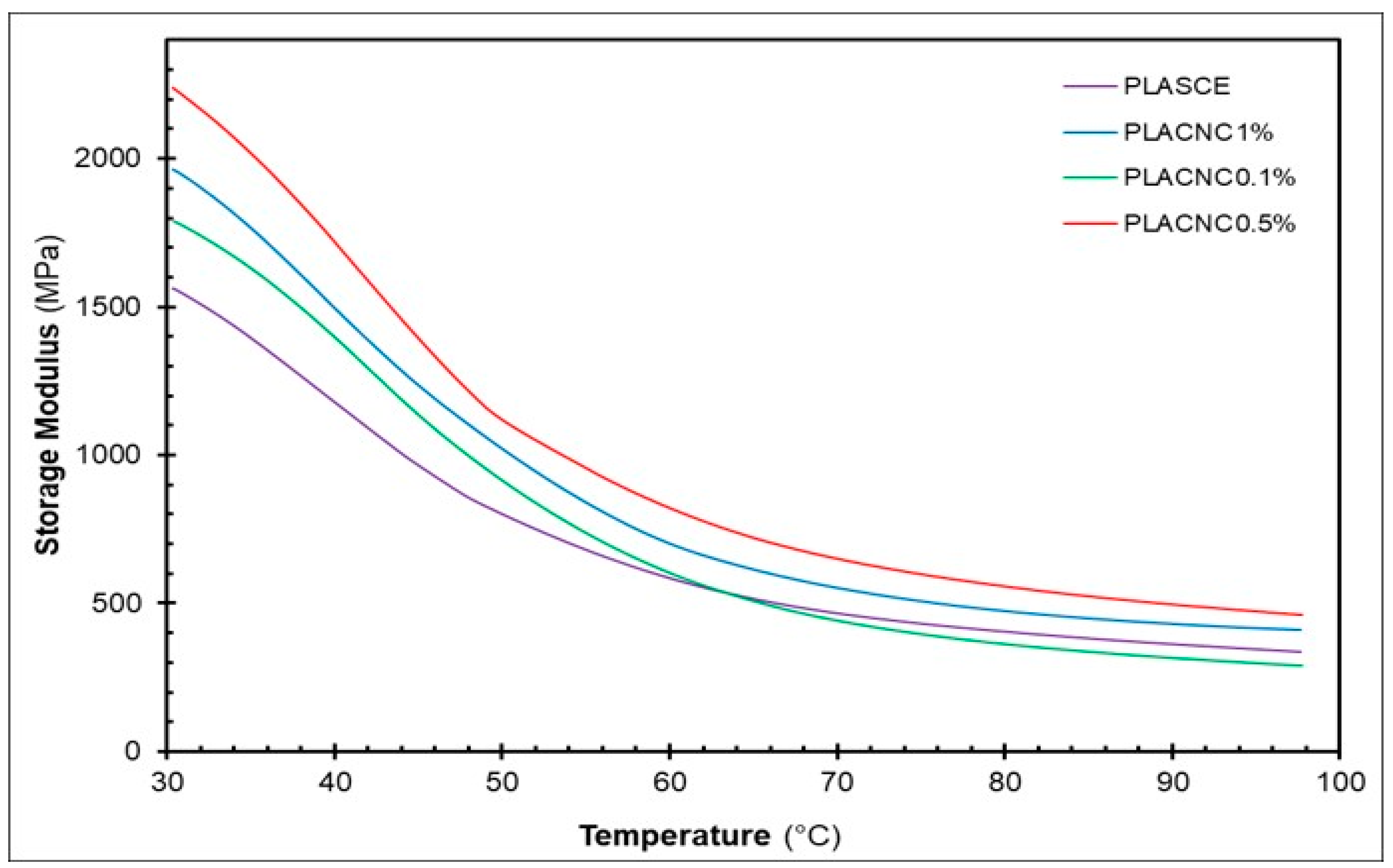
Dynamical mechanical analysis (DMA) was used to study the effect of temperature on the dynamic storage modulus (E’), loss modulus (E’’), and tangent delta (Tδ) of the 3D-printed specimens. The storage modulus (E’) expresses the relationship between energy stored (elastic) energy resulting from the applied strain and material stiffness. Figure 3 shows that the incorporation of cellulose nanocrystals (CNCs) resulted in a noticeable increase in the storage modulus (E’) of PLA/CNC bionanocomposites. The E’ recorded at 30 °C was 1559.99 MPa (PLASCE), 1786.83 MPa (PLACNC0.1%), 2241.59 MPa (PLACNC0.5%), and 1964.74 MPa (PLACNC1%), respectively. The 14.5%, 43.7%, and 25.9% increases in E’ indicate improved stress transfer between the cellulose nanocrystals (CNCs) and the PLA matrix [34,35]. Additionally, the increased material stiffness of the bionanocomposite specimen is also attributed to the presence of structurally stable PLA crystalline domains formed during the 10-min annealing step. The enhancement of PLA crystallization behaviour due to the nucleating effect of CNCs has been widely reported.
Furthermore, Figure 3 shows a progressive decrease in the storage modulus of all the bionanocomposites with increasing temperature. The absence of an inflection point on the E’ curves is attributed to the lubricating effect of the plasticizer, which enhanced the mobility of the PLA polymer chains at higher temperatures [36]. Nevertheless, the PLA/CNCs bionanocomposites containing 0.5% and 1% cellulose nanocrystals (CNCs) exhibited higher values of E’ throughout the temperature ramp regimen. However, the bionanocomposite containing 0.5% CNCs (PLACNC0.5%) exhibited the highest storage modulus; this observation is attributed to improved stiffness due to better CNC dispersion in the PLA matrix. Meanwhile, the slightly lower storage modulus observed for the 1% CNC specimen is attributed to aggregation and the inadequate dispersion of CNCs in the polymer matrix.
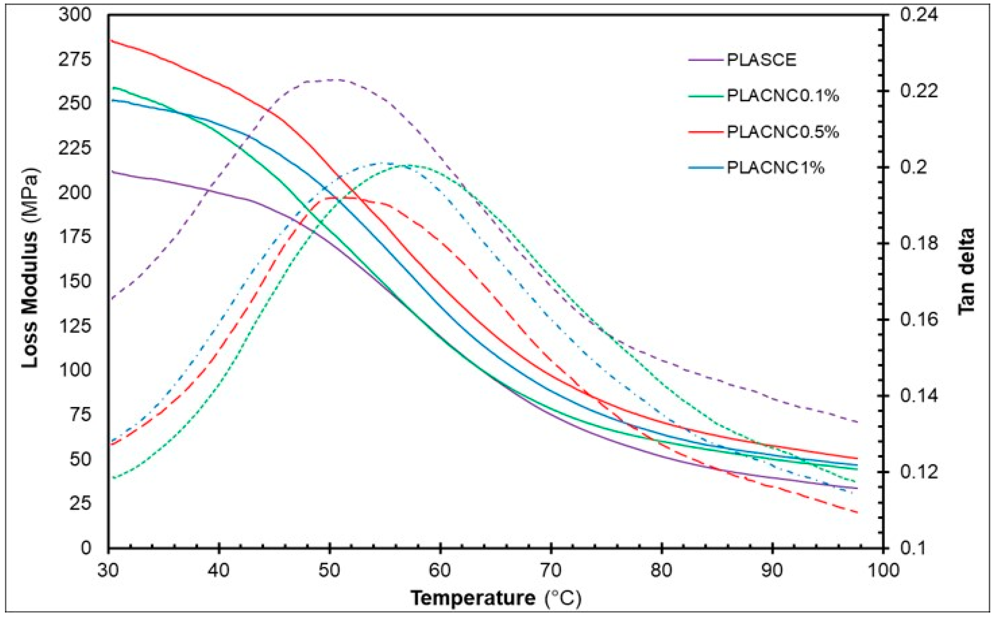
Figure 4 shows the energy dissipation (loss modulus: E”) and damping (tangent delta: tan δ) response of the materials to the temperature ramp and deformation strain. The maximum energy dissipation (loss modulus: E”) was recorded at 30 °C for all the samples. However, the incorporation of cellulose nanocrystals (CNCs) resulted in increased energy dissipation, as indicated by the loss modulus (E”) of PLA/CNC bionanocomposites. Similarly, the loss modulus (E”) progressively decreased with increasing temperature due to increased mobility of the PLA chains. The overlay plot of tangent delta (Tδ) versus temperature in Figure 4 shows the relationship between the dissipated (viscous) energy and stored (elastic) energy (E”/E’). The PLA/CNC bionanocomposites exhibited decreased Tδ curves compared to the specimen without CNCs. Moreover, the large area under the Tδ curves is indicative of improved damping properties associated with improved molecular mobility.
The reduction in Tδ is attributed to the restricted mobility of PLA chains due to the improved interaction with CNC particles [37]. However, the broadened Tδ peaks highlights the competing effect of plasticizer on the molecular chain mobility of the matrix. Maiza, M. et al. (2015) [38] attributed the broader transition peaks to the increased interactions between the hydroxyl groups of the PLA matrix and the plasticizer. Furthermore, the peak Tδ specifies the point where each material exhibited the highest viscous response to the applied deformation. The glass transition temperature (Tg) is defined as the temperature at the peak height of the tangent delta in Figure 4. The Tδ peak occurred at around 50 °C, 57 °C, 55 °C, and 56 °C for the PLASCE, PLACNC0.1%, PLACNC0.5%, and PLACNC1% specimens, respectively. The increase in the Tg values for PLA–CNCs is attributed to the decreased PLA chain mobility due to greater bonding between CNCs and PLAs. This is because the glass transition temperature (Tg) is associated with the energy dissipation potentials across the freely moving amorphous PLA chains [34,39].

3.2. Results of Deflection Temperature under Load (DTUL)

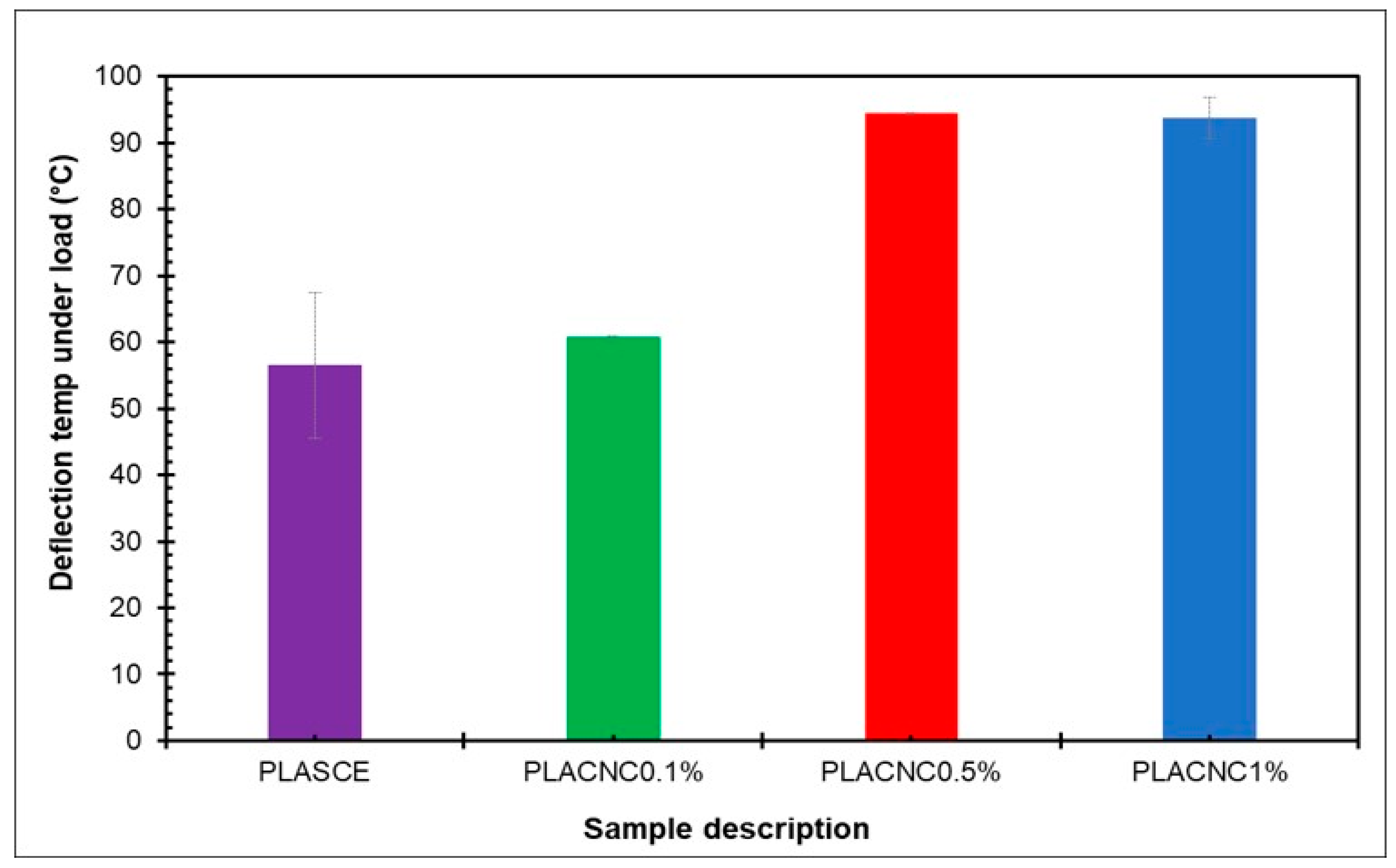
The DTUL or heat distortion temperature (HDT) indicates the maximum temperature at which each specimen may be used as a rigid material. Figure 5 shows the effect of cellulose nanocrystals (CNCs) on the DTUL of PLA bionanocomposites. The DTUL of the specimen without CNCs (PLASCE) was recorded at 56.47 ± 0.18 °C. However, a 4 °C increase was observed for the bionanocomposite specimen containing 0.1% CNCs (PLACNC0.1%~60.76 ± 0.10 °C). At higher loadings, a significant increase in the DTUL was observed for the bionanocomposite specimens containing 0.5% and 1% CNC, (PLACNC0.5%~94.41 ± 3.10 °C) and (PLACNC1% ~93.70 ± 6.08 °C).
Primarily, the improvement in mechanical properties can be attributed to the improved dispersion and reinforcing effects of CNC fibres present in the PLA matrix. Additionally, CNCs also favoured the formation of structurally and thermally stable crystalline PLA domains during the annealing process (10 min at 100 °C). The nucleating effect of CNC has been associated with the formation of more thermally stable crystalline domains in PLA [40]. Serizawa, S. et al. (2006) [41] reported an improved DTUL of PLA reinforced with kenaf fibre after annealing the composites for 4 h at 100 °C. Consequently, the combined contributions of improved crystallization and CNCs’ reinforcing effect are responsible for the significant improvement in the DTUL of PLA/CNC bionanocomposites.

3.3. Response to Static 3-Point Bending

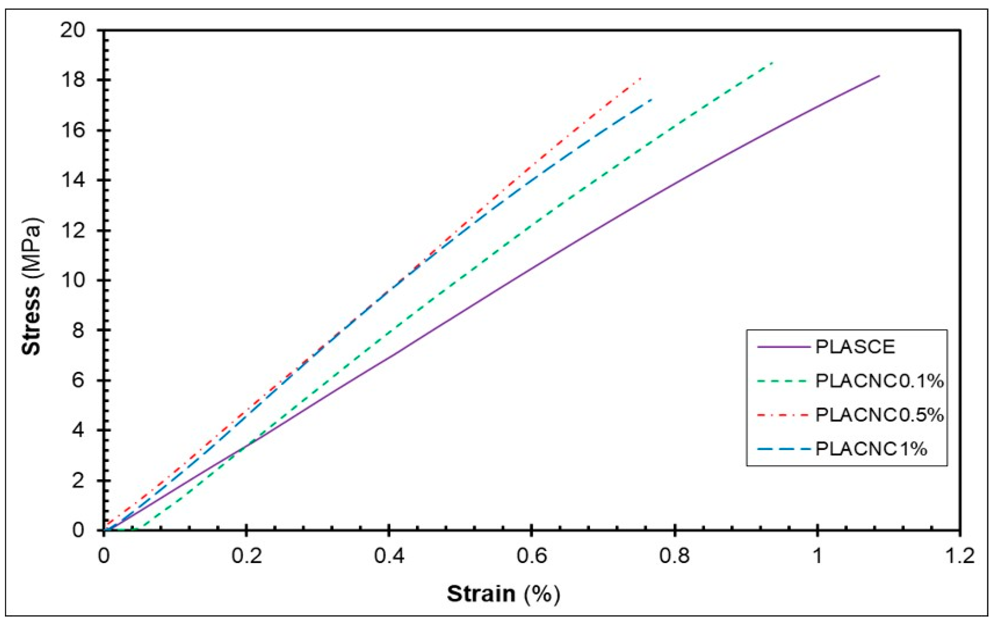
Figure 6 shows the stress–strain curves obtained from the static 3-point bending analysis. Table 2 shows the flexural modulus (E) and the flexural strain (εmax) at the maximum applied load (18N). All the samples analysed exhibited linear stress–strain curves. Table 2 shows a noticeable increase in the flexural modulus (E) for the PLA/CNC bionanocomposite specimens compared to PLASCE specimen. The 3D-printed specimens of PLACNC0.1% and PLACNC0.5% exhibited the highest (E) values of 1892.17 (±59.72) and 1871.16 (±54.06) MPa respectively, whereas the (E) of the 3D-printed PLACNC1% was slightly lower at 1674.18 (±186.73) MPa. The higher (E) is attributed to the reinforcing effect of CNCs on PLAs. However, the potential agglomeration of CNCs in PLACNC1% could have hindered the reinforcing efficiency.
Additionally, the nucleating effect of CNC could have resulted in the formation of more mechanically stable crystals in the PLA/CNC bionanocomposites attained during temperature conditioning at 100 °C. This increase in crystallinity explains the slightly lower flexural strain (ε max) observed for the PLA/CNC bionanocomposites (ε max = 0.99%). Comparatively, the PLASCE specimen was strained more easily (εmax = 1.42% ± 0.14) and showed lower flexural modulus (E = 1291.86 MPa ± 130.40). Again, the slopes of the stress–strain curves of the PLA/CNC bionanocomposites in Figure 6 are steeper than for PLASCE. This observation is also attributed to their improved strength and crystallinities. Dong, J. et al. (2019) [42] analysed the response behaviour of PLA-grafted cellulose nanofiber (PLA-g-CNF) composites under static 3-point bending and reported a similar observation. Their results revealed linear stress–strain curves for the annealed (heat-treated) specimens, whereas the unannealed specimens exhibited high flexural strain with concave-like stress–strain curves [42].

3.4. Creep and Recovery Behaviour

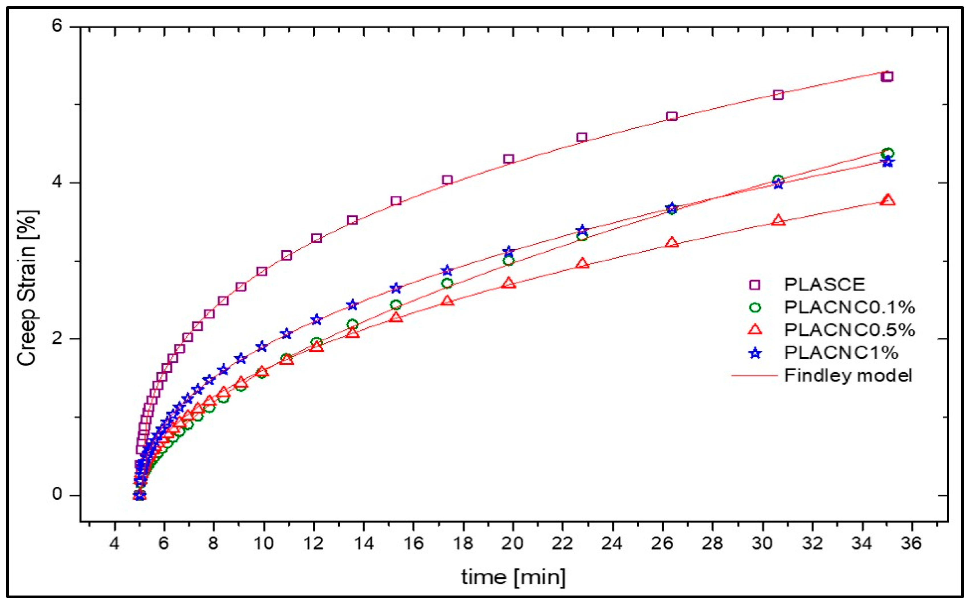
Figure 7 shows the comparison of the creep deformation phase recorded at 35 °C for the 3D-printed specimens of the plasticized PLA and PLA/CNC bionanocomposites. The creep strain–time [ε vs. (t)] curves reveal a characteristic transient (primary) and steady-state (secondary) creep behaviour [43]. Though all the specimens showed similar transient creep, the bionanocomposite specimens containing cellulose nanocrystals (CNC) exhibited lower secondary creep deformation. The resistance to creep deformation is indicative of higher material modulus, which agrees with the observation from the static 3-point bending results. For instance, the creep deformation at the 35th minute for PLACNC0.1%, PLACNC0.5%, and PLACNC1% was 18.3%, 29.66%, and 20.34% lower than that of the PLASCE specimen.
Furthermore, the empirical Findley’s power law model shown in Equation (2) was used to describe the viscoelastic creep response of the samples. This model has been successful to describe the creep behaviour of polymer composites containing natural fibres [43].
ε ( t ) = ε 0 + k t n  
where ε0 is the initial strain, t is the creep time, k is the coefficient of retardation, and the exponent n describes time dependence of the creep process [43,44]. Findley’s model was successfully fitted to the experimental data, as shown in Figure 7.
Table 3 shows the summary of the Findley model fitting parameters for the experimental creep data. The result reveals an inverse relationship between the values of the material constants k and n. The coefficient k for the bionanocomposite specimens containing CNCs was noticeably lower than that of the PLASCE specimen. Conversely, the numerical values of the coefficient n were higher for the bionanocomposite specimens. The higher coefficient n highlights the reduced segmental displacement of the PLA polymer chains during the duration of the creep deformation. Furthermore, the model showed a very good fitting with the experimental data, as indicated by the adjusted R2 values.
Figure 8 shows the creep recovery phase of the 3D-printed specimens of plasticized PLA and PLA/CNC bionanocomposite specimens after the 90-min period. The plot of the recovery strain vs. time (t) plots highlights the tendency of the specimens to return to their original form after the sustained deformation stress was removed. All the specimens exhibited rapid instantaneous elastic recovery during the first 10 min, afterwards followed by retarded elastic recovery. The observed non-linear recovery response arises from the dissipation of the energy stored within the specimen during the creep deformation phase [45]. Additionally, the permanent deformation after the 90-min recovery period was much lower than the total applied deformation. The plasticized PLA exhibited 95.04% creep recovery response, whereas the PLA/CNCs bionanocomposites exhibited 88.4%, 91.07% and 88.56% creep recovery at the end of 90 min. It is thus proposed that the slight reduction in recovery time is due to the increased matrix stiffness because of the incorporation of cellulose nanocrystals (CNCs).

3.5. Tensile Analysis of 3D Printed Bionanocomposites

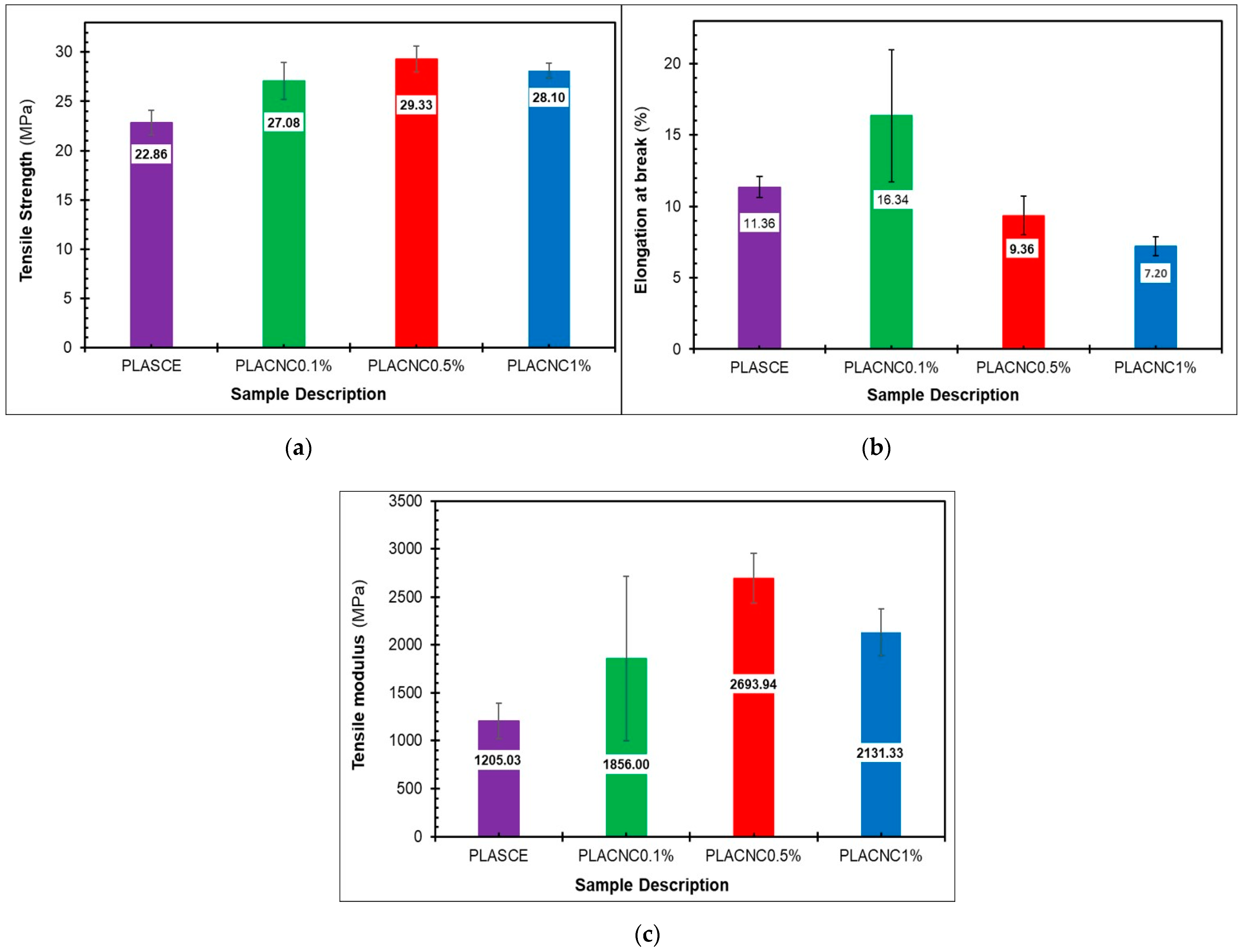
The tensile strength (σ), tensile modulus (E), and elongation at break (εb) of the 3D-printed specimens are reported in Table 4. The bionanocomposites containing 0.1%, 0.5%, and 1% cellulose nanocrystals exhibited slightly higher tensile strength (σ). Figure 9a shows the comparison between the tensile strength (σ) of PLASCE (22.86 ± 1.24 MPa), PLACNC0.1% (27.08 ± 1.87 MPa), PLACNC0.5%, (29.33 ± 1.32 MPa), and PLACNC1% (28.10 ± 0.75 MPa). Similarly, the tensile modulus (E) of the bionanocomposites increased significantly, as shown in Figure 9b. The increased modulus values are also in agreement with the results obtained from DMA static 3-point bending analysis. The bionanocomposite specimens containing 0.5% and 1% cellulose nanocrystals exhibited the highest stiffness, as indicated by the tensile modulus (E = 2693.94 ± 257.07 MPa and 2131.33 ±246.09 MPa). Meanwhile, the plasticized specimen exhibited the lowest tensile modulus (E = 1205.08 ± 185.80% MPa) due to reduced stiffness.
Figure 9c shows that the elongation at break (εb) of the plasticized specimen (PLASCE—11.36 ± 0.72%) was higher than those of the bionanocomposite specimens containing 0.5% and 1% cellulose nanocrystals (εb = 9.36 ± 1.36% and 7.20 ± 0.66%). The inverse relationship between tensile modulus (E) and elongation at break (εb) is attributed to the degree of PLA chain mobility under stress; higher PLA chain mobility results in increased elongation at break (εb) and reduced material stiffness (tensile modulus) [46]. However, a large deviation was recorded in the tensile modulus (E = 1856.00 ± 857.01 MPa) and elongation at break (εb = 16.34 ± 4.64) of the specimen containing 0.1% CNC. This deviation indicates a high variation in the tensile properties of the 3D-printed specimen containing 0.1% CNC.

3.6. Morphology of Tensile Fracture Surfaces

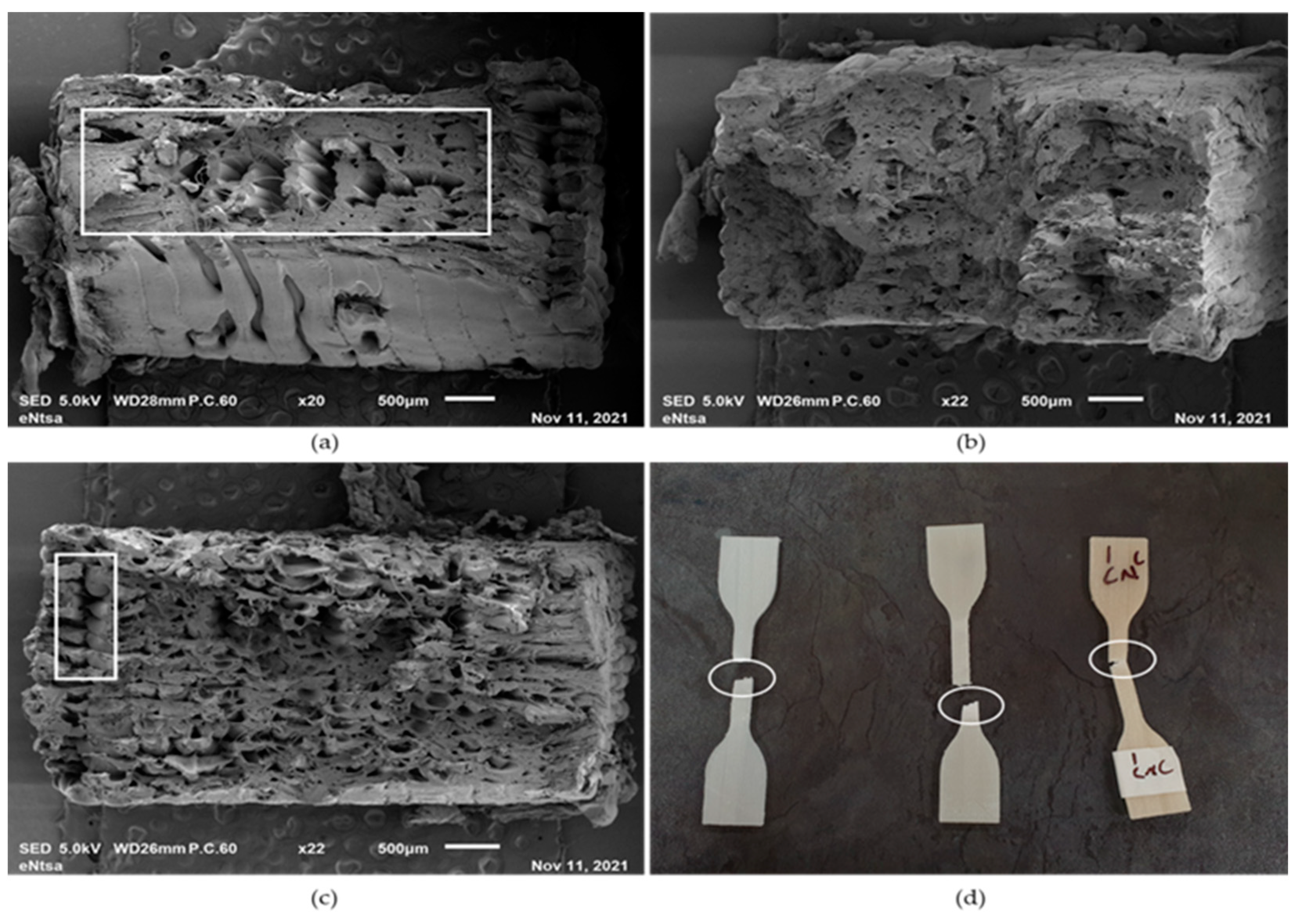
The fracture characteristics of the bionanocomposite specimens in Figure 10d reveal interlayer fracturing of the bionanocomposites; this is an excellent indication of good layer–layer adhesion. The whitening effect on the edges of the tensile specimen is attributed to strain crystallization and the crazing effect. The crazing of the amorphous domains is mainly influenced by the degree of crystallinity and spherulite size [47]. Figure 10a–c shows the tensile fracture surfaces of the PLA/CNC bionanocomposites recorded using scanning electron microscopy (SEM). The SEM micrographs revealed ductile fracture patterns, which agrees with the elongation at break (εb) values of the bionanocomposite specimens. The micrographs of all the bionanocomposite specimens revealed extensive porous microstructures with holes, voids, and layered structures, as highlighted in Figure 10a–c.
The porous microstructures negatively affected the mechanical properties of the 3D-printed specimens. The porous microstructure also explains the large deviation recorded in the tensile modulus (E) and elongation at break (εb) of the specimen containing 0.1% CNCs. The lack of layer adhesion seen in Figure 10a is attributed to the under-extrusion of materials during 3D printing. However, the SEM micrograph of the PLACNC0.5% specimen showed the least occurrence of voids and holes, which explains the higher mechanical properties recorded during tensile analysis. The anisotropy of the mechanical properties of 3D printed objects has been linked with inconsistent melt extrusion, poor interlayer bonding, and temperature fluctuations [48,49,50].

3.7. Effect of Wall Thickness on Shape Recovery Behaviour

Figure 11 shows the results for the effect of thickness on the shape recovery percentage (R%) of the 3D-printed cantilevers. The 1 mm cantilevers of PLASCE, PLACNC0.1%, PLACNC0.5%, and PLACNC1% bionanocomposites showed similar R% between 96.25–98.33%. However, a ~10% reduction in the shape recovery of the 2 mm cantilevers was recorded, as indicated by the lower R% values. The difference in the R% values of the 1 and 2 mm cantilevers is attributed to the inverse relationship between the rate of conduction heat transfer and sample thickness. Leist, S.K. et al. (2017) [21] reported similar observations after testing the shape recovery behaviour of 0.8 and 1.2 mm-thick PLA cantilevers.
The observed shape recovery behaviour emanates from the bulk mobility of the amorphous domain of the PLA polymer chains. The PLA matrix is a semi-crystalline thermoplastic composed of both amorphous and crystalline polymer chains. During the melt extrusion process of FDM 3D printing, the PLA polymer chains move freely. However, a permanent shape memory is imbued when the polymer chains get locked into a glassy state as the 3D printed part cools down. Similarly, the mobility in the amorphous region is restored by heating the cantilever above the glass transition temperature (Tg) of PLAs. This allows the cantilevers to be deformed and programmed (strained) into the desired temporary shapes. The temporary shape is maintained by cooling the samples below Tg to lock the amorphous chains in a glassy state. Consequently, the stored deformation strain energy is released when heat is resupplied, resulting in the observed shape recovery.

3.8. Demonstration Prototypes for 4D Applications

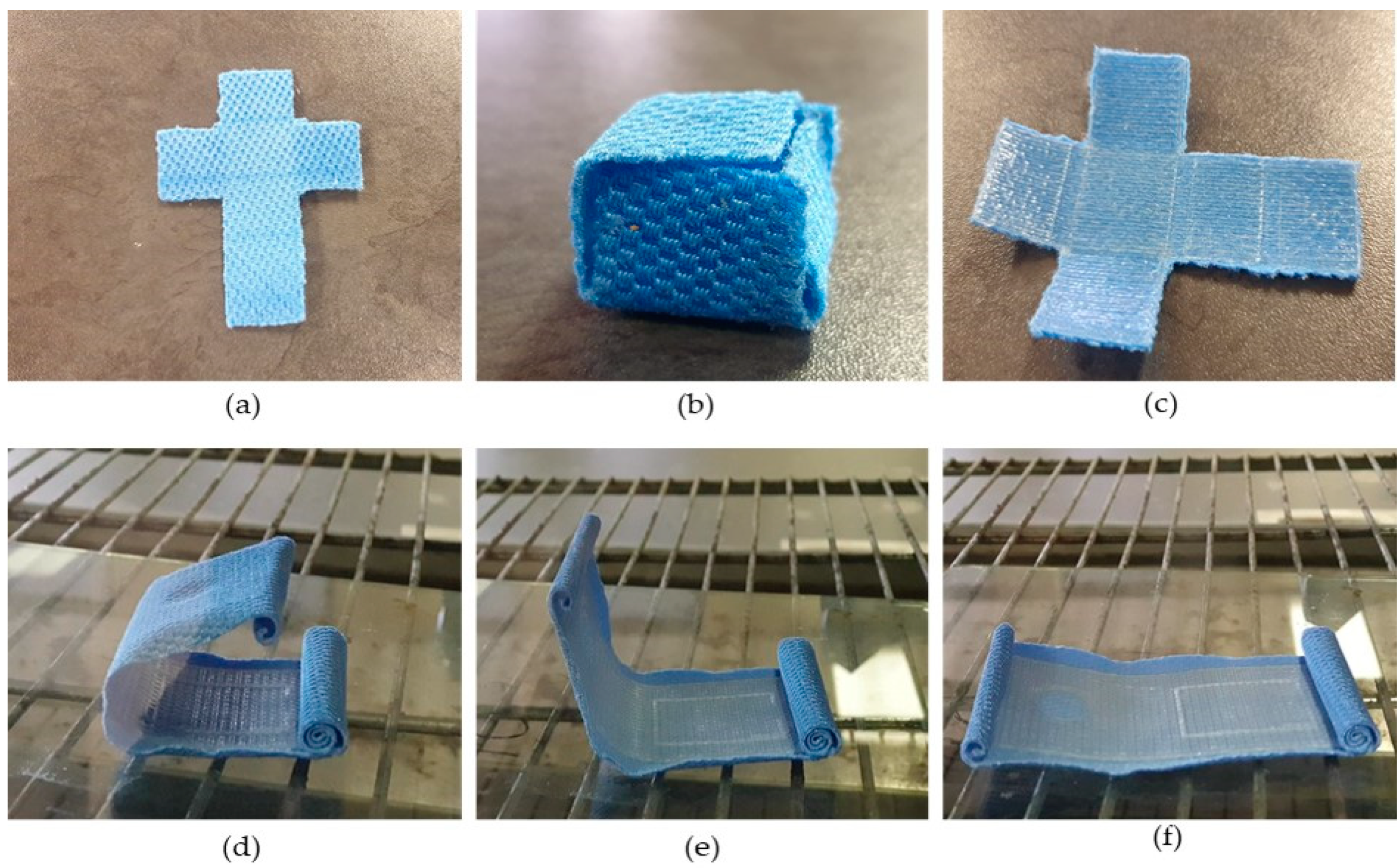
The 4D applicability of the PLA/CNC bionanocomposites was trialled by the direct 3D printing of two complex shapes onto textile fabrics. This resulted in a hybrid textile material with shape memory capabilities. The computer-aided design (CAD) model of the prototypes was designed using Autodesk® Tinkercad® software and saved as a stereolithography (STL) file. Afterwards, these shapes were directly 3D printed onto a knit nylon spandex fabric (Nylon 90%, Spandex 10%), as shown in Figure 12a. This fabric was chosen due to its strength to weight ratio, elasticity, and high melting point (~259 °C). Heat resistance is key to ensure the fabric remains thermally stable during direct 3D printing. The nylon spandex fabric was attached onto the print bed using a double-sided tape. The printing temperature was set at 190 °C with the bed temperature at 50 °C. To ensure proper adhesion, nozzle height and bed levelling were adjusted prior to printing. The printing speed was lowered to 30 mm/sec to prevent crimping of the nylon fabric. The shape recovery behaviour of the demonstrative prototypes was also investigated using the steps highlighted earlier. The first prototype (P1) features a foldable cross-pattern, as shown in Figure 12b. The cross-pattern design can be subdivided into six distinct square shapes, joined together by four narrow rectangular internal splines (narrow grooves). The four splines were distinctly positioned in the four folding points where the cross-pattern would be folded into the 4D cube shape. The second prototype (P2) design features a 3D-printed bionanocomposite grid pattern with clearly outlined sections, as seen in Figure 12c.
Furthermore, Figure 13a–c shows the cross-pattern prototype (P1) before and after the shape recovery process. Likewise, the shape recovery capabilities of the grid-patterned prototype are shown in Figure 13d–f. Shape memory and shape recovery behaviours can be very useful in 4D printing applications. This attribute allows for the development of shape memory objects via 3D printing, followed by a further transformation into a temporary 4D shape. Afterwards, the 4D object can be transformed back into the original shape upon the application of the right stimulus. In both instances shown in Figure 13b,e, heat was applied as a stimulus to trigger the shape recovery process.
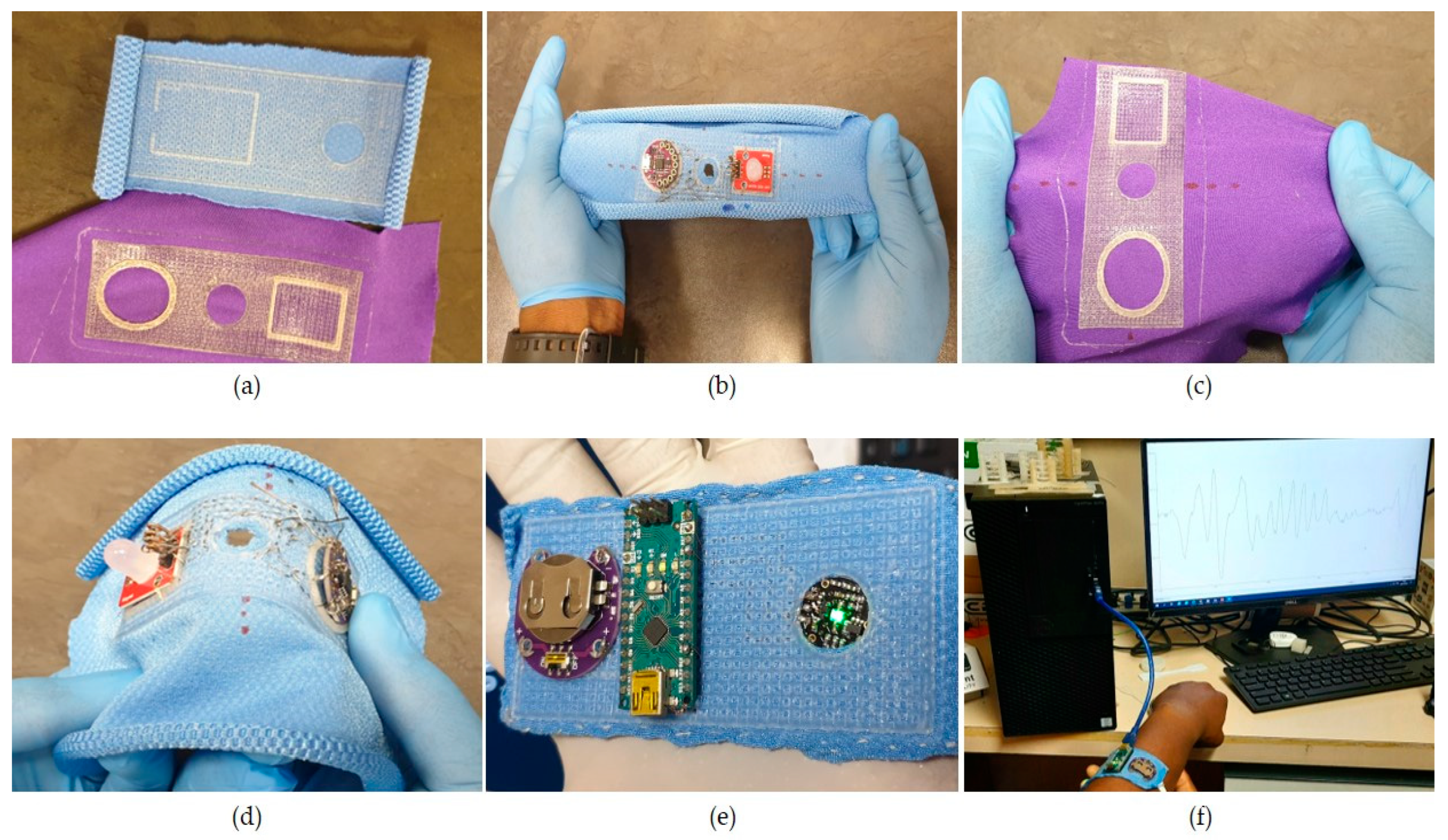
Furthermore, a close visual and haptic inspection revealed excellent adhesion between the PLA/CNC bionanocomposite and the nylon spandex fabric. This indicates good compatibility between the two materials. The adhesion was further tested by subjecting the prototype (P2) material to stretching and bending deformations, as shown in Figure 14a–d. The grid functioned as a lightweight exoskeleton on the nylon spandex fabric. Ultimately, the hybrid prototype (P2) material exhibited an excellent balance between strength and flexibility, thus making it a potentially good candidate for application in smart, wearable textile materials. This idea was further experimented by attaching wearable electronics onto prototype (P2) to transform it into a e-textile device (Figure 14b,d,e). The e-textile device featured a heart (pulse) rate sensor, LED lights, and a programmable Wi-Fi-enabled microcontroller (Arduino nano). The conductive pathway was established using enamel-coated copper wires. The entire circuitry was directly handstitched, and the contact points were soldered to establish a connection. The pulse monitoring capabilities of the e-textile device were tested out, as shown in Figure 14f.

4. Summary and Conclusions

This study demonstrated the application of cellulose nanocrystal (CNC)-reinforced polylactic acid (PLA) bionanocomposites in the 3D printing of dynamic 4D objects with tailored functionalities. The PLA/CNC bionanocomposite filaments were successfully 3D printed using a fused deposition modelling (FDM) 3D printer. The investigation conducted on the flexural and mechanical analysis of the FDM 3D-printed specimens revealed improvements in the mechanical properties of the bionanocomposites. The superior mechanical and crystallization behaviour of the PLA/CNC bionanocomposites resulted in a superior deflection temperature under load (DTUL). Furthermore, tensile and static 3-point bending analyses also confirmed improvements in tensile strength, modulus, and the elongation at break of the 3D-printed bionanocomposite specimens. This was attributed to the reinforcing and nucleating effects of the CNCs. The bionanocomposite specimens exhibited excellent shape memory and shape recovery behaviours. Finally, the balance between the strength and flexibility of the bionanocomposites resulted in a successful demonstration of the potential 4D applications.

Author Contributions

Conceptualization, V.C.A. and M.J.J.; methodology, V.C.A.; 3D printing, V.C.A.; formal analysis, V.C.A. and P.H.; investigation, V.C.A.; resources, M.J.J., P.H., and J.A.; data curation, V.C.A.; writing—original draft preparation, V.C.A., P.H., and M.J.J.; writing—review and editing, V.C.A., P.H., and M.J.J.; visualization, V.C.A.; supervision, M.J.J. and P.H.; project administration, M.J.J. and P.H.; funding acquisition, M.J.J. All authors have read and agreed to the published version of the manuscript.

Funding

This research was funded by Department of Science and Innovation (DSI), South Africa—Biorefinery Consortium Project—under the DSI Bioeconomy program, Grant number DST/CON0188/2017.

Institutional Review Board Statement

Not applicable.

Informed Consent Statement

Not applicable.

Data Availability Statement

The data presented in this study are available on request from the corresponding author.

Acknowledgments

Funding from Department of Science and Innovation (DSI), South Africa—Biorefinery Consortium Project—under the DSI Bioeconomy program is gratefully acknowledged by the authors. The centre for rubber science and technology (CRST), Nelson Mandela University, South Africa is duly acknowledged for instrumentation and testing equipment’s.

Conflicts of Interest

The authors declare no conflict of interest.

References

  1. Behl, M.; Razzaq, M.Y.; Lendlein, A. Multifunctional shape-memory polymers. Adv. Mater. 2010, 22, 3388–3410. [Google Scholar] [CrossRef] [PubMed]
  2. Kunzelman, J.; Chung, T.; Mather, P.T.; Weder, C. Shape memory polymers with built-in threshold temperature sensors. J. Mater. Chem. 2008, 18, 1082–1086. [Google Scholar] [CrossRef]
  3. El Feninat, F.; Laroche, G.; Fiset, M.; Mantovani, D. Shape memory materials for biomedical applications. Adv. Eng. Mater. 2002, 4, 91–104. [Google Scholar] [CrossRef]
  4. Rossiter, J.; Walters, P.; Stoimenov, B. Printing 3D dielectric elastomer actuators for soft robotics. Electroact. Polym. Actuator Devices 2009, 7287, 149–158. [Google Scholar]
  5. Ge, Q.; Westbrook, K.K.; Mather, P.T.; Dunn, M.L.; Qi, H.J. Thermomechanical behavior of a two-way shape memory composite actuator. Smart Mater. Struct. 2013, 22, 055009. [Google Scholar]
  6. Liu, Y.; Gall, K.; Dunn, M.L.; McCluskey, P. Thermomechanics of shape memory polymer nanocomposites. Mech. Mater. 2004, 36, 929–940. [Google Scholar] [CrossRef]
  7. Sharma, N.; Raj, T.; Jangra, K. Applications of nickel-titanium alloy. J. Eng. Technol. 2015, 5, 1. [Google Scholar] [CrossRef]
  8. Meier, H.; Haberland, C.; Frenzel, J.; Zarnetta, R. Selective Laser Melting of NiTi Shape Memory Components. In Innovative Developments in Design and Manufacturing; CRC Press: Boca Raton, FL, USA, 2009; pp. 251–256. [Google Scholar]
  9. Huang, W.; Yang, B.; An, L.; Li, C.; Chan, Y. Water-driven programmable polyurethane shape memory polymer: Demonstration and mechanism. Appl. Phys. Lett. 2005, 6, 114105. [Google Scholar] [CrossRef]
  10. Du, H.; Zhang, J. Solvent induced shape recovery of shape memory polymer based on chemically cross-linked poly (vinyl alcohol). Soft Matter 2010, 6, 3370–3376. [Google Scholar] [CrossRef]
  11. Wang, X.; Lu, H.; Shi, X.; Yu, K.; Fu, Y.Q. A thermomechanical model of multi-shape memory effect for amorphous polymer with tunable segment compositions. Compos. Part B Eng. 2019, 160, 298–305. [Google Scholar] [CrossRef]
  12. Leng, J.; Lan, X.; Liu, Y.; Du, S. Shape-memory polymers and their composites: Stimulus methods and applications. Progress Mater. Sci. 2011, 56, 1077–1135. [Google Scholar] [CrossRef]
  13. Barbier, M.; Le Guen, M.J.; McDonald-Wharry, J.; Bridson, J.H.; Pickering, K.L. Quantifying the Shape Memory Performance of a Three-Dimensional-Printed Biobased Polyester/Cellulose Composite Material. 3D Print. Addit. Manuf. 2021, 8, 193–200. [Google Scholar] [CrossRef]
  14. Behl, M.; Lendlein, A. Actively moving polymers. Soft Matter 2007, 3, 58–67. [Google Scholar] [CrossRef]
  15. Monzón, M.; Paz, R.; Pei, E.; Ortega, F.; Suárez, L.; Ortega, Z.; Alemán, M.E.; Plucinski, T.; Clow, N. 4D printing: Processability and measurement of recovery force in shape memory polymers. Intern. J. Adv. Manuf. Technol. 2017, 89, 1827–1836. [Google Scholar] [CrossRef] [Green Version]
  16. Wu, T.; Frydrych, M.; O’Kelly, K.; Chen, B. Poly (glycerol sebacate urethane)-cellulose nanocomposites with water-active shape-memory effects. Biomacromolecules 2014, 15, 2663–2671. [Google Scholar] [CrossRef] [PubMed]
  17. Jing, X.; Mi, H.-Y.; Huang, H.-X.; Turng, L.-S. Shape memory thermoplastic polyurethane (TPU)/poly (ε-caprolactone)(PCL) blends as self-knotting sutures. J. Mech. Behav. Biomed. Mater. 2016, 64, 94–103. [Google Scholar] [CrossRef] [PubMed]
  18. Baker, R.M.; Tseng, L.-F.; Iannolo, M.T.; Oest, M.E.; Henderson, J.H. Self-deploying shape memory polymer scaffolds for grafting and stabilizing complex bone defects: A mouse femoral segmental defect study. Biomaterial 2016, 76, 388–398. [Google Scholar] [CrossRef] [PubMed]
  19. Senatov, F.; Zadorozhnyy, M.Y.; Niaza, K.; Medvedev, V.; Kaloshkin, S.; Anisimova, N.Y.; Kiselevskiy, M.V.; Yang, K.-C. Shape memory effect in 3D-printed scaffolds for self-fitting implants. Eur. Polym. J. 2017, 93, 222–231. [Google Scholar] [CrossRef]
  20. Senatov, F.S.; Niaza, K.V.; Zadorozhnyy, M.Y.; Maksimkin, A.; Kaloshkin, S.; Estrin, Y. Mechanical properties and shape memory effect of 3D-printed PLA-based porous scaffolds. J. Mech. Behav. Biomed. Mater. 2016, 57, 139–148. [Google Scholar] [CrossRef]
  21. Leist, S.K.; Gao, D.; Chiou, R.; Zhou, J. Investigating the shape memory properties of 4D printed polylactic acid (PLA) and the concept of 4D printing onto nylon fabrics for the creation of smart textiles. Virtual Phys. Prototype. 2017, 12, 290–300. [Google Scholar] [CrossRef]
  22. Ganguly, S.; Das, P. Synthesis and Production of Polylactic Acid (PLA). In Polylactic Acid-Based Nanocellulose and Cellulose Composites; CRC Press: Boca Raton, FL, USA, 2022; pp. 29–50. [Google Scholar]
  23. Wei, Z.; Sandstroröm, R.; Miyazaki, S. Shape-memory materials and hybrid composites for smart systems: Part I Shape-memory materials. J. Mater. Sci. 1998, 33, 3743–3762. [Google Scholar] [CrossRef]
  24. Grijpma, D.; Penning, J.; Pennings, A. Chain entanglement, mechanical properties and drawability of poly (lactide). Colloid Polym. Sci. 1994, 272, 1068–1081. [Google Scholar] [CrossRef]
  25. Sun, Y.-C.; Wan, Y.; Nam, R.; Chu, M.; Naguib, H.E. 4D-printed hybrids with localized shape memory behaviour: Implementation in a functionally graded structure. Sci. Rep. 2019, 9, 18754. [Google Scholar] [CrossRef] [PubMed] [Green Version]
  26. Barmouz, M.; Behravesh, A.H. Shape memory behaviors in cylindrical shell PLA/TPU-cellulose nanofiber bio-nanocomposites: Analytical and experimental assessment. Compos. Part A Appl. Sci. Manuf. 2017, 101, 160–172. [Google Scholar] [CrossRef]
  27. Navarro-Baena, I.; Sessini, V.; Dominici, F.; Torre, L.; Kenny, J.M.; Peponi, L. Design of biodegradable blends based on PLA and PCL: From morphological, thermal and mechanical studies to shape memory behavior. Polym. Degrad. Stab. 2016, 132, 97–108. [Google Scholar] [CrossRef]
  28. John, M.J.; Dyanti, N.; Mokhena, T.; Agbakoba, V.; Sithole, B. Design and development of cellulosic bionanocomposites from forestry waste residues for 3d printing applications. Material 2021, 14, 3462. [Google Scholar] [CrossRef]
  29. Cao, L.; Liu, C.; Zou, D.; Zhang, S.; Chen, Y. Using cellulose nanocrystals as sustainable additive to enhance mechanical and shape memory properties of PLA/ENR thermoplastic vulcanizates. Carbohydr. Polym. 2020, 230, 115618. [Google Scholar] [CrossRef]
  30. Saralegi, A.; Gonzalez, M.L.; Valea, A.; Eceiza, A.; Corcuera, M.A. The role of cellulose nanocrystals in the improvement of the shape-memory properties of castor oil-based segmented thermoplastic polyurethanes. Compos. Sci. Technol. 2014, 92, 27–33. [Google Scholar] [CrossRef]
  31. Hassouna, F.; Raquez, J.-M.; Addiego, F.; Dubois, P.; Toniazzo, V.; Ruch, D. New approach on the development of plasticized polylactide (PLA): Grafting of poly (ethylene glycol)(PEG) via reactive extrusion. Eur. Polym. J. 2011, 47, 2134–2144. [Google Scholar] [CrossRef]
  32. Jandyal, A.; Chaturvedi, I.; Wazir, I.; Raina, A.; Haq, M.I.U. 3D printing—A review of processes, materials and applications in industry 4.0. Sustain. Op. Compos. 2022, 3, 33–42. [Google Scholar] [CrossRef]
  33. Yang, Z.; Jia, S.; Niu, Y.; Lv, X.; Fu, H.; Zhang, Y.; Liu, D.; Wang, B.; Li, Q. Bean-Pod-Inspired 3D-Printed Phase Change Microlattices for Solar-Thermal Energy Harvesting and Storage. Small 2021, 17, 2101093. [Google Scholar] [CrossRef] [PubMed]
  34. Huda, M.; Drzal, L.; Mohanty, A.; Misra, M. The effect of silane treated-and untreated-talc on the mechanical and physico-mechanical properties of poly (lactic acid)/newspaper fibers/talc hybrid composites. Compos. Part B Eng. 2007, 38, 367–379. [Google Scholar] [CrossRef]
  35. Hedenberg, P.; Gatenholm, P. Conversion of plastic/cellulose waste into composites. I. Model of the interphase. J. Appl. Polym. Sci. 1995, 56, 641–651. [Google Scholar] [CrossRef]
  36. Hassouna, F.; Raquez, J.-M.; Addiego, F.; Toniazzo, V.; Dubois, P.; Ruch, D. New development on plasticized poly (lactide): Chemical grafting of citrate on PLA by reactive extrusion. Eur. Polym. J. 2012, 48, 404–415. [Google Scholar] [CrossRef]
  37. Yong, A.X.; Sims, G.D.; Gnaniah, S.J.; Ogin, S.L.; Smith, P.A. Heating rate effects on thermal analysis measurement of T g in composite materials. Adv. Manuf. Polym. Compos. Sci. 2017, 3, 43–51. [Google Scholar] [CrossRef] [Green Version]
  38. Maiza, M.; Benaniba, M.T.; Quintard, G.; Massardier-Nageotte, V. Biobased additive plasticizing Polylactic acid (PLA). Polimer. 2015, 25, 581–590. [Google Scholar] [CrossRef]
  39. Wunderlich, B. Thermal Analysis; Academic Press: San Diego, CA, USA, 1990; pp. 171–180. [Google Scholar]
  40. Li, H.; Cao, Z.; Wu, D.; Tao, G.; Zhong, W.; Zhu, H.; Qiu, P.; Liu, C. Crystallisation, mechanical properties and rheological behaviour of PLA composites reinforced by surface modified microcrystalline cellulose. Plast. Rubber Compos. 2016, 45, 181–187. [Google Scholar] [CrossRef]
  41. Serizawa, S.; Inoue, K.; Iji, M. Kenaf-fiber-reinforced poly (lactic acid) used for electronic products. J. Appl. Polym. Sci. 2006, 100, 618–624. [Google Scholar] [CrossRef]
  42. Dong, J.; Mei, C.; Han, J.; Lee, S.; Wu, Q. 3D printed poly (lactic acid) composites with grafted cellulose nanofibers: Effect of nanofiber and post-fabrication annealing treatment on composite flexural properties. Addit. Manuf. 2019, 28, 621–628. [Google Scholar] [CrossRef]
  43. Zhao, L.; Wei, Y.; Zhang, G.W.; Xi, F. Short-term creep properties and creep model of wood-plastic composites. Polym. Compos. 2022, 43, 924–933. [Google Scholar] [CrossRef]
  44. Dul, S.; Fambri, L.; Pegoretti, A. Filaments production and fused deposition modelling of ABS/carbon nanotubes composites. Nanomaterial 2018, 8, 49. [Google Scholar] [CrossRef] [PubMed] [Green Version]
  45. Steffe, J.F. Rheological Methods in Food Process Engineering; Freeman press: Valleyford, WA, USA, 1996. [Google Scholar]
  46. Mathew, A.P.; Oksman, K.; Sain, M. Mechanical properties of biodegradable composites from poly lactic acid (PLA) and microcrystalline cellulose (MCC). J. Appl. Polym. Sci. 2005, 97, 2014–2025. [Google Scholar] [CrossRef]
  47. Herrera, N.; Mathew, A.P.; Oksman, K. Plasticized polylactic acid/cellulose nanocomposites prepared using melt-extrusion and liquid feeding: Mechanical, thermal and optical properties. Compos. Sci. Technol. 2015, 106, 149–155. [Google Scholar] [CrossRef]
  48. Dizon, J.R.C.; Espera, A.H., Jr.; Chen, Q.; Advincula, R.C. Mechanical characterization of 3D-printed polymers. Addit. Manuf. 2018, 20, 44–67. [Google Scholar] [CrossRef]
  49. Song, Y.; Li, Y.; Song, W.; Yee, K.; Lee, K.-Y.; Tagarielli, V.L. Measurements of the mechanical response of unidirectional 3D-printed PLA. Mater. Des. 2017, 123, 154–164. [Google Scholar] [CrossRef]
  50. Chacón, J.; Caminero, M.A.; García-Plaza, E.; Núnez, P.J. Additive manufacturing of PLA structures using fused deposition modelling: Effect of process parameters on mechanical properties and their optimal selection. Mater. Des. 2017, 124, 143–157. [Google Scholar] [CrossRef]
Figure 1. Sketches of tensile, DMA and shape memory analysis specimens; lines indicating the raster angles.
Sustainability 14 12759 g001
Figure 2. Determination of shape recovery behaviour: (a) starting shape; (b) temporary shape; (c) shape recovery.
Sustainability 14 12759 g002
Figure 3. Plots showing the temperature dependency of the storage modulus of 3D-printed PLASCE, PLACNC0.1%, PLACNC0.5%, and PLACNC1% specimens.
Sustainability 14 12759 g003
Figure 4. Plots showing the temperature dependency of loss modulus (solid lines) and tan delta (dashed lines) of 3D-printed PLASCE, PLACNC0.1%, PLACNC0.5%, and PLACNC1% specimens.
Sustainability 14 12759 g004
Figure 5. Comparison of deflection temperature under load of 3D printed PLASCE, PLACNC0.1%, PLACNC0.5%, and PLACNC1% specimens.
Sustainability 14 12759 g005
Figure 6. Static 3-point bending stress–strain curves of 3D-printed PLASCE, PLACNC0.1%, PLACNC0.5%, and PLACNC1% specimens (at 30 °C).
Sustainability 14 12759 g006
Figure 7. Creep deformation curves of 3D-printed PLASCE, PLACNC0.1%, PLACNC0.5%, and PLACNC1% specimens (at 35 °C): Findley model (red solid line).
Sustainability 14 12759 g007
Figure 8. Creep recovery curves of 3D-printed PLASCE, PLACNC0.1%, PLACNC0.5%, and PLACNC1% specimens (at 35 °C).
Sustainability 14 12759 g008
Figure 9. Bar graph showing; tensile strength σ (a), tensile modulus E (b), and elongation at break εb (c) of the 3D-printed PLASCE, PLACNC0.1%, PLACNC0.5%, and PLACNC1% specimens.
Sustainability 14 12759 g009
Figure 10. Morphology of tensile fracture surfaces of 3D-printed specimens: (a) PLACNC0.1%, (b) PLACNC0.5%, and (c) PLACNC1% specimens, and (d) shows the interlayer fractures of the tensile specimens.
Sustainability 14 12759 g010
Figure 11. Comparison of% shape recovery of 1 mm and 2 mm 3D-printed cantilevers of PLASCE, PLACNC0.1%, PLACNC0.5%, and PLACNC1% (at 65 °C).
Sustainability 14 12759 g011
Figure 12. (a) Direct 3D printing of PLA/CNC bionanocomposites onto nylon spandex fabric; (b) Schematic design of prototype P1; (c) Schematic design of prototype P2.
Sustainability 14 12759 g012
Figure 13. PLA/CNC bionanocomposite prototypes showing the material behaviour before, during, and after heat-activated shape memory response: (ac) cross-patterned prototype P1; (df) grid-patterned prototype P2.
Sustainability 14 12759 g013
Figure 14. Images of PLA/CNC bionanocomposites directly 3D printed on nylon fabrics; (ad) Visual and haptic inspection, (e) attached wearable electronics, (f) heart rate measurement using e-textile device.
Sustainability 14 12759 g014
Table 1. Filament description.
Sample DescriptionFilament Diameter (mm)CNC c Content (wt.%)Tensile Strength (MPa)Elongation at Break (%)Melting Temp (°C)Glass Transition Temp (°C)
PLASCE a1.66 (±0.05)028.9 (±1.52)15.8 (±4.34)166.4356.72
PLACNC0.1%b1.68 (±0.05)0.135.3 (±1.79)15.4 (±4.31)164.1656.29
PLACNC0.5%b1.67 (±0.06)0.533.4 (±2.07)13.1 (±4.61)163.5954.48
PLACNC1%b1.74(±0.04)135.1 (±4.07)25.5 (±5.38)165.3049.22
a PLA containing plasticizer and chain extender. b PLA containing plasticizer, chain extender and cellulose nanocrystals. c Cellulose nanocrystals (CNC).
Table 2. Flexural modulus (E) and flexural strain (εmax) at the maximum applied load (18N).
Static Bending Force (at 30° C)
Sample DescriptionFlexural Modulus, E (MPa)Flexural Strain εmax (%)
PLASCE1291.86 (±130.40)1.42 (±0.14)
PLACNC0.1%1892.17 (±59.72)0.99 (±0.03)
PLACNC0.5%1871.16 (±54.06)0.97 (±0.03)
PLACNC1%1674.18 (±186.73)0.99 (±0.19)
Table 3. Findley’s law fitting parameters of the creep deformation.
Sample DescriptionFindley Model Parameters
knR2
PLASCE1.76890.33870.9995
PLACNC0.1%0.61190.57850.9994
PLACNC0.5%0.71850.48380.9994
PLACNC1%0.96170.44240.9999
Table 4. Tensile analysis results of 3D-printed bionanocomposite specimens.
Sample DescriptionCNC a Content (wt.%)Tensile Strength (MPa)Tensile Modulus (MPa)Elongation at Break (%)
PLASCE022.86 ±1.241205.08 ±185.8011.36 ±0.72
PLACNC0.1%0.127.08 ±1.871856.00 ±857.0116.34 ±4.64
PLACNC0.5%0.529.33 ±1.322693.94 ±257.079.36 ±1.36
PLACNC1%128.10 ±0.752131.33 ±246.097.20 ±0.66
a Cellulose nanocrystals.
Publisher’s Note: MDPI stays neutral with regard to jurisdictional claims in published maps and institutional affiliations.