Article

Instant Closing of Permanent Magnet Synchronous Motor Control Systems at Open-Loop Start

Daeyoung R&D Center, Yongin 16954, Korea
Sustainability 2022, 14(19), 12665; https://doi.org/10.3390/su141912665
Submission received: 13 September 2022 / Revised: 27 September 2022 / Accepted: 30 September 2022 / Published: 5 October 2022

Abstract

:
Nowadays, position sensorless permanent magnet synchronous motor drives are gaining popularity quite rapidly, and have become almost standard in many applications such as compressors, high speed pumps, etc. All of these drives involve estimators to calculate the speed and the position of the rotor, which are necessary for proper operation of vector control. While these estimators, with the exception of injection-based ones, work well in the middle and high-speed ranges, they cannot operate at low speeds. In order to overcome this problem, sensorless control systems include different starting techniques, with the most popular being open-loop starting. In this approach, the motor is accelerated in open-loop mode until it reaches the speed where estimator operates stably, then the control system is closed. However, the weakest point of this method is the technology of closing the system, which typically creates transients and can even be the cause of loss of stability. This paper proposes a method for instant and seamless transition from open-loop to closed loop which works perfectly under different load conditions. Other starting techniques are considered and compared with the proposed method.

1. Introduction

Permanent magnet synchronous machines (PMSM) have higher efficiency, torque to weight, and power to volume ratios compared to machines of other types [1,2], which makes them attractive for solutions which prioritize efficiency and compactness [3], are used inside autonomous objects [4], or focus green energy and decreased CO2 emissions [5,6,7]. As a result, PMSM drives have become an attractive object for researchers, and a large number of studies dedicated to different aspects of PMSM design and control have been published. At the same time, certain control problems have not wholly been studied, and provide opportunities for optimization and improvements. One of these tasks, which is considered in the current manuscript, is the closing of sensorless control systems after motor open-loop starting.
The most popular PMSM control technique is a vector control, which fully utilizes the motor’s potential and provides higher efficiency. As this type of control requires information on rotor position and speed motor drives are typically equipped with position encoders, which can provide such information. At the same time, encoders increase the total cost of developing motor drives and decrease their reliability. Therefore, they are undesirable in low-cost applications (home appliances, etc.) or motor drives with hard access to the motor for maintenance (compressors, etc.). In order to eliminate position sensors, various sensorless techniques providing information on speed and position have been proposed and successfully implemented. Furthermore, sensorless solutions have almost become standard in many areas, such as compressing and pumping applications [8].
Generally, sensorless techniques for PM motors can be divided into two groups, injection-based [9] and rotor field detection-based [10]. The methods of the first group use magnetic anisotropy of the rotor, which is present in more or less all types of PM machines. In order to define the rotor’s position, these algorithms inject high-frequency signals of a predefined type and analyze the response to this injection. The main advantage of these techniques is the ability to operate at zero speed; however, their application is strongly limited by several drawbacks. Because these techniques use motor magnetic asymmetry along direct and quadrature axes, they work better with interior type PMSM (IPMSM), which have significant asymmetry, and provide higher errors in case of surface mounted PMSM (SMPMSM), where the asymmetry is not as strongly pronounced. Another drawback of injection is acoustic noise produced by the high-frequency patterns, which is undesired in many applications. This problem is worsened by the fact that the typical injection frequencies lie in the region of 2–8 kHz, which is the most sensitive for the human ear.
Therefore, the methods of the second group, which detect the rotor field, have become more popular. These methods estimate the flux-linkage [11] or back-EMF [12,13] vectors of the rotor, which define its electrical position. The accuracy of the estimation depends on the back-EMF magnitude, which increases with the speed. Thus, these methods operate perfectly at medium and high speeds; however, they are unable to work at a standstill or at low speeds. At the same time, operation at low speeds is not required for many applications; therefore, these sensorless techniques fit them well. The only problem to solve is starting the motor and its acceleration to the speed at which the estimation technique operates stably. In order to do this, the sensorless control system can be extended with an additional starting algorithm responsible for initial rotor acceleration to the predefined speed. After that, when the estimation error decreases to the acceptable level, control is switched to the main sensorless algorithm, preferably without additional parasitic transients.

2. State-of-the-Art

As explained above, non-injecting sensorless control methods require an additional starting algorithm which can accelerate the motor to the speed at which stable detection of the speed is possible. Several techniques have proposed for this purpose, a selection of which are briefly considered below.

2.1. Main Sensorless Algorithm-Based Approach

This approach is the simplest solution, where the starting algorithm involves a sensorless technique for obtaining the speed and position. Because the estimation errors are high in the low speed region, the starting algorithm performs modifications to the control system, which decreases their negative impact. When a command to start is received, the control system rotates the rotor with the maximum possible acceleration to leave the low-speed region as soon as possible. At the same time, during the starting period, the filter cut-off frequencies of the speed and position estimator are set as low as possible to reduce its sensitivity.
Despite its simplicity, this method has the significant drawback of the possibility of loss of stability, because back-EMF based equations are obtained under the assumption of minor deviations, where position estimation error is almost equal its sine value: sin (Δθ) ≈ Δθ. Therefore, the error of this control method rises with increasing position estimation error, and the system becomes unstable when the error exceeds 90°. As a result, this method has very limited utilization, typically in simple systems with low load at zero speeds, e.g., fan applications.

2.2. Injection-Based Approach

This family of algorithms involves injection-based techniques for starting the motor and governing its operation in the low speed region. After reaching the predefined speed, the control system switches from the injection-based estimator used for starting to the main estimation algorithm. Such injection techniques include high-frequency (HF) and low-frequency (LF) injections, which have specific benefits and drawbacks [14].
The HF injection methods generate unpleasant acoustic noise and vibrations, which makes them inapplicable in certain solutions. However, the motor radiates noise only during the short starting period, and thus can be considered as a compromise between reliability and acoustic noise [15]. These techniques are typically used in systems with hard starting conditions where a short noise period is acceptable, e.g., electrical tools.
In contrast to HF injection techniques, which do not move the rotor significantly, the LF injection algorithms apply low-frequency torque, which makes the rotor oscillate [16]. These oscillations produce back-EMF, which is used for position estimation. These techniques do not produce significant acoustic noise; however, they create mechanical vibrations and cause reverse rotation of the rotor [17]. Furthermore, the higher total inertia of the system means that a the higher pulsating torque should be applied. All of the above-mentioned drawbacks make LF injection techniques inapplicable for many applications.

2.3. Trapezoidal

This method was proposed in [18,19,20,21] for starting a PM motor under sensorless trapezoidal control and further acceleration to a predefined speed, at which point it is switched to vector control. This method has the advantage of easier operation at lower speeds compared to vector control; however, it cannot operate at a standstill. Furthermore, implementation of the trapezoidal control requires utilization of additional phase voltage sensors, which increases the total cost of developing the drive. As a result, these methods have not gained popularity and have limited usage, typically in systems with mixed trapezoidal/vector control.

2.4. Speed Open-Loop

This technique is the most popular starting algorithm for sensorless systems of PMSMs. In this method, the speed loop is opened during the starting period and the speed controller is turned off. The starting algorithm uses predefined profiles of the motor speed and current amplitude and varies them over time according to the stored data; therefore, this method is called I-F starting. The current amplitude is typically set to the maximum allowed current, which provides faster acceleration and decreases operational time in the open-loop mode. The commanded speed typically increases linearly from zero level to the set value at which the sensorless estimator operates stably, then the system is closed using speed feedback from estimator. This basic idea was considered in detail in [22,23,24,25,26], and ref. [22] reported significant rotor oscillations in the open loop, which may be a reason for loss of synchronism. These oscillations were studied and preventive measures were suggested in [27,28]. Another interesting study was reported in [29], which enhanced the open-loop technique and adapted it for use with a long line and additional transformers.
All these starting techniques except the method described in the first section have a similar problem: the necessity for a smooth transition from the starting algorithm to the main control scheme. The starting and the main control algorithms use their own electrical positions, which may significantly differ. Therefore, switching directly from the starting electrical angle to the estimated one causes undesired transients and bumps. This switching problem is important even for injection-based starting techniques, because injection-based and back-EMF-based estimators may output positions with a difference of 10⁓40° at low speeds. This is mainly caused by motor parameter variation (especially in the production stage) and limitation of the amplitude and frequency of the injected signals obtained due to noise regulation requirements. Under these conditions, the position estimation error may reach 20° for both EMF-based [11,30] and injection-based estimators [31].
Another problem, which arises at closing of the control system, is proper initialization of the speed and current controllers. In the open-loop mode, the speed controller is turned off; therefore, after closing, it must be properly initialized in order to start operation at the closing speed. At the same time, current controllers in the open loop operate with currents calculated using the open-loop angle; however, after closing, they have to work with currents evaluated using the electrical angle from the estimator. This problem becomes more serious if the current controllers contain integrators (proportional-integral (PI) and proportional-integral-differential (PID) type controllers) which accumulate the data. Thus, direct switching from one dataset to another does not cause immediate modification of the current controller internal state, producing control failure during the period of time required to settle the integrators.
As a result, direct switching from the starting algorithm to the main routine causes serious disturbance and produces undesired transients, which can make the system unstable.
In order to overcome these problems, several closing techniques have been proposed. The most popular approach is to use a smooth cross-over transition between positions, which is defined as follows:
θ r e s = θ s t a r t , t < T c l θ m a i n f t r t + θ s t a r t 1 f t r t , T c l < t < T c l + T c r o θ m a i n , t > T c l + T c r o
where:
θstart–electrical position from starting algorithm
θmain–electrical position from main estimator
ftr(t)–transition function, 0 < ftr(t) < 1
Tcl–time of closing
Tcro–cross-over interval
The transition function can be of different types; the most popular case is a linear function rising from 0 to 1 during the cross-over interval. This case is illustrated by Figure 1, where the transition time concerns two electrical periods. However, in a real systems it is set to 0.05–1 s, which guarantees proper adjustment of the current controllers and smooth current transients. This approach provides a smooth transition; however, it decreases the dynamic of the drive and requires adjustment of the cross-over function. The authors of [32] suggested minor modifications to this algorithm by substituting the linear transition function with a non-linear one; however, this resulted in only minor improvement of transients.
Another idea for smooth transition was proposed in [11], where the authors used a low-pass filter. After the decision to close the control system, the position is calculated as follows:
θ r e s = θ m a i n + 1 T c s + 1 θ s t a r t θ m a i n
where:
Tc–time constant of the low-pass filter
After a predefined period of time, the transient is considered to be finished and the system uses only the estimated value θmain. However, the dynamic characteristics of this approach are similar to the characteristics of the previous method, and there is no significant difference between them.
In order to improve the transition algorithm, the authors of [33] proposed two-stage closing. At the first stage, they suggested resetting of the current controllers to avoid the undesired transients, and after that they recommended redefining the reference currents to keep the electromagnetic torque approximately constant. The authors claimed that the proposed method worked perfectly in the experimental system; however, it has several drawbacks which restrict its usage. The most significant disadvantage is that it is only possible to control BLDC motors, meaning that PMSMs require a different solution. Another problem is the necessity of precise motor parameters, which makes this method inapplicable to self-commissioning drives and drives for which parameters vary significantly during operation.
A final approach was recommended in [30], which focused on reduction of DC-link transients at the moment of closing. The authors suggested initializing the speed controller with a value calculated using the motor model. While they claimed significant improvement of DC-link current transients, they did not analyze sensitivity to parameter variation. Furthermore, this manuscript did not provide any suggestions regarding current controller reinitialization, which is extremely important for seamless transition.
Taking into account the drawbacks of the existing methods, a new technique is proposed and developed here.

3. Sensorless Vector Control

Before further discussion, the sensorless vector control scheme must be presented. The basic structure is a well-known solution which has been considered many times [34]; however, exact implementations differ in their details, which may be important.
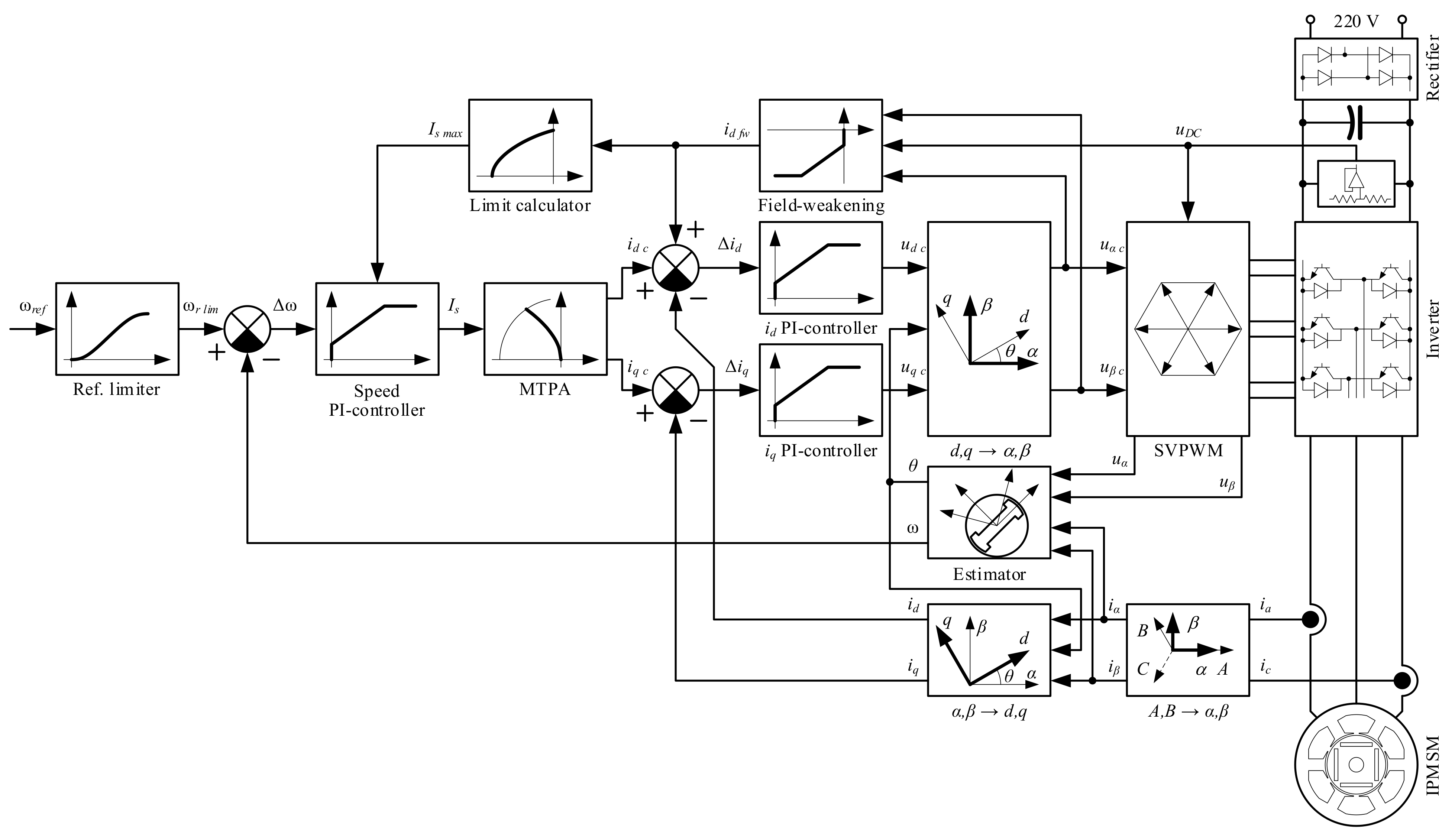
The sensorless vector control system used in this research is shown in Figure 2. It was developed for compressor applications and successfully put into mass production (MP) [35,36]. The system is enhanced by an algorithm that estimates the initial rotor position [37], which is necessary to prevent reverse rotation at start. The control scheme contains an outer speed loop and two inner current loops in dq frame, where current feedback signals are measured by two shunt sensors in the motor phases and electrical position is provided by the estimator. The Space Vector Power Width Modulation (SVPWM) block uses a conventional algorithm along with optimization techniques reported in recent research.
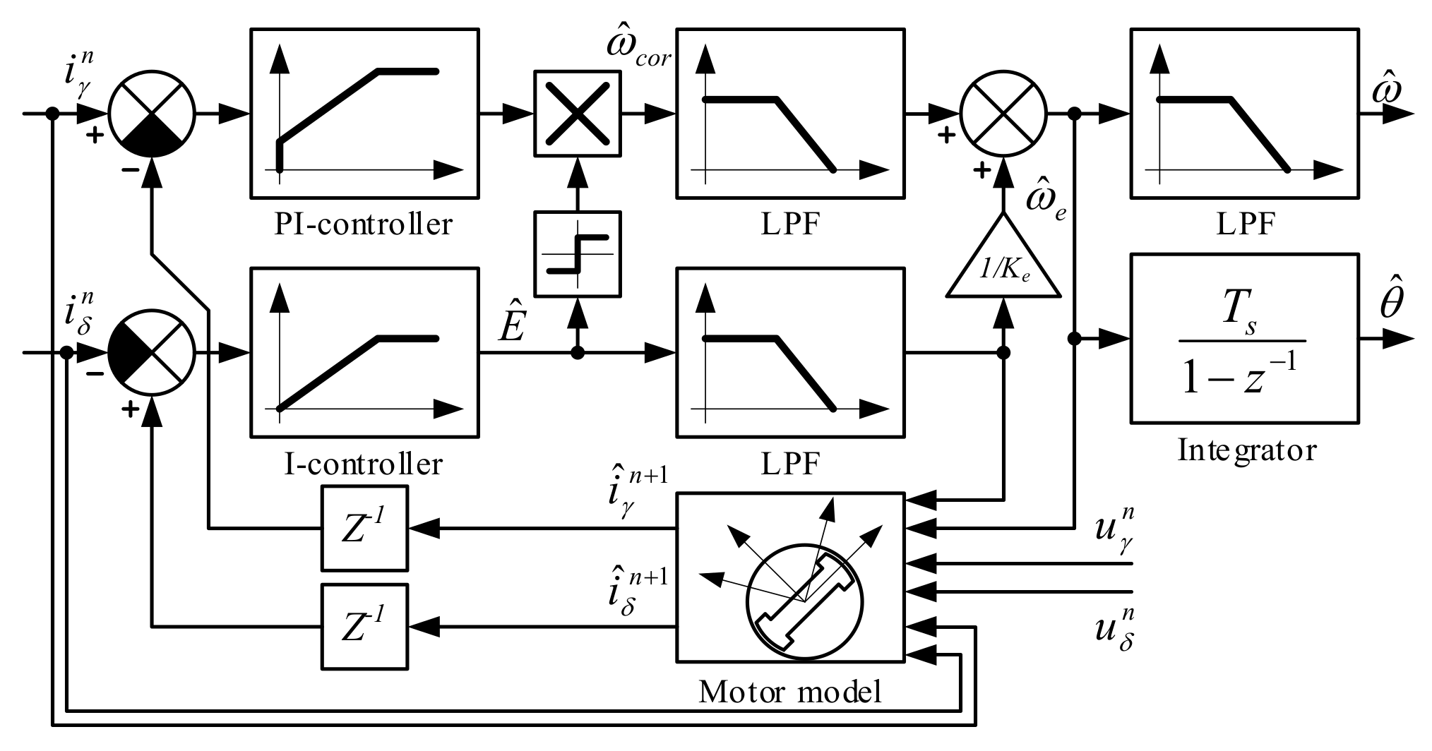
The core of the control algorithm is a back-EMF-based sensorless estimator (Figure 3), which outputs speed and position as necessary for the vector control. It uses the motor model for and electrical values measured at the current calculation step in order to predict motor current at the next calculation step. Then, the current prediction error is used to estimate the motor’s back-EMF (δ-branch) and correct the model uncertainty (γ-branch). The complete analysis of the estimator performance together with its sensitivity to motor parameter variation was considered in detail in [25].
The developed system involves a Maximum Torque Per Ampere (MTPA) algorithm for the full utilization of the motor potential. It receives a current command from the speed controller and decomposes it into direct and quadrature components in order to provide highest possible torque and increase system efficiency.
The control system contains a field-weakening controller for increasing the maximum speed by up to 30% of the rated one by weakening the rotor field with the direct axis current id [38]. Motor condition monitoring is based on the prospective technologies reported in [39,40], which provide reliable protection of the system.
The demonstrated vector control scheme uses an open-loop starting algorithm, which is not shown in Figure 2 and is discussed later.

4. Proposed Method

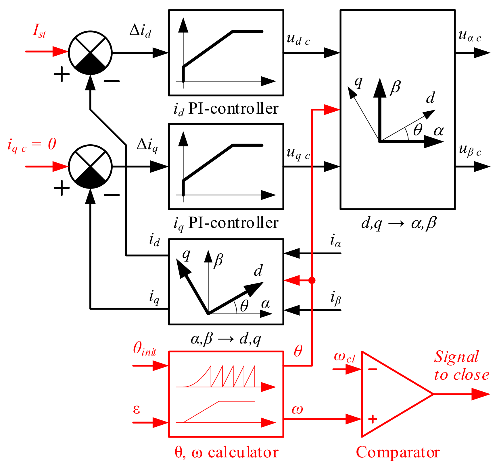
In order to perform open-loop starting, the vector control scheme depicted in Figure 2 was modified as shown in Figure 4 in red. As can be clearly seen, the speed loop was opened and commands for the current controllers were set directly: the quadrature current was set to zero and the direct current was set to be equal to the predefined value Ist. This setting of the currents is a specification of the proposed starting scheme. The most convenient approach is to provide command signals similar to the closed loop control, that is, to set the value of the direct axis current to zero and apply the stator current amplitude to the quadrature axis. However, our experiments demonstrated that setting the initial stator current phase to 0° (aligning along the direct axis) demonstrates less oscillation than setting the current phase to 90° (aligning along the quadrature axis). This is caused by the fact that in the first case (0°), the motor torque rises smoothly from zero to the load torque, while in the second case (90°), the starting torque is applied with a step and then decreases to the load torque. Speed and position are obtained from the calculator, which inputs the predefined initial position θinit and acceleration ε. The open-loop speed is compared with the predefined closing value ωcl, which defines the moment of closing and the activation of the transition algorithm [41].
This closing speed ωcl has to be defined through a series of experiments under different load conditions and deviation of motor parameters at the maximum value of production error.
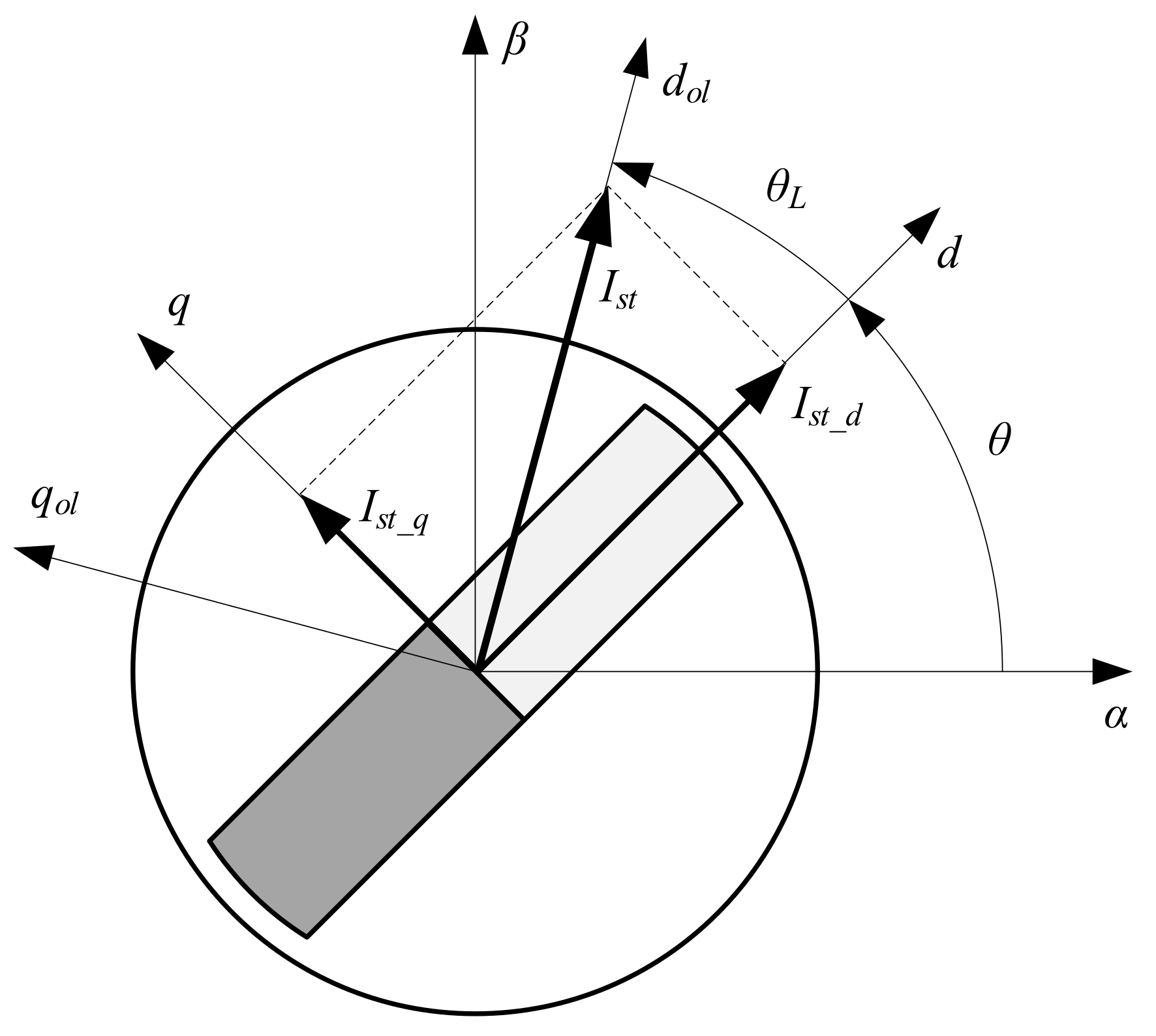
Let us consider the system state immediately prior to closing. Suppose that the starting torque is high enough and the motor operates in synchronism. The stator current vector is applied along the direct axis dol in the synchronous open-loop reference frame dolqol, as shown in Figure 5. This reference frame rotates with the angular speed ω produced by the open-loop calculator. While the rotor of the motor rotates with the same speed, it lags at the load angle θL, which is defined by the load torque comprising the sum of the static load and dynamic torques of the motor. In the simplest case, when the moment of inertia of the system is stable, the load torque is:
T L = T S L + T D = T S L + J Σ ε
where:
TL, TSL–load and static load torques, respectively
TD–dynamic torque
JΣ–total moment of inertia converted to motor side
ε–angular acceleration
Figure 5. Stator current at open-loop starting.
Sustainability 14 12665 g005
Because closing speed is defined as a speed, where the estimator works stably, the position of the real motor synchronous reference frame dq is defined with acceptable tolerance (typically 5~10%). In this frame, the stator starting current Ist has the two components Ist_d and Ist_q shown in Figure 5.
Therefore, for seamless transition, the speed and current controllers must be reinitialized to operate with values in the rotor reference frame dq. Furthermore, this should be performed in one step in order to exclude undesired transients.
Let us consider a PI-type controller, as this is the most popular type of controller for electrical drives and power electronics. Simultaneously, the suggested algorithm of reinitialization may be easily extended to controllers of other types, such as Proportional-Integral-Differential (PID) type controllers. This paper does not pay attention to the tuning of controllers and selection of their gains, because this depends on the exact project in question and is outside the scope of this manuscript. At the same time, the values of the controller gain are not important for reinitialization, which does not depend on them.
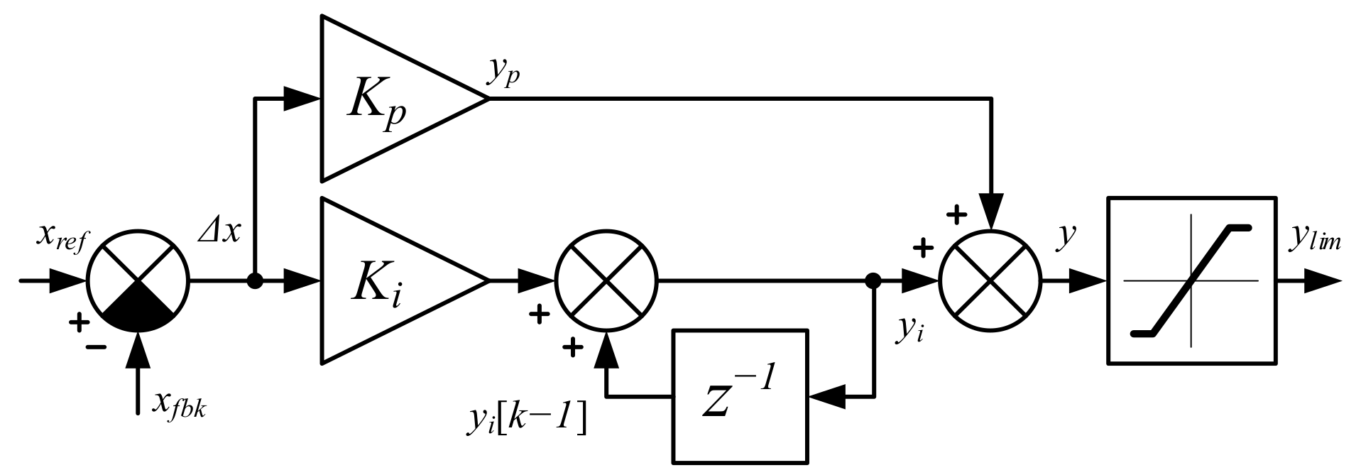
Suppose our system uses PI controllers with proportional and integral gains Kp and Ki, respectively; a typical structure is demonstrated in Figure 6. For the purpose of simplicity, we analyze parallel independent topology without feedforward compensation, which typically does not operate at low speeds. Furthermore, considering that the transition from open-loop to closed-loop control occurs at low speed, the PI controllers are typically far from saturation, therefore, the anti-windup branch is not included in the analysis.
In Figure 6, x and y denote the input and output, respectively, Δx stands for error, yp and yi denote the proportional and integral components of the output, k indicates the current calculation step, and the indexes ref, fbk, and lim are used for reference, feedback, and limited, respectively.
After closing the system, the speed loop starts operation; therefore, the speed controller has to be initialized to correspond to the current state of the system. In order to do this, the following sequence should be executed:
Set the feedback speed ωfbk equal to the output of the estimator;
Set the reference speed to the closing value ωcl;
Calculate the speed error as (ωcl–ωfbk);
Set the output of the speed controller y and its limited value ylim to the current magnitude, which provides the same torque as the torque in the open-loop:
y = I s T ; T = 3 2 P I s t _ q L d L q I s t _ d + Ψ m
where P is number of pole pairs, Ld and Lq are the direct and quadrature inductances, respectively, Ψm is the rotor flux-linkage, and Is(T) is the inverse torque function;
Set proportional component yp equal to the Δω∙Kp;
Set integral component equal to yi = y−yp;
Initialize the integral sum as: yi[k−1] = yi[k]−Δω∙Ki.
After this initialization, the state of the speed controller corresponds to the real state of the motor drive, which excludes undesired speed transients.
It should be noted that the motor parameters in (4) may not be known precisely, which may cause a calculation error. This results in a minor error during reinitialization of the speed controller, which is quickly compensated for. From a practical point of view, the error of about 5~10% in torque calculation does not significantly impact performance. At the same time, the motor torque mainly depends on the rotor flux, which is relatively stable (typical variation due to the temperature change is about 2~3% for rare-earth magnets); thus, the torque error due to motor parameter variation is typically less than 5%.
One more consideration which must be taken into account is that the inverse torque function is quite complicated in analytical form; however, it can be easily approximated even with a second order polynomial for an unsaturated machine. In case of a machine which operates with significant saturation, the 16- or 32-point look-up tables are the most effective solutions. At the same time, for the overwhelming majority of motor drives the difference between direct and quadrature inductances is trivial (10~40%), meaning that the impact of the direct current on the motor torque is not significant. Considering this feature, Equation (4) can be substituted by a simpler equation:
y = I s T I s t _ q
which typically provides an error less than 10%.
The same idea of state equality is used for reinitialization of the current controllers. Suppose that the current control is properly designed and at the moment of closing any electrical transients in the synchronous reference frame are finished. In this case, the current error oscillates slightly around zero and can be neglected. The reference values of the current controllers and their feedbacks have to be set as current components in the synchronous reference frame dq:
i d _ r e f = i d _ f b k = I s t _ d i q _ r e f = i q _ f b k = I s t _ q
which results in zero errors Δid = 0, Δiq = 0. As a result, the proportional components of the PI-controllers are set to zero. The outputs of the current PI-controllers are voltages in the open-loop reference frame dolqol, which are transferred to the stationary reference frame αβ and sent to the SVPWM block for calculation of switch duties. Because voltages uα and uβ produce currents Ist_d and Ist_q, they must stay unchanged. For this purpose, the outputs of the current controllers are initialized with uα and uβ converted back into dq reference frame using estimated angle θ:
u d c = u α c cos θ + u β c sin θ u q c = u α c sin θ + u β c cos θ
Because the errors and proportional component are set to zero, the integral part and integral sum must be set equal to the outputs yi = yi[k−1] = y. Provided the estimation error is acceptable, the type of estimator used to calculate position in (7) does not matter.
Summarizing the reinitialization algorithm of the current controllers, the following sequence is obtained:
Set reference and feedback currents according to (6);
Set current errors Δid and Δid to zero;
Set outputs of the current controllers according to (7);
Set proportional components of the current controllers to zero;
Set integral components equal to outputs.
This reinitialization of current controllers guarantees that the state of the controllers corresponds to the state of the system, thereby excluding undesired transients are. However, it should be noted that the desired current transients may start after closing,. as they tend to set the optimal combination of stator current components, which is produced by the MTPA block. The change of the direct and quadrature current components in this transient depends on the load angle in open-loop mode. Typically, the quadrature current decreases at 10~40% while the direct current decreases at 80~120%, where values higher than 100% correspond to the IPMSMs with Lq > Ld, where the direct current changes polarity.
It should be noted that the desired current transients after closing depend on the tuning of the current controllers; thus, the motor torque during electrical transients does not follow the constant torque curve and slightly deviates from it. A typical example taken from simulation is shown in Figure 7. Simultaneously, the electrical time constant is typically significantly lower than the mechanical one (10~100 times), therefore, electrical transients are much faster than mechanical ones. As a result, electrical transients do not have a significant impact on the mechanical part and the transition may considered seamless and bumpless. However, in systems with low inertia and overregulated current controllers, the real trajectory can significantly differ from the desired trajectory, and can potentially be unacceptable. In such cases, it is recommended to set a connection between the commanded values of current controllers during the period of stabilization in order to provide the desired trajectory immediately after closing.
In this paper, for the sake of simplicity, the structure of the current controller was considered to be quite simple; however, in real systems it may be more complicated. Nevertheless, the proposed considerations are fully applicable to any existing structures and the proposed algorithm needs only minor modifications.

5. Experimental System

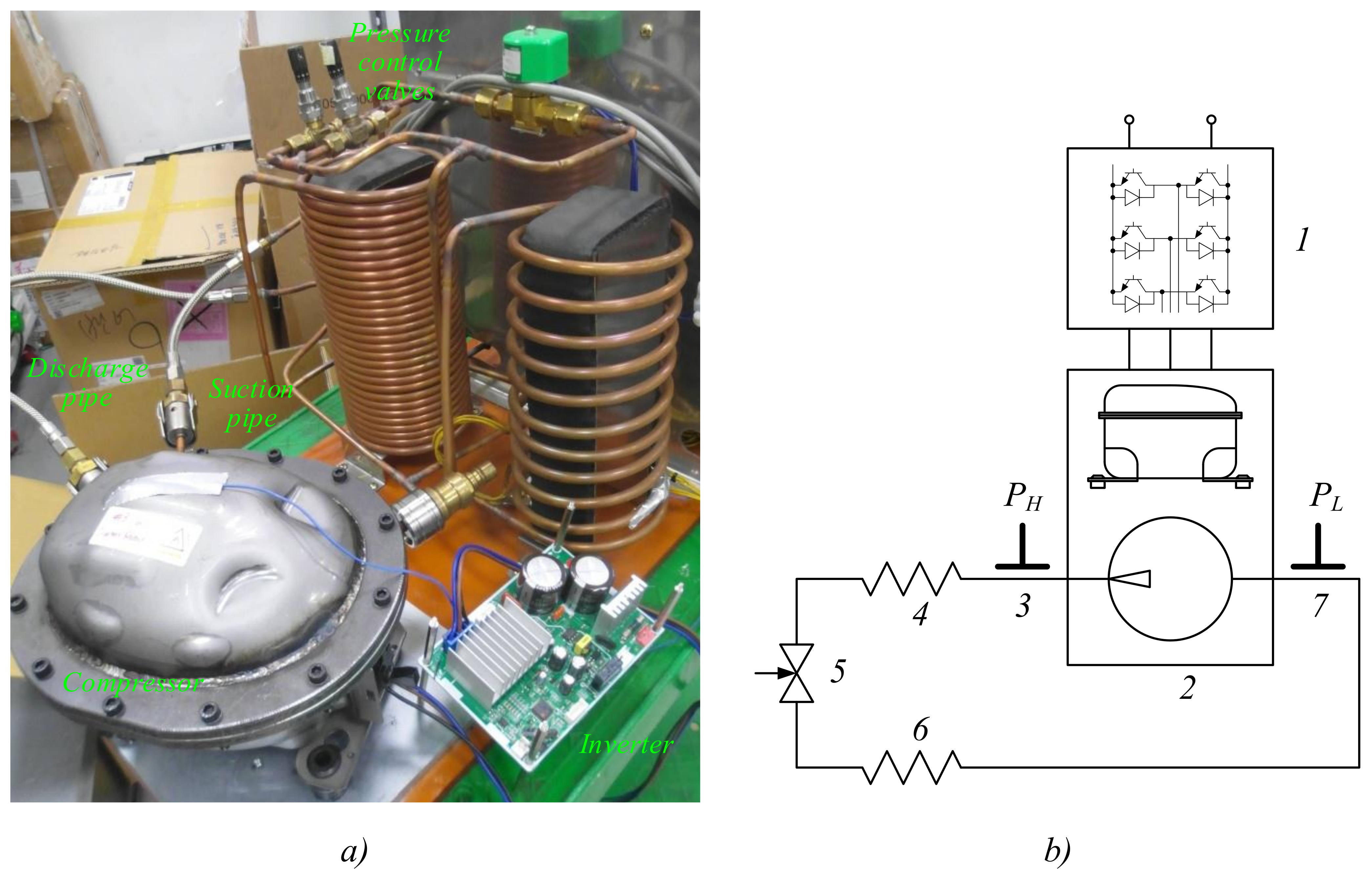
The experimental system used for verification of the proposed technique is shown in Figure 8, where Figure 8a demonstrates a view of the installation and Figure 8b depicts its schematic. In this figure, Inverter 1 supplies Compressor 2, which pumps a refrigerant. Air Condenser 4 cools the pressurized refrigerant, while Evaporator 6 decreases the pressure and temperature of the refrigerant. Valve 5 controls operation of the compressing circuit by setting the pressure of the refrigerant. Manometers 3 and 7 are used to control high and low pressures, respectively.
The reciprocating compressor is a commercial device used in many models of refrigerators; it was equipped with additional flanges in order to provide access to the inner space. The compressor is driven with an IPMSM motor design according to [42] and optimized using the approach considered in [43], the parameters of which are shown in Table 1. The inverter board is of a mass produced type of unit which is used in commercial refrigerators and air conditioners. It uses a three-phase intelligent module STGIPN3H60 (3 A/600 V) from “ST Microelectronics” containing six MOSFETs and gating circuits. It was designed to be supplied from a standard 220 V (50–60) Hz source. The control system is built on the base of a 60 MIPS Cortex-M3 microcontroller, which controls the inverter with 4 kHz PWM. Electrical signals are sensed by the DC-link voltage sensor and two current sensors, which are converted by a 12-bit ADC microcontroller with a sampling time of 250 μs.
The software of the inverter board is based on the MP code, which was enhanced for debugging. It contains a sensorless control scheme with the proposed open-loop starting algorithm described above along with additional debugging and monitoring interfaces. The current PI controllers were implemented as described in [44], which provides a better dynamic. Square root calculations were optimized according to [45], which decreases the load to the MCU and makes implementation of this control system possible in low cost systems. The abnormal voltage protections were implemented as described in [46,47,48].
The estimator used in the experiments was an-EMF based algorithm, which has been considered in detail in [25]. Its performance was verified on the dynamo test set using the methods discussed in [49,50], showing that the estimation algorithm operates stably at speeds over 10 Hz with an estimation error not exceeding five electrical degrees.

6. Experimental Results

In order to verify the feasibility of the proposed method and check its performance, a series of experiments were conducted. Because the compressor was not equipped with a position sensor, the direct and quadrature currents were calculated using the estimated angle; thus, while these values are not precise at low speeds, they provide enough information to illustrate transients.
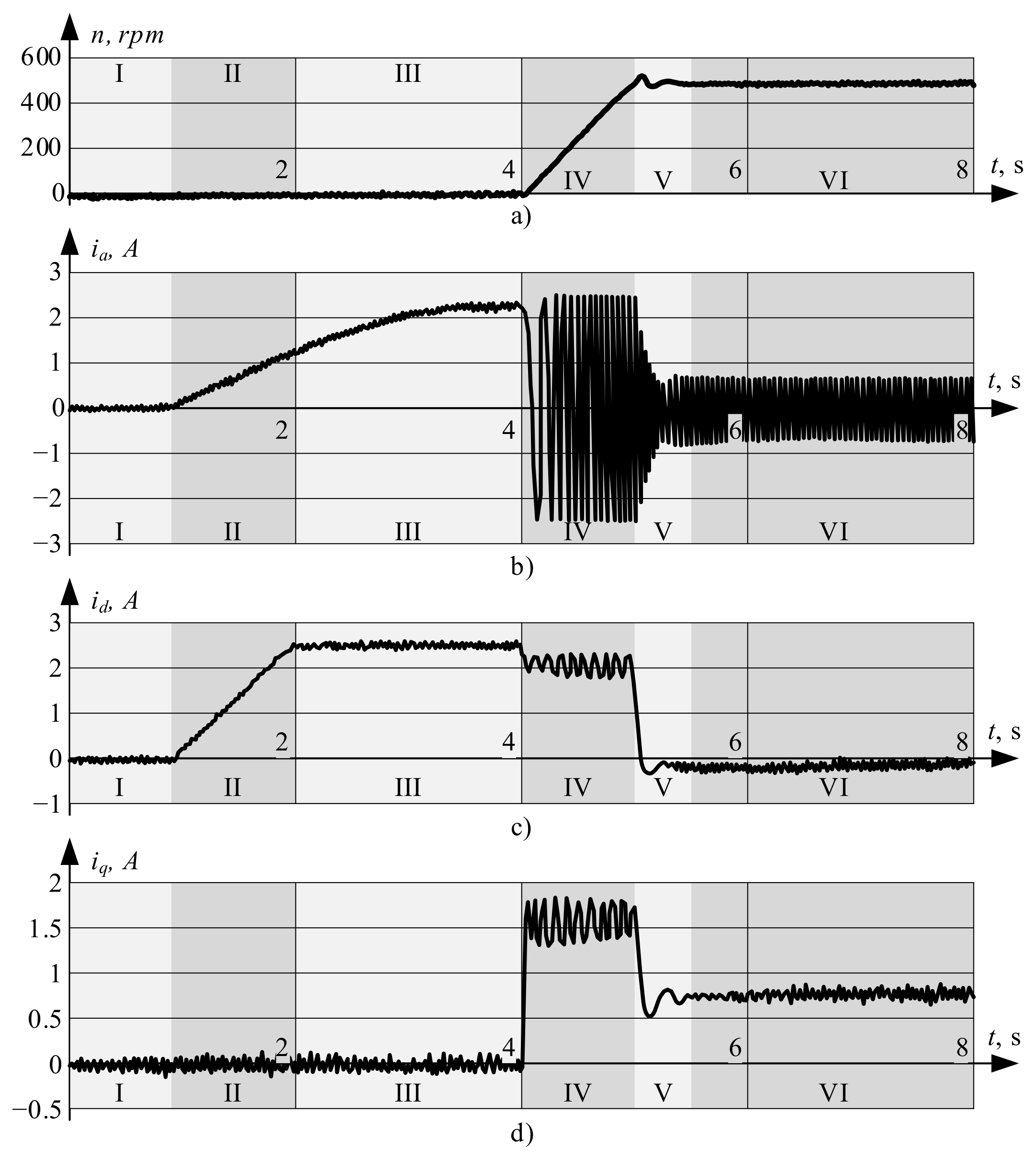
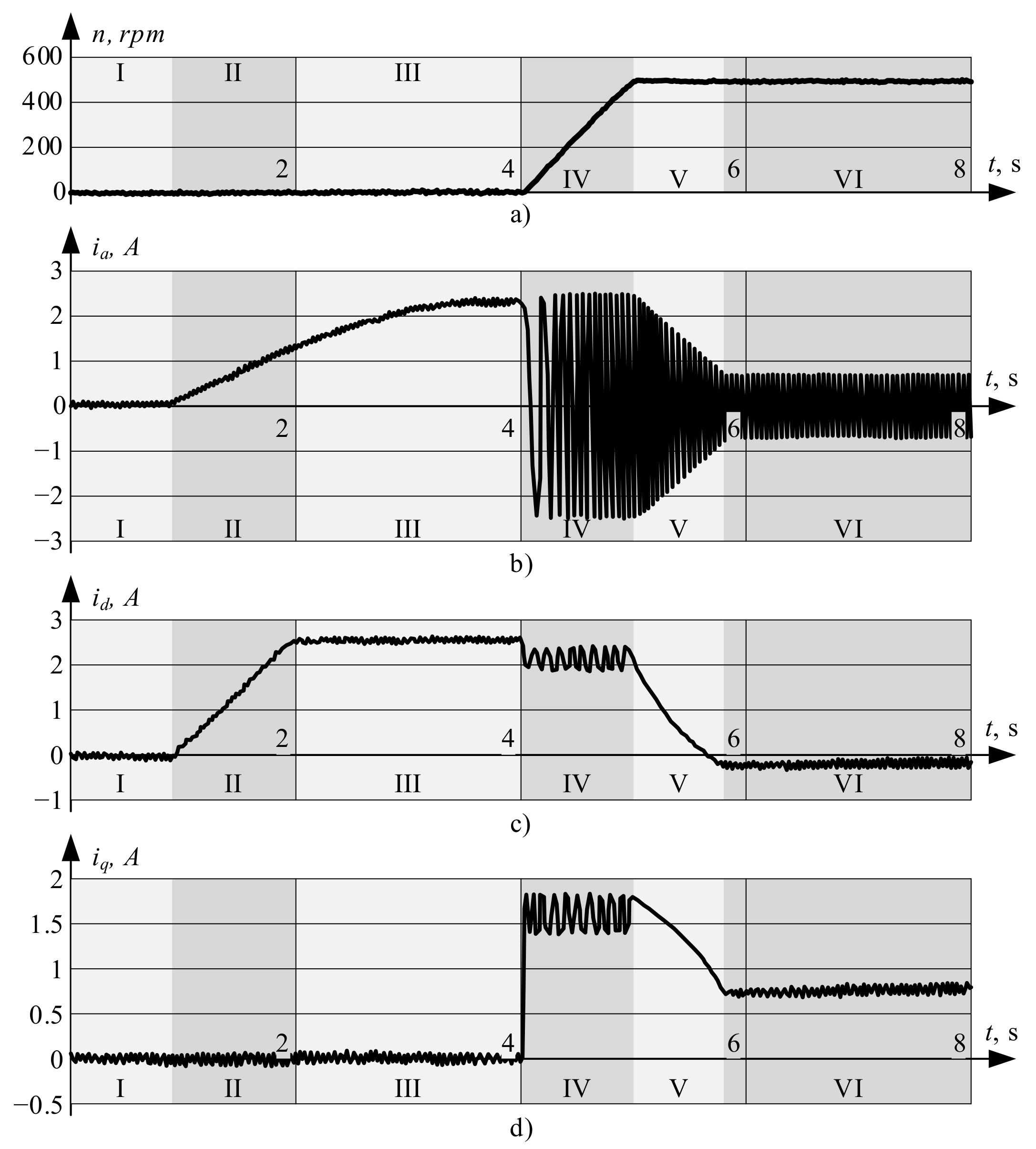
In the first experiment, the target system with reciprocating compressor was started in open-loop mode at the rated load. After acceleration and stable operation of the estimator, it was closed and switched to sensorless mode. The transition was implemented using Equation (4), with the inverse torque function implemented using the 32-bit table. The motor currents in this mode of operation are shown in Figure 9, where Figure 9a illustrates the compressor speed and Figure 9b, c, and d demonstrate the phase, direct, and quadrature currents, respectively. The start procedure consists of the following steps:
  • Charging of the inverter bootstrapping capacitors;
  • Rotor positioning: rise in current from zero to starting value at a fixed angle of −60°;
  • Rotor positioning: rotation of the stator current from −60° to 0°;
  • Open-loop starting;
  • Transients after closing;
  • Normal operation in sensorless mode.
As can be clearly seen, there are no undesired transients after starting; only minor oscillations are present, and these do not significantly impact the system.
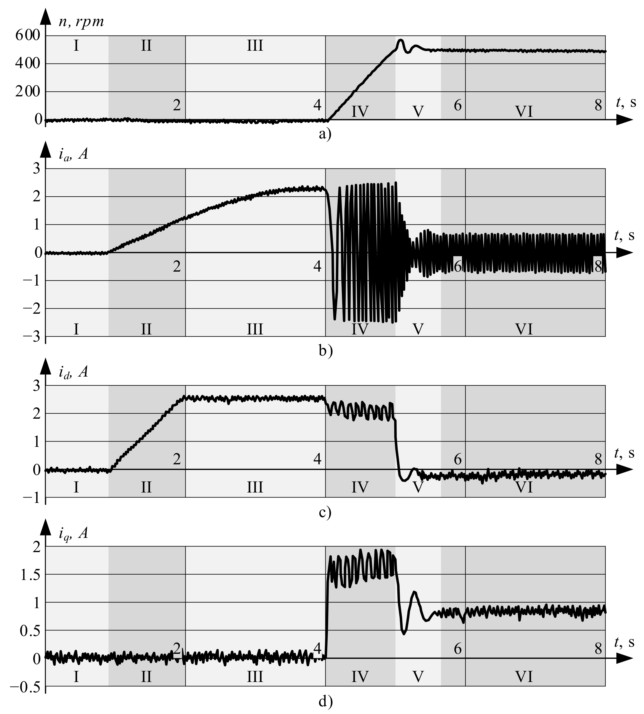
In the next experiment, the reinitialization of the speed controller was implemented using a simplified formula (5) which significantly simplifies calculations, although it provides slightly increased torque immediately after closing. While this torque is easily compensated for by the speed controller, it results in more significant transients; see Figure 10, where Figure 10a illustrates compressor speed and Figure 10b–d demonstrate the phase, direct, and quadrature currents, respectively Nevertheless, as it is acceptable for the overwhelming majority of motor drives and does not impact the system significantly, this method can be considered for implementation in low-cost systems.
Simultaneously, if these short transients are unacceptable due to the lower drive inertia or other criteria, the desired current trajectory, which follows constant torque loci after closing, should be followed. This process is illustrated in Figure 11, where Figure 11a illustrates compressor speed, Figure 11b–d demonstrate phase, direct, and quadrature currents, respectively. As can be clearly seen, there are no current oscillations and the stator current vector follows the constant torque loci. The transition along constant torque loci was intentionally set to 0.8 s in order to demonstrate it clearly. In a real system it can be selected within the range of 0.01~0.05 s.
Finally, the performance of the proposed technique was compared with the conventional algorithms. In order to do this, the same experimental system was used and only the transition algorithm was modified, according to recommendations in previous works. The comparison results are presented in Table 2, which demonstrates that the proposed methods are superior to the existing technologies and provide instant closing with acceptable deviation of control parameters.

7. Discussion

The experimental results provided above demonstrate that the proposed technique is superior to the conventional algorithms. It can perform instant reinitialization of system controllers from the open-loop reference frame used at start to the estimated synchronous reference frame, where the control system operates after closing. At the same time, conventional techniques involve cross-over functions, which require about 0.5 ~ 0.8 s for switching. In this interval the conventional control system may not execute external commands, which results in poor controllability. Furthermore, due to the use of cross-over functions, the transients are higher and longer.
The proposed algorithm reinitializes system controllers in such a way that their new state corresponds to the system state in a new reference frame. This action is performed in one calculation step, thereby avoiding undesired transients, and the system is ready to process external commands immediately after reinitialization.
The speed and current transients which occur in the experimental system are caused by the change of the operational point. The system moves from the starting point, which corresponds to a higher stator current and lower efficiency, to the optimal working point with the lowest current and highest efficiency, as shown in Figure 7. As this process may be uncontrolled, the current controllers set the current in the fastest way, which results in slight deviation from the torque loci curve and minor transients. These transients are accepted for the overwhelming majority of motor drives; however, if transients are undesired the currents may be controlled to follow the torque loci curve. In this case, the system moves from one operational point to another without transients.

8. Conclusions

This paper proposes an algorithm for instant and seamless closing of control systems of synchronous motors after open-loop starting. The author has reviewed and discussed existing methods of sensorless motor starting and considered existing techniques utilized for transitioning from open-loop mode to sensorless vector control. After concluding that existing methods were inapplicable, the new method was proposed and implemented. In this algorithm, PI-controllers start operation in the open-loop synchronous frame and operate there until the decision to close the control systems is made. Afterwards, all internal variables of the PI-controllers are reinitialized to operate in the estimated synchronous reference frame in which the control system works after starting. The proposed algorithm suggests several approaches to calculate motor torque and perform seamless closing. Furthermore, the author proposes several ways to switch the system from the operational point used before closing to the optimal operational point used in further operation. These approaches differ in the complexity of their implementation and in speed transients; the most convenient solution may thus be selected for different projects depending on their requirements. The experimental results prove the feasibility of this proposal and the absence of undesired transients.

Funding

This research and APC were funded by Anton Dianov.

Institutional Review Board Statement

Not applicable.

Informed Consent Statement

Not applicable.

Data Availability Statement

Not applicable.

Conflicts of Interest

The author declares no conflict of interest.

References

  1. Raud, Z.; Vodovozov, V.; Lillo, N.; Rassolkin, A. Reserves for regenerative braking of battery electric vehicles. In Proceedings of the 2014 Electric Power Quality and Supply Reliability Conference (PQ), Rakvere, Estonia, 11–13 June 2014; pp. 189–194. [Google Scholar] [CrossRef]
  2. Ibrahim, M.; Rassõlkin, A.; Vaimann, T.; Kallaste, A. Overview on Digital Twin for Autonomous Electrical Vehicles Propulsion Drive System. Sustainability 2022, 14, 601. [Google Scholar] [CrossRef]
  3. Lukin, A.; Demidova, G.; Rassõlkin, A.; Lukichev, D.; Vaimann, T.; Anuchin, A. Small Magnus Wind Turbine: Modeling Approaches. Appl. Sci. 2022, 12, 1884. [Google Scholar] [CrossRef]
  4. Iqbal, M.; Kütt, L.; Lehtonen, M.; Millar, R.; Püvi, V.; Rassõlkin, A.; Demidova, G. Travel Activity Based Stochastic Modelling of Load and Charging State of Electric Vehicles. Sustainability 2021, 13, 1550. [Google Scholar] [CrossRef]
  5. Goman, V.; Prakht, V.; Kazakbaev, V.; Dmitrievskii, V. Comparative Study of Induction Motors of IE2, IE3 and IE4 Efficiency Classes in Pump Applications Taking into Account CO2 Emission Intensity. Appl. Sci. 2020, 10, 8536. [Google Scholar] [CrossRef]
  6. Gevorkov, L.; Rassõlkin, A.; Kallaste, A.; Vaimann, T. Simulation Study of a Centrifugal Pumping Plant’s Power Consumption at Throttling and Speed Control. In Proceedings of the 2017 IEEE 58th International Scientific Conference on Power and Electrical Engineering of Riga Technical University (RTUCON), Riga, Latvia, 12–13 October 2017; pp. 1–5. [Google Scholar]
  7. Goman, V.; Prakht, V.; Kazakbaev, V.; Dmitrievskii, V. Comparative Study of Energy Consumption and CO2 Emissions of Variable-Speed Electric Drives with Induction and Synchronous Reluctance Motors in Pump Units. Mathematics 2021, 9, 2679. [Google Scholar] [CrossRef]
  8. Goman, V.; Oshurbekov, S.; Kazakbaev, V.; Prakht, V.; Dmitrievskii, V. Energy Efficiency Analysis of Fixed-Speed Pump Drives with Various Types of Motors. Appl. Sci. 2019, 9, 5295. [Google Scholar] [CrossRef] [Green Version]
  9. Bolognani, S.; Petrella, R.; Prearo, A.; Sgarbossa, L. Automatic tracking of MTPA trajectory in IPM motor drives based on AC current injection. IEEE Trans. Ind. Appl. 2011, 47, 105–114. [Google Scholar] [CrossRef]
  10. Qiang, G.; Wei, W.; Rongjie, R.; Dianguo, X. Design of IMC controller with anti-saturation for PMSM compressor system. In Proceedings of the 2008 IEEE Vehicle Power and Propulsion Conference, Harbin, China, 3–5 September 2008; pp. 1–5. [Google Scholar] [CrossRef]
  11. Fatu, M.; Teodorescu, R.; Boldea, I.; Andreescu, G.D.; Blaabjerg, F. I-F starting method with smooth transition to EMF based motion-sensorless vector control of PM synchronous motor/generator. In Proceedings of the 2008 IEEE Power Electronics Specialists Conference, Rhodes, Greece, 15–19 June 2008; pp. 1481–1487. [Google Scholar] [CrossRef]
  12. Yun, S.Y.; Lee, H.J.; Lee, J.J.; Kim, I.G.; Lee, J. Research on the starting methods for initial driving of PMSM. In Proceedings of the 2012 15th International Conference on Electrical Machines and Systems (ICEMS), Sapporo, Japan, 21–24 October 2012; pp. 1–5. [Google Scholar]
  13. Lee, W.J.; Sul, S.K. A new starting method of BLDC motors without position sensor. In Proceedings of the Conference Record of the 2004 IEEE Industry Applications Conference, 2004. 39th IAS Annual Meeting, Seattle, WA, USA, 3–7 October 2004. [Google Scholar] [CrossRef]
  14. Wu, S.; Li, Y.; Miao, X. Comparison of signal injection methods for sensorless control of PMSM at very low speeds. In Proceedings of the 2007 European Conference on Power Electronics and Applications, Aalborg, Denmark, 2–5 September 2007; pp. 1–6. [Google Scholar] [CrossRef]
  15. Wang, G.; Xiao, D.; Zhao, N.; Zhang, X.; Wang, W.; Xu, D. Low-Frequency Pulse Voltage Injection Scheme-Based Sensorless Control of IPMSM Drives for Audible Noise Reduction. IEEE Trans. Ind. Electron. 2017, 64, 8415–8426. [Google Scholar] [CrossRef]
  16. Kereszty, T.; Leppanen, V.M.; Luomi, J. Sensorless control of surface magnet synchronous motors at low speeds using low-frequency signal injection. In Proceedings of the IECON’03. 29th Annual Conference of the IEEE Industrial Electronics Society, Roanoke, VA, USA, 2–6 November 2003; pp. 1239–1243. [Google Scholar] [CrossRef]
  17. Basic, D.; Malrait, F.; Rouchon, P. Current Controller for Low-Frequency Signal Injection and Rotor Flux Position Tracking at Low Speeds. IEEE Trans. Ind. Electron. 2010, 58, 4010–4022. [Google Scholar] [CrossRef] [Green Version]
  18. Lee, K.W.; Kim, D.K.; Kim, B.T.; Kwon, B.I. A Novel Starting Method of the Surface Permanent-Magnet BLDC Motors Without Position Sensor for Reciprocating Compressor. IEEE Trans. Ind. Appl. 2008, 44, 85–92. [Google Scholar] [CrossRef]
  19. Kim, D.K.; Rhyu, S.H.; Lee, K.W.; Kim, B.T.; Chung, D.H.; Kwon, B.I. Comparison of Starting Method for Position Sensorless BLDC Motor Driven Reciprocating Compressor. In Proceedings of the 2008 IEEE Industry Applications Society Annual Meeting, Edmonton, AB, Canada, 5–9 October 2008; pp. 1–6. [Google Scholar] [CrossRef]
  20. Fu, Y.J.; Huang, L.T.; Lin, R.Y.; Chen, C.H. Reliable starting method for sensorless brushless dc motor drive. In Proceedings of the 2012 IEEE/ASME International Conference on Advanced Intelligent Mechatronics (AIM), Kaohsiung, Taiwan, 11–14 July 2012. [Google Scholar] [CrossRef]
  21. Lin, S.; Bi, C.; Jiang, Q.; Phyu, H.N. Analysis of three synchronous drive modes for the starting performance of spindle motors. IEEE Trans.Magn. 2007, 43, 3734–3737. [Google Scholar] [CrossRef]
  22. Marcic, T.; Stumberger, B.; Stumberger, G. Comparison of Induction Motor and Line-Start IPM Synchronous Motor Performance in a Variable-Speed Drive. IEEE Trans. Ind. Appl. 2012, 48, 2341–2352. [Google Scholar] [CrossRef]
  23. Rachev, E.; Petrov, V. An Approach to Solving Ramp Start Issues in Sensorless Field Oriented Control with Sliding Mode Observer for Permanent Magnet Synchronous Motors. In Proceedings of the 2019 16th Conference on Electrical Machines, Drives and Power Systems (ELMA), Varna, Bulgaria, 6–8 June 2019; pp. 1–4. [Google Scholar] [CrossRef]
  24. Liu, J.; Nondahl, T.A.; Dai, J.; Royak, S.; Schmidt, P.B. A Seamless Transition Scheme of Position Sensorless Control in Industrial Permanent Magnet Motor Drives With Output Filter and Transformer for Oil Pump Applications. IEEE Trans. Ind. Appl. 2020, 56, 2180–2189. [Google Scholar] [CrossRef]
  25. Dianov, A.; Young-Kwan, K.; Sang-Joon, L.; Sang-Taek, L.; Tae-Ho, Y. Sensorless IPMSM based drive for reciprocating compressor. In Proceedings of the 2008 13th International Power Electronics and Motion Control Conference, Poznan, Poland, 1–3 September 2008; pp. 1002–1008. [Google Scholar] [CrossRef]
  26. Xiaohan, M.; Xiaolin, W.; Zhiquan, D.; Pengfei, Z.; Yao, Z. Position sensorless starting method of BLDC motor based on SVPWM and stator magnetomotive force control. In Proceedings of the IECON 2013—39th Annual Conference of the IEEE Industrial Electronics Society, Vienna, Austria, 10–13 November 2013; pp. 3054–3059. [Google Scholar] [CrossRef]
  27. Nair, S.V.; Hatua, K.; Prasad, N.D.; Reddy, D.K. A Smooth and Stable Open-Loop I-F Control for a Surface Mount PMSM Drive by Ensuring Controlled Starting Torque. In Proceedings of the IECON 2018—44th Annual Conference of the IEEE Industrial Electronics Society, Washington, DC, USA, 21–23 October 2018; pp. 355–360. [Google Scholar] [CrossRef]
  28. Nair, S.V.; Hatua, K.; Prasad, N.V.P.R.D.; Reddy, D.K. A Quick If Starting of PMSM Drive With Pole Slipping Prevention and Reduced Speed Oscillations. IEEE Trans. Ind. Electron. 2020, 68, 6650–6661. [Google Scholar] [CrossRef]
  29. Li, Z.; Zhang, Q.; Luo, H.; Wang, H.; Wang, J.; Han, F.; Wang, A.; Liu, X.; Yu, X.; Zhou, L. Sensorless Starting Control of Permanent Magnet Synchronous Motors with Step-up Transformer for Downhole Electric Drilling. In Proceedings of the IECON 2018—44th Annual Conference of the IEEE Industrial Electronics Society, Washington, DC, USA, 21–23 October 2018; pp. 689–694. [Google Scholar] [CrossRef]
  30. Jiang, D.; Lai, R.; Wang, F.; Burgos, R.; Boroyevich, D. Start-up transient improvement for sensorless control approach of PM motor. In Proceedings of the 2010 Twenty-Fifth Annual IEEE Applied Power Electronics Conference and Exposition (APEC), Palm Springs, CA, USA, 21–25 February 2010; pp. 408–413. [Google Scholar] [CrossRef]
  31. Xu, P.; Zhu, Z.Q. Novel Carrier Signal Injection Method Using Zero Sequence Voltage for Sensorless Control of PMSM Drives. IEEE Trans. Ind. Electron. 2015, 63, 2053–2061. [Google Scholar] [CrossRef]
  32. Pacha, M.; Zossak, S. Improved Simple I-F Open-Loop Start-up of PMSM Drives Without Speed or Position Sensor. In Proceedings of the 2019 IEEE 10th International Symposium on Sensorless Control for Electrical Drives (SLED), Turin, Italy, 9–10 September 2019; pp. 1–6. [Google Scholar] [CrossRef]
  33. Baratieri, C.L.; Pinheiro, H. An I-F starting method for smooth and fast transition to sensorless control of BLDC motors. In Proceedings of the 2013 Brazilian Power Electronics Conference, Gramado, Brazil, 27–31 October 2013; pp. 836–843. [Google Scholar] [CrossRef]
  34. Dianov, A. Estimation of the Mechanical Position of Reciprocating Compressor for Silent Stoppage. IEEE Open J. Power Electron. 2020, 1, 64–73. [Google Scholar] [CrossRef]
  35. Lee, S.T.; Kim, H.J.; Kim, D.K.; Lee, K.W. A novel load variation compensation algorithm in a sensor-less brushless DC motor drive for a reciprocating compressor. In Proceedings of the INTELEC 2009—31st International Telecommunications Energy Conference, Incheon, Korea, 18–22 October 2009; pp. 1–4. [Google Scholar] [CrossRef]
  36. Dianov, A.; Kim, N.S.; Lim, S.M. Sensorless starting of horizontal axis washing machines with direct drive. In Proceedings of the 2013 International Conference on Electrical Machines and Systems (ICEMS), Busan, Korea, 26–29 October 2013; pp. 1–6. [Google Scholar] [CrossRef]
  37. Dianov, A.; Anuchin, A.S.; Kozachenko, V.F. Initial rotor position detection of PM motors. In Proceedings of the EPE Power Electronics and Motion Control Conference, Riga, Latvia, 2–4 September 2004; pp. 1–6. [Google Scholar]
  38. Dianov, A. Optimized Field-Weakening Strategy for Control of PM Synchronous Motors. In Proceedings of the 2022 29th International Workshop on Electric Drives: Advances in Power Electronics for Electric Drives (IWED), Moscow, Russian, 26–29 January 2022; pp. 1–6. [Google Scholar]
  39. Kudelina, K.; Vaimann, T.; Asad, B.; Rassõlkin, A.; Kallaste, A.; Demidova, G. Trends and Challenges in Intelligent Condition Monitoring of Electrical Machines Using Machine Learning. Appl. Sci. 2021, 11, 2761. [Google Scholar] [CrossRef]
  40. Demidova, G.L.; Kallaste, A.; Kuts, V.; Orosz, T.; Rassõlkin, A.; Rjabtšikov, V.; Vaimann, T. Implementation of Digital Twins for electrical energy conversion systems in selected case studies. Proc. Estonian Acad. Sci. 2021, 70, 19. [Google Scholar] [CrossRef]
  41. Dianov, A. Instant and seamless closing of control system of IPMSM after open-loop starting. In Proceedings of the 2021 XVIII International Scientific Technical Conference Alternating Current Electric Drives (ACED), Ekaterinburg, Russia, 24–27 May 2021; pp. 1–6. [Google Scholar] [CrossRef]
  42. Dmitrievskii, V.; Prakht, V.; Kazakbaev, V.; Sarapulov, S. Optimal Design of a High-Speed Single-Phase Flux Reversal Motor for Vacuum Cleaners. Energies 2018, 11, 3334. [Google Scholar] [CrossRef] [Green Version]
  43. Dmitrievskii, V.; Prakht, V.; Kazakbaev, V. IE5 Energy-Efficiency Class Synchronous Reluctance Motor With Fractional Slot Winding. IEEE Trans. Ind. Appl. 2019, 55, 4676–4684. [Google Scholar] [CrossRef]
  44. Anuchin, A.; Dianov, A.; Kozachenko, V. Adaptive efficient control for switch-reluctance drives with DCDC-regulator for inverter supply. In Proceedings of the EPE Power Electronics and Motion Control Conference, Riga, Latvia, 2–4 September 2004; pp. 1–5. [Google Scholar]
  45. Dianov, A.; Anuchin, A. Review of fast square root calculation methods for fixed point microcontroller-based control systems of power electronics. Int. J. Power Electron. Drive Syst. 2020, 11, 1153–1164. [Google Scholar] [CrossRef]
  46. Do, H.D.; Anuchin, A.; Shpak, D.; Zharkov, A.; Rusakov, A. Overvoltage protection for interior permanent magnet synchronous motor testbench. In Proceedings of the 2018 25th International Workshop on Electric Drives: Optimization in Control of Electric Drives (IWED), Moscow, Russia, 31 January–2 February 2018; pp. 1–4. [Google Scholar] [CrossRef]
  47. Anuchin, A.; Il’In, G.; Belyakov, G.; Shpak, D. Insulation monitoring system for electric drives in TN networks. In Proceedings of the 2017 International Conference on Modern Power Systems (MPS), Cluj-Napoca, Cluj-Napoca, Romania, 6–9 June 2017; pp. 1–4. [Google Scholar] [CrossRef]
  48. Yakovenko, M.; Anuchin, A.; Ostrirov, V.; Milskiy, K. Implementation of a Protected Low-Cost Voltage-Source Inverter. In Proceedings of the 2018 X International Conference on Electrical Power Drive Systems (ICEPDS), Novocherkassk, Russia, 3–6 October 2018; pp. 1–4. [Google Scholar] [CrossRef]
  49. Anuchin, A.; Dianov, A.; Shpak, D.; Astakhova, V.; Fedorova, K. Speed estimation algorithm with specified bandwidth for incremental position encoder. In Proceedings of the 2016 17th International Conference on Mechatronics-Mechatronika (ME), Prague, Czech Republic, 7–9 December 2016; pp. 1–6. [Google Scholar]
  50. Anuchin, A.; Dianov, A.; Briz, F. Synchronous Constant Elapsed Time Speed Estimation Using Incremental Encoders. IEEE/ASME Trans. Mechatronics 2019, 24, 1893–1901. [Google Scholar] [CrossRef]
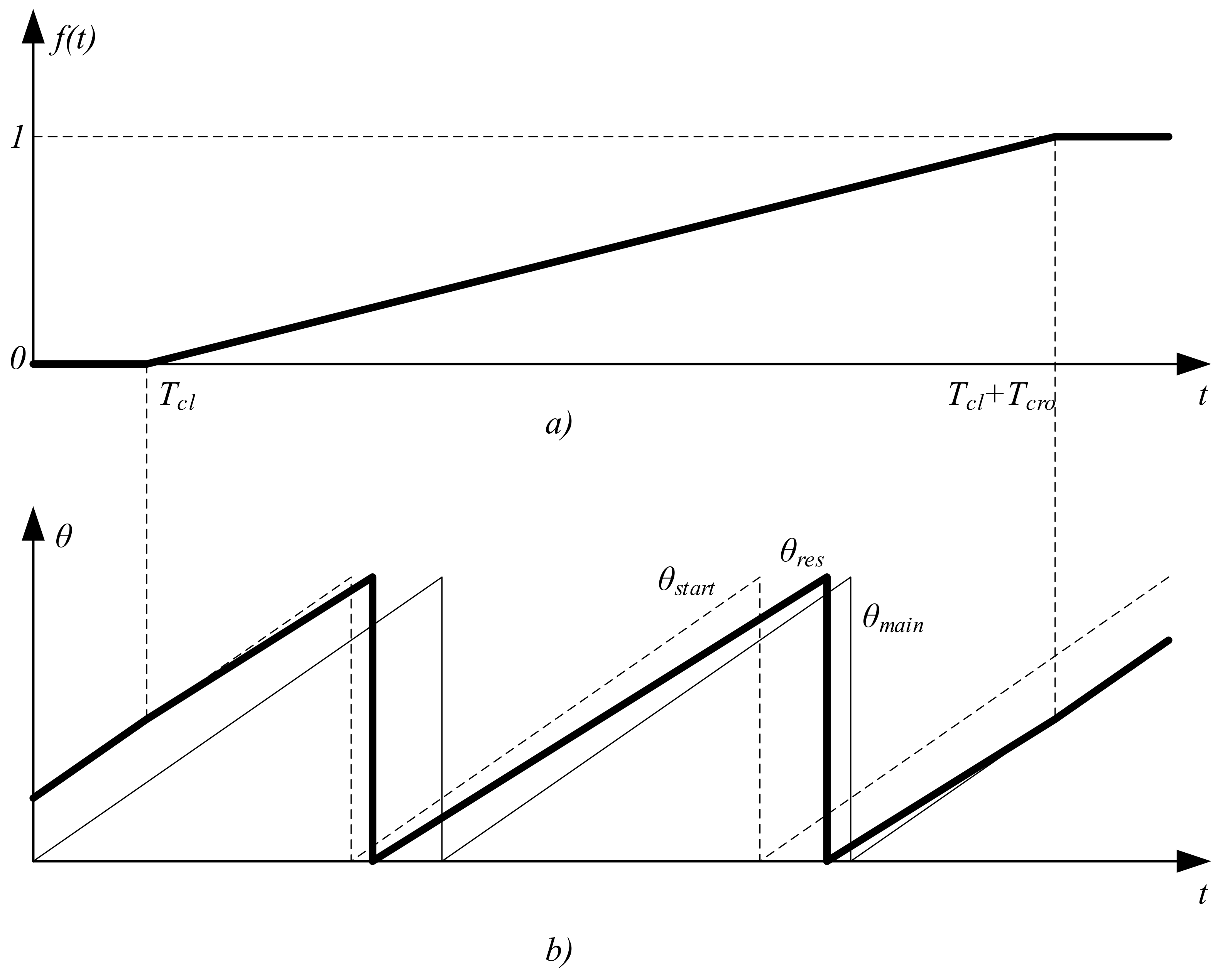
Figure 1. Cross-over transient: (a) transient function and (b) electrical positions.
Sustainability 14 12665 g001
Figure 2. Sensorless vector control scheme of the reciprocating compressor drive.
Sustainability 14 12665 g002
Figure 3. Back-EMF-based estimator.
Sustainability 14 12665 g003
Figure 4. Control scheme modification for open-loop starting.
Sustainability 14 12665 g004
Figure 6. PI controller.
Sustainability 14 12665 g006
Figure 7. Trajectory after closing.
Sustainability 14 12665 g007
Figure 8. Experimental setup: (a) picture and (b) schematic.
Sustainability 14 12665 g008
Figure 9. Motor currents at start when closing is performed using (4): (a) compressor speed, (b) phase current, (c) direct current, (d) quadrature current.
Sustainability 14 12665 g009
Figure 10. Motor currents at start when closing is performed using (5): (a) compressor speed, (b) phase current, (c) direct current, (d) quadrature current.
Sustainability 14 12665 g010
Figure 11. Motor currents at start with trajectory control: (a) compressor speed, (b) phase current, (c) direct current, (d) quadrature current.
Sustainability 14 12665 g011
Table 1. Experimental motor parameters.
ParameterValue
Pole pairs, p3
Stator resistance, Rs [Ω]7.2
Direct axis inductance, Ld [mH]77
Quadrature axis inductance, Lq [mH]117
Flux linkage, ψ [V/rad/s]0.143
Rated speed, ωrated [rpm]4000
Rated power, Prated [W]200
Table 2. Comparison of the proposed and existing methods.
 ParameterCross-Over TimeSpeed
Deviation
Current
Deviation
Method 
Proposed (Equation (4)), Figure 9)Instant30 rpm0.3 A
Proposed, trajectory (Figure 11)Instant<8 rpm<0.05 A
Cross-over (Equation (1))0.5 s50 rpm0.2 A
Cross-over (Equation (2))0.8 s45 rpm0.15 A
Publisher’s Note: MDPI stays neutral with regard to jurisdictional claims in published maps and institutional affiliations.