1. Introduction
Coal-fired power generation is currently the main form of power generation in thermal power plants, and the coal burning in boilers produces large amounts of nitrogen oxides (NO
x), which are absorbed by rain and snow as they fall and are generated in the atmospheric system, resulting in acid rain that can cause building corrosion and crop death, thus affecting the sustainability of natural resources. NO
x also reacts photochemically with other pollutants in the ultraviolet light, creating secondary pollutants known as photochemical smog pollution. If it encounters fine particles in the air, it will form PM2.5, thus endangering the survival of animals and agricultural crops, thus destroying the balance of the ecosystem and causing significant pollution to the environment. So, NO
x emissions from thermal power plants have been under strict supervision. In China, it has been required that NO
x emissions be reduced to below 50 mg/m
3. On the one hand, the valve life is easily affected by the frequent action of the NH
3 injection valve. On the other hand, if the NH
3 injection is less frequent, it is easy to cause the outlet NO
x to exceed the national environmental protection standard and allow the NH
3 to escape, causing secondary environmental pollution [
1]. Flue gas denitrification technology is used to denitrify the exhaust gas from the coal combustion. A selective catalyst reduction (SCR) system is the current method used by the majority of thermal power units. The common reducers for a SCR system are liquid ammonia, urea and ammonia water. The use of ammonia water as a reducing agent can not only avoid the use of liquid ammonia with high safety risks, but also avoid the use of urea with high operating costs. Due to the large inertia of the SCR system and the response lag of the NO
x analyzer, the control effect of the traditional proportion integration differentiation (PID) control method is poor. So, it is difficult to put the control system into an automatic mode. In addition, the response lag of the NO
x analyzer is up to 1 min, so the SCR system is different from the conventional large inertia control object and has a negative impact on the control effect. So, the existing feedforward control strategy received attention.
The direct reason which affects the fluctuation of the outlet NO
x concentration is the fluctuation of the inlet NO
x concentration, so the control effect of the outlet NO
x concentration will be affected directly when the inlet NO
x concentration has a large fluctuation. In order to improve the control effect of NH
3 injection, it is necessary to consider the response lag of the inlet NO
x analyzer. Although many studies have solved the large inertia of the SCR system by improving the control method, the source of lag is less studied [
2,
3]. The lag time is mainly caused by the NO
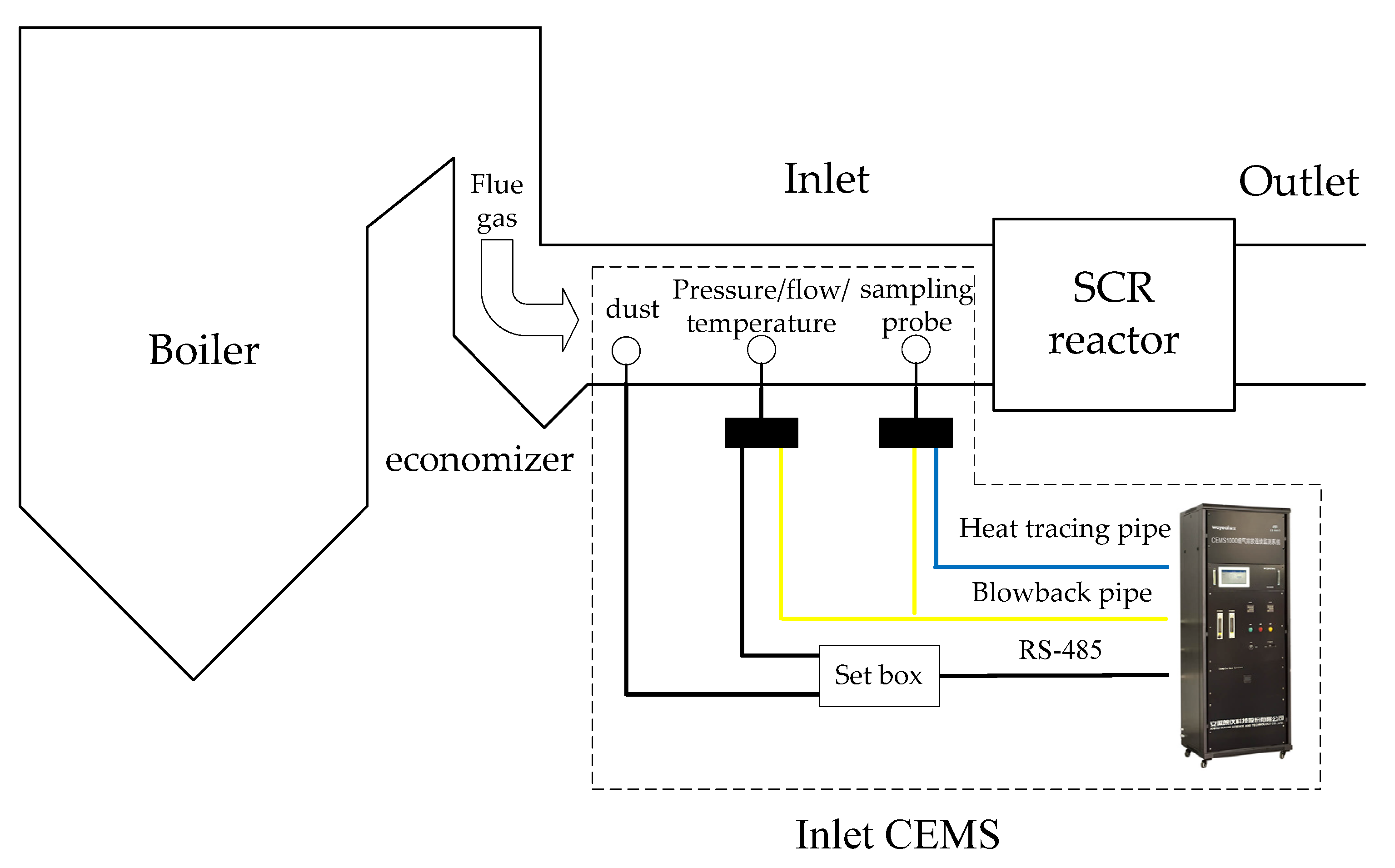
x analyzer in a continuous emission monitoring system (CEMS). The response lag of the inlet NO
x analyzer leads to the NH
3 injection valve action slowly. So, the SCR control system cannot eliminate the lag which undoubtedly increases the difficulty of the NH
3 injection flowrate control and causes the outlet NO
x fluctuation [
4,
5]. Therefore, by studying the data-driven model of the inlet NO
x concentration, the effect of lag on the SCR system can be compensated to some extent.
Some scholars proposed data-driven techniques to build prediction models based on the field data. Shakil et al. [
6] established the dynamic neural network (NN) model of the inlet NO
x concentration and inlet O
2 content in the SCR system, and principal component analysis (PCA) is then used to reduce the dimensionality of the input matrix, estimate the lag time by genetic algorithm (GA) algorithm, and finally validate the NN model by field data. Hsieh et al. [
7] proposed the data-driven model of the NO
x concentration based on Kalman filtering and the data fusion technique to overcome the lag time of the SCR system, but the method only used a lag time within 200 s. Peng et al. [
8] proposed PCA and SVR models to make more accurate and rapid forecasting of the inlet NO
x concentration, respectively. Lv et al. [
9] used a model combining an internal LSSVM model with an external linear PLS to predict the outlet NO
x concentrations. Li et al. [
10] proposed a modelling approach which combines the moving window partial least squares (MWPLS) and partially weighted regression to predict the outlet NO
x. However, the above method can only predict the inlet NO
x concentration at the current moment. Ahmed et al. [
11] used a real-time update strategy based on LSSVM to predict the NO
x, and it enhanced the long-term prediction accuracy. However, the model has some deviation when the boiler is under variable operation conditions. Yang et al. [
12] proposed a real-time dynamic prediction model of the inlet NO
x concentration based on LSSVM and considered delay time and prediction error. Xie et al. [
13] proposed a sequence-to-sequence dynamic prediction model to predict the future outlet NO
x concentrations. In addition, some scholars analyzed the effect of the inlet NO
x concentration measurement lag on the control effect by predicting the inlet NO
x concentration in advance. Matsumura et al. [
14] eliminated the effect of lag time to some extent by predicting the inlet NO
x concentration in advance with LSSVM, which improved the control accuracy and reduced the operation cost. Kříž et al. [
15] estimated the time delay by using the Lyapunov exponent and embedding dimension. Kang et al. [
16] proposed a bidirectional long- and short-term memory (LSTM) neural network and estimated the lag time of SCR systems by dynamic joint mutual information (MI). Song et al. [
17] used an improved MI feature selection algorithm to filter out the input variables of the inlet NO
x concentration model. The input variables are then fed together into the LSTM neural network to build the model. Liu et al. [
18] selected 22 key variables of the power plant and built the multiple linear regression (LR) model with three hidden layers. Wu et al. [
19] proposed the least absolute shrinkage and selection operator to select input variables and used long short-term memory to establish the model. Yuan et al. [
20] combined PCA and SGEM method to build an inlet NO
x concentration model. The MI method was used to select the input variables of the inlet NO
x concentration model. Li et al. [
21] built the mechanism models of the SO
2, inlet NO
x concentration and O
2 content, respectively. Then, the improved RBF neural network was then adopted to compensate the prediction error.
Table 1 shows the advantages and disadvantages of different data-driven techniques from different aspects in the literature [
6,
7,
8,
9,
10,
11,
12,
13,
14,
15,
16,
17,
18,
19,
20,
21]. The shortcomings of the existing literature are mainly the following two aspects: First, there is a lack of clarity in the analysis of the CEMS measurement lag. Second, there is a lack of quantitative conclusions.
Therefore, in order to improve the control effect of the NH3 injection flowrate, this paper proposes to improve the existing feedforward control strategy. Firstly, quantitative analysis is adopted to estimate the lag time, and it improves feedforward (IF) control by establishing an improved exponential prediction model for the inlet NOx concentration and using the output of this model as a feedforward signal. Secondly, in order to further improve the control accuracy of the PID control, an IF-PID control is proposed. Finally, the PID and IF-PID control are compared.
3. Data-Driven Model of the Inlet NOx Concentration
To implement the data-driven model of the inlet NOx concentration, it is necessary to first analyze the main influencing factors of the inlet NOx concentration and determine the input variables of the inlet NOx concentration prediction model. In addition, data pre-processing should be carried out, which includes dynamic correction of abnormal data points, online filtering and pre-processing of the blowback process.
3.1. Input Variables
The inlet NOx concentration is mainly related to the boiler combustion process, and the main factors of the process are obtained by analyzing the relevant factors of the boiler combustion process. According to the analysis of thermal NOx and fuel-based NOx generation process, NOx generation is mainly influenced by the following factors. In addition, the combustion zone temperature and O2 content are both related to NOx generation.
(1) When the power plant is put into automatic gain control (AGC), the load will fluctuate continuously, which will directly affect the total coal feed rate and total air volume. Since the total coal feed rate and total air volume changes are not synchronized, the air–coal ratio changes, thus affecting the variation of O2 content and leading to the fluctuation of the inlet NOx concentration.
(2) When the opening of combustion air baffle changes, it will also lead to unbalanced air combustion classification, and it will cause changes for the temperature field and O2 content distribution in the combustion area, which in turn leads to the variations of the inlet NOx concentration.
(3) The start and stop of the coal mill also affect the boiler combustion process, and causes the air–coal ratio to change, thus causing the O2 content in the boiler to change, which in turn causes the inlet NOx concentration to fluctuate.
According to the field data, the input variable data for the inlet NO
x concentration data-driven model were determined as shown in
Table 2. Since the data from the boiler are obtained earlier than the data from the SCR system, the model can be built by the variable data from the boiler side to predict the inlet NO
x concentration in advance.
3.2. Data Pre-Processing of Blowback Process
This paper adopts the method of linear interpolation to preprocess the inlet NO
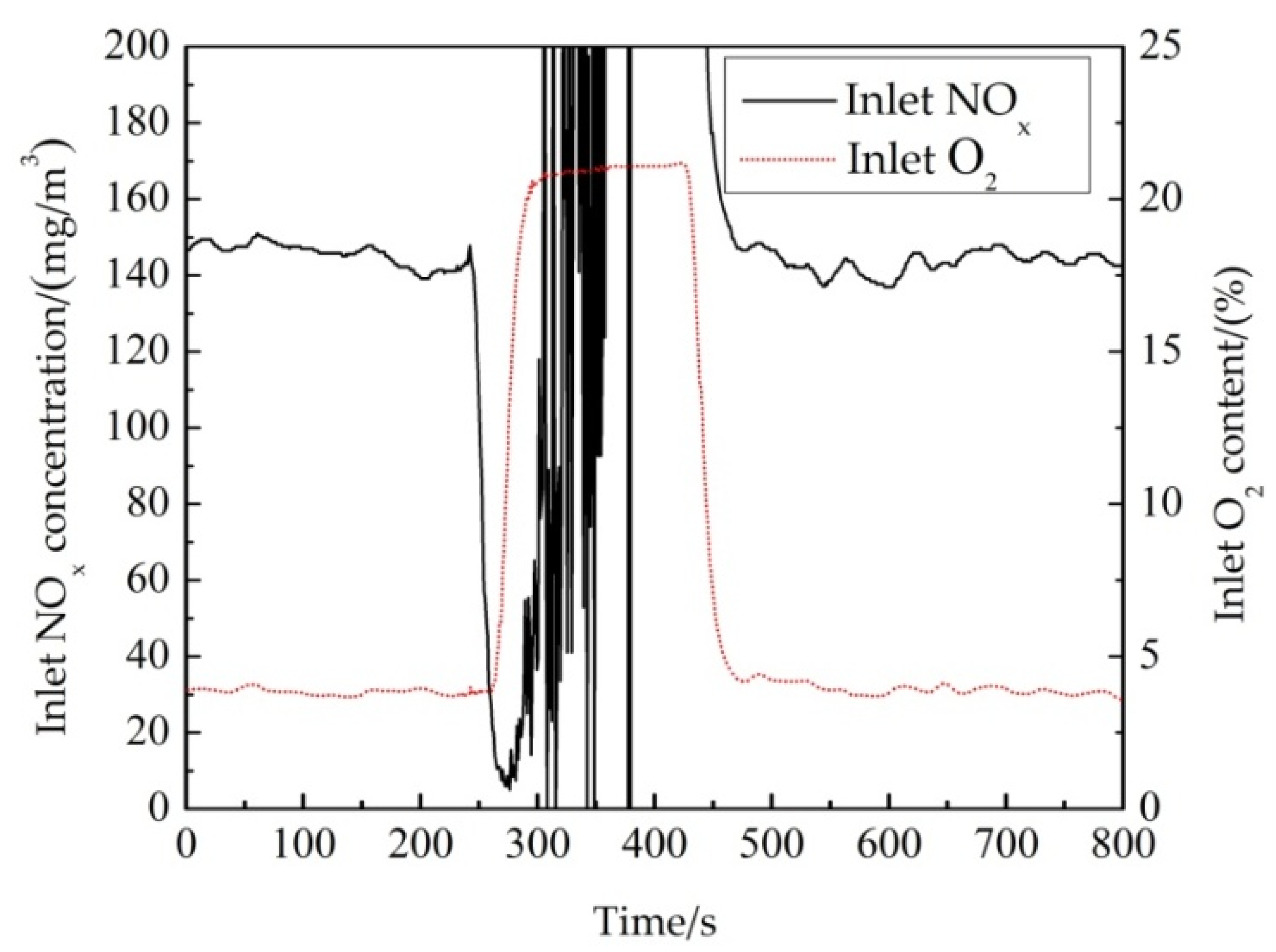
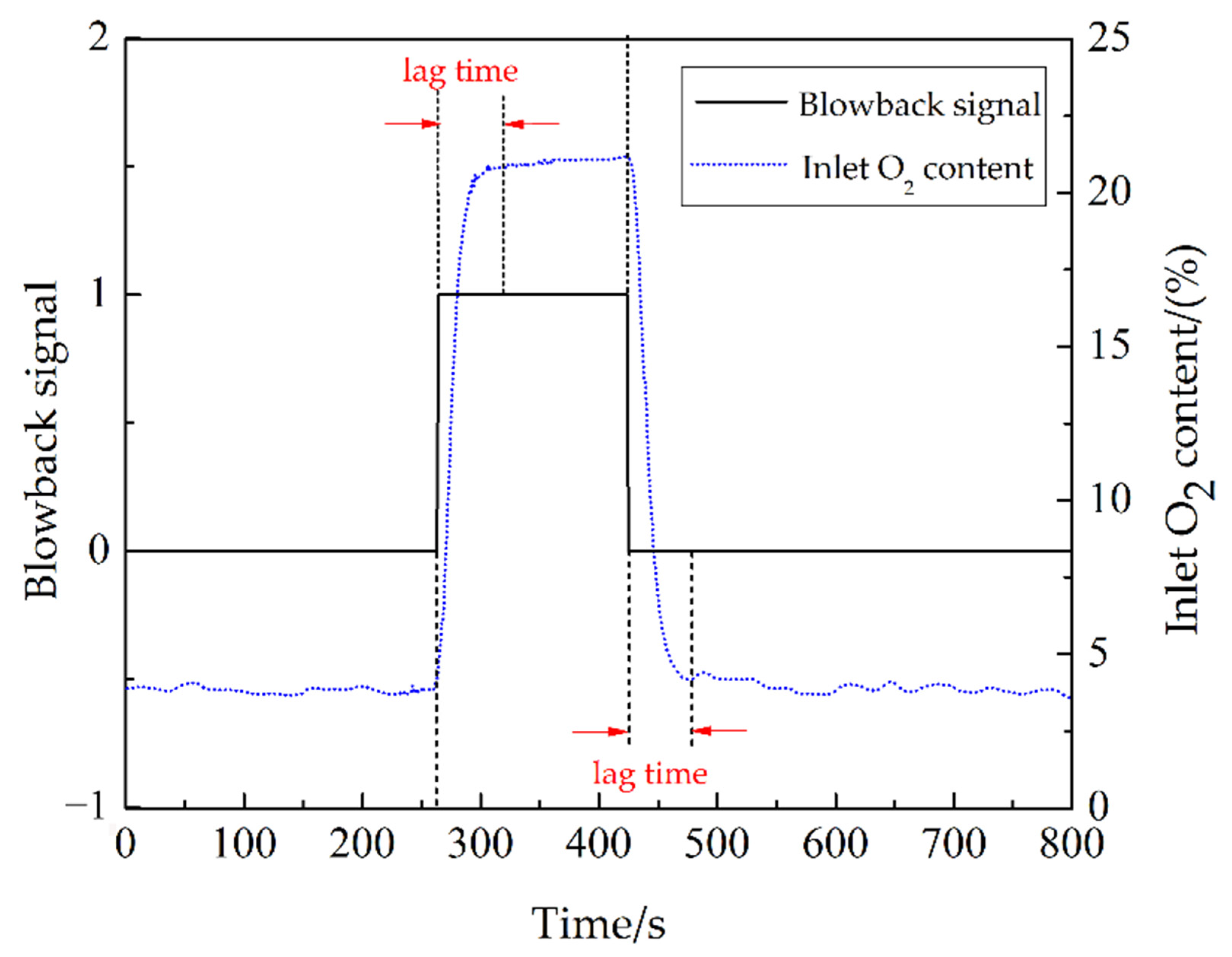
x concentration signal for the CEMS blowback process, because the signal of the CEMS blowdown has periodicity. According to the analysis of field data, the CEMS will execute a continuous 3 min blowback at about 4 h intervals. Because there are still some abnormal data points after the end of blowback process, the data preprocessing needs to increase the data of the blowback time. In this paper, the data of the inlet NO
x concentration is measured for a period of 1 s. For example, data preprocessing uses 280 data every 14,300 data by Equation (1).
Here,
is the inlet NO
x concentration at time t after preprocessing, m is the number of purge data processing points,
is the inlet NO
x concentration at the start of blowback process, and
is the inlet NO
x concentration at the end of blowback process. The pre-processed results of the inlet NO
x concentration during the CEMS blowback process are shown in
Figure 4. It can be seen from
Figure 4 that all abnormal data points during the blowback process are eliminated.
3.3. Data-Driven Model of the Inlet NOx Concentration
The data-driven model of the inlet NO
x concentration in many studies [
1,
2,
3,
4,
5,
6,
7,
8,
9,
10] is mainly one which only predicts the inlet NO
x concentration in advance for the current time and uses times series data to validate the model. There are two main drawbacks. One is that the predicted values are affected by the mean and standard deviation of the training set. So, it is impossible to track the curve changes in time when the inlet NO
x concentration fluctuates drastically. The other one is that the model parameter search is generally computationally time consuming. So, it is impossible to predict the inlet NO
x concentration in multiple steps in advance, which is contradictory to the purpose of the inlet NO
x concentration for a feedforward signal.
The exponential prediction can predict the inlet NO
x concentration, which can predict the true value in advance for a longer period of time [
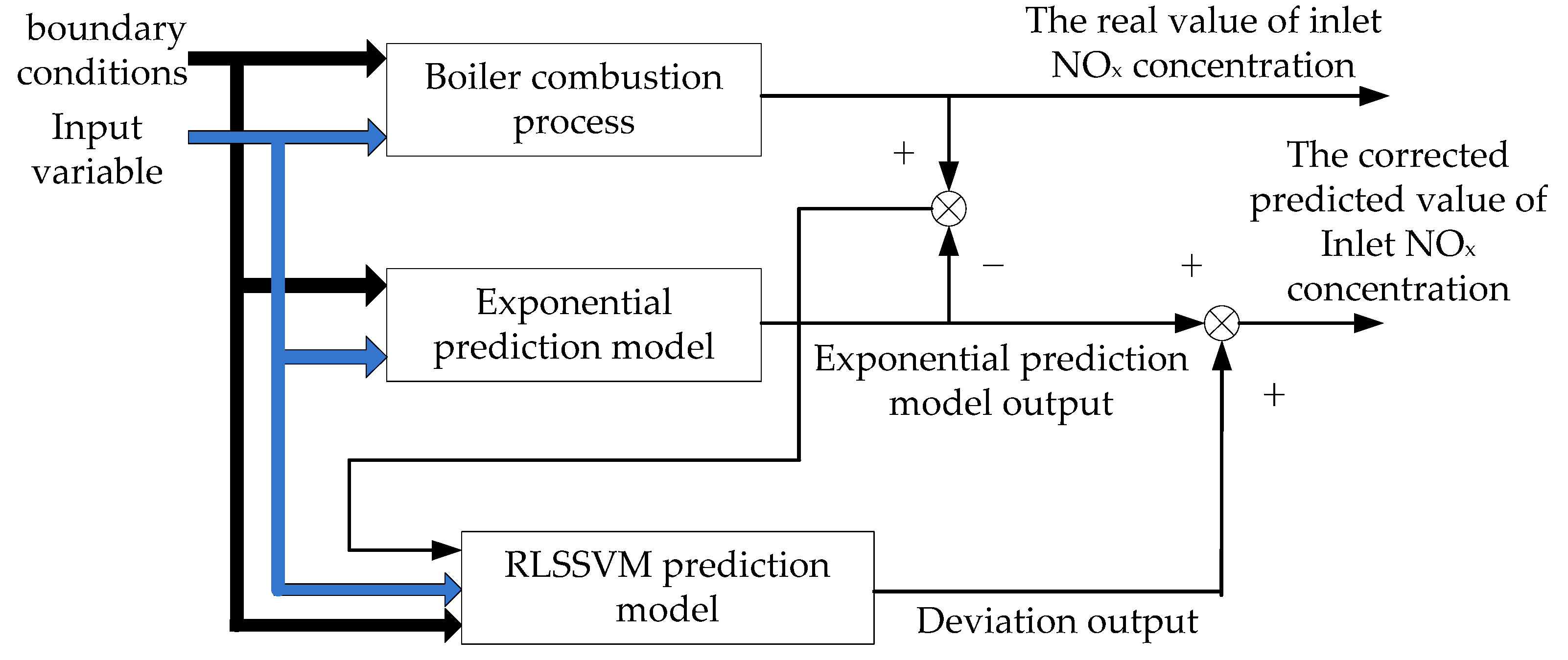
22]. In order to compensate for the output bias of the exponential prediction model, this paper proposes an improved exponential prediction model. The schematic diagram is shown in
Figure 5.
First, the predicted inlet NO
x concentration at time
t is obtained based on the exponential prediction model at time
t-
L, and then, the deviation between the predicted value and the measured inlet NO
x concentration at time
t is obtained. The deviation prediction model is established by RLSSVM. The model predicts the future
L-step deviations between the values of the exponential prediction model output and the real values of the inlet NO
x concentration, as shown in Equation (2). The output value of the RLSSVM model adds the output value of the exponential prediction model to achieve the purpose of correcting the exponential prediction model output.
Here, u represents the input variable of the exponential prediction model. represents the deviation between the real value of the inlet NOx concentration at step t and the predicted inlet NOx concentration by the exponential prediction model.
3.3.1. Exponential Prediction Model
According to
Table 1, the input variables of improved exponential model were determined. A numerical model established the exponential prediction model of the inlet NO
x concentration. The equation is as follows.
Here, W1 is the total air volume, W2 is the average opening of secondary air register, W3 is the boiler load, W4 is the air–coal ratio, and W5 is the O2 content of flue gas in the boiler outlet. Each of the above parameters is determined by non-linear fitting experiments, and the parameters are adjusted according to the operational condition of the boiler and the SCR system.
3.3.2. Recursive LSSVM (RLSSVM) Model
- (1)
LSSVM Model
Suykens et al. [
23] proposes LSSVM by improving the quadratic optimization problem of SVM. LSSVM uses the least squares method to transform the SVM learning into solving the problem of linear equation. So LSSVM reduces the computational complexity and has a better prediction accuracy.
Let the training set
,
is the input sample point, and
is the output sample point corresponding to
, then the SVM problem is represented by a simple transformation as
A Lagrangian function is established to turn the constrained optimization formula into an unconstrained optimization formula.
The KKT condition, then, is
After eliminating
and
, Equation (7) can be rewritten as
According to Equation (10), it can be seen that the training problem of LSSVM boils down to a solution problem of linear equations, so the training speed of LSSVM is faster than the training speed of SVM. The solution for
and
b are as follows.
The LSSVM model is obtained as Equation (13). The kernel function uses the radial basis function.
- (2)
RLSSVM Model
Assume the kernel matrix at time
t is as follows [
24].
, so
At time t + 1, a new sample is obtained. Similarly
At time
t + 1,
can be written as a block matrix as follows
Here, .
Equations (11) and (12) involve the inverse of kernel matrix, so
Here, .
Equation (18) shows that the can be obtained recursively from the at the previous moment and the newly added sample .
3.4. Simulation Experiment
The prediction model of the inlet NO
x concentration is developed. The simulation data come from field data from an operation condition near 800 MW. The parameters of the exponential prediction model were finally determined by optimization algorithm, as showed in
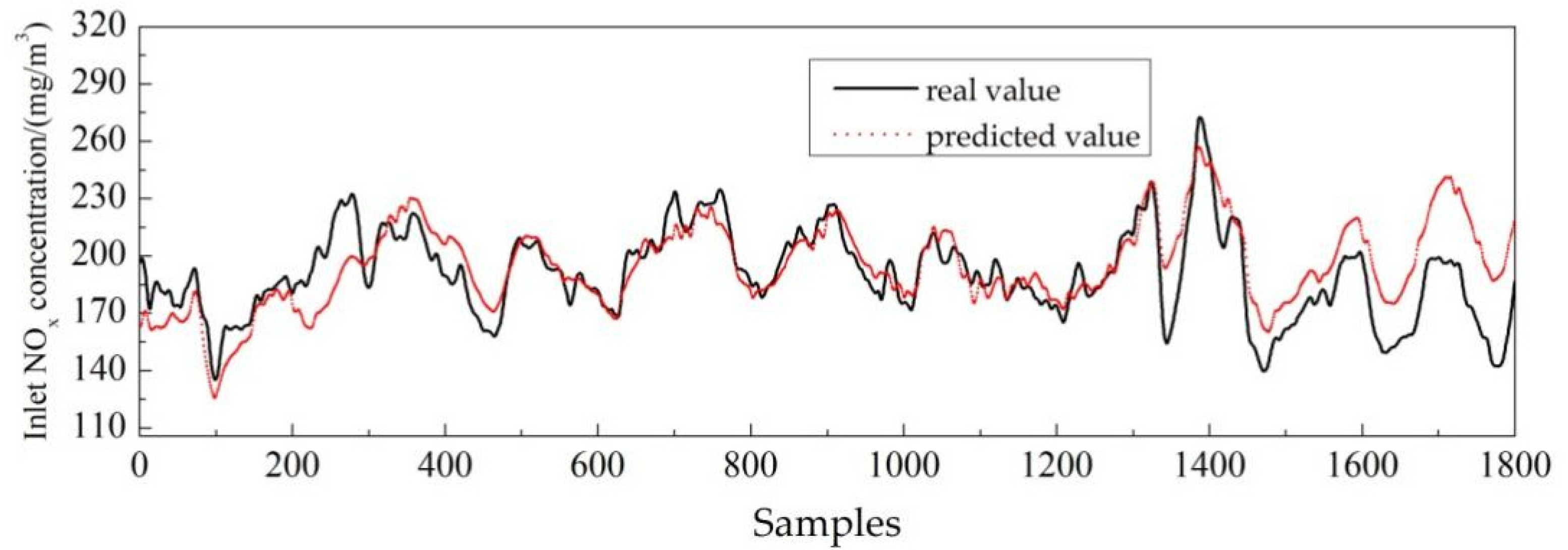
Table 3. For the exponential prediction model, the comparison of the predicted values and real values are shown in
Figure 6.
Figure 6 shows that from point 500 to point 1300, the boiler is in steady-state operation condition. So, the predicted values from the exponential prediction model are relatively well fitted with the real values, and the root mean square error (RMSE) value is 6.8990 mg/m
3. However, from point 200 to 300, the inlet NO
x concentration increases as increased total air volume, and the lag time of the NO
x analyzer can be estimated at 100 s or so based on the time difference between the rising curves of the predicted and real values. From point 1300, the predicted values and real values of the inlet NO
x concentration show a large deviation due to the increase in load from 800 MW to 900 MW. The predicted value is higher than the real value, and the RMSE value is 26.7963 mg/m
3. In all, the exponential prediction model can track the curve change when the inlet NO
x concentration changes significantly, but the disadvantage is that the predicted values from the exponential prediction model have some deviation from the real values when the boiler is exposed to variable operational working conditions. If the prediction value of the exponential prediction model under variable operating conditions is higher than the real value, it is easy to cause the SCR system to over-regulate the amount of NH
3 injection and cause NH
3 slip, so the amount of feedforward control usually adopts the speed limit and amplitude limit measures. On the one hand, the time delay of the model can be set at 60 s. On the other hand, the RLSSVM is used to predict the output deviation of the exponential prediction model and correct the output deviation. Taking the 600th to 1800th points of the inlet NO
x concentration as an example, the prediction curves of output deviation of exponential prediction model are shown in
Figure 7.
According to
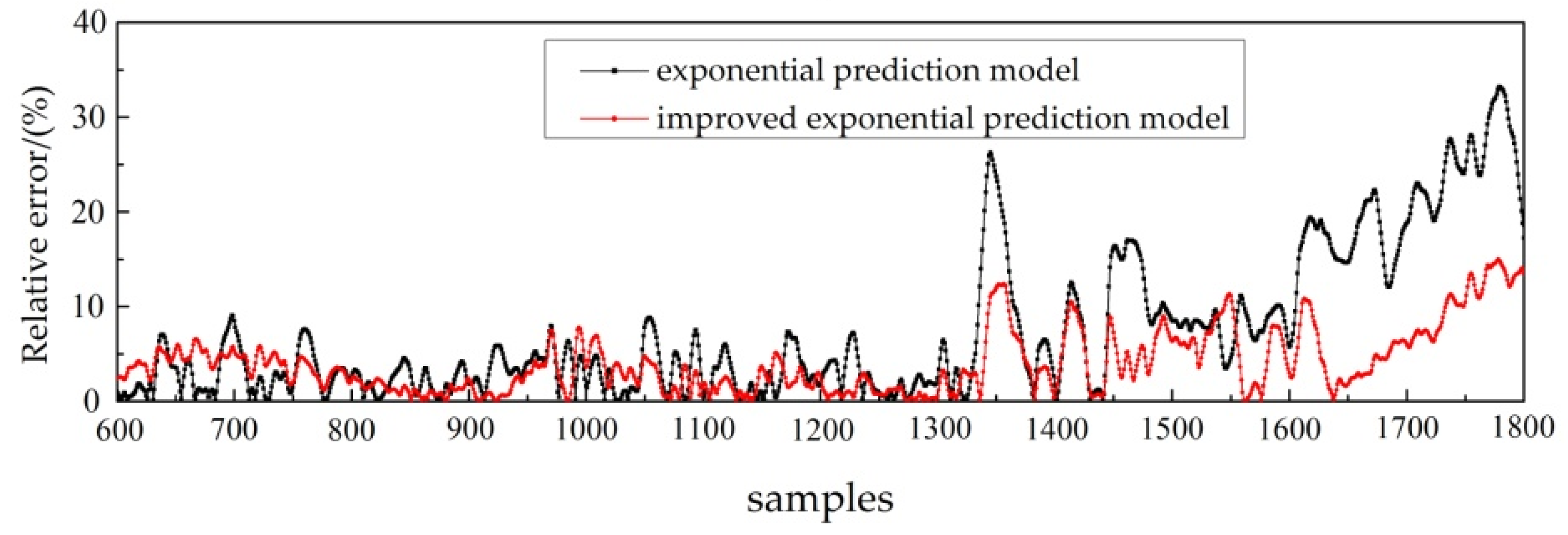
Figure 7, the exponential prediction model output deviation can be predicted 60 s in advance with a high prediction accuracy by using the improved exponential prediction model, which indicates that the deviation value is corrected in real time by using the RLSSVM model, and the trend change in the deviation prediction curve is basically consistent with the real value. Then, the relative errors and the comparative results between the improved exponential prediction model and exponential prediction model are shown in
Figure 8.
Figure 8 shows that the relative errors of two models are small before the 1300th point, when the boiler is under steady-state conditions. From the 1300th point, the relative errors of the two prediction models increase, but the relative errors of the improved exponential prediction model are smaller compared with the exponential prediction model. The experiment results show that the improved exponential prediction model can make the predicted values of the inlet NO
x concentration under variable working conditions closer to the real values of the inlet NO
x concentration, thus effectively avoiding the problem of high predicted value when using an exponential prediction model and, to a certain extent, avoiding the phenomenon of excessive NH
3 injection when using the exponential prediction model output as the feedforward signal.
4. Improved Feedforward Control Based on the Data-Driven Model of the Inlet NOx Concentration
For a NH
3 injection control system, the inlet NO
x content is obtained by multiplying the inlet flue gas flow and the inlet NO
x concentration, and it is often introduced in the control logic as a feedforward signal to achieve feedforward control [
25]. In order to quickly respond to the condition changes on the perturbation of the inlet NO
x concentration under different operation conditions, the lag time of the SCR reaction and flue gas analysis can be compensated to a certain extent. However, the feedforward control method is not ideal because of the response lag of the NO
x analyzer in the SCR system. So, this section achieves the goal of improving the feedforward control by predicting the inlet NO
x concentration in advance and using it as a feedforward signal.
4.1. Control System Structure
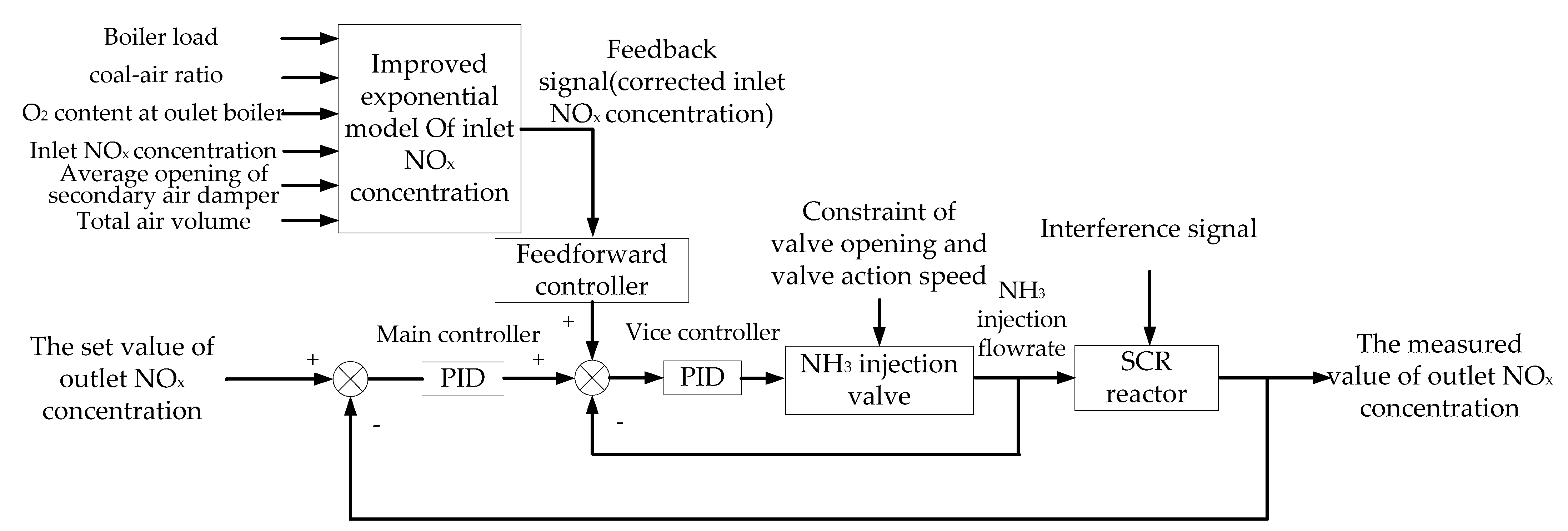
To further improve the PID control effect, the improved exponential prediction model output of the inlet NO
x concentration is used as a feedforward signal to improve feedforward control. The block diagram of an NH
3 injection composite control system based on an improved feedforward control and PID control is detailed in
Figure 9.
In
Figure 9, the real-time predicted value of the improved exponential prediction model output is used as the feedforward signal, and the NH
3 injection valve opening variation
is used as the feedforward control parameter.
is converted from the improved exponential prediction model output by the following equation.
Here, is the change in the inlet NOx concentration after improving feedforward control, mg/m3. That is the difference between the improved exponential prediction model output and the measured inlet NOx concentration at the current moment t. is the inlet flue gas flow rate, m3/h. and are the molar masses of NH3 and NOx. is the SCR de-NOx efficiency, %. is the variation of NH3 injection flow after adding feedforward control, kg/h. k is the linear coefficient between the variation of NH3 injection flow and the variation of NH3 injection valve opening. In general, NH3 supply pressure remains unchanged, so the intermediate distance between the NH3 injection valve opening and closing is a linear relationship. In this paper, according to the samples of the NH3 injection flow and NH3 injection valve opening, k = 3.82744.
The feedforward signal of the inlet NOx concentration can be predicted 60 s in advance and then through the feedforward control, so the PID controller can realize the early action of NH3 injection valve to control the amount of NH3 injection and adapt to the change in operation conditions.
4.2. Simulation Experiment
Before studying the control strategy for NH3 injection, this section analyzes the effect of the inlet NOx concentration measurement lag on the control system and the analysis of the control effect with the improved feedforward control.
First, the lag of the inlet NO
x analyzer on the control system is analyzed, and then the absolute error between the measured values and the real values of inlet NO
x are analyzed based on the lag time determined in
Section 2.2, as shown in
Figure 10.
Figure 10 shows that there are deviations between the measured and real inlet NO
x to the influence of lag. The deviations are much bigger when the inlet NO
x concentration fluctuates drastically. The absolute error reaches up to 73 mg/m
3. Therefore, in order to ensure the effect of the NH
3 injection control, the lag influence of the inlet NO
x analyzer on the control system must be considered.
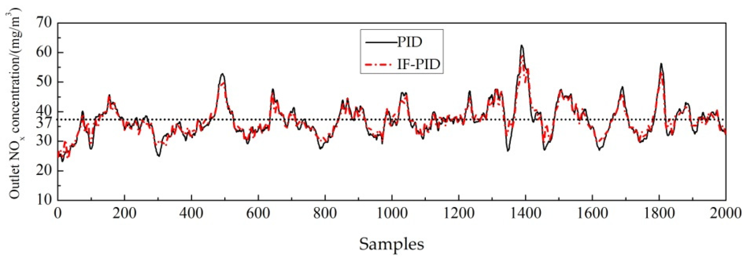
The control effect of the composite control based on the improved feedforward (IF) control and PID control (IF-PID), and the PID control is compared with: the IF-PID control on the outlet NO
x concentration, as shown in
Figure 11; the NH
3 injection flow rate, as shown in
Figure 12; and the optimization index, as shown in
Table 4.
According to
Figure 11, the measured values of the inlet NO
x concentration deviate significantly from the real values of the inlet NO
x concentration. It can be seen that the improved feedforward control can make the NH
3 injection valve operate earlier at the peaks and troughs of the outlet NO
x curve. Compared with the feedforward control, the outlet NO
x concentration converges to the set value of 37 mg/m
3. It indicates that the HP-PID control can reduce the excessive NH
3 injection and the NH
3 slip to a certain extent. On the one hand, the cost of NH
3 injection is reduced, and sustainable development of the enterprise is achieved; on the other hand, NH
3 slip is reduced, so air pollution is avoided, and environmental sustainability is achieved.
According to the optimization index results in
Table 4, the average outlet NO
x concentration is slightly reduced, the standard deviation of the outlet NO
x concentration decreases 20% (most outlet NO
x concentration points meet the national environmental protection regulation), the average de-NO
x efficiency remains the same, and the average NH
3 injection flowrate and average NH
3 slip are slightly reduced. It indicates that the inlet NO
x data-driven model based on the exponential prediction model and the RLSSVM can accurately predict the inlet NO
x concentration in advance, and the NH
3 injection control effect can be improved by improving the feedforward control.
Figure 12 shows that the IF-PID control further increases the NH
3 injection flow rate from point 1300 to point 1500 compared with the PID control, which reduces the outlet NO
x concentration but exceeds the maximum value of the NH
3 injection flow rate when the PID control is used. According to the analysis of the field data, the NH
3 injection valve opening reaches 50% at the 1300th to 1500th points using PID control, indicating that the actuator of the NH
3 injection valve has reached saturation at this time when an automatic control is used. Therefore, the outlet NO
x concentration is too high through the IF-PID control. The amount of NH
3 injection appears to overshoot. In field, if the actuator saturates during automatic control, the control effect will be adversely affected.
In addition, the feedforward control can make the NH3 injection valve act in advance according to the change in the inlet NOx concentration data-driven model. However, to some extent, the response lag of the PID control is due to the lag in the feedback signal of the outlet NOx concentration. Because the CEMS is installed at the outlet of the SCR reactor, the measurement lag of outlet NOx should not be neglected.





_Xu.png)


