1. Introduction
As common energy storage elements, hydraulic accumulators are often used in systems for energy recovery. The airbag-type hydraulic accumulator is often used as an energy storage device in hydraulic hybrid systems to recover the energy generated when a car is braked and supply power when the car is restarted [
1]. Studies have shown that when hydraulic hybrid technology has been applied to vehicles, fuel savings of 12–25% can be achieved in urban areas and fuel savings of 6–10% can be achieved during long-distance driving [
2,
3]. However, because the airbag type hydraulic accumulator cannot store and release energy at a constant pressure, the energy is often not fully recovered and is released due to the mismatch with the system pressure during the working process, resulting in energy waste [
4]. Although the airbag accumulator is used as an auxiliary energy source and its power density meets usage requirements, the volume energy density and weight energy density are obviously not enough [
5], which makes it difficult to apply hydraulic hybrid technology to small cars.
Many scholars have conducted research on hydraulic hybrid power systems and energy-storage element accumulators. Qingyong Zhang [
6] conducted theoretical analysis on the airbag type hydraulic energy storage of hydraulically driven hybrid vehicles. The results showed that under the same initial braking pressure, the pressure growth rate and pressure variation range in the chamber were smaller when the accumulator volume was larger. Under the requirement of vehicle braking performance, reducing the accumulator volume and charging pressure increases the specific energy of the energy storage element. Bo Wang et al. [
7] proposed a new configuration of a hydraulic hybrid electric vehicle based on compound accumulators. Simulation results showed that a hydraulic hybrid electric vehicle based on compound accumulators could switch the operation timing of large and small accumulators to take into account the energy recovery rate and braking performance. When the braking deceleration was 1.5 m/s
2, the energy recovery rate was 14.5% higher than that of a single accumulator. Eckert J [
8] proposed a comprehensive optimization procedure of a series electric hydraulic hybrid vehicle powertrain and control through the interactive adaptive-weight genetic algorithm method. Battery aging is effectively reduced by using a high power density hydraulic accumulator, which acts as a peak power buffer unit. Hyukjoon K [
9] introduced a thermodynamic theoretical method to analyze the energy characteristics of hydraulic hybrid systems. The method based on energy and exergy analysis is used in hydraulic hybrids.
Yunsong Lu [
5] showed that the use of two-phase media could stabilize the output pressure of the accumulator and increase the energy density of the accumulator by 3–5 times. The difficulty was that it was difficult for the saturated vapor pressure to meet the ideal requirements. Yunsong Lu raised a cylinder accumulator using a multi-layer structure of carbon fiber and high-strength metal. When the working pressure was 1 × 10
5 kPa, the energy density and specific energy were 1.05 × 10
2 kJ/m
3 and 14 Wh/kg, respectively, which were 10 and 20 times greater than those of existing rigid accumulators. However, this still did not solve the problem of constant-pressure energy storage and release, and the production cost was higher. Alexander P and Eric J. Barth [
10] put forward a hydraulic-strain-energy accumulator by using elastomer with a strain-energy-storage mechanism to obtain a higher energy storage efficiency and energy density. On this basis, John T. Tucker [
11] evaluated and verified the materials, built a pressure prototype (the maximum filled liquid pressure was 3.8 × 10
2 kPa), and found that the energy storage efficiency of polyurethane in the accumulator exceeded 88%. Daniel N. Cramer and Eric J. Bart [
12] conducted charging/discharging tests on rubber airbags of different materials and concluded that the latex airbag had ideal expansion and contraction behavior. They also determined the energy efficiency of the airbag with different inner diameters and materials. John M. Tucker and Eric J. Barth [
13] established a mathematical model of the energy density of a hydraulic strain energy accumulator, analyzed the factors that affected the energy density, and presented corresponding solutions. Joshua J. Cummins et al. [
14] established a mathematical model of the charging/ discharging energy storage efficiency of pneumatic strain energy accumulators based on the enthalpy analysis method, and they explored the influence of the rubber Mullins effect on the expansion pressure, contraction pressure, and energy storage efficiency of the device.
From the above analysis, it is known that the expansion pressure of the strain energy accumulator based on rubber material is an effective energy storage device with high energy density and steady pressure output. The pressure is determined by the material, wall thickness, and radial expansion radius. However, two problems that the above studies did not consider require further focus. On the one hand, in order to adapt to different system pressures, it is necessary to customize the airbag. On the other hand, the device’s performance depends heavily on the rubber material characteristics. With the increase in the number of uses, the rubber material damage will increase, which will inevitably lead to a decline in the performance of the whole device.
The key to solving these two problems is to perform accurate energy analysis, which should be carried out simultaneously from the perspectives of energy quantity and quality. The common enthalpy energy analysis method only analyzes the energy storage efficiency from the perspective of the amount of energy, and it cannot reveal the qualitative changes in the energy during the conversion or transfer process. At the same time, the method cannot fully reflect the loss within the system [
15]. At present, an energy-saving analysis method widely used in industry is the exergy analysis method, which combines the “quantity” and “quality” of energy, scientifically analyzes the utilization of energy conversion and transmission, and truly reflects the external and internal losses in the process of energy utilization [
16]. Kaiser F. [
17] analyzed the optimized energy-saving scheme of an industrial compressed air system based on the combination of the exergy analysis method and the energy efficiency method. The results showed that the exergy analysis method was more in line with the actual situation and could be used to make more accurate decisions on the energy savings of compressed air systems. Chen L. [
18] used exergy analysis to study the performances of the main components of a single-stage adiabatic compressed air energy storage system under different working conditions.
In summary, the strain-energy accumulator based on the study by Joshua J. Cummins et al. [
14] was further investigated in this paper. One aspect that has not been studied is examined: accurate energy analysis to solve the problem of the energy loss inside the accumulator and the fatigue of the rubber airbag. Therefore, this paper mainly focuses on an accurate energy storage efficiency model and the influence of the Mullins effect during the process of rubber airbag charging/discharging by exergy analysis, and then built a test platform to verify the energy storage efficiency. First, the structure of the constant-pressure elastic-strain energy accumulator and the principle of constant pressure is explained. Then, the specific modeling process is given, and a constant-pressure elastic-strain energy accumulator charging/discharging test platform is built to verify the difference between the exergy analysis method and the enthalpy analysis method. Finally, combined with uncertainty analysis, the influence of the Mullins effect on the charging/discharging performance of the rubber airbag is explored.
2. Elastic-Strain Energy Accumulator Design
The structure of a constant-pressure strain-energy accumulator [
19,
20] is shown in
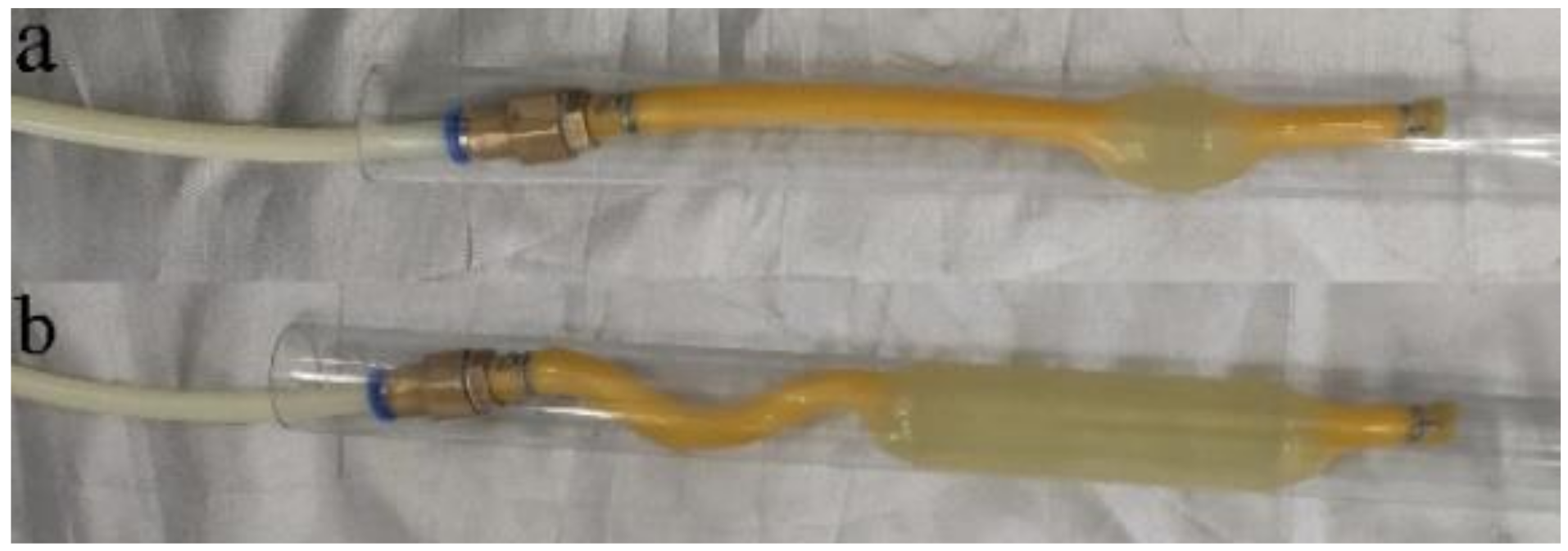
Figure 1, which is mainly composed of a rubber airbag, rigid shield, fixed ring, quick coupling, etc. The rubber airbag is used to store energy. Additionally, the principle is that when the airbag is charged with gas, the compressed gas performs work on the airbag so the airbag is expanded and the gas pressure energy can be converted into strain energy and stored in the elastic body. When the airbag contracts and performs work on the gas, the elastic body strain energy can be converted into pressure energy and released the stored energy. The rigid shield limited the rubber airbag radial strain. On the one hand, it could increase the pressure during the charging/discharging process; on the other hand, it could prevent the rubber airbag from reaching the ultimate strain every expanded time and causing premature fatigue to ensure the device performance. The fixing ring was connected with the rigid shield and the quick coupling by an interference fit, which limited the position of the rigid shield and the quick coupling.
The constant-pressure elastic-strain energy accumulator’s characteristic is that it can expand and contract at a relatively constant pressure when charging/discharging. The charging/discharging pressure-volume curve is shown in
Figure 2, and a typical rubber material stress–strain curve is shown in
Figure 3. It can be seen from the figure that the volume changes continuously during the process of charging and discharging, while the expansion pressure and contraction pressure remain relatively constant.
The stress–strain curve in
Figure 3 was divided into four regions. Region_(a), corresponds to the initial elastic modulus of the rubber, which corresponds to the gas pressure rise stage in
Figure 2. As more gas is filled in, the stress on the rubber airbag increases, and the elastic modulus begins to decrease, corresponding to region_(b) in
Figure 3. At this time, the rubber airbag undergoes hyperelastic deformation and begins to expand, resulting in a sudden increase in the airbag volume. The gas pressure decreases, as shown in
Figure 2. Subsequently, the pressure continues to decrease until the elastic modulus of the expansion zone of the rubber airbag increases, as shown in the region_(d), and the elastic modulus in this stage is the same as that in region_(a). The local increase in the elastic modulus is caused by the local strain hardening of the rubber material. At this time, the expansion area of the rubber airbag begins to move along the axial direction of the airbag with the minimum elastic modulus in region_(c). When the expansion area moves in the axial direction, the pressure is not changed, while the volume continues to increase, corresponding to the flat area in
Figure 2.
The energy loss during the charging/discharging process is mainly caused by three factors: (1) the rubber material’s mechanical properties (such as the Mullins effect, hysteresis effect, etc. which can cause material deterioration); (2) the friction between the airbag and rigid shield during the charging/discharging process, causing energy loss; (3) pressure loss due to thermal changes. The impact of these three factors on the rubber airbag is directly reflected in the value of its contraction pressure, which is lower than the expansion pressure and leads to energy loss. The relationship between the expansion and contraction pressure is very important to consider when analyzing the energy storage efficiency.
5. Steady-State Characteristic Analysis
The main indexes used to evaluate the constant-pressure elastic-strain energy accumulator quality was whether the expansion pressure, contraction pressure and energy storage efficiency can be maintained consistently during the charge/discharge cycles.
As an energy storage component, due to the Mullins effect and the hysteresis effect, the rubber airbag performance inevitably decreased during the charging/discharging cycles. The performance changes were affected by the changes in the expansion pressure, contraction pressure, and energy storage efficiency. Uncertainty analysis was performed to determine whether the airbag performance after multiple charging/discharging cycles met the use requirements.
The calculation of the average
μ, standard deviation
σ, and standard deviation of the mean value
SD μ during 40 cycles of each test is shown in Equations (9)–(11).
where
n is the total number of data points and
xi is the value of the
i-th data point. Due to the Mullins effect, the data obtained from the first charging/discharging cycle will be very different from the subsequent data. Therefore, the first charging/discharging cycle data in every period was discarded in the uncertainty analysis. The average value and standard deviation of each parameter in the charging/discharging cycle are shown in
Figure 16,
Figure 17 and
Figure 18.
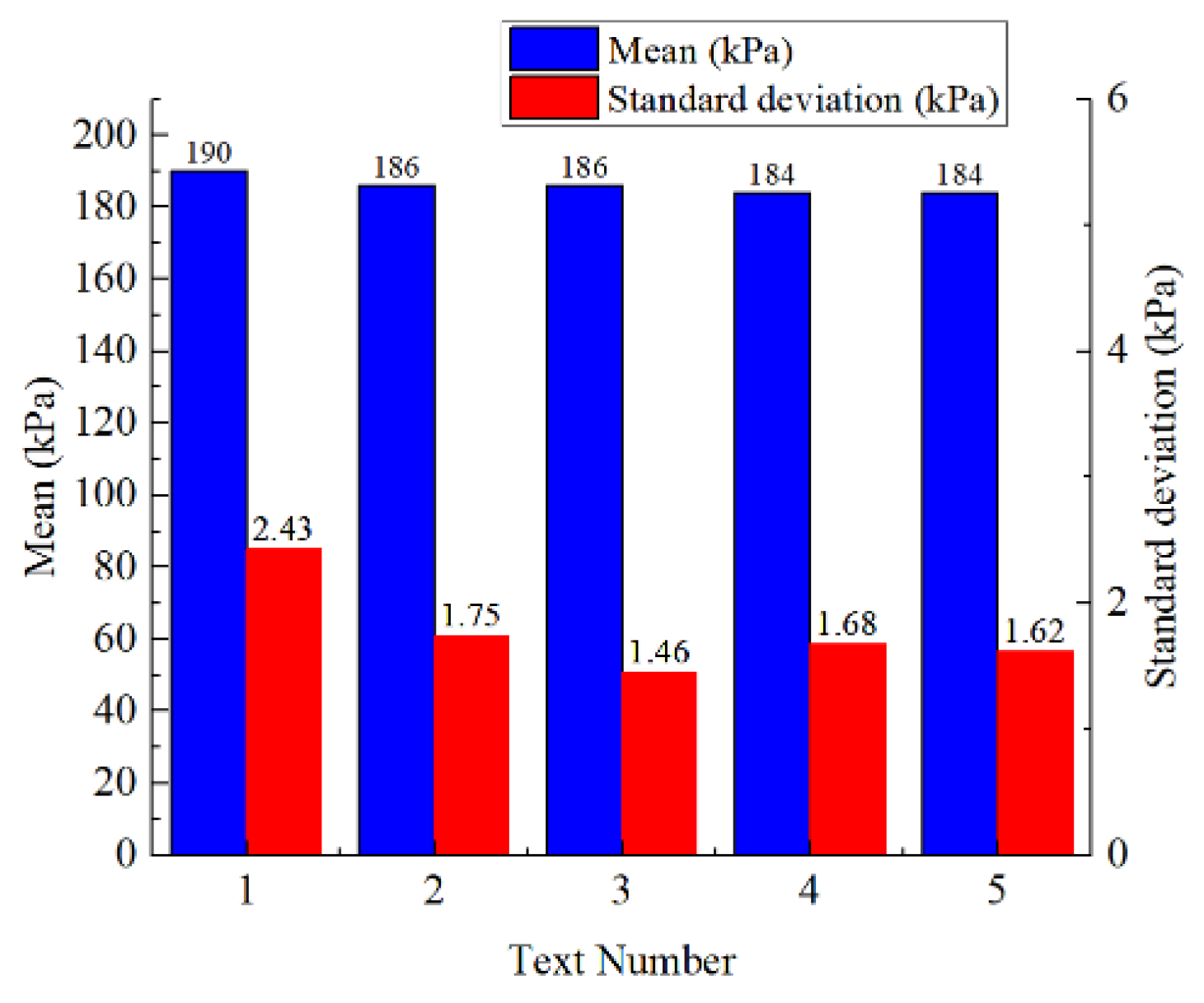
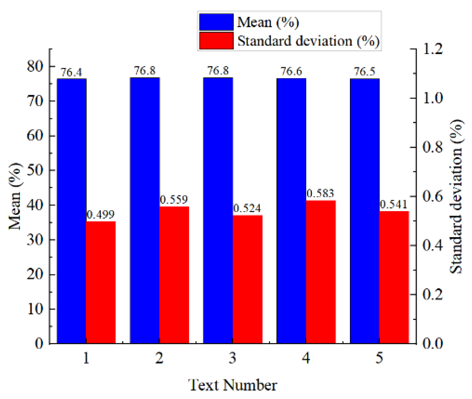
From
Figure 16 and
Figure 17, it can be seen that the expansion pressure average value decreased by 6 kPa and the contraction pressure average value decreased by 4 kPa in the five test periods, and the standard deviations were 2.92 kPa and 1.79 kPa, respectively. According to
Figure 18, it can be seen that the energy storage efficiency average value change in five test periods was 0.2%, and the standard deviation was 0.317%. The above data indicate that after multiple cycles, the rubber airbag still had good mechanical properties.
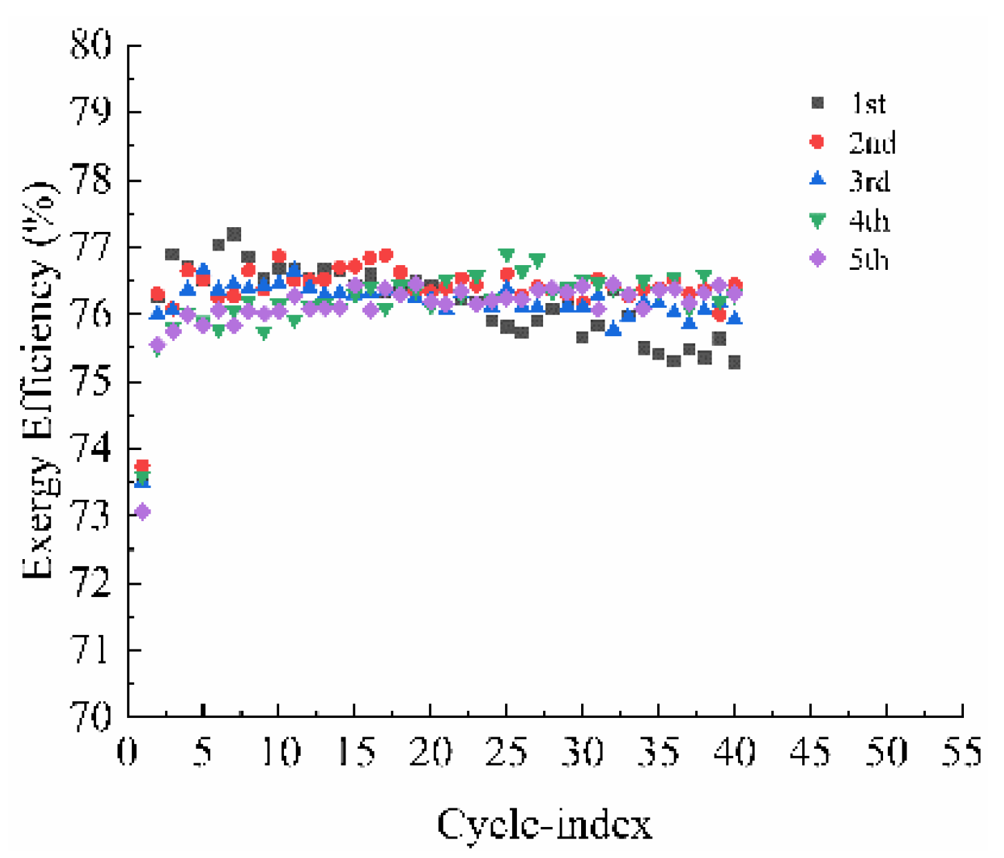
In previous work, the energy storage efficiency model was established based on the enthalpy analysis method, and the experimental analysis was conducted (the results are shown in
Figure 19). In 200 charging/discharging cycles, the energy storage efficiency error was 0.584%, and the average energy storage efficiency was 76.9%.
From
Figure 18 and
Figure 19, it can be seen that the standard deviation of the average energy storage efficiency calculated based on enthalpy analysis is 0.317%, and the standard deviation of the average energy storage efficiency calculated based on exergy analysis is 0.584%, which indicates that the accuracy of the energy storage efficiency calculated by exergy analysis is higher than that calculated by enthalpy analysis.
6. Conclusions
Aiming at the insufficient energy-storage efficiency modeling with the enthalpy analysis, this paper mainly focuses on establishing a rubber airbag charging/discharging energy storage efficiency model based on the exergy analysis method, studies the influence of the Mullins effect during the process of rubber airbag charging/discharging by exergy analysis, and builds a test platform to discuss the energy storage efficiency. The main conclusions are as follows:
(1) The experiments confirm that the error of the energy storage efficiency model based on the exergy analysis method is reduced by 0.267% compared with the enthalpy analysis method, which proves that the exergy analysis method is relatively accurate.
(2) The Mullins effect is mainly reflected in the expansion and contraction pressure changes during the charging and discharging cycles. The expansion pressure average value decreases by 6 kPa, and the contraction pressure average value decreases by 4 kPa. The corresponding standard deviations are 2.92 kPa and 1.79 kPa, respectively.
This paper verifies that a constant-pressure strain-energy accumulator can store and release energy at relatively constant pressure with high energy-storage efficiency. Future work will explore other structures, such as different sizes of the rigid shield and the rubber airbag, to maximize the energy storage efficiency and energy density. Ultimately, this will achieve the goal of meeting the needs of strain energy accumulators in medical rehabilitation equipment, stable gas sources, and other more extensive applications.


