Article

A Dynamic Road Network Model for Coupling Simulation of Highway Infrastructure Performance and Traffic State

1
College of Transportation Engineering, Tongji University, Shanghai 201804, China
2
Highway Monitoring and Response Center, Ministry of Transport, Beijing 100029, China
*
Author to whom correspondence should be addressed.
Sustainability 2022, 14(18), 11521; https://doi.org/10.3390/su141811521
Submission received: 25 July 2022 / Revised: 3 September 2022 / Accepted: 9 September 2022 / Published: 14 September 2022

Abstract

:
The state of the road network contains both the infrastructure performance and the traffic operation state of the road network. There is a strong coupling between the decay of the infrastructure performance and the redistribution of the traffic flow on the road network. In this paper, a dynamic road network description model is proposed to apply to the couple simulation of highway network infrastructure performance and traffic state. First, a road network description model is constructed by associating the highway network topology with state attributes. The topology contains traffic information and is dynamically editable. Then, a dynamic road network model is proposed that can dynamically represent the changes in local connectivity relationships caused by traffic control, such as lane/ramp closures and turning restrictions in actual roads due to construction operations and access to the state of multi-scale spatio-temporal road networks. It overcomes the defects of the existing road network model, which is difficult to apply to the analysis of service performance and traffic state of the road network in different periods. Finally, the application of the dynamic road network model in the highway network coupled simulation system (HNCS) is completed, which provides a method for improving the efficiency and accuracy of large-scale highway network traffic simulation and highway infrastructure performance prediction.

1. Introduction

With the development of traffic applications and computer technology, the study of road network models has evolved toward a more microscopic, large-scale, and realistic existing road network form. The two common basic modeling units are road centerline [1] and lane [2,3]. Hierarchical models [4] have been proposed for different tasks, as well as 3D road network models [5,6,7]. The centerline-based topology has the advantages of a simple structure and a clear network for easy analysis, but it cannot describe the topological relationships and lane-level attributes of the actual road network very precisely. The lane-based road network model, first proposed by Fohl et al. [8], can describe the traffic state and the actual topology of the traffic network in detail, but a large amount of data and the complexity of topology and network analysis are not conducive to large-scale network analysis, although it is beneficial for navigation. Li et al. [9] proposed a feature/integrated lane/lane-based model using classification and aggregation, which reduces data redundancy and improves the efficiency of network analysis compared with the traditional lane model but at the same time loses some lane attributes or increases the difficulty of data and processing. Levi Vermot et al. [10] designed a topology for analyzing freight road networks. The main idea is how to form a topology with minimal nodes and links. In conclusion, road network models, as the base models for applications such as intelligent transportation systems (ITS), in-vehicle route guidance systems (IVRG), traffic planning, and traffic network control, are used at different spatial scales for different tasks [4].
From the perspective of time, the road network model can be divided into static and dynamic models. Road network planning models are mostly static models, while ITS and IVRG are mostly dynamic models. There are also different interpretations of dynamic models under different tasks. For example, Li et al. [11] proposed a time-dependent road network model (TRNM) to represent these topological relationships and presented its construction method based on a traditional carriageway network model. Yumin Chen et al. [12] put forward a two-layer data structure consisting of a data storage layer and dynamic topology layer considering dynamic topology. The rapid dynamic topology construction method of the road network was put forward based on this two-layer structure, allowing the problem of road network dynamic topology construction to be solved. Yang et al. [13] presented a generalized urban road network model combining static and dynamic models, combining the basic ideas of object-oriented modeling and modular modeling, and abstracting the road network entities into a layer of independent hierarchical models based on hierarchical relationships. There are also some studies on dynamic road networks in traffic planning. For example, Gang Ren et al. [14] proposed the concept of dynamic road networks adapted to traffic planning, studied its characteristics, built a dynamic road network model based on the improved traditional road network model, and conducted an example analysis of the application of the model.
At present, most studies about the road network model focus on the urban road network, and a few studies on highway networks only aim at one kind of functional requirement. Yuren Chen et al. [15] proposed a highway network structure containing ramp information, which adopted a two-layer topology to improve the search speed of the road network. However, the model was highly simplified and lacked lane and direction information, which struggled to meet the accuracy of current traffic simulation applications. The highway network model proposed by Yingfei Qi et al. [16] focuses on the geometric characteristics of the highway, and the data are transitional and redundant, which is not conducive to the operation of large-scale road network data. In general, the research on the topology of the highway network is relatively simple in application, which cannot simultaneously describe the requirements of the evolution scale of the traffic state and the road infrastructure state of the road network.
The relationship between road infrastructure performance and road network traffic state interactions is reflected in many studies. On the one hand, road infrastructure performance affects vehicle travel speed and roadway capacity [17]. Through path selection, it affects the traffic volume distribution of the road network. On the other hand, traffic loads act and influence road infrastructure performance. For example, Chen et al. [18] developed an LDE model to predict rutting as a function of structural number (SN), load repetitions, and load intensity. Four test pavements had LDEs higher than 7.8, indicating a significant impact of loading on rutting performance. However, in the actual road network, there is a strong coupling relationship between road infrastructure performance and road network traffic state. First, the road facilities under the irregular use of load and environmental factors show significant differences in performance conditions and decay dynamics. Second, the variability of road facility decay further affects the distribution of traffic load on the road network. We hope to study the coupling mechanism of road infrastructure performance and road network traffic state by establishing a coupled simulation model. The dynamic road network model is the basis of the coupled simulation model, which can both dynamically update and store the traffic indexes and road facility service performance indexes needed for the coupled simulation at the same time.
The remainder of this paper is organized as follows. In Section 2, we propose a road network description model for the characteristics of highway network structure and realize the joint expression of the traffic topology and road network state. On this basis, we present the dynamic road network model in Section 3. The dynamic road network model consists of four parts: the basic road network, the traffic network, dynamic events and the state update program. The basic road network and the traffic network are based on the road network description model to store road network state data by topology associated with a multi-attribute sub-lane. Section 4 shows the application of the dynamic road network model in the coupled simulation system and analyzes the simulation results to verify the effectiveness of the dynamic road network. We make some concluding remarks in Section 5.

2. The Demand for the Dynamic Road Network Model

This section will specifically analyze the requirements of simulation tasks on the dynamic road network model. The state of the road networks includes both the service performance of road infrastructure and the traffic operation state, and there is a strong coupling between the decay of service performance of road infrastructure and the redistribution of traffic flow in the road network. Simulation technology can fully use computers’ high-speed computing ability to simulate the dynamic evolution of the road infrastructure state and the traffic operation state on the road network by constructing an appropriate simulation model based on existing measurement data. The dynamic road network model, as an important module of the coupling simulation model, needs to meet the following requirements:
First, the road network model should describe the actual situation of the road network as much as possible. Besides considering the topological relationship of traffic operation, it should also include the service performance state of road infrastructure.
Second, the spatial-temporal scale of the road network describing the state should meet the requirements of service performance decay prediction and traffic analysis accuracy at the same time. On this basis, the rationality and uniformity of the spatial-temporal scale should be considered to reduce the storage redundancy of data structure and carry out traffic network analysis efficiently.
Third, due to the influence of traffic control and the decay of the road infrastructure, the traffic connectivity of the road network changes with time and space. Therefore, the topology in the road network model needs to be dynamically editable.
In summary, the road network model, as the main module of the coupled simulation system, puts forward different requirements for unified expression and efficient access to the road network data. It is necessary to build a dynamic road network model that can both accurately express connectivity relationships and simultaneously meet the scale of service performance prediction of road infrastructure. Therefore, the road network model in this paper focuses on the abstraction of traffic connectivity relationships and the management of road lane data.

3. Road Network Description Model

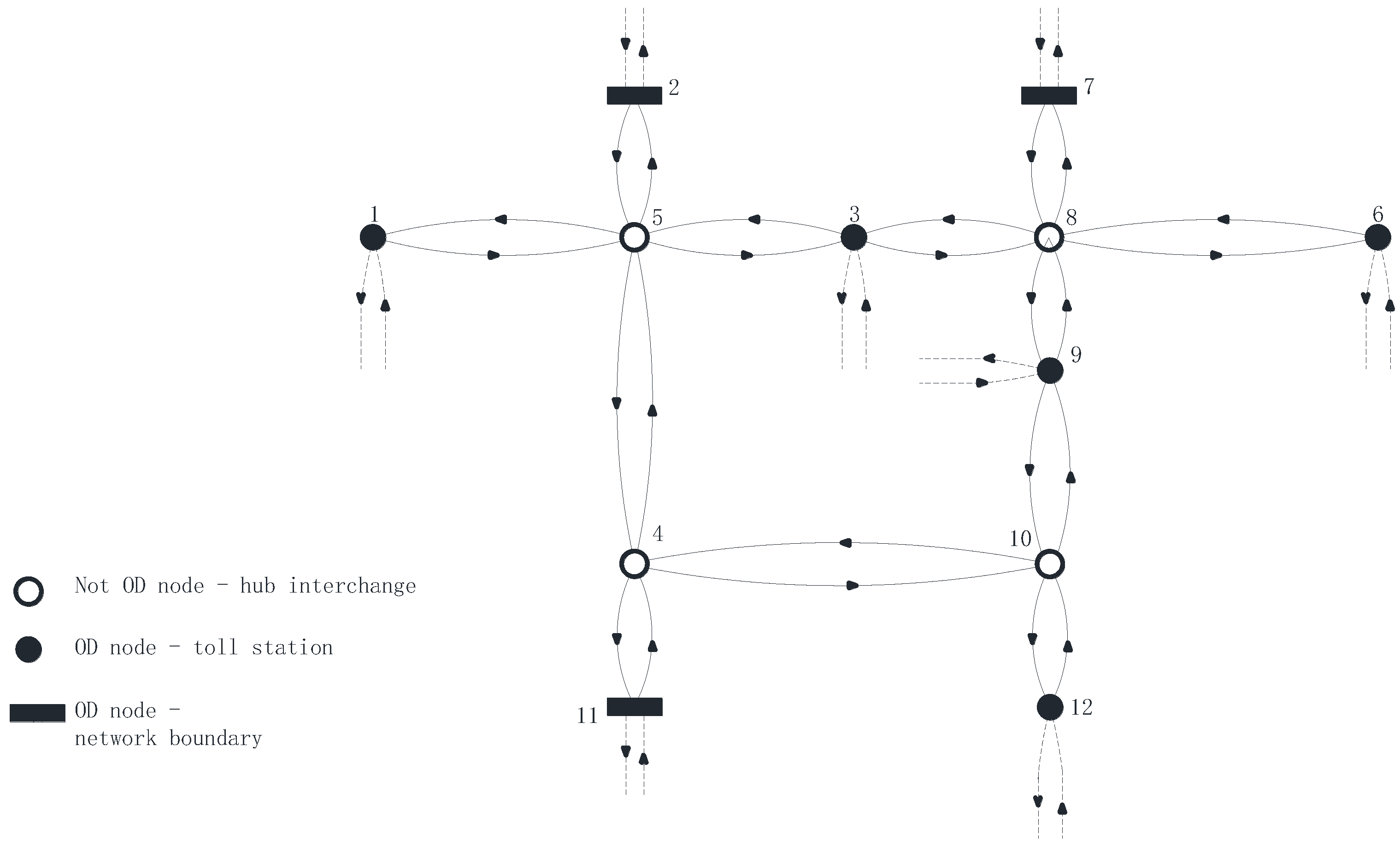
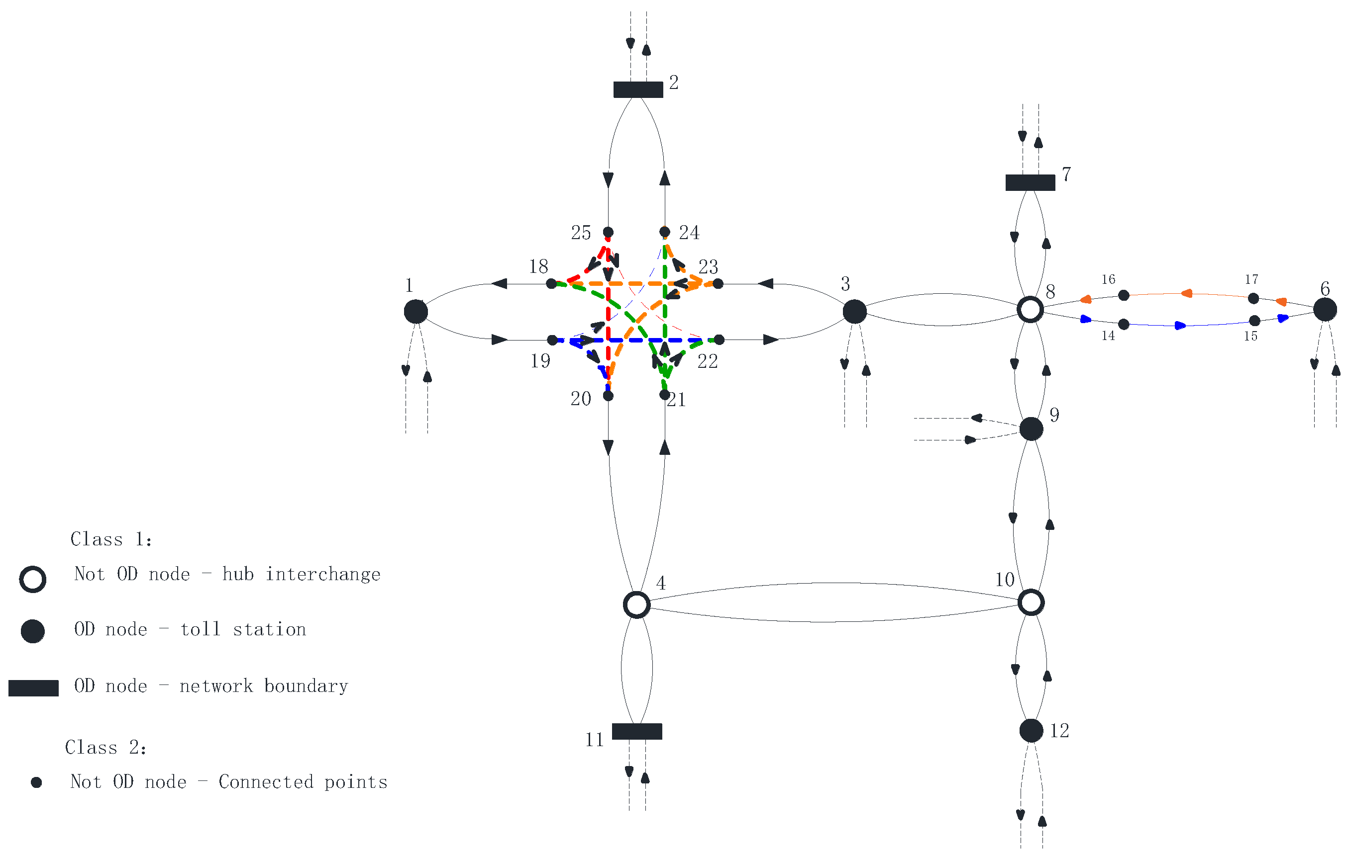
3.1. The Road Network Topology

Vehicles traveling along a fully closed, long, linear highway with no intersections can only drive in one direction. Based on the above characteristics, the directed graph is selected to represent the topology of the highway network. According to graph theory, the road network is represented by a directed and connected graph G = (Node, Edge), where Node is the set of nodes, and Edge is the set of directed arcs of connected nodes, namely the set of links. To express the local connectivity of the highway network more accurately, the topological representation is divided into two types: basic topology and extension topology. The basic topology takes OD points and interchanges them as nodes and links as basic modeling units to express the basic connectivity of the road network. The extension topology adopts the method of local extension one by one, with the connected point as the node and the link as the minimum modeling unit. The two types of topology jointly form the network topology.
Class 1:
Basic Topology
The basic topological relationship is a link-node centerline network. The link-node centerline network represents the connectivity between roadways with a set of links and nodes. Nodes represent locations along the centerline of a roadway where traffic starts, stops, or relays (e.g., OD points and interchanges). Links represent traffic flow connectivity between nodes. Figure 1 shows the basic topology of a simple road network.
Class 2:
Extension Topology
The extension topology is a supplement to the basic topology. The purpose is to more accurately describe the connectivity and the state of the road network. Firstly, the actual traffic network can be affected by traffic events, traffic control or construction operations. This manifests itself on the road network as a local closure of a main road, a closure of an on-ramp, etc. This connection information must be able to be set flexibly on the topology in order to more accurately describe the road network topology for dynamic evolution simulations. In addition, the actual road network is subject to traffic control (speed limit/load limit) and differential decay of component performance. These make the state of some components (bridges/tunnels) or a certain road segment non-uniform in a link in the basic topology. These non-uniform state data need to be stored to describe the state of the road network and serve dynamic evolution simulation more accurately. To address the above situation, the topology is extended with the components or segments as the minimum modeling unit (hereinafter referred to as segments). The added nodes are segment connectivity points. In other words, the non-OD node has the attribute of a connector of two segments in addition to indicating the interchange hub. Figure 2 shows the extended topology of a simple road network.
There are two forms of extension:
  • The extension of the main road: bridge, tunnel, and other structures have independent road attributes and traffic attributes of the section or a section of the local road state changes due to traffic events, road environment, or construction requirements. By extending road sections and assigning segment attributes, a road section with multiple attributes can be described.
  • The expansion of the interchange: ramp closure will affect the left and right steering restrictions. The expansion represents the interchange connectivity and can describe the interchange with different connectivity relations.
Table 1 shows the application of the two forms of extension.

3.2. Model Formulation

Based on the topological structure expression method, the association model of road network traffic state attributes, road infrastructure state attributes and topological representation, i.e., the road network description model, is proposed. It consists of a link table (as Table 2) and a node table (as Table 3) together. The model divides the data into spatial and non-spatial data and connects them by row indexes and values.
The link table (as Table 2) takes lane attributes as the basic construction unit of data, and the codirected lanes are aggregated and associated with the topology through “Edges”, which not only takes into account the efficiency of traffic network analysis but also the lane attribute information for decay prediction of road infrastructure, meeting the requirements of coupling simulation multi-scale attribute data.
The structure Settings of the node table and the link table are shown in Table 4 and Table 5.

3.3. Dynamic Editing of the Road Network Model

Dynamic editable basic content [11] includes retrieving the link (node) identifier for adding or deleting links (nodes) and updating link (node) attributes. By the orderly combination of dynamic editable basic contents, the road network topology and road network element attribute updates can be adapted to a variety of scenarios. According to the possible scenarios of the actual road network, the three basic content combinations and application scenarios of dynamic editing are sorted out, as shown in Table 6.

3.4. Implementation of the Road Network Model

The physical implementation of the road network data model includes the display of the road network and the creation of data tables for the elements. The GIS platform was used to generate the node-link association matrix. The physical implementation and visualization of the model were performed in MATLAB.
In this section, the Nguyen-Dupuis [19] road network, which is widely used as a case network for research and analysis in transportation, is selected as the physical road network. As shown in Figure 3, there are 38 road sections and 13 nodes in the Nguyen-Dupuis network, among which nodes 1/2/6/7/11/12/13 are OD points.
The input was a geometric network of the physical road network (Figure 3) and a description of the road network state.
The output was a static road network data model, represented by the link table (Table 2) and node table (Table 3) and road network topology visualization.
In the GIS platform, the node-link association matrix can be easily and automatically generated by analyzing the topological relationships of geographic entities. The association of attribute information of each road segment can be realized by visual graphical editing and tabular data editing. In MATLAB, the link table (Table 2) and node table (Table 3) can be stored as the Edge and Node of directed graph G to construct static road network models. Functions such as plot(G) were used to complete the visualization of the topology of the Nguyen-Dupuis road network, as shown in Figure 4.

4. Dynamic Road Network Model

4.1. Model Formulation

The dynamic road network model consists of four parts: the basic road network, the traffic network, dynamic events and the state update program. The basic road network and the traffic network are based on the road network description model to store road network state data by topology associated with a multi-attribute sub-lane.
During the dynamic evolution of the road network, the base road network consisting of topology and road infrastructure performance data associations is saved as a static file. Dynamic events are used as trigger conditions to extract relevant information from the static files to generate dynamic traffic networks. The dynamic traffic network is used as a dynamic file for traffic analysis, which results are then correlated to the base road network as the infrastructure performance prediction base data. Figure 5 shows the conceptual model of the dynamic road network.

4.2. The Basic Road Network and the Traffic Network

The basic road network was based on the actual lane of the road infrastructure and stored in static files in the form of a directed graph. Its function was to access various attributes of the road infrastructure for prediction. The traffic network was a dynamic file triggered and generated by the dynamic event based on the driving lanes of vehicles. Its function was to access the topology and the attributes of traffic lanes (which can be regarded as the aggregation of actual lanes) and conduct a traffic analysis of the road network. The road description objects of the basic network and traffic network are shown in Table 7.

4.3. Dynamic Events

There are various factors castors that change a road network state, such as occasional traffic events (temporary traffic environment changes caused by traffic accidents or other environmental factors) and planned traffic behaviors that affect the network state, such as road construction operations and the opening of new roads in the road network. The traffic state output in the coupled simulation is oriented to the decay prediction of road infrastructure, while the infrastructure is a slow variable under normal operation and maintenance conditions, so the discussion of events does not consider short-term accidental traffic events.
When initializing the model, the road network change information is stored in the dynamic events table (as seen in Table 8), including the event occurrence time, event identifier, and event parameters. The input rules are shown in Table 9 and Table 10. Parameters in the event table (as seen in Table 8) are the spatial link relationship between events and road features established by the linear reference method [20].
Assuming that the Nguyen-Dupuis road network (Figure 3) has a conservation plan, as shown in Table 11, the dynamic event table is edited as shown in Table 8.

4.4. The State Update Program

The state update program is based on dynamic editing and dynamic events and is a built-in road network update rule in the dynamic road network model generation program. The network state update program contains the road network topology change rules in different scenarios. Each event corresponds to an update program, and each update program corresponds to two sub-programs, namely the generation program and assignment program. The generation program is used to extract the dynamic road network files and generate the traffic network for traffic analysis. It includes: (i) reaggregation rules for dynamic segmentation of the road network due to historical events within the influence range; (ii) segmentation rules of the topology and attributes due to the dynamic events. The assignment program is used to assign the traffic state data to the basic road network to ensure the unity of the basic road network attributes and realize the additivity of the basic road network attributes in different time states.
The basic steps of the generation program and assignment program procedure are further described below.
According to the identifier Time and Event, the corresponding generation program is called, the basic road network model is input as the initial road network, and the corresponding components of the road network are expanded by adding/deleting nodes (Table 3) and adding/deleting links (Table 2). The dynamic traffic network “G_tr” is output as follows:
Step 1:
Input the initial basic road network G0 and search for key nodes and links according to the location of events.
Step 2:
Extract data before and after key sections: G_before, G_after.
Step 3:
According to different expansion types, key location topologies are generated by adding/deleting nodes (Table 3) and adding/deleting links (Table 2).
Step 4:
G_append is generated by associating the property data of the topology generated by the extension.
Step 5:
The new road network model graph G_tr 0 is formed by merging key link data before and after and output: G_tr 0 = G_before + G_after + G_append.
According to the identifier Time and Event, we call the corresponding assignment program, input G_tr1 obtained by traffic redistribution and basic road network G_0, and output basic road network G_1 by modifying the attributes of key links. The specific steps are as follows:
Step 1:
Input the initial basic road network G0 and search for key nodes and links according to the location of events.
Step 2:
Extract data before and after key sections of G_tr1: G_before, G_after;
Step 3:
G_append is generated according to G_tr1 and G0 key sections.
Step 4:
A new road network model G_1 is formed: G_1 = G_before + G_after + G_append.
Different Events correspond to different programs. The two common traffic control measures are described below, and the codes of the programs are shown at https://github.com/LAYLA-RP/tDRN (accessed on 14 August 2022).
The first is the local closure of the main road caused by construction work, as shown in Figure 6.
The second is the ramp closed separately, as shown in Figure 7.

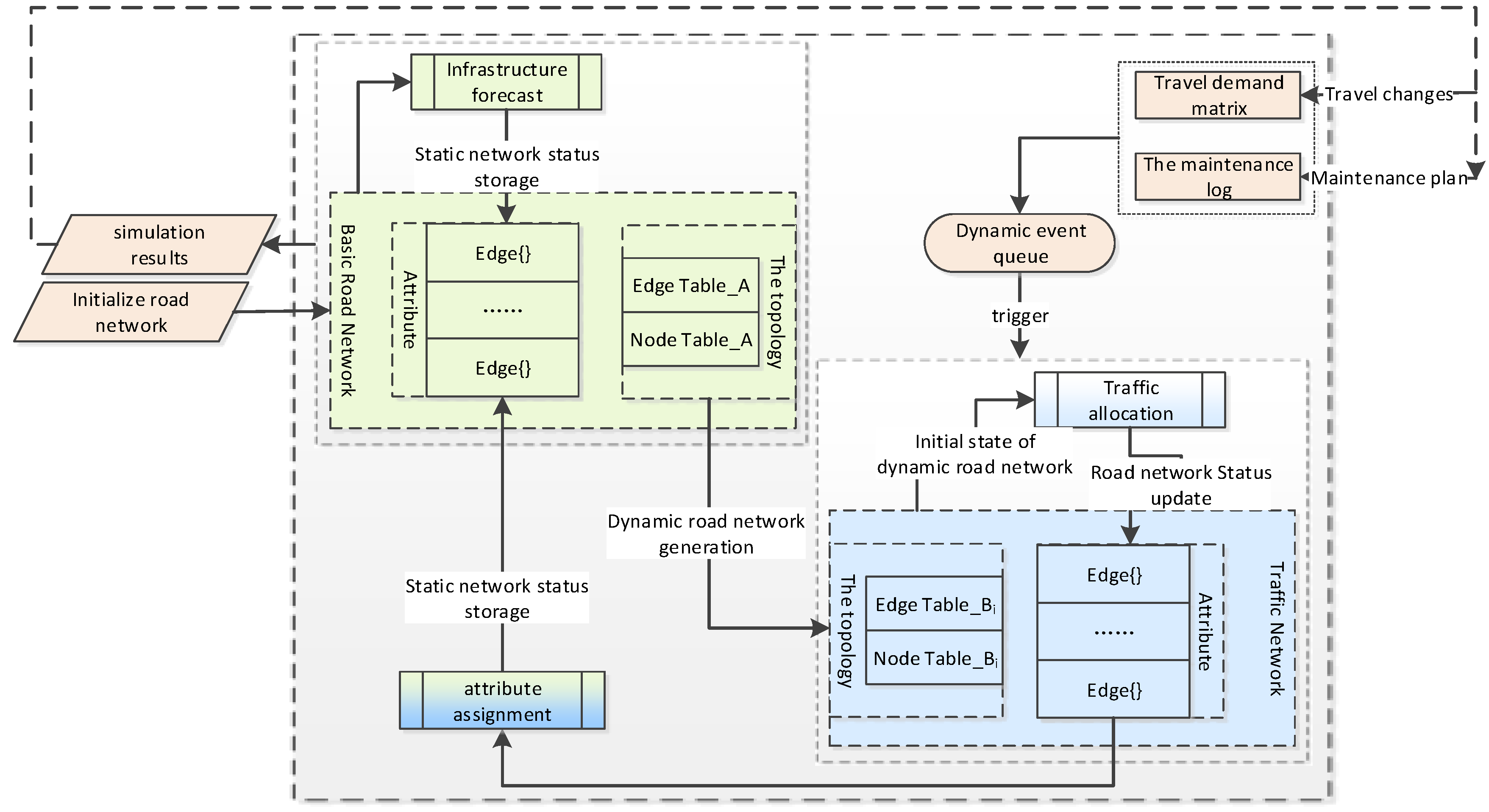
5. Design and Implementation of Coupling Simulation Based on the Dynamic Road Network Model

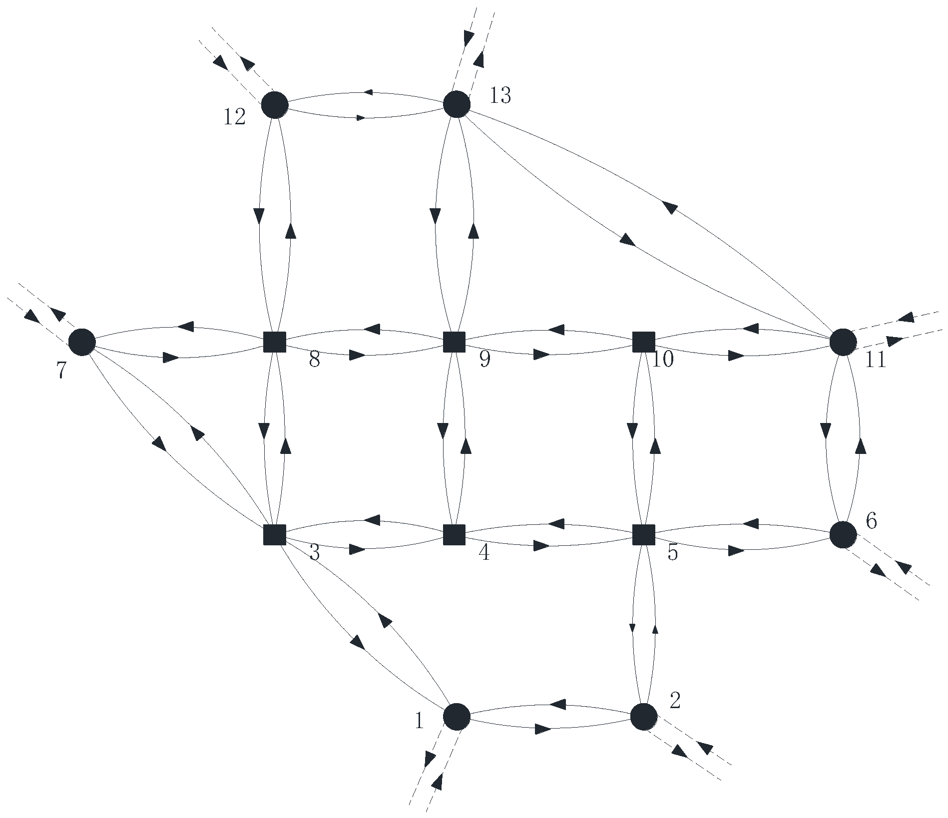
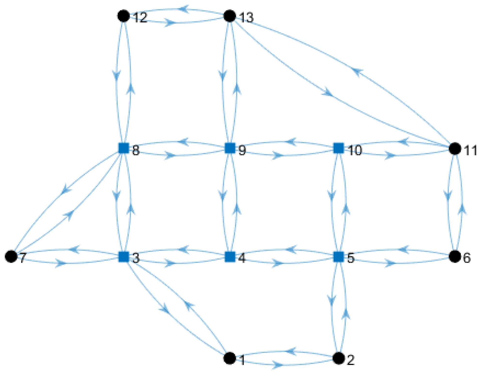
5.1. The Road Network Data

In this section, the Nguyen-Dupuis road network was still selected as the initial road network (Figure 3). The GIS platform was used to initialize the basic data of the road network, and the initial link table (Table 2) and the node table (Table 3) of the road network were obtained. We set the maintenance plan (Table 10), compiled rules according to the maintenance plan and dynamic event table, and completed the event table in the form of a table (Table 8). We set the OD traffic volume per hour as shown in Table 12.

5.2. The Coupling Simulator

Based on the dynamic road network, the coupling relationship between the service performance of road infrastructure and the traffic state of the road network can be considered to simulate the dynamic evolution of the road network state. The method of successive averages (MSA) was used to obtain the passenger car units (PCU) per hour under the dynamic events queue. The accumulative PCU was used as the main traffic index of road infrastructure performance prediction. Road infrastructure performance further influenced the change of road network maintenance plans and formed a dynamic closed loop.
The program execution can be described by the following steps:
Input: Link table (Table 2), node table (Table 3), OD hour traffic volume matrix (Table 12), dynamic event table (Table 8) of the road network (Nguyen-Dupuis, as shown in Figure 3).
Step 1:
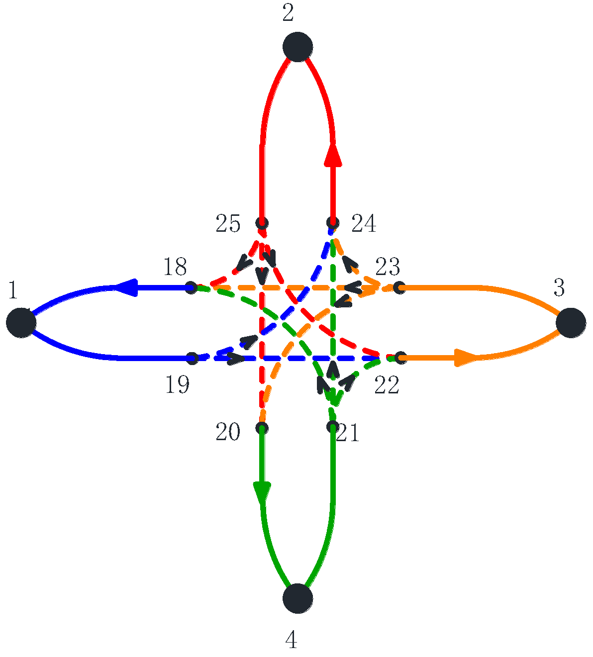
Initialization: construct the initial road network and display (Figure 4), add traffic volume attributes to the road network G0 using the MSA.
Step 2:
The dynamic traffic network G_tr0: according to the dynamic events to call the generation program. To search key nodes, add/delete Nodes and Edges table (Table 5 and Table 6). Expand corresponding components of initial road network G0 and output dynamic traffic network G_tr0 and historical event parameters.
Step 3:
The dynamic traffic network G_tr1: G_tr0 is used as input; call the traffic allocation function to obtain new traffic attributes and store them in the traffic network G_tr1.
Step 4:
The static basic road network G0_1: according to the historical parameters of the event, call the assignment program. Store the traffic attributes of this period to the static basic road network G0→G0_1;
Step 5:
The static basic road network G0_2: call the infrastructure performance prediction function and static road network G0_1 as input, calculate decay index (such as PCI) at the specified time, and store it in the static road network G0_1→G0_2;
Step 6:
The dynamic events table (Table 8): call the maintenance plan subroutine (the purpose is to adjust the maintenance plan according to decay, etc. In this paper, planned maintenance is used to replace the structural change in the whole stage, and maintenance plan update is not considered) to update the dynamic events;
Step 7:
repeat Step 2 to Step 6 until the end of the simulation cycle.
Output: the road network document.

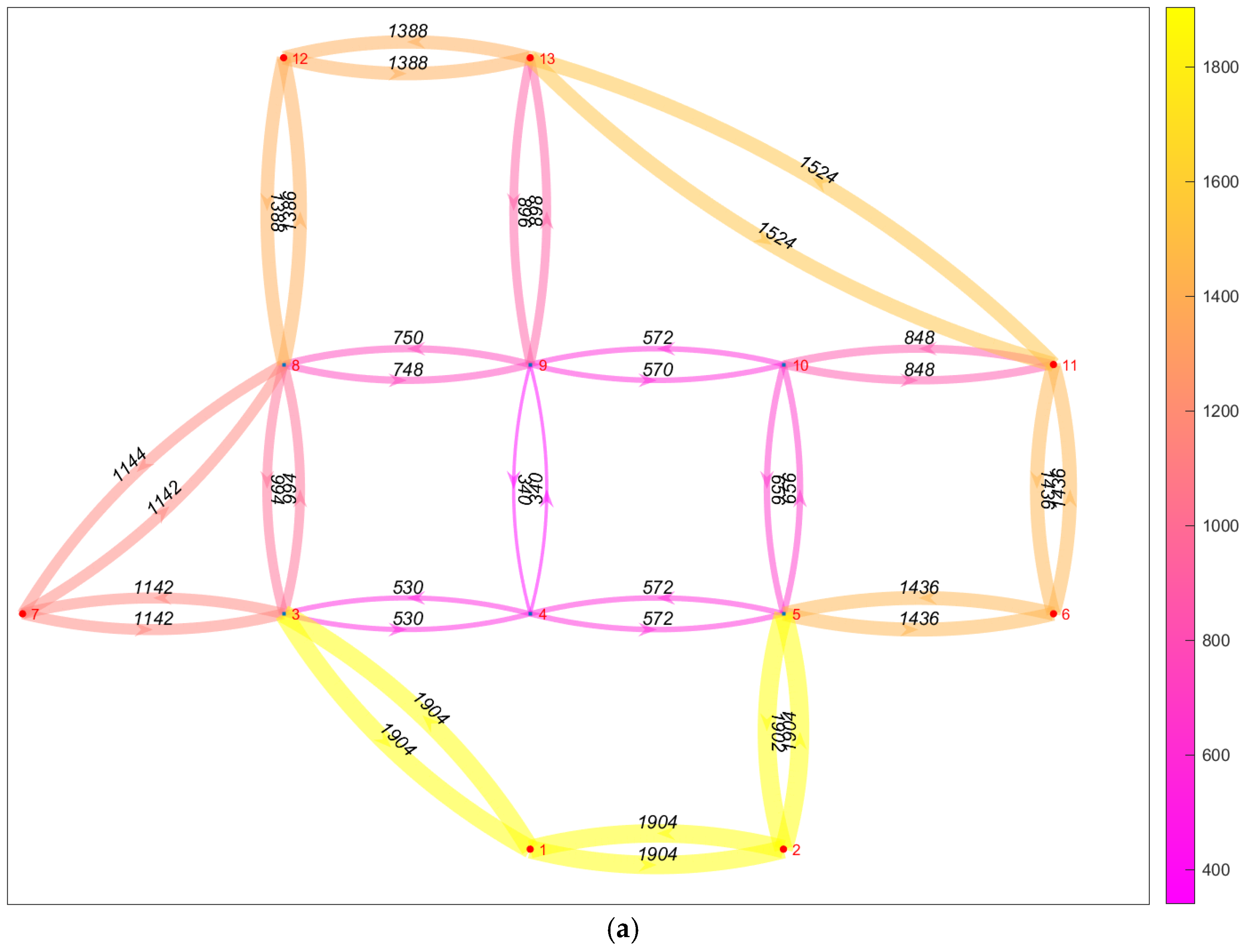
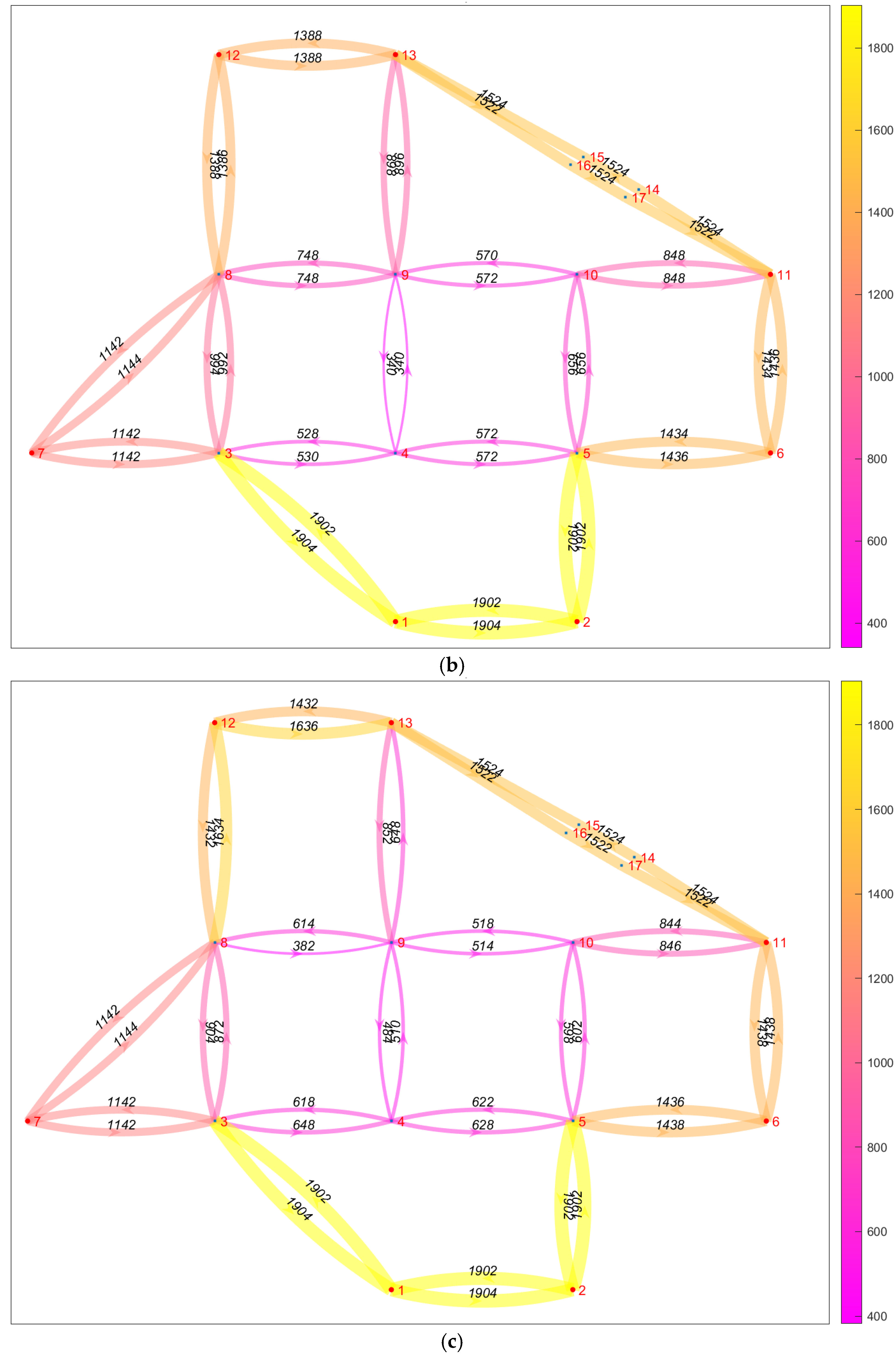
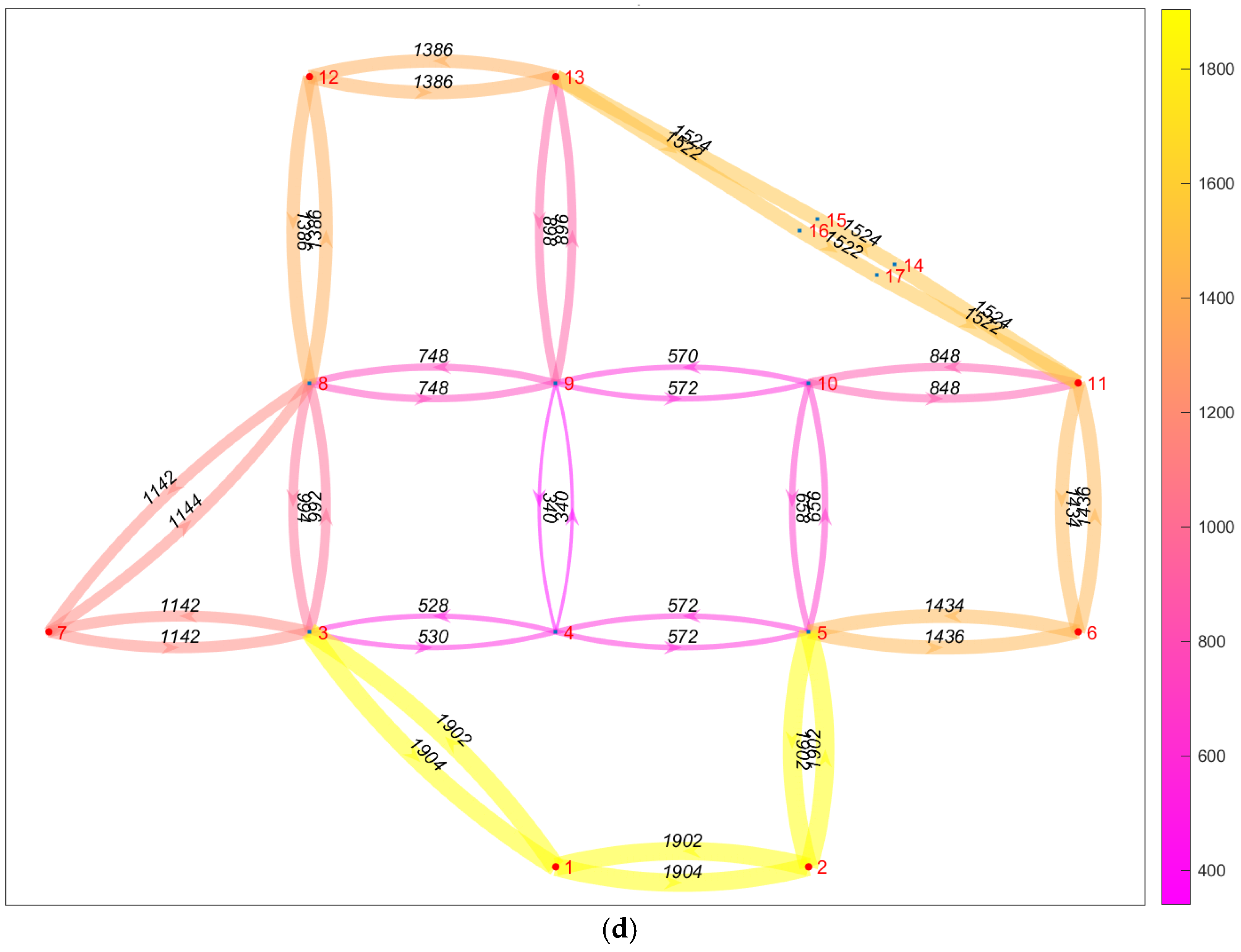
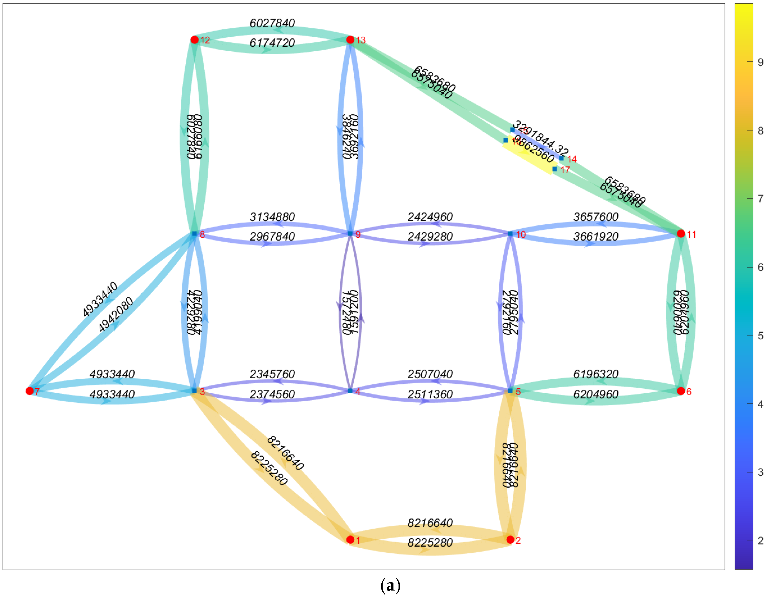
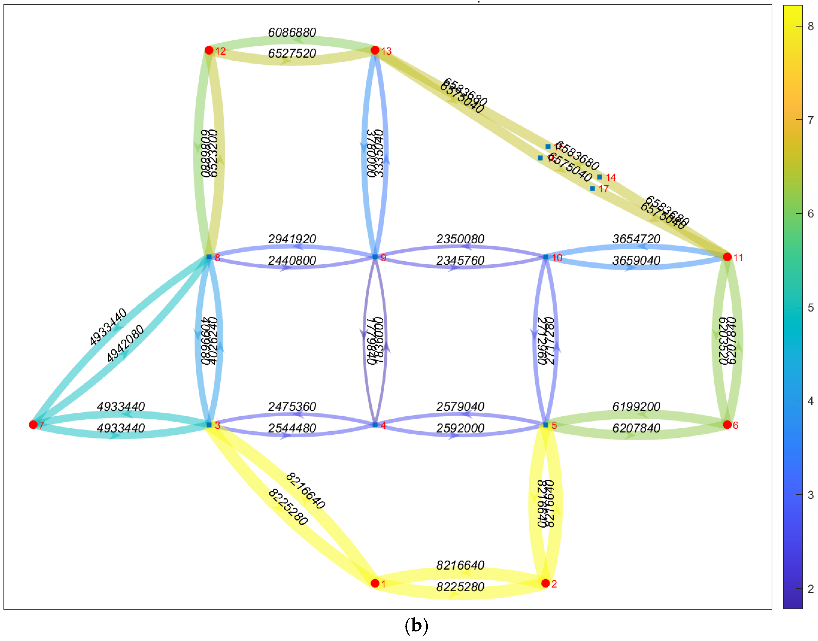
5.3. Results and Analysis

PCU per hour of the link on the dynamic road network (Figure 8) is obtained to reflect the changes in traffic state under events containing spatio-temporal information. The cumulative annual traffic volume stored in the static road network (Figure 9) reflects the rate of decay of the road infrastructure performance. The coupled simulation results of road infrastructure performance and traffic state should include traffic state and road infrastructure performance prediction results in different periods. Since the decay prediction model of road infrastructure is not the focus of our study here, the cumulative annual traffic volume is chosen as the performance decay traffic factor to represent the performance decay of road facilities.
Figure 8 shows the dynamic evolution of the hourly PCU with the traffic network and can be meticulously reflected in the local sections. For example, in the second stage, links 11 to 13 are divided into three sections due to local one-way closure control. In the third stage, the traffic state of the surrounding links changes due to the separate closure measures of the stereo crossing ramp at node 9.
It should be noted here that, from the perspective of traffic allocation, there is no significant difference between the second stage (Figure 8b) and the first stage (Figure 8a) for sections from 11 to 13. This is because after the section is closed in the second stage, the management method of lane passage is adopted, so the attributes, such as road capacity, change, but the traffic network topology does not change. In the third stage (Figure 8c), the topology of the traffic network changes, leading to changes in the traffic volume of some sections of the traffic network.
Figure 9 shows the traffic attributes stored in the static road network, that is, the accumulated annual traffic volume of road infrastructure in the road network. Due to the influence of traffic redistribution on the road network, we can see that the change of traffic volume at different sections of the road network is not linear, but there will be local mutations. We can see this from the dynamic events, as follows.
First, Figure 8 shows that links 14 to 15 and links 16 to 17 present the same status in the traffic network, but Figure 9a shows that the annual traffic volume of the road infrastructure in these two links is not the same. The difference between the two is the difference between the traffic network and road infrastructure network under specific traffic control in the real world.
Second, due to ramp control, the traffic status of the link connected to node 9 is different at different stages, which is also reflected in the accumulated traffic load.
Based on the above two points, it can be understood that the coupled simulation system can predict the decay of road infrastructure performance under the influence of the traffic network.

6. Discussions and Conclusions

The simulation application results show that based on the dynamic road network model can realize the integrated expression of dynamic information such as traffic state and road infrastructure performance. The dynamic road network model can meet the requirements of different scales of road network structure, data space access and transformation for road infrastructure performance prediction and traffic state dynamic evolution analysis under certain efficiency requirements. The road network description model proposed in this paper takes local components, such as the minimum unit of topology and road sections, as the basic unit of topology. Compared with the traditional link-node centerline static road network model, our model can more accurately describe the connectivity and state of the road network, including unexpected traffic events, component discrepancy decay, etc. Compared with the lane-based road network model, it has higher analysis efficiency.
Simulation experiments based on a dynamic road network model setup can quantitatively analyze the coupling mechanism of road infrastructure performance and road network traffic state. The efficient computing power of a computer is used to imitate the overall evolution of a large-scale road network state. The simulation results can provide a basis for road network management and planning. In addition, the dynamic road network model is also applicable to the simulation of the dynamic evolution of traffic caused by short-term accidents. We can do this by building an appropriate path selection model. The simulation can analyze the dynamic evolution of traffic caused by short-term accidents in the current state of road facilities. This can provide a basis for traffic management.
In the future, we need to study reasonable traffic analysis models and road facility performance prediction models to reflect the real dynamic evolution of road network states. This includes, for example, dynamic traffic evolution models that can more accurately reflect the road network traffic flow in response to the decay of road facility service performance. This requires attention to the long-term driving habits of heavy-duty vehicle users to establish a reasonable path selection model and road traffic flow model. In the analysis of the short-term dynamic traffic evolution of the road network, more attention is paid to the short-term response of drivers to unexpected events. The evolution of traffic distribution on the road network is reflected by the microscopic traffic flow model. It provides a basis for formulating traffic management strategies.

Author Contributions

Conceptualization: Z.Y. and R.Z.; methodology, Z.Y. and R.Z.; coding, Z.Y. and R.Z.; writing—original draft preparation, R.Z.; writing—review and editing, Z.Y. and R.Z.; visualization, Z.Y. and R.Z.; supervision, Z.Y., R.Z. and K.Z.; project administration, Z.Y. and G.W. All authors have read and agreed to the published version of the manuscript.

Funding

This study was supported by the Science and Technology Commission of Shanghai Municipality (20dz1203000), the National Key Research and Development Plan of China (Grant No. 2018YFB1600301).

Institutional Review Board Statement

Not applicable.

Informed Consent Statement

Not applicable.

Data Availability Statement

Not applicable.

Conflicts of Interest

The authors declare no conflict of interest.

References

  1. Tom, R. Design requirements for location as a foundation for transportation information systems. In Proceedings of the GIS-T’93: Geographical Information Systems for Transportation Symposium; AASHTO: Albuquerque, NM, USA, 1993; pp. 48–66. [Google Scholar]
  2. Shi, J.L.; Li, G.N.; Zhou, L.C.; Lu, G.N. Lane-Level Road Network Construction Based on Street-View Images. IEEE J.-Stars 2022, 15, 4744–4754. [Google Scholar] [CrossRef]
  3. Zheng, L.; Li, B.; Yang, B.; Song, H.; Lu, Z. Lane-Level Road Network Generation Techniques for Lane-Level Maps of Autonomous Vehicles: A Survey. Sustainability 2019, 11, 4511. [Google Scholar] [CrossRef]
  4. Timpf, S.; Volta, G.S.; Pollock, D.W.; Egenhofer, M.J. A Conceptual-model of Wayfinding Using Multiple Levels of Abstraction. Lect. Notes Comput. Sci. 1992, 639, 348–367. [Google Scholar] [CrossRef]
  5. Zhu, Q.; Li, Y. Hierarchical lane-oriented 3D road-network model. Int. J. Geogr. Inf. Sci. 2008, 22, 479–505. [Google Scholar] [CrossRef]
  6. Wang, J.; Lawson, G.; Shen, Y. Automatic high-fidelity 3D road network modeling based on 2D GIS data. Adv. Eng. Softw. 2014, 76, 86–98. [Google Scholar] [CrossRef]
  7. Zhang, X.Q.; Zhong, M.; Liu, S.B.; Zheng, L.H.; Chen, Y.M. Template-Based 3D Road Modeling for Generating Large-Scale Virtual Road Network Environment. ISPRS Int. J. Geo-Inf. 2019, 8, 364. [Google Scholar] [CrossRef]
  8. Fohl, P.; Curtin, K.M.; Goodchild, M.F.; Church, R.L. A Non-Planar, Lane-Based Navigable Data Model for ITS. In Proceedings of the Seventh International Symposium on Spatial Data Handling, Delft, The Netherlands, 12–16 August 1996. [Google Scholar]
  9. Li, X.; Lin, H. A trajectory-oriented, carriageway-based road network data model, Part 2: Methodology. Geo-Spat. Inf. Sci. 2006, 9, 112–117. [Google Scholar] [CrossRef]
  10. Vermote, L.; Macharis, C.; Putman, K. A Road Network for Freight Transport in Flanders: Multi-Actor Multi-Criteria Assessment of Alternative Ring Ways. Sustainability 2013, 5, 4222–4246. [Google Scholar] [CrossRef]
  11. Li, X.; Wang, M.; Liu, X.; Wang, Z.; Bian, Y. Representing dynamic lanes in road network models. Int. J. Geogr. Inf. Sci. 2022, 36, 1467–1483. [Google Scholar] [CrossRef]
  12. Chen, Y.; Wu, C.; Yao, M. Dynamic Topology Construction for Road Network. In Proceedings of the 2008 Fourth International Conference on Networked Computing and Advanced Information Management, Gyeongju, Korea, 2–4 September 2008; pp. 359–364. [Google Scholar]
  13. Yang, Y.; Han, X.; Yuan, Z. A Model of the Dynamic Traffic Road Network. IERI Procedia 2012, 3, 46–51. [Google Scholar] [CrossRef] [Green Version]
  14. Ren, G.; Wang, W. Study on Dynamic Transportation Network and its Model in Transportation Planning. J. Highw. Transp. Res. Dev. 2002, 19, 108–111. [Google Scholar]
  15. Chen, Y.; Chen, S. Complexity Topology of Highway Network with Information of Interchange Ramps. J. Tongji Univ. 2010, 38, 230–237. [Google Scholar] [CrossRef]
  16. Ying-fei, Q.I.; Ben-min, L.; Zhong-yin, G. Application and modeling of freeway traffic networks based on traffic flow characteristics. Comput. Eng. Appl. 2007, 43, 244–248. [Google Scholar]
  17. Raju, N.; Arkatkar, S.; Joshi, G. Effect of Construction Work Zone on Traffic Stream Parameters Using Vehicular Trajectory Data under Mixed Traffic Conditions. J. Transp. Eng. Part A Syst. 2020, 146. [Google Scholar] [CrossRef]
  18. Chen, D.H.; Zhou, F.J.; Cortez, E.R. Determination of load damage relationships through accelerated pavement testing. J. Test. Eval. 2006, 34, 312–318. [Google Scholar] [CrossRef]
  19. Nguyen, S.; Dupuis, C. An Efficient Method for Computing Traffic Equilibria in Networks with Asymmetric Transportation Costs. Transp. Sci. 1984, 18, 185–202. [Google Scholar] [CrossRef]
  20. Dueker, K.J.; Butler, J.A. GIS-T enterprise data model with suggested implementation choices. URISA J. 1998, 10, 12–36. [Google Scholar]
Figure 1. Basic topology.
Sustainability 14 11521 g001
Figure 2. Extended topology.
Sustainability 14 11521 g002
Figure 3. Nguyen-Dupuis road network. (● indicates OD points; ■ indicates intermediate nodes).
Sustainability 14 11521 g003
Figure 4. Nguyen-Dupuis road network as shown in MATLAB. (● indicates OD points; ■ indicates intermediate nodes).
Sustainability 14 11521 g004
Figure 5. Dynamic road network conceptual model.
Sustainability 14 11521 g005
Figure 6. Main road Section 1 → 2 lane partial construction operation closure program.
Sustainability 14 11521 g006
Figure 7. Separate closure program for 1 → 4 turn ramp at the interchange.
Sustainability 14 11521 g007
Figure 8. Dynamic traffic network attribute-traffic state: PCU per hour. (a) Results of balanced traffic allocation in the first stage of the traffic network. (b) Results of balanced traffic allocation in the second stage of the traffic network. (c) Results of balanced traffic allocation in the third stage of the traffic network. (d) Results of balanced traffic allocation in the fourth stage of the traffic network.
Sustainability 14 11521 g008aSustainability 14 11521 g008bSustainability 14 11521 g008c
Figure 9. Static base road network attributes: annual cumulative PCU. (a) Cumulative traffic volume in the first year of the road network. (b) Cumulative traffic volume in the second year of the road network.
Sustainability 14 11521 g009aSustainability 14 11521 g009b
Table 1. Extended topology.
LocationApplication
Main roadFirst, a section is enclosed separately
Second, some road infrastructure (bridge, tunnel, road surface, etc.) on a certain section or the same section is not consistent with the adjacent road infrastructure
Hub interchange, Toll stationA ramp does not exist or is separately closed during
operation
Table 2. Link table of the Nguyen–Dupuis road network.
EdgesLengthSeparatedCap_d1Cap_d2Speed_d1Speed_d2PCI1PCI2
FNodesTNodes
1227951220022001201208080
3138471220022001201208080
4326841220022001201208080
5428321220022001201208080
2527191220022001201208080
6529801220022001201208080
7340731220022001201208080
7828811220022001201208080
3828791220022001201208080
8926841220022001201208080
9428791220022001201208080
91028321220022001201208080
51028791220022001201208080
101129801220022001201208080
11628791220022001201208080
81235431220022001201208080
121326841220022001201208080
13935431220022001201208080
131168071220022001201208080
Table 3. Node table of the Nguyen–Dupuis road network.
FID_nodeID
11
21
30
40
50
61
71
80
90
100
111
121
131
Table 4. Basic data elements in node table.
No.Column IndexTypeDescriptionWhether
Row Index
1FID_nodeIntegerNode numberYes
2IDIntegerWhether OD points (0/1)No
Table 5. Basic data elements in link table.
No.Column IndexTypeDescriptionWhether Row IndexNote
1Edgesarray[Start node ID, End node ID]YesA section of the road having the same characteristics
2SeparatedIntegerWhether or not to separate from the roadway in the opposite directionNoConnectivity limitation: separate, cannot change the central partition belt for connectivity
3NameCharacterRoute nameNooptional
4LengthDoubledistanceNoThe number of table rows can be increased or decreased depending on the number of lanes
5SpeedDoubleLane design speedNo
6Cap_dDoubleLane design capacityNo
7PerformanceDoubleService performance indicatorsNoPerformance can be added as PCI, RQI, RDI, SRI, PSSI, PQI, etc.
8FlowDoubleLane traffic volumeNoThe number of table rows can be increased or decreased depending on the number of lanes
9TDoubleLane travel timeNo
Table 6. Dynamic editable content table.
ContentOperationAttributeApplication
Add nodes/linksTraverses the node table row index to find the maximum node number MaxID;
Add 2 rows to the node table. The row index identifiers are MaxID + 1 and MaxID + 2.
Add 1 row to link table with row index identifier [MaxID + 1, MaxID + 2].
Inheritance/additionNew road: add a link on behalf of new;
a link is partially weakened/repaired due to traffic control or functions of sections: new links are added to realize segmental access to different attributes of the links;
the ramp of the interchange is closed separately: N links are added to represent the steering connection relationship.
Delete nodes/linksTraverse the row index of the link table to find the link identifier to be deleted and delete it.
No operation is performed on the node table.
-A link is severely weakened due to traffic control or function: delete link;
a link is partially weakened/repaired due to traffic control or functions of sections: delete the link before new links are added to realize segmental access to different attributes of the link;
resumption of the ramp at the interchange: delete the connected section and restore the originally connected relationship.
Change the attribute of nodes/linksTraverse the link table row index to find the link identifier that needs to be changed and change it.ReassignmentAssign values to the traffic data and performance data in different periods, or accompany the scenario of adding nodes/links.
Table 7. The objects of the dynamic road network model.
ObjectsBasic UnitCharacteristicsApplicability
Basic network layerActual lanesThe actual lanes in the road network are abstracted as directed elements, and the attributes of the actual road infrastructure (lanes) are stored.Infrastructure state characterization and decay prediction and result storage
Traffic network layerTraffic lanesThe actual traffic direction lane is abstracted as directed line elements to represent the actual traffic network topologyTraffic state characterization and evolution simulation and result storage
Table 8. Dynamic events.
TimeEventParameter
[01012020, 30042020]0nannan
[1052020, 30102020]11, 11, 13, 2500, 1000nan
[1112020, 30062021]28, 13; 10, 49; 5
[1072021, 30122021]0nannan
Table 9. Dynamic event editing rules.
IdentifierParaphraseRules
TimeEvent time[(date) (month) (year), (date) (month) (year)]
EventEvent type(0,1,2,3)
ParameterEvent parametersTable 10 for details
Table 10. Event parameters editing rules.
Event IdentifierEvent ParametersParameter MeaningRepresentative Scenes
Event Parameters_1Event Parameters_2
0nannan-No event.
1<TNode, Enode, Length>nanTNode and ENode are the start and end node ids of the link, respectively, and Length is the length of the new link (m).A new link in the network.
2<LnNum, TNode, ENode, TDistance, Length>nanLnNum is the number of lane closures, TNode and ENode are the starting and ending node IDS of the link, respectively, TDistance is the distance between the starting point of the closed section and TNode of the link, and Length is the length of the closed section (m).Lane closure, lane compression, or diversion to the opposite lane.
3< TNode_1, ENode_1; TNode_2, ENode_2;
……>;
<JNode_1; JNode_2;
……>
JNode is an interchange node, and the turn ramp of TNode to ENode is closed. N directions can be enclosed individually or in combinationN interchange ramps separately closed.
Table 11. Conservation plan.
TimePlan EventsPlan Event Location
Description
Months 1~4No eventNo event
Months 5~10Partial closure diversion for construction workLink11 → 13, Range of
2500 to 3500 m from 11 nodes
Months 11~18Ramps are individually closedNode 8 → node 13 steering ramp, node 10 → node 4 steering ramp; the nodes of interchange are nodes 9 and 5.
Months 18~24No eventNo event
Table 12. OD traffic volume per hour.
Node ID.1267111213
10730731731731730731
27300730731731731730
67317310731731731730
77307317310731730730
117307307307300731730
127307317307317310730
137307317317307307310
Publisher’s Note: MDPI stays neutral with regard to jurisdictional claims in published maps and institutional affiliations.

