Article

Influence of Defects on In-Plane Dynamic Properties of Hexagonal Ligament Chiral Structures

1
School of Technology, Beijing Forestry University, Beijing 100083, China
2
School of Mechanical Engineering, University of Science and Technology Beijing, Beijing 100083, China
3
Batten College of Engineering and Technology, Old Dominion University, Norfolk, VA 23529, USA
*
Author to whom correspondence should be addressed.
Sustainability 2022, 14(18), 11432; https://doi.org/10.3390/su141811432
Submission received: 9 August 2022 / Revised: 8 September 2022 / Accepted: 9 September 2022 / Published: 12 September 2022

Abstract

:
Although the six-ligament chiral structure has many unique properties, due to its special structure, the stress concentration is prone to defects. In addition, additive manufacturing is also prone to defects. This paper studies the effect of defects, which is helpful for the better application of the six-ligament chiral structure. Several new six-ligament chiral structures with random and concentrated defects were designed to explore the effects of the defects on the in-plane dynamic properties. The structures were studied with the finite element ANSYS/LSDYNA numerical simulation and experimental methods. According to the defect-free six-ligament chiral structures exhibiting different deformation modes at different impact velocities, the effects of the defect rate and type (concentrated and random defects) on the six-ligament chiral structure, the in-plane impact deformation mode and energy absorption characteristics are discussed. The research results show that the defect rate and type reduce the energy absorption characteristics of the chiral structure to varying degrees, and the impact deformation mode also changes under medium- and low-speed impact. With the increase in speed, the influence of the defects on the deformation mode weakens. Moreover, the effects of the concentrated and random defects on the platform stress are different. When the defect rate is low, the effect of the random defects is more significant, and as the defect rate increases, the effect of the concentrated defects is more obvious. The study can provide guidance for structural design, predict the failure form of structures containing defects when they are impacted, and realize material recycling.

1. Introduction

A chiral structure is a kind of lightweight honeycomb structure. Compared with ordinary honeycomb materials [1,2,3,4,5,6,7], it has a higher specific strength and specific energy absorption capacity and can be used as a protective device for explosions and impacts. At the same time, the six-ligament chiral honeycomb structure has a special negative Poisson’s ratio. The negative Poisson’s ratio property is that when a structure is stretched in the longitudinal direction, it expands in the transverse direction. As a result, during compression, the density of the internal structure increases, improving the compression and impact resistance. Materials with negative Poisson’s ratio properties are also called auxetic materials. The formation mechanism of a negative Poisson’s ratio effect includes the stretching mechanism and rotation mechanism. Auxetic materials have better indentation resistance than non-negative Poisson’s ratio materials. Due to their unique deformation forms and mechanical potential, chiral auxetic structures have potential applications in stretchable electronics, biomedical devices, electronic skin, scaffolds, and reconfigurable soft robotics [8,9,10,11,12,13,14,15].
Using analytical, experimental, and simulation methods, researchers have systematically studied the chiral structure. Studies have included the in-plane mechanical properties [8,9,16,17,18,19,20,21,22,23] and out-of-plane mechanical properties [18,24,25] of chiral structures under quasi-static and dynamic loading. Zhang et al. [16] studied the effects of the geometric parameters on the elastic modulus and Poisson’s ratio of the six-ligament chiral structure. The study of Mauko et al. [19] confirmed the Poisson’s ratio strain-rate dependency. Airoldi et al. [26] combined numerical and experimental methods to study a novel structure with the addition of foam padding in a six-ligament chiral structural metal frame. It improved the energy absorption capacity and load uniformity. Qiu et al. [27] used the good designability of chiral structures to design a flexible chiral honeycomb structure for use in deformable aircraft. Gao et al. [28] studied the influence of the geometric parameters of the six-ligament chiral structure, as well as the external factors (impact mass and impact velocity), on the structural crashworthiness parameters. With the increasing application prospects of chiral auxetic structures, some scholars have studied the deformation mechanism of spatial 3D auxetic chiral structure compression [8,9,10,11,12,13,14,15]. Xin et al. [29] modified the traditional six-ligament chirality to improve the tunability of the parameters. In addition, experiments have shown that negative Poisson’s ratio chiral structures have stronger mechanical properties than ordinary 3D chiral structures. At the same time, the design of geometric parameters can achieve a large change in the elastic constant. Different mechanical properties and Poisson’s ratios can be obtained.
Most of the previous researches improved the mechanical properties of the six-ligament chiral structure through novel designs but ignored the effects of defects on the mechanical properties. The six-ligament chiral structure is generally processed by additive manufacturing [29,30,31]. The study by Gwanho et al. [32] showed that additive manufacturing has limited controllability and uniformity during processing and is prone to defects. Whether the performance requirements are met when the chiral structure is defective needs to be evaluated. Existing studies on defects are mostly related to ordinary honeycomb structures [7,33,34,35,36]. Hu et al. [33] studied the effect of random defects on the deformation form of gradient honeycomb structures. He et al. [35] studied the influence of inclusions in different regions on the stress of honeycomb structures. Sri et al. [36] studied the effect of the cell-wall deletion rate and deletion location on energy absorption. The in-plane dynamic properties of chiral materials with negative Poisson’s ratio properties are slightly different so the effects of defects on chiral structural properties need to be studied in depth. First, through theoretical research, we can understand the degree of influence of different defects on the structural properties. This can provide a reference for the design of chiral structures and strengthen the design of structural weaknesses. Second, additive manufacturing has high time and economic costs. Whether the structure still meets the performance requirements needs to be explored if defects are generated during processing. Finally, the research of defects is also of great significance to realizing the recycling and sustainable utilization of materials. If the structure fails due to defects during use, this can be applied to the fields or components with lower performance requirements, which requires the theoretical background of the degree of influence of defects on the structure. Therefore, the study of the defective six-ligament chiral structure provides a reference for the recycling of materials.
In this paper, several six-ligament chiral structures with random and concentrated defects are designed, and the in-plane dynamic properties of the six-ligament chiral structures with defects are discussed. The deformation, platform stress, and energy absorption capacity of the six-ligament chirality were studied by combining numerical simulation and experimental methods. This can provide guidance for the application of the structures in the automotive and aerospace fields, as well as provide a reference for defect prevention.

2. Design of Experimental and Simulation Methods

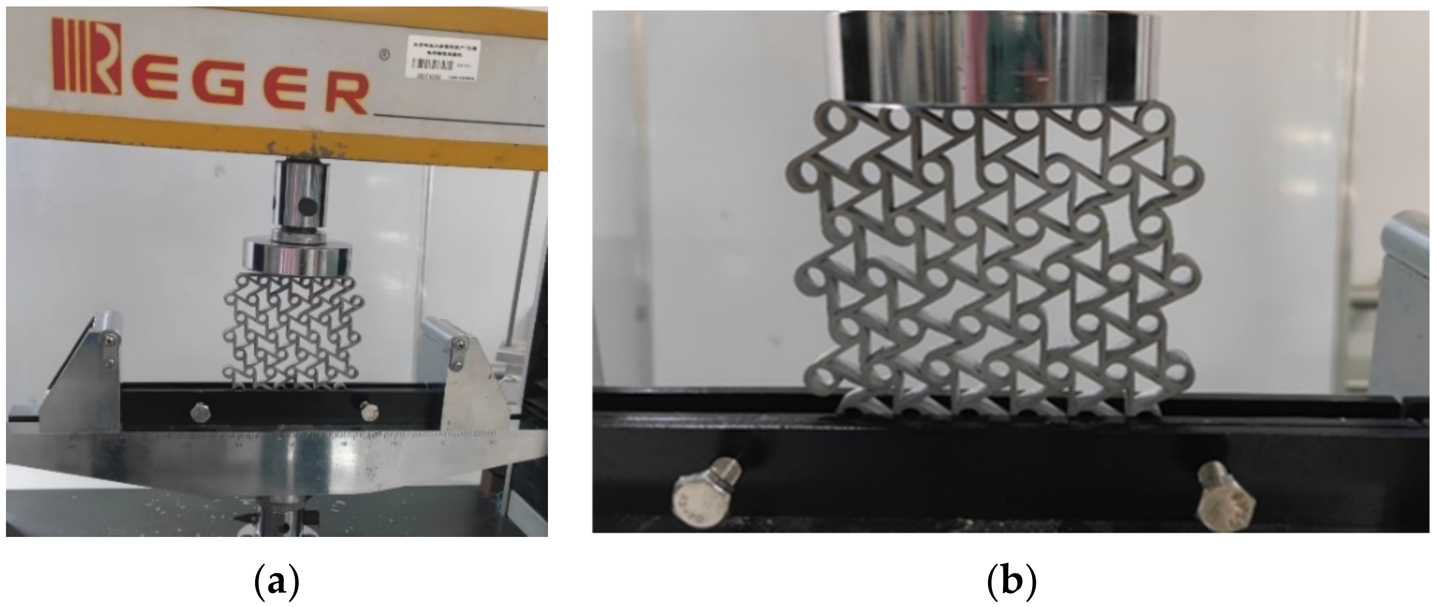
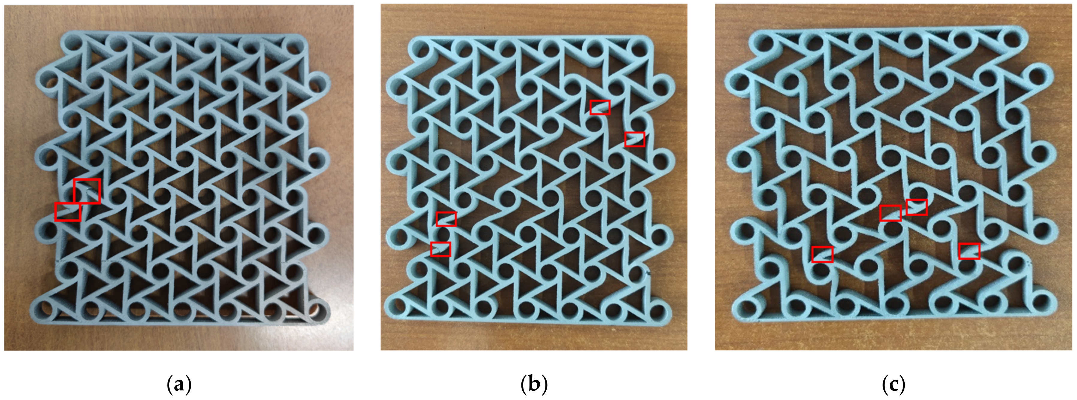
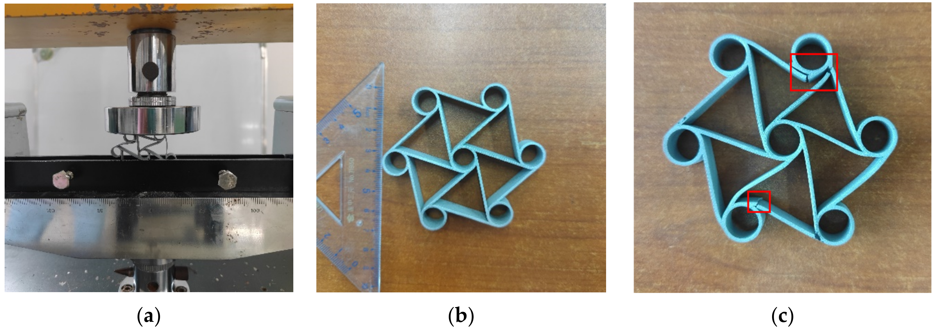
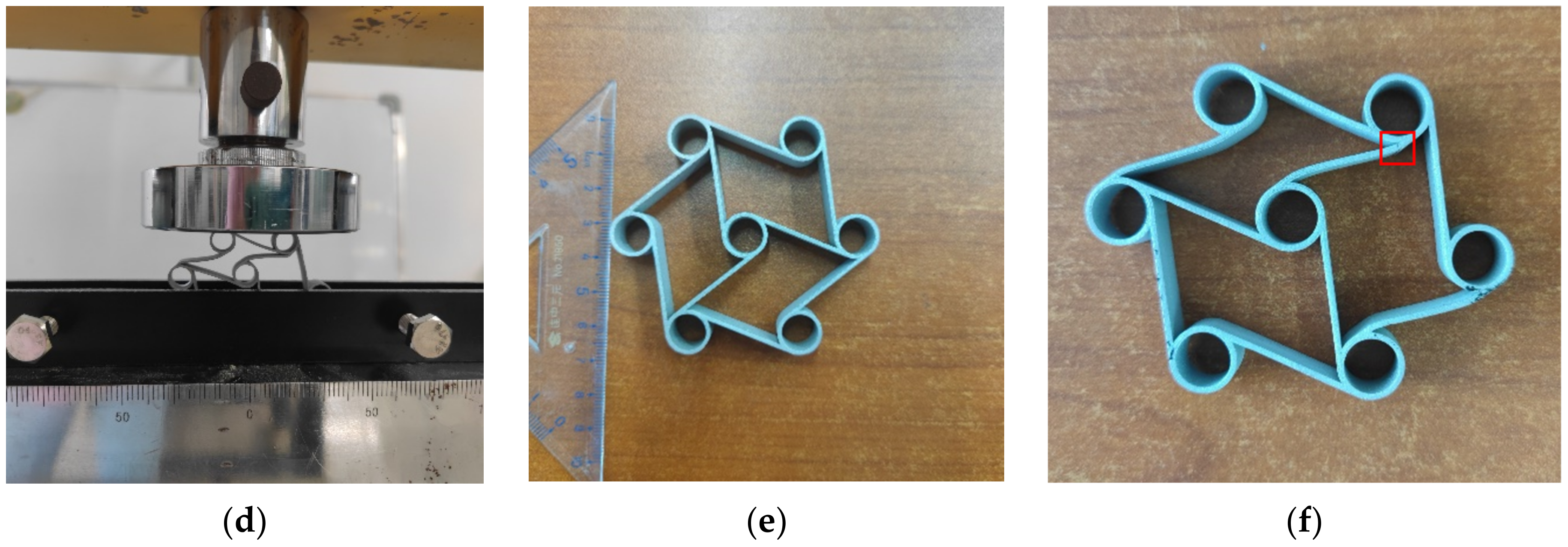
2.1. Experimental Method Design

The material used in the test was aluminum alloy 6061, and the mechanical properties of the material were obtained through reference [37] and tensile tests. The test samples were prepared by 3D printing. During the test, the sample was fixed by a fixture. It could limit out-of-plane deformation to a certain extent. Quasi-static compression tests were performed on a REGER universal testing machine with a compression rate of 5 mm/min. The test setup is shown in Figure 1. Finally, the force and displacement curves were collected.

2.2. Finite Element Simulation
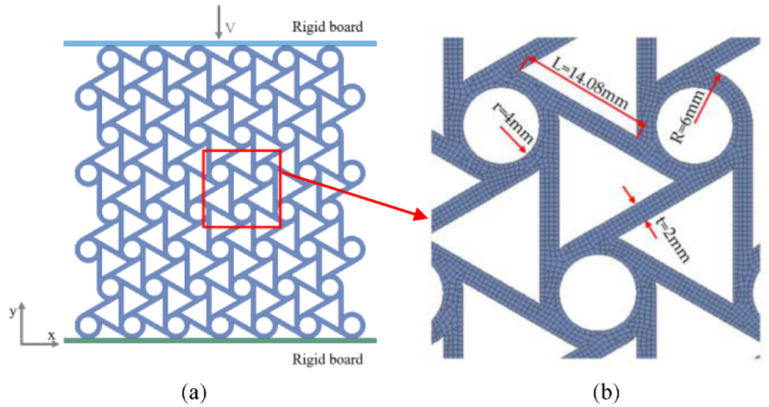
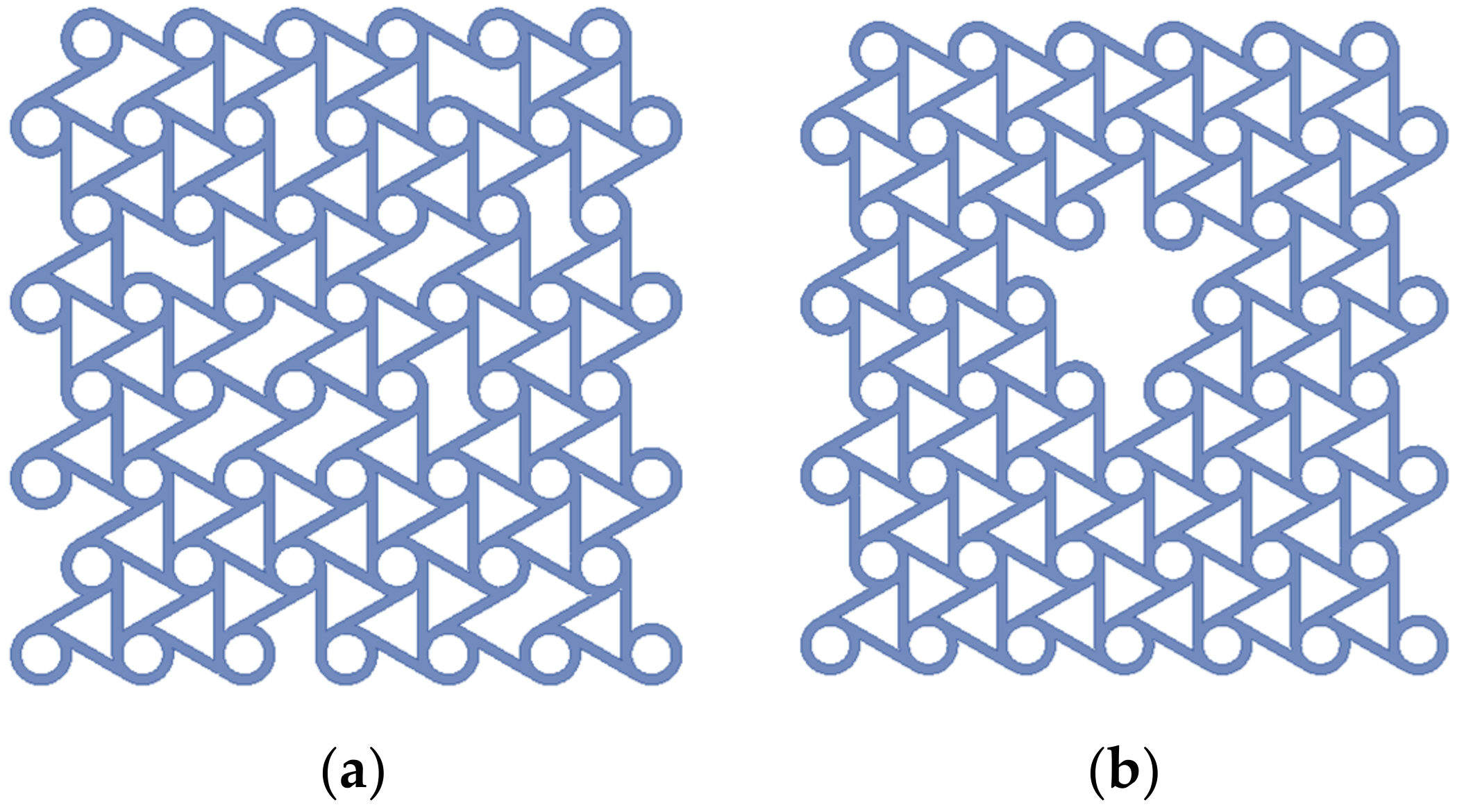
2.2.1. FE Modelling

The simulation of in-plane impact dynamics was performed using the explicit dynamic finite element soft ANSYS/LSDYNA (a highly nonlinear dynamic analysis software). The base material was metal aluminum and the ideal elastic–plastic model was adopted. The elastic modulus was 69 GPa, the yield stress was 76 MPa, the material density was 2700 kg/m3, and the Poisson’s ratio was 0.3. The cells inside the structure were defined as CONTACT_AUTOMATIC_SINGLE_SURFACE. The structure and the rigid plate were defined as CONTACT_AUTOMATIC_SURFACE_TO_SURFACE. The rigid plate and structure were regarded as frictionless. The bottom rigid plate was fixed and the top rigid plate impacted along the y direction at a speed of V. The two sides were free boundary conditions and the displacement in the z direction was limited in order to keep the structure in a state of plane strain. The established defect-free six-ligament chiral structure model and mesh division are shown in Figure 2.
The size of the specimen was L1 × L2 = 132.00 mm × 133.24 mm, with 10 cells in the x direction and 7 cells in the y direction. The defect types were divided into random and concentrated defects, as shown in Figure 3. The ligaments with random defects in this paper were selected using MATLAB software (R2022a, Natick, MA, USA) to generate random numbers. Because the structural material and thickness in the z direction were the same, the defect rate can be expressed as
φ = M ¯ M = S ¯ S
where M ¯ is the mass of the missing part, M is the total mass of the structure, S ¯ is the area of the defect site on the XY plane, and S is the total area of the structure on the XY plane.

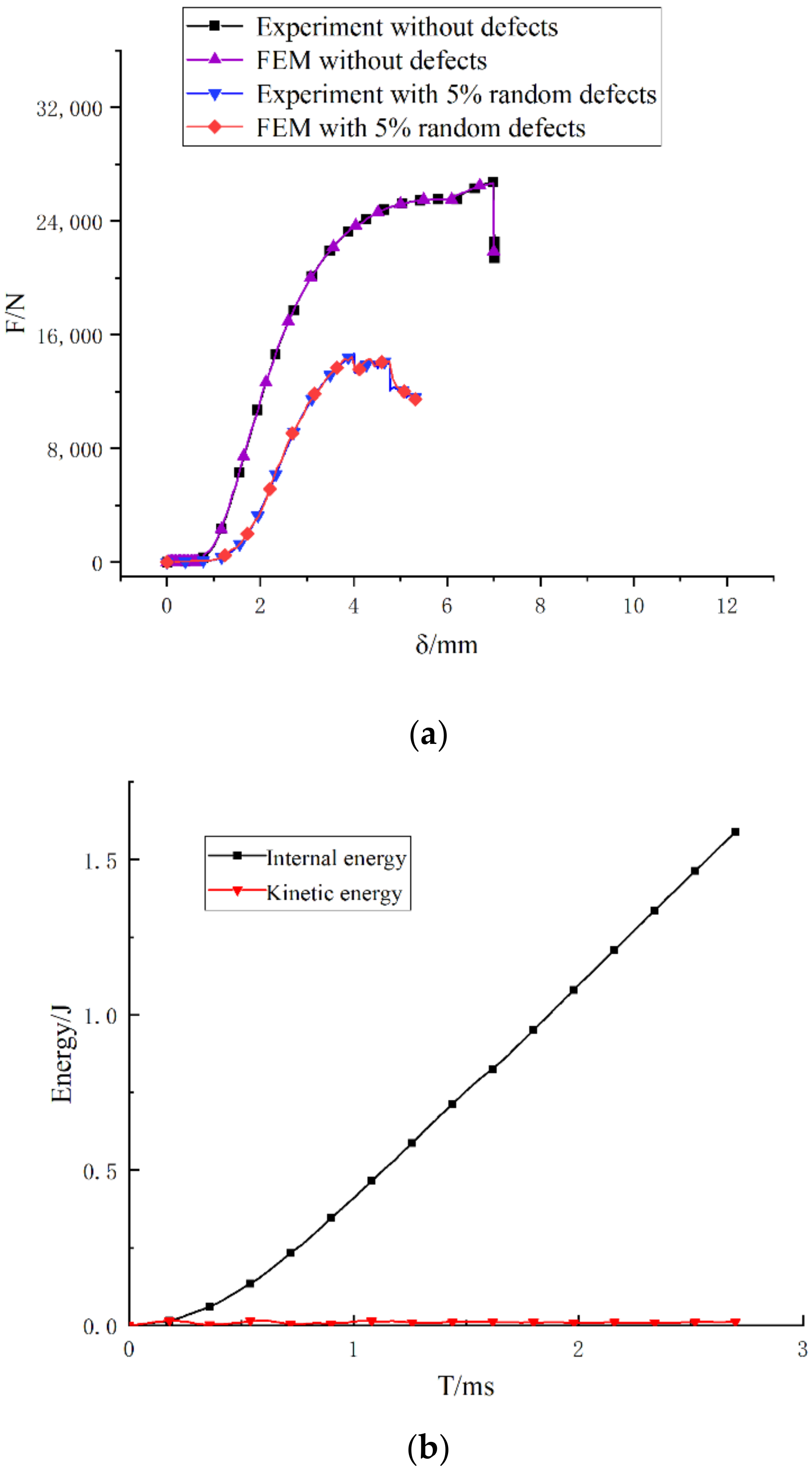
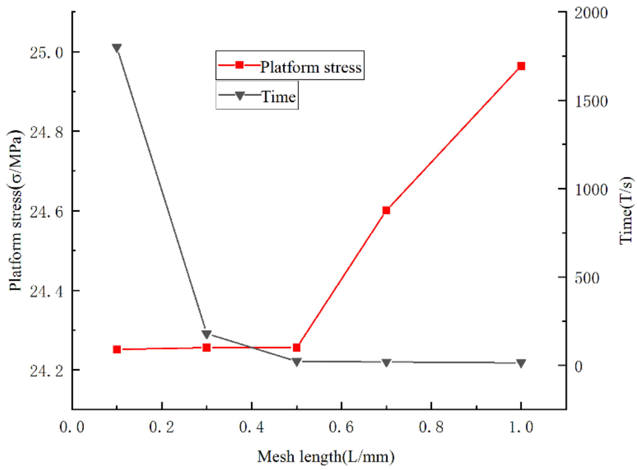
2.2.2. Reliability Analysis of Simulation Model

The quasi-static compression force–displacement curve of the six-ligament chiral structure with the 5% random defects model is shown in Figure 4a. The simulation speed V was 2 m/s. The finite element simulation and experimental results of the structure show the reliability of the numerical simulation. According to reference [38], the kinetic energy of the model is less than 5% of the overall energy, which can be regarded as the quasi-static compression. Figure 4b shows the relationship between the kinetic energy and internal energy of the model when the moving speed was 2 m/s. According to the curve, the kinetic energy was much smaller than the internal energy. Therefore, the model conformed to the quasi-static compression and can be compared with the experimental results.
In order to further study the validity of the established model, the influence of the mesh size on the impact platform stress and simulation calculation time was discussed, and the mesh lengths were 0.1 mm, 0.3 mm, 0.5 mm, 0.7 mm, and 1 mm, respectively (V = 100 m/s). It can be seen in Figure 5 that with the decrease in the mesh division length, the platform stress tended to be stable but the calculation time increased significantly. In order to balance the calculation time and the accuracy of the calculation results, the mesh length of the simulation model in this paper was 0.5 mm.

3. Results of Tests and Simulations

3.1. Evaluation Index of Dynamic Characteristics

The nominal stress σ and nominal strain ε of the six-ligament honeycomb material are expressed as
σ = F A
ε = δ h
where F is the compression reaction force of the rigid board, A is the initial cross-sectional area of the test structure, δ is the compression displacement of the rigid board, and h is the initial height of the structure.
The platform stress is an important indicator to describe the dynamic properties of porous materials. The platform stress of the six-ligament honeycomb material [16] can be written as
σ p = 1 ε d ε 0 ε d σ ε d ε
where ε d is the maximum strain value before the material is compressed and compacted and ε 0 is the nominal strain when the first peak value is reached in the stress–strain curve.
An important indicator for evaluating the energy absorption capacity of porous materials is the energy absorbed per unit volume W V [16], that is, the integral area of the stress–strain curve.
W V = ε 0 ε d σ ε d ε

3.2. Results of Test

Figure 6 compares the failure of the six-ligament chiral structure and the different defect rates during the quasi-static compression. It can be seen in the figure that the main form of failure is ligament break and that the break location is at the connection between the node and the ligament. The main reason is that during the compression process, the ligaments tended to wrap clockwise and the broken ligaments were mostly horizontal. When the compression began, the horizontal ligaments were mainly stressed at the two ends and it was easy to generate a stress concentration at the connection between the node and the ligament, which led to a break. As the defect rate increased, the breaks increased and were more dispersed. Figure 7a is the force–displacement diagram obtained when the three structures were compressed. It can be seen that the structure is an elastic–plastic collapse. As the compression progressed, the reaction force increased with the increase in the displacement but the increased range decreased, reaching the highest point. When the ligament was broken, the force dropped rapidly to a new position and absorbed energy until the next ligament broke. When the structure did not contain defects, the compressive strength and energy absorption capacity were the highest. As the defect rate increased, the compressive strength decreased and the energy absorption capacity weakened.
In order to better observe the energy absorption process of the six-ligament chiral structure, a unit structure with thickness = 1 mm was prepared by 3D-printing technology, as shown in Figure 8, where b is a defect-free structure and e is a structure with three-ligament defects. Figure 8a,d demonstrates the deformation during compression, and it can be seen in the figure that when the thickness was thinner, obvious ligament-winding bending could be seen in both structures. Defective structures had more ligament curvatures than non-defective structures. It can be seen in Figure 8c,f that the failure forms of the two structures were still ligament rupture at the nodes and ligament junctions, and when there were defects, the plastic deformation of the structures was greater. From the force–displacement curve in Figure 7b, it can be seen that the force of the structure with defects was significantly smaller than that of the defect-free structure, and the energy absorption efficiency was also greatly reduced. Due to the limitations of 3D-printing technology, it was not possible to print aluminum alloy structures with smaller thicknesses for further experiments.

3.3. Dynamic Response of the Six-Ligament Chiral Structure

The six-ligament chiral structure showed different deformation modes under different impact velocities [16], “><” (quasi-static mode), “I” (dynamic mode), and the transition modes in between. When the deformation mode was the quasi-static mode, the impact velocity was low-speed. When the deformation mode was the dynamic mode, the impact velocity was high-speed. When the deformation mode was the transition mode, the speed was medium.
Figure 9, Figure 10 and Figure 11 are the in-plane impact deformation modes and stress cloud maps of the defect-free six-ligament chiral structure, the six-ligament chiral structure with random defects, and the six-ligament chiral structure with concentrated defects at different impact speeds, respectively.

3.3.1. Low-Velocity Dynamic Response

Quasi-static mode. In this mode, the ligament at the impact end was first wrapped and transmitted down to the fixed end as the compression progressed. When all the ligaments were twisted and deformed, the nodal ring gradually collapsed and accumulated until the structure was dense. As shown in Figure 9, when the impact speed was 20 m/s, the defect-free six-ligament chiral structure exhibited a quasi-static mode, and the existence of defects changed the deformation form of the structure, which had a great impact on the dynamic response characteristics of the structure. During the compression deformation process of the six-ligament chiral structure with random defects, the ligament winding first occurred around the defect, and the deformation was relatively uneven. When most of the ligaments were wound, the nodal ring began to collapse. During the compression and deformation of the six-ligament chiral structure with concentrated defects, the ligament entanglement first occurred on the left and right sides of the defect, and the structure showed an “X” shape when it was crushed.
Figure 9. Macroscopic deformation modes of three different six-ligament chiral structures when the impact velocity v = 20 m/s, no defects, random defect rate of 5%, and concentrated defect rate of 5%.
Sustainability 14 11432 g009

3.3.2. Medium-Velocity Dynamic Response.

Transition mode. In this mode, both the ligament wrapping at the impact end and the nodal ring crushing were transmitted to the fixed end, but the nodal ring crushing transfer lagged behind the ligament-wrapping transfer. As shown in Figure 10, when the impact speed was 50 m/s during the compression deformation process of the six-ligament chiral structure with defects, more ligament windings and node crushing occurred near the impact end, which deformed and expanded with the direction of the defect until the entire structure was deformed.
Figure 10. Macroscopic deformation modes of three different six-ligament chiral structures when the impact velocity v = 50 m/s, no defects, random defect rate of 5%, and concentrated defect rate of 5%.
Sustainability 14 11432 g010

3.3.3. High-Velocity Dynamic Response.

Dynamic mode. In this mode, as the compression progressed, the ligament winding at the impact end and the crushing of the nodal ring occurred simultaneously and were transmitted downward layer by layer until the structure was dense. As shown in Figure 11, when the impact speed was 100 m/s, the existence of defects did not significantly change the deformation form of the structure and it was still a dynamic mode. From the comparison results, it can be seen that the influence of the existence of defects on the structural deformation mode is closely related to the impact velocity.
Figure 11. Macroscopic deformation modes of three different six-ligament chiral structures when the impact velocity v = 200 m/s, no defects, random defect rate of 5%, and concentrated defect rate of 5%.
Sustainability 14 11432 g011
It can be seen from the stress cloud diagram that at the beginning of compression, the vertical ligaments were stressed and the horizontal ligaments were stressed at both ends. Therefore, the stress was concentrated at the connection between the ligament and the node, and the ligament was prone to breakage. The failure mode was consistent with the test results. Regardless of whether the structure contained random defects or concentrated defects, the stress around the defect was higher than in other positions so it affected the deformation form.

3.4. Dynamic Platform Stress

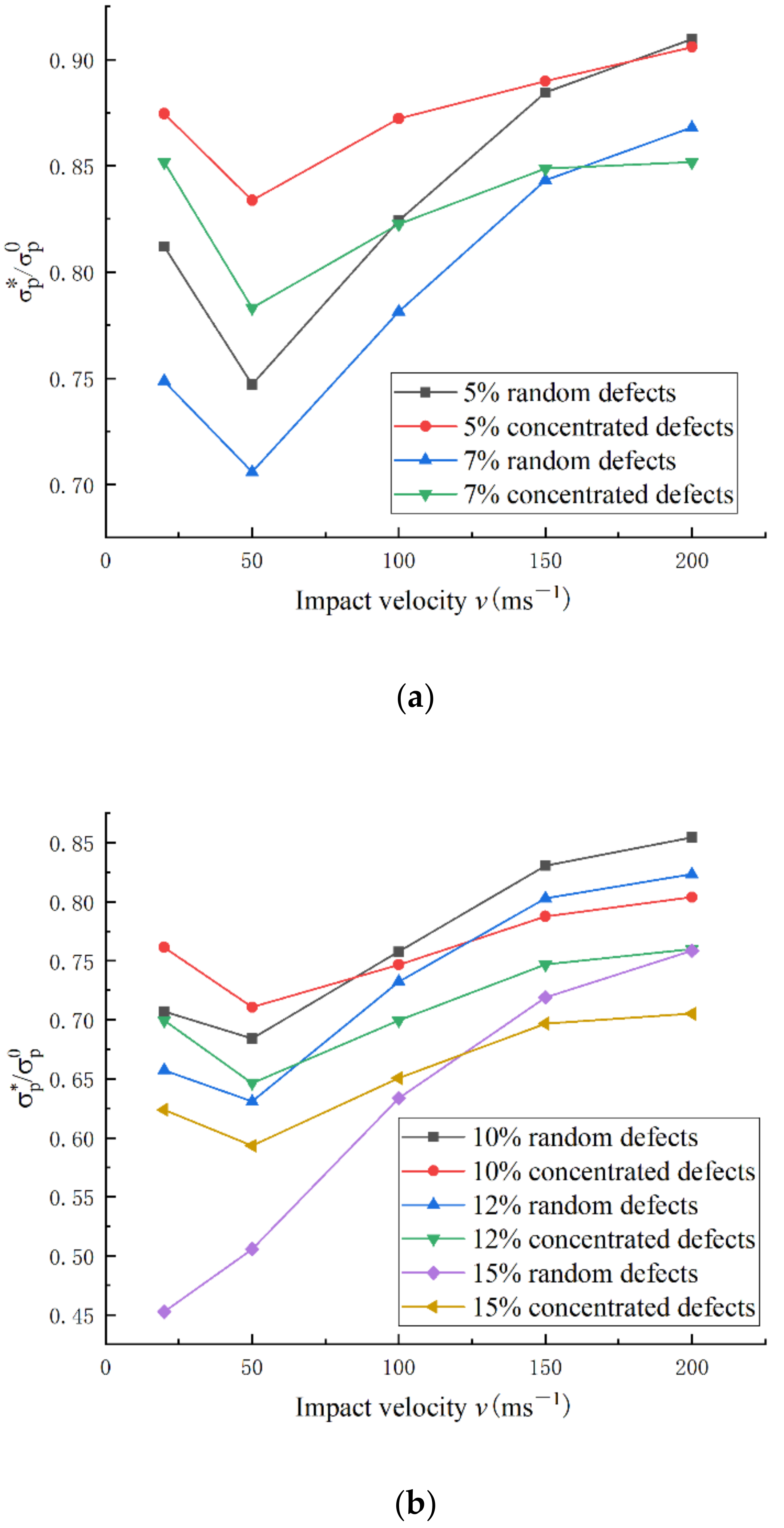
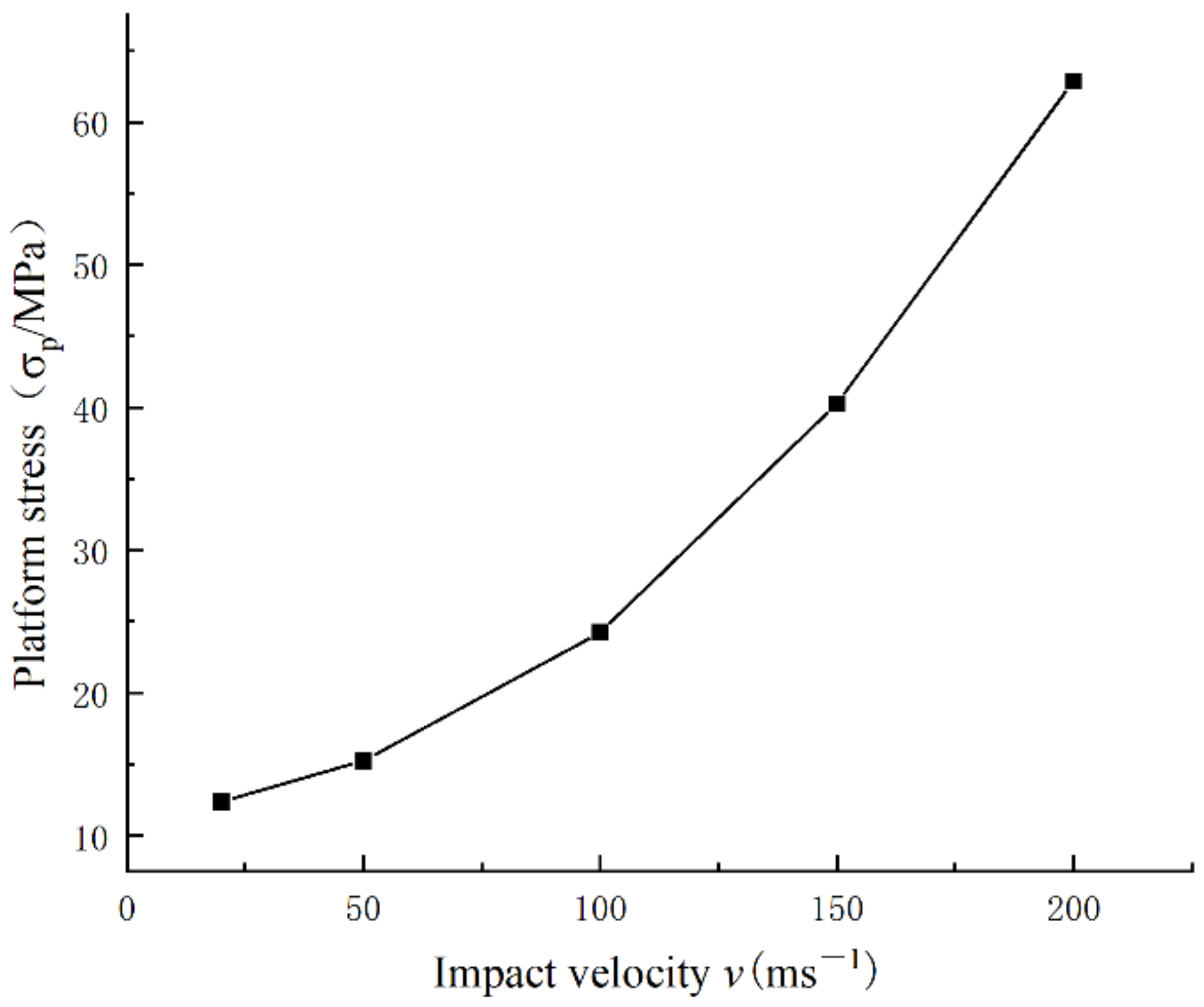
3.4.1. Influence of Impact Velocity on Platform Stress

Figure 12 shows the effect of impact velocity on the platform stress of the defect-free six-ligament chiral structure. It can be seen in the figure that when the impact velocity was in the range of 20–200 m/s, the impact velocity increased. The corresponding platform stress also increased, and the magnitude of the increase in the platform stress also increased.

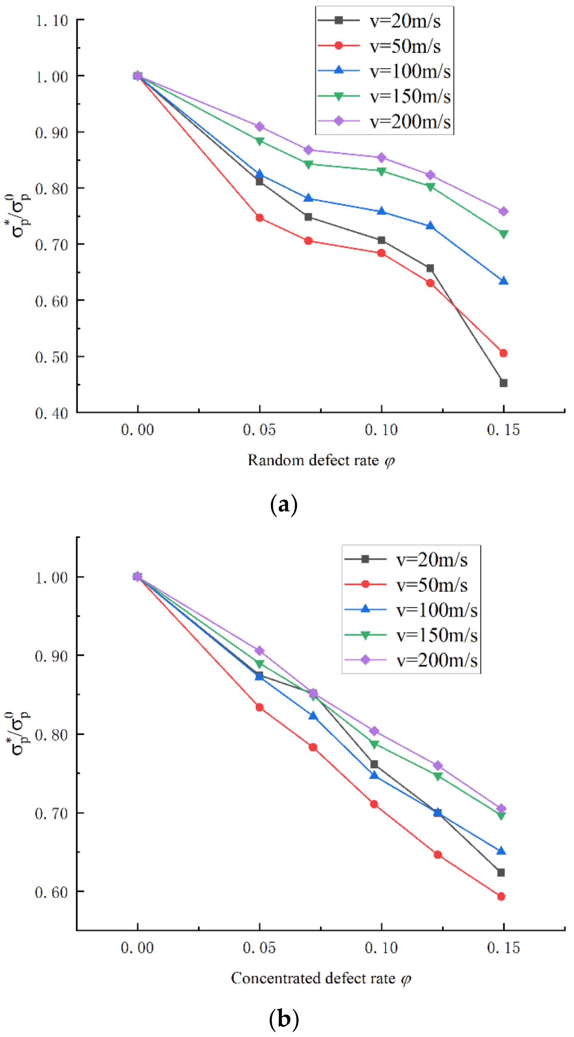
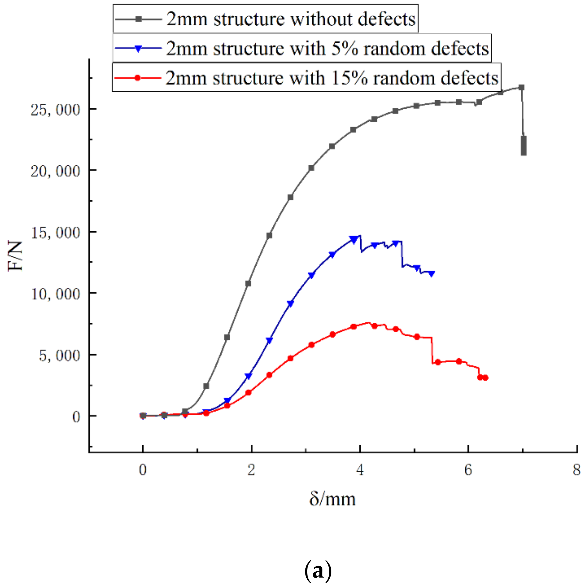
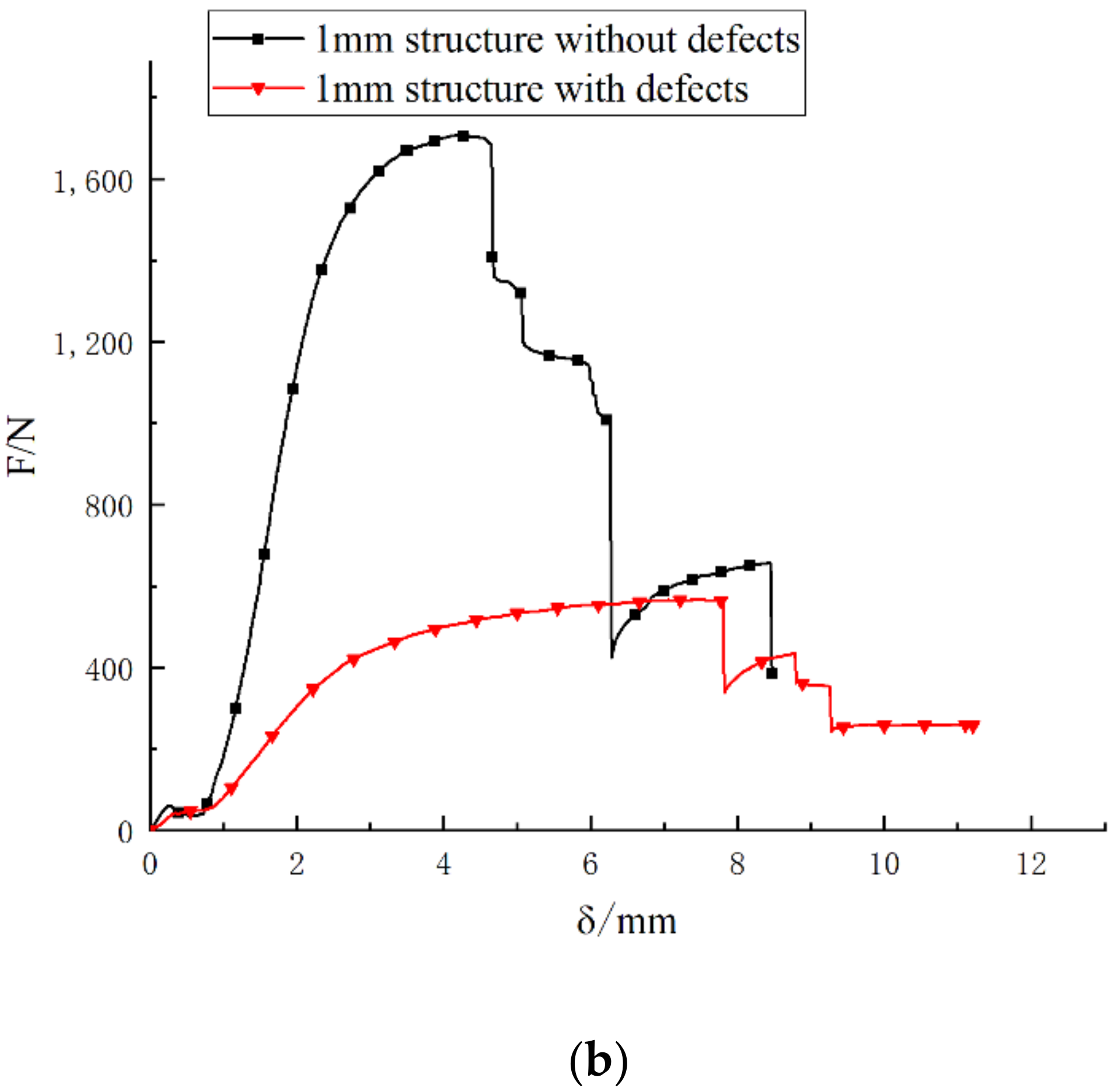
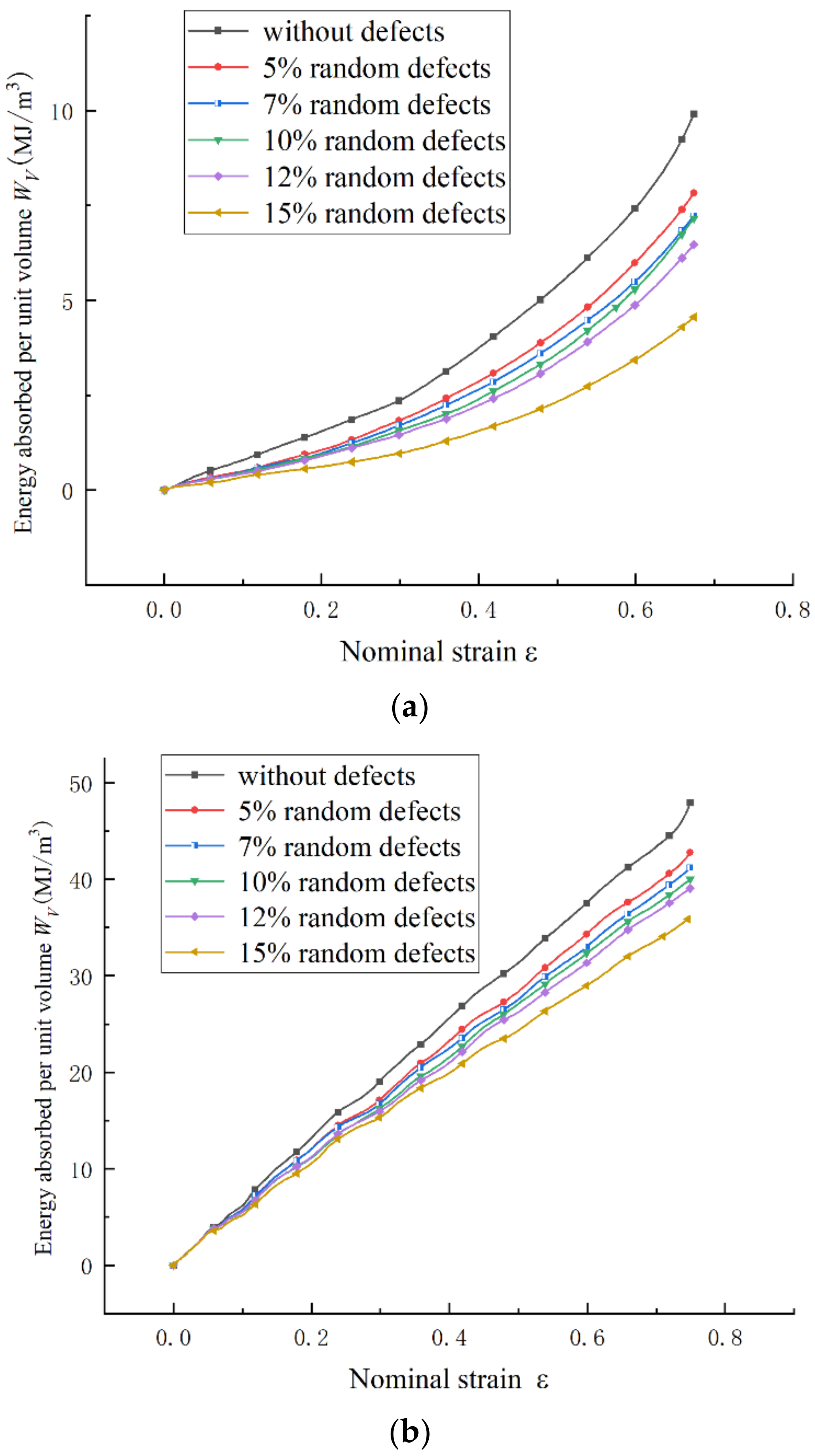
3.4.2. Influence of Defect Rate on Platform Stress

Figure 13a shows the influence of the defect rate on the platform stress when the chiral structure of the six ligaments had random defects. Under the impact speed, the existence of random defects had a significant impact on the plateau stress, and with the increase in the defect rate, the plateau stress showed a decreasing trend. With a defect rate of 5–10%, the trend of the curve was relatively flat, indicating that the increase in the defect rate had less influence on the platform stress. When the defect rates were in the range of 0–5% and 10–15%, the trend of the curve was steeper, indicating that the increase in the defect rate had a significant impact on the platform stress. The calculation results also showed that different impact velocities had different effects on the platform stress. The impact speed was in the range of 50–200 m/s, that is, in the medium-high speed stage. With the increase in the impact speed, the influence of random defects on the platform stress was reduced, mainly because the influence of the inertia effect was enhanced. When the impact speed was 20 m/s at the low-speed stage, when the structural defect rate was in the range of 0–12%, the influence of the defect rate on the stress of the platform was between the two curves of 50 m/s and 100 m/s, indicating that the ligament was wound at this time. The geometrical toughening effect of the structure was strong. When the defect rate of the structure increased to 15%, the platform stress decreased rapidly to 0.45, which greatly reduced the energy absorption capacity of the structure.
Figure 13b shows the effect of the defect rate on the stress of the platform when the six-ligament chiral structure had concentrated defects. Under the impact speed, the existence of concentrated defects also had a significant impact on the plateau stress. With the increase in the defect rate, the plateau stress also showed a decreasing trend. When the impact speed was 50–200 m/s at the medium-high speed stage, the curves all showed a downward trend and the declines were roughly the same. When the impact speed was 200 m/s under the same defect rate, the impact on the platform stress was the smallest. When the impact speed was 50 m/s, the influence on the platform stress was the greatest. However, when the impact speed was 20 m/s, at the low-speed stage, the influence of the defect rate on the platform stress fluctuated greatly, and the range was between the two curves of 50 m/s and 200 m/s. The rate of change was very sensitive, and the geometric tempering effect of the ligament wrapping was strong at this time.
Figure 13. (a) The relationship between the platform stress and the random defect rate under different impact speeds; (b) The relationship between the platform stress and the concentrated defect rate under different impact speeds.
Sustainability 14 11432 g013

3.4.3. Influence of Defect Type on Platform Stress

The platform stress of random and concentrated defects are compared in Figure 14a,b under the same defect rate. By analyzing the two curves of platform stress and impact velocity under 5% random defects and 5% concentrated defects, it can be seen that the platform stress first decreased and then increased with the increase in impact velocity. The platform stress was the lowest at 50 m/s, indicating that the existence of defects had a greater impact on the energy absorption characteristics of the structure during medium-speed impact. By comparing the two curves of platform stress and impact velocity under 5% random defects and 5% concentrated defects, it can be seen that the platform stress of the random defects was significantly lower than that of the concentrated defects when the impact speed was 20–150 m/s. This shows that when the defect rate was low, the number of missing ligaments had a greater impact on the platform stress. When the impact speed was 180 m/s, the two curves met at one point. When the impact velocity reached 200 m/s, the platform stress of the random defects exceeded that of the concentrated defects. This shows that random defects could disperse the stress, which is beneficial to the overall deformation and energy absorption of the structure, whereas concentrated defects could easily cause the structure to collapse and fail, reducing the energy absorption capacity.
By comparing several sets of curves with defect rates of 7%, 10%, and 12%, the results were the same as when the defect rate was 5%, and the speed at which the platform stress of random defects exceeded that of concentrated defects decreased. This also shows that, with the increase in the defect rate, the effect of concentrated defects on structural stability became increasingly important. Above and below the defective part, the microstructure could not absorb energy through deformation. It greatly reduced energy absorption efficiency. When the defect rate was large, φ = 15%, the existence of random defects led to a significant reduction in the number of ligaments and only a few ligaments wrapped around to absorb energy during low-speed impact, which significantly reduced the platform stress.
Figure 14. Comparison of platform stress with random defects and concentrated defects at the same defect rate. (a) Defect rate 5–7%; (b) Defect rate 10–15%.
Sustainability 14 11432 g014

3.5. Energy Absorption Efficiency

Figure 15 shows the effects of random and concentrated defects on the energy absorption properties of the six-ligament chiral structure at different impact velocities. The results show that due to the existence of defects, the energy absorption capacity of the six-ligament chiral structure was reduced. For the energy absorbing capacity of the structure with 15% concentrated defects, with the increase in the impact speed, the influences of random and concentrated defects on the energy absorbing capacity of the structure gradually tended to be consistent.

4. Conclusions

Based on the finite element and experimental methods, the effects of defects on the in-plane impact dynamics of the six-ligament chiral structure were studied and the results showed that:
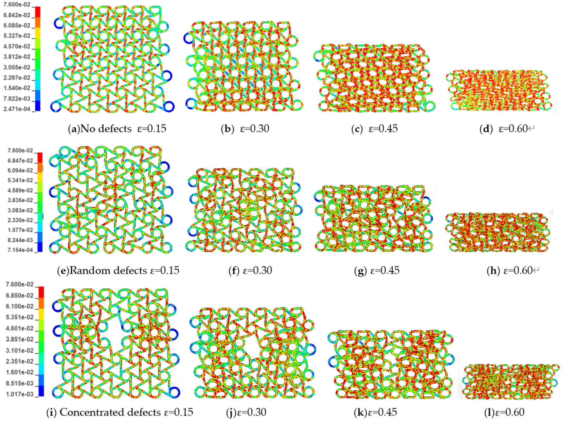
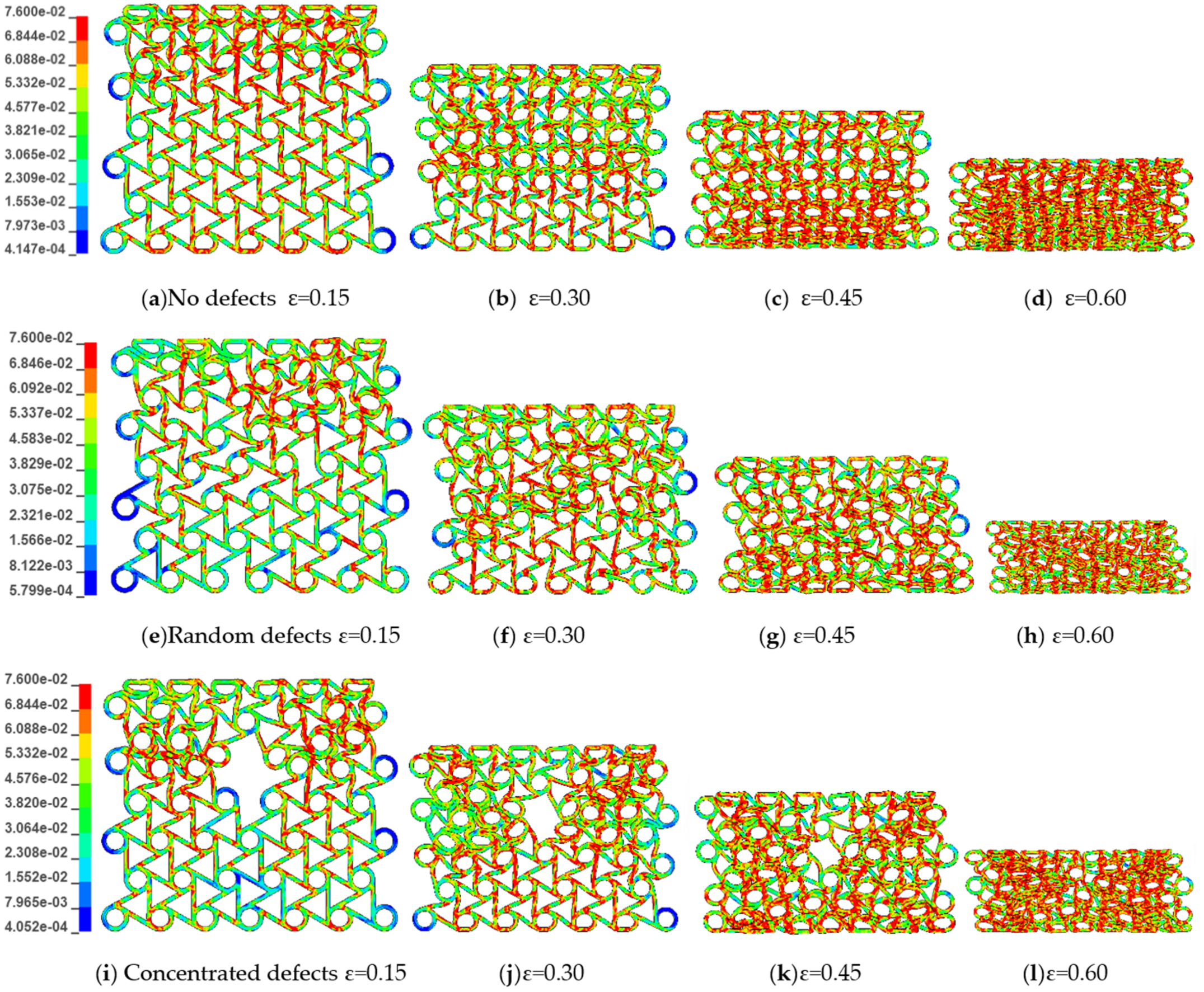
  • Defects have different effects on the macroscopic deformation mode of the six-ligament chiral structure at different impact speeds. During low-velocity impact speeds, ligament wrapping occurs first at the site of the defect throughout the structure. During moderate impact speeds, ligament wrapping occurs both near the impact end and at the defect site. During high-speed impact, the existence of defects does not significantly change the deformation mode of the six-ligament chiral structure, and node crushing and ligament winding are gradually transmitted from the impact end to the fixed end.
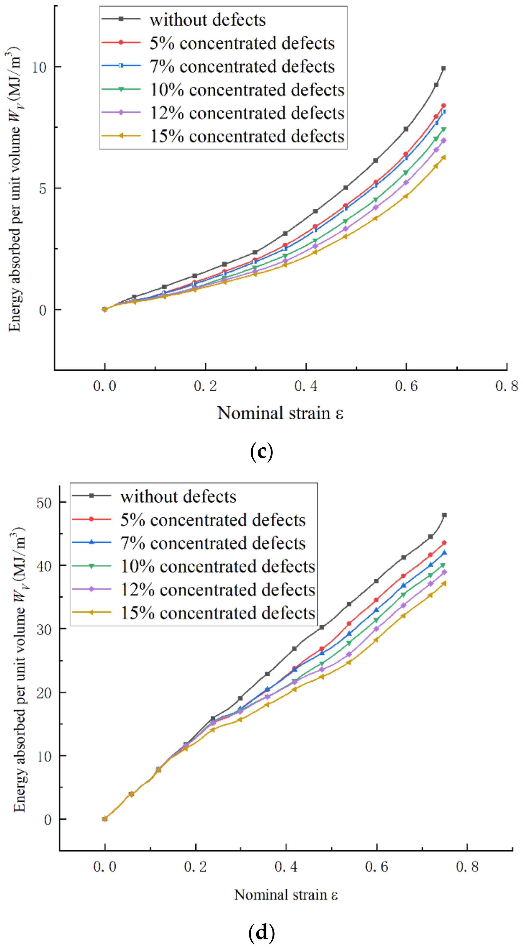
  • The defect will significantly reduce the platform stress and energy absorption capacity of the six-ligament chiral structure. The plateau stress decreases as the defect rate increases. However, random and concentrated defects have different downward trends. During medium- and high-speed impact speeds, with the increase in the impact speed, the weakening effect of defects on platform stress gradually weakens. However, in a low-speed impact, the weakening effect of the defect on the platform stress is higher than that in a medium-speed impact of 50 m/s. As the defect rate increases, the energy absorption capacity of the structure decreases. During a low-speed impact, a higher random defects rate has a greater impact on the energy absorption capacity of the structure than concentrated defects. With the increase in the impact speed, the effects of random and concentrated defects on the energy absorption capacity of the structure gradually increase.
The study of defects is of great significance for realizing the recycling and sustainable utilization of materials. Through research, it is possible to understand the extent to which defects affect structures. If the defective structure meets performance requirements, there is no need to replace it. If the structure fails due to defects during use, it can be applied to fields or components with lower performance requirements, thereby realizing recycling. However, the types of defects studied are limited in this paper and ligament ruptures may occur during use. The effect of the defect location also needs to be further studied. In addition, the large-scale fabrication of metamaterials is a major challenge, limiting the further use of auxetic materials.

Author Contributions

Conceptualization, N.A. and X.S.; methodology, N.A.; software, N.A.; validation, N.A.; formal analysis, N.A.; investigation, N.A.; resources, N.A.; data curation, N.A.; writing—original draft preparation, N.A.; writing—review and editing, N.A., X.S., D.Z. and M.M.T.; visualization, N.A.; supervision, X.S.; project administration, X.S.; funding acquisition, X.S. All authors have read and agreed to the published version of the manuscript.

Funding

The article was supported by the Fundamental Research Funds for the Central Universities (No. 2019ZY15).

Institutional Review Board Statement

Not applicable.

Informed Consent Statement

Not applicable.

Data Availability Statement

Not applicable.

Conflicts of Interest

The authors declare no conflict of interest.

References

  1. Tiju, T.; Gaurav, T. Crushing behavior of honeycomb structure: A review. Int. J. Crashworthiness 2019, 24, 555–579. [Google Scholar]
  2. Sri, D.R.; Manoj, P.; Ratna, K.A. Dynamic compressive behaviour of auxetic and non-auxetic hexagonal honeycombs with entrapped gas. Int. J. Impact Eng. 2020, 146, 103718. [Google Scholar]
  3. Lu, Z.-X.; Wu, W.-B. Numerical simulations for the in-plane dynamic crushing of honeycomb material with negative Poisson’s ratio based on rotating triangle model. Acta Armamentar II 2018, 39, 153–160. (In Chinese) [Google Scholar]
  4. Zhang, X.-C.; Shen, Z.-F.; Wu, H.-X.; Bai, J.-P.; Cao, Y.-P. Study on dynamic response characteristics of multi-segment filled composite honeycombs. J. Hunan Univ. Nat. Sci. 2020, 47, 67–75. (In Chinese) [Google Scholar]
  5. Shen, Z.-F.; Zhang, X.-C.; Bai, J.-P.; Wu, H.X. Dynamic response characteristics of re-entrant circular honeycombs with negative Poisson’s ratio. J. Vib. Shock. 2020, 39, 89–95. (In Chinese) [Google Scholar]
  6. Liu, Y.; Hao, Q.; Tian, Y.-N.; Cui, H.W. Study on structure of negative Poisson’s ratio gradient honeycomb. J. Hubei Univ. Automot. Technol. 2020, 34, 64–68. (In Chinese) [Google Scholar]
  7. Wu, H.-X.; Liu, Y.; Zhang, X.-C.; Yang, S.; Sun, Q.S. Effects of distribution of microstructure types on the in-Plane dynamic crushing of composite honeycomb structures. J. Mater. Eng. Perform. 2021, 30, 850–861. [Google Scholar] [CrossRef]
  8. Wu, W.-W.; Hu, W.-X.; Qian, G. Mechanical design and multifunctional applications of chiral mechanical metamaterials: A review. Mater. Des. 2019, 180, 107950. [Google Scholar] [CrossRef]
  9. Wu, W.-W.; Tao, Y.; Xia, Y.; Chen, J.; Lei, H.; Sun, L.; Fang, D. Mechanical properties of hierarchical anti-tetrachiral metastructures. Extrem. Mech. Lett. 2017, 16, 18–32. [Google Scholar] [CrossRef]
  10. Qian, J.-C.; Cheng, Y.-S.; Zhang, A.-F.; Zhou, Q.; Zhang, J. Optimization design of metamaterial vibration isolator. Struct. Multidiscip. Optim. 2021, 64, 423–439. [Google Scholar] [CrossRef]
  11. Luo, C.; Han, C.-Z.; Zhang, X.-Y.; Zhang, X.G.; Ren, X.; Xie, Y.M. Design, manufacturing and applications of auxetic tubular structures: A review. Thin-Walled Struct. 2021, 163, 107682. [Google Scholar] [CrossRef]
  12. Liu, R.-Y.; Yao, G.-F.; Xu, Z.-Z.; Yu, Z.; Zhang, Z.; Han, C.; Li, H.; Jiang, S. Study on quasi-static mechanical properties of novel reentrant structures with multiple energy dissipation. Thin-Walled Struct. 2022, 177, 109442. [Google Scholar] [CrossRef]
  13. Meng, L.; Shi, J.-X.; Yang, C.; Gao, T.; Hou, Y.; Song, L.; Gu, D.; Zhu, J.; Breitkopf, P.; Zhang, W. An emerging class of hyperbolic lattice exhibiting tunable elastic properties and impact absorption through chiral twisting. Extrem. Mech. Lett. 2020, 40, 100869. [Google Scholar] [CrossRef]
  14. Novak, N.; Vesebjak, M.; Tanak, S. Compressive behaviour of chiral auxetic cellular structures at different strain rates. Int. J. Impact Eng. 2020, 141, 103566. [Google Scholar] [CrossRef]
  15. Novak, N.; Mauko, A.; Ulbin, M. Development and characterisation of novel three-dimensional axisymmetric chiral auxetic structures. J. Mater. Res. Technol. 2022, 17, 2701–2713. [Google Scholar] [CrossRef]
  16. Zhang, X.-C.; Zhu, X.-N.; Li, N. A study of the dynamic response characteristics of hexagonal chiral honeycombs. J. Vib. Shock. 2016, 35, 1–7. (In Chinese) [Google Scholar]
  17. Qi, D.-X.; Lu, Q.-Y.; He, C.-W.; Li, Y.; Wu, W.; Xiao, D. Impact energy absorption of functionally graded chiral honeycomb structures. Extrem. Mech. Lett. 2019, 32, 100568. [Google Scholar] [CrossRef]
  18. Su, X.W.; Zhu, D.M.; Zheng, C.; Tomovic, M.M. Mechanical properties of 65 Mn chiral structure with three ligaments. J. Mech. Engl. Ed. 2019, 35, 88–98. [Google Scholar]
  19. Mauko, A.; Fíla, T.; Falta, J. Dynamic deformation behaviour of chiral auxetic lattices at low and high strain-rates. Metals 2021, 11, 52. [Google Scholar] [CrossRef]
  20. Liu, K.; Gao, X.-F.; Zhang, P. Dynamic mechanical performances of enhanced anti-tetra-chiral structure with rolled cross-section ligaments under impact loading. Int. J. Impact Eng. 2022, 166, 104204. [Google Scholar]
  21. Liu, W.-D.; Yang, Z.-D.; Du, S.; Li, H.; Zhang, Q. Theoretical, numerical and experimental study on the in-plane elastic behavior of a 2D chiral cellular structure. Compos. Struct. 2022, 296, 115889. [Google Scholar] [CrossRef]
  22. Wu, W.-W.; Qi, D.-X.; Liao, H.-T.; Qian, G.; Geng, L.; Niu, Y.; Liang, J. Deformation mechanism of innovative 3D chiral metamaterials. Sci. Rep. 2018, 8, 12575. [Google Scholar] [CrossRef] [PubMed]
  23. Attard, D.; Farrugia, P.S.; Gatt, R.; Grima, J.N. Starchirals—A novel class of auxetic hierarchal structures. Int. J. Mech. Sci. 2020, 179, 105631. [Google Scholar] [CrossRef]
  24. Li, K.Y.; Zhang, Y.; Su, L.; Duan, N.; Shi, W. Crushing mechanics of anti-tetrachiral column. Thin-Walled Struct. 2022, 175, 109253. [Google Scholar] [CrossRef]
  25. Lu, Q.Y.; Qi, D.X.; Li, Y.; Xiao, D.; Wu, W. Impact energy absorption performances of ordinary and hierarchical chiral structures. Thin-Walled Struct. 2019, 140, 495–505. [Google Scholar] [CrossRef]
  26. Airoldi, A.; Novak, N.; Sgobba, F. Foam-filled energy absorbers with auxetic behaviour for localized impacts. Mater. Sci. Eng. A 2020, 788, 139500. [Google Scholar] [CrossRef]
  27. Qiu, K.-P.; Wang, R.-Y.; Zhu, J.-H.; Zhang, W. Optimization design of chiral hexagonal honeycombs with prescribed elastic properties under large deformation. Chin. J. Aeronaut. 2020, 33, 902–909. [Google Scholar] [CrossRef]
  28. Gao, D.-W.; Wang, S.-H.; Zhang, M.-Z.; Zhang, C. Experimental and numerical investigation on in-plane impact behaviour of chiral auxetic structure. Compos. Struct. 2021, 267, 113922. [Google Scholar] [CrossRef]
  29. Xin, X.; Liu, L.; Liu, Y.; Leng, J. 4D Printing auxetic metamaterials with tunable, programmable, and reconfigurable mechanical properties. Adv. Funct. Mater. 2020, 30, 2004226. [Google Scholar] [CrossRef]
  30. Fernandez-Corbaton, I.; Rockstuhl, C.; Ziemke, P.; Gumbsch, P.; Albiez, A.; Schwaiger, R.; Frenzel, T.; Kadic, M.; Wegener, M. New twists of 3D chiral metamaterials. Adv. Mater. 2019, 31, 1807742. [Google Scholar] [CrossRef]
  31. Zhang, Z.-J.; Long, Y.-H.; Xu, R.-W.; Liu, Q.-Y.; Zhou, L.; Huang, P.; Lan, G.-Q. Research progress and prospect of additive manufacturing technology forming mechanical meta-materials. Mach. Tool Hydraul. 2022, 50, 151–158. (In Chinese) [Google Scholar]
  32. Yoon, G.H.; Kim, I.K.; Rho, J.S. Challenges in fabrication towards realization of practical metamaterials. Microelectron. Eng. 2016, 163, 7–20. [Google Scholar] [CrossRef]
  33. Hu, J.; Ren, J.W.; Ma, W.; Liu, J.H.; Wang, A.G. Dynamic performances of graded honeycomb materials containing random defects under impact loading. Mater. Rep. 2019, 33, 2777–2784. (In Chinese) [Google Scholar]
  34. Liu, Y.; Zhang, X.-C. Effects of inhomogeneous distribution of defects on in-plane dynamic properties of honeycombs. Explos. Shock. Waves 2009, 29, 237–242. (In Chinese) [Google Scholar]
  35. He, Q.; Feng, J.; Zhou, H.-G.; Tian, G. Numerical study on the dynamic behavior of circular honeycomb structure with concentrated filling inclusions defects. J. Mech. Sci. Technol. 2018, 32, 3727–3735. [Google Scholar] [CrossRef]
  36. Sri, D.R.; Manoj, P.; Ratna, K.A. Effect of defects on the dynamic compressive behavior of cellular solids. Int. J. Mech. Sci. 2019, 170, 105365. [Google Scholar]
  37. Esa, M.; Xue, P.; Zahran, M.; Abdelwahab, M.; Khalil, M. Novel strategy using crash tubes adaptor for damage levels manipulation and total weight reduction. Thin-Walled Struct. 2017, 111, 176–188. [Google Scholar] [CrossRef]
  38. Long, S.; Yao, X.; Zhang, X. Delamination prediction in composite laminates under low-velocity impact. Compos. Struct. 2015, 132, 290–298. [Google Scholar] [CrossRef]
Figure 1. Test setup. (a) Test machine; (b) Experimental model.
Sustainability 14 11432 g001
Figure 2. (a) Simulation model of the six-ligament chiral structure; (b) Meshing diagram.
Sustainability 14 11432 g002
Figure 3. (a) Six-ligament chiral structure model with 5% random defects; (b) Six-ligament chiral structure model with 5% concentrated defects.
Sustainability 14 11432 g003
Figure 4. (a) Force–displacement curve of six-ligament chiral structure (b) The kinetic energy and internal energy change curves of the model.
Sustainability 14 11432 g004
Figure 5. Effect of mesh length on platform stress and calculation time.
Sustainability 14 11432 g005
Figure 6. Failure mode of the structure (a) Structure with no defects; (b)Structure with 5% defects; (c) Structure with 15% defects.
Sustainability 14 11432 g006
Figure 7. Quasi-static compressive force–displacement curve. (a) Six-ligament chiral structure; (b) Cell structure.
Sustainability 14 11432 g007aSustainability 14 11432 g007b
Figure 8. Quasi-static loading test images of the cell structure. (a) Loading diagram of the structure without defects; (b) Undefective cell structure; (c) Failure diagram after loading; (d) Loading diagram of the structure with missing ligaments; (e) Structure diagram with defects; (f) Destruction diagram after loading.
Sustainability 14 11432 g008aSustainability 14 11432 g008b
Figure 12. The relationship between the platform stress and impact velocity of the six-ligament chiral structure with no defects.
Sustainability 14 11432 g012
Figure 15. Energy absorption characteristics of structures with defects at different impact velocities. (a) v = 20 m/s random defects; (b) v = 200 m/s random defects; (c) v = 20 m/s concentrated defects; (d) v = 200 m/s concentrated defects.
Sustainability 14 11432 g015aSustainability 14 11432 g015b
Publisher’s Note: MDPI stays neutral with regard to jurisdictional claims in published maps and institutional affiliations.

