The following results report the experiments conducted in the case study to explain what UAS can provide to project management, and how the data generated are integrated into the existing project management system.
3.1. Site Planning
Traditionally, project managers in the preconstruction stages use satellite photos or the surveyor’s plan to map the site layout. Using an UAS as an alternative tool provides a 3D site map and videos with high accuracy and better resolution [
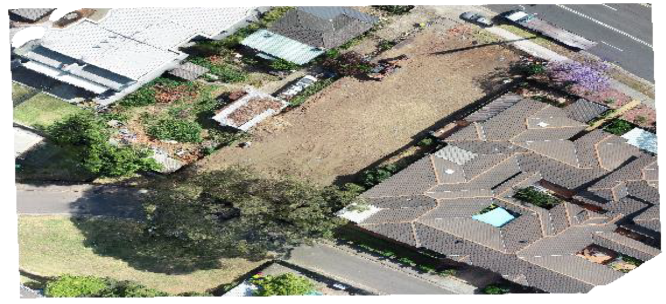
8]. In urban districts with smaller and congested lots, the high maneuverability of the UAS is an advantage. Project managers used the 3D point cloud of the site generated by the UAS to visualize the site layouts better than the traditional method and measure distances and height differences between various points on site. In the project presented in this work, the existing site layout and elements were first collected using an UAS. The example provided in
Figure 4 shows site vegetation color coded in brown.
Site planning covers most of the building activities, including planning the site layout for material handling, locating the storage areas for delivered materials, site administration offices, crane positions (if any), site egresses, and site monitoring tools required during the construction stage [
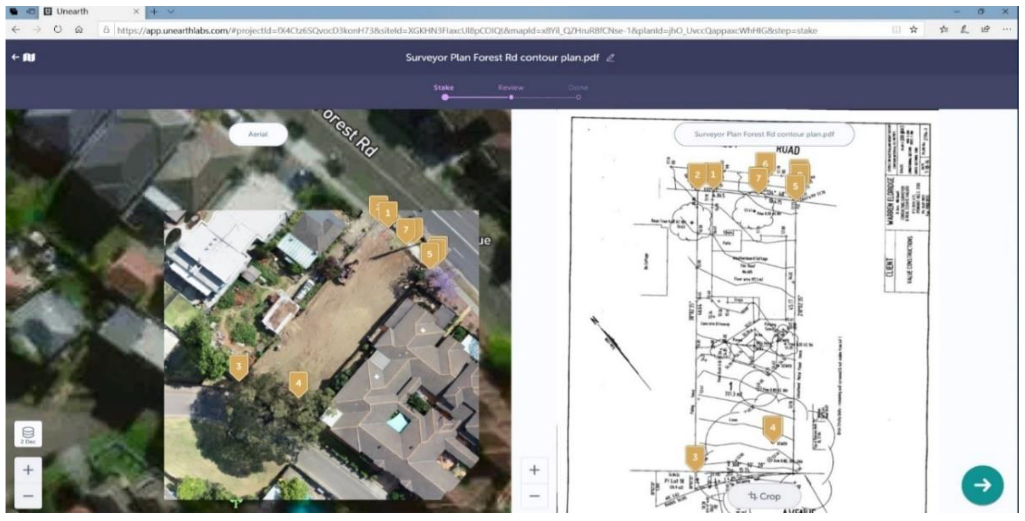
9]. As displayed in
Figure 5, the UAS provided accurate special data at a much cheaper cost and in a shorter time than the conventional tools used by surveyors. The 3D map facilitated a clear image of the site and its surroundings and enabled the users to check the distances, dimensions, or heights of the surrounding buildings. As confirmed by the project’s architect, the map provided a clear vision of the site context, which surveyor plans and satellite aerial photos could not address. Satellite image resolution and accuracy varies according to the use of the images. The most commonly used resolution is 5 m. Higher resolutions of up to 30 cm are available to the public at a cost. This level of resolution means any object less than 30 cm blends into its surroundings and the details of that object will not be distinguishable [
10]. UAS images using RTK or PPK equipment have a higher resolution and accuracy, with a 2 cm relative vertical accuracy and a 1.2 cm relative horizontal accuracy [
11,
12].
3.2. Assets Inspection
The deployment of UASs for asset inspection is not unprecedented. Bridges, communication towers, and powerlines are a few to mention. Historical buildings and construction inspections were also conducted using UASs [
13]. As indicated by an industry expert, “the photos taken by the UAS are real-time footage and very clear, which will be sent to engineers or project stakeholders for comments or action. This reduces time, cost and risk involved in traditional visual inspection.” An example of the efficiency of the UAS in asset inspection was provided by the National Drones, whose inspections of 150 schools across rural NSW including 1200 buildings were carried out in 40 days [
14]. The inspections were intended to determine the roof conditions of the schools for maintenance planning. The safety as well as the time and costs saved of the asset inspection using the UAS were reported to be substantial [
14].
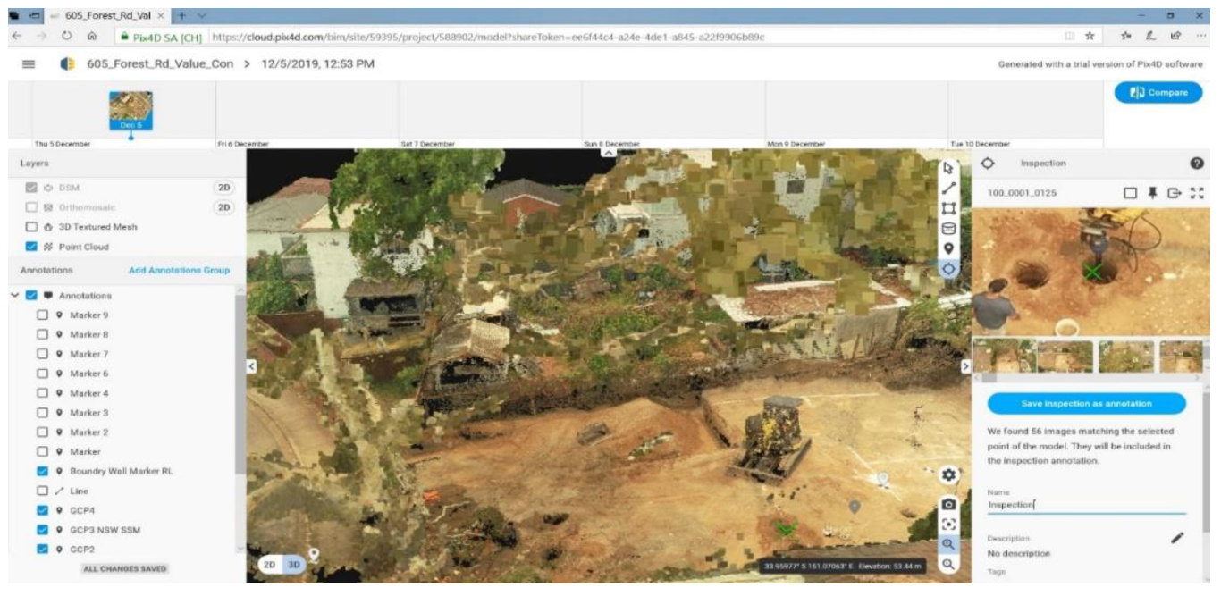
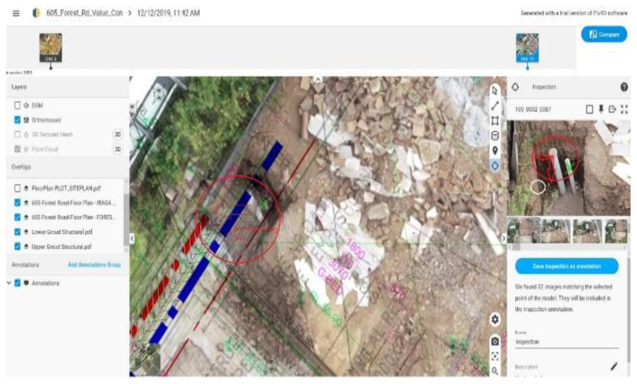
In our case study, the data collected using UAS were used to virtually inspect the work performed, as shown in
Figure 6. The 3D aerial map provided could be zoomed in at any point for inspection purposes to monitor work progress. This allowed the project personnel to inspect in detail the work performed without physically stepping foot on the site. The zoomed-in images were in high resolution and showed even the tiniest details. The site management team confirmed that this feature added great value to site supervision and the quality of work performed.
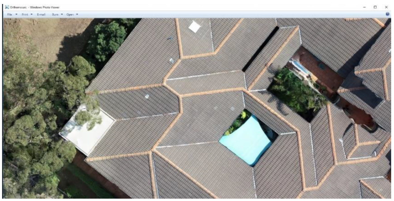
In another example demonstrated in
Figure 7, a roof inspection was conducted risk-free. The project manager used the provided information to check roof conditions for maintenance at the post-construction stage without using cherry pickers or erecting scaffolding.
3.3. Bulk Excavations Monitoring and Measurement
Bulk excavations within construction sites are conventionally conducted with a surveyor marking the level of the area to be excavated on the ground for the excavator to proceed with the operation. The surveyor, from time to time, returns to the site to check the area and the levels excavated. By using the 3D terrain model taken by the UAS, in the presented case study, there was no need for the surveyor to mark the level or the area on the ground. The project manager, using the 3D terrain model data generated by the UAS, which was overlayed by the architectural or engineering plan, marked the levels and the area to be excavated. As the work progressed, the UAS regularly flied over the excavated areas and generated an updated 3D terrain model. This allowed the project manager to monitor and check the levels of the excavated areas and whether they matched the design plans. The volume of soil excavated was also calculated almost immediately.
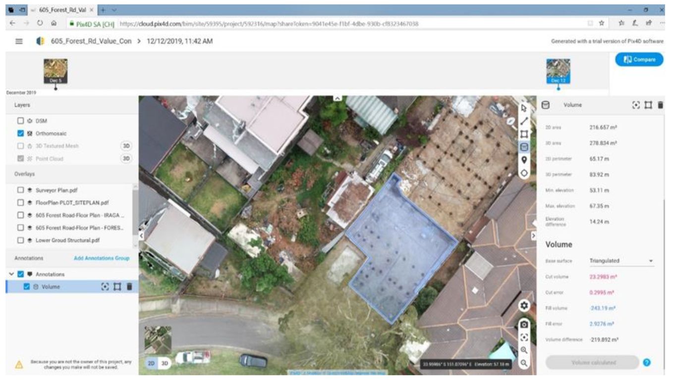
The photogrammetry software platform Pix4D, as shown in
Figure 8, enabled the project manager to work out the volume of the excavated soil in the designated areas. The volume calculated is shown in negative figures because the area excavated is below the surface level. The level of accuracy obtained is between 15 mm vertically and 20 mm horizontally, which is very high for a typical, large-sized area [
15]. The comparison between the traditional surveying method and the deployment of the UAS showed the efficiency of the UAS for measuring the bulk excavation.
3.4. Work Quality and Control
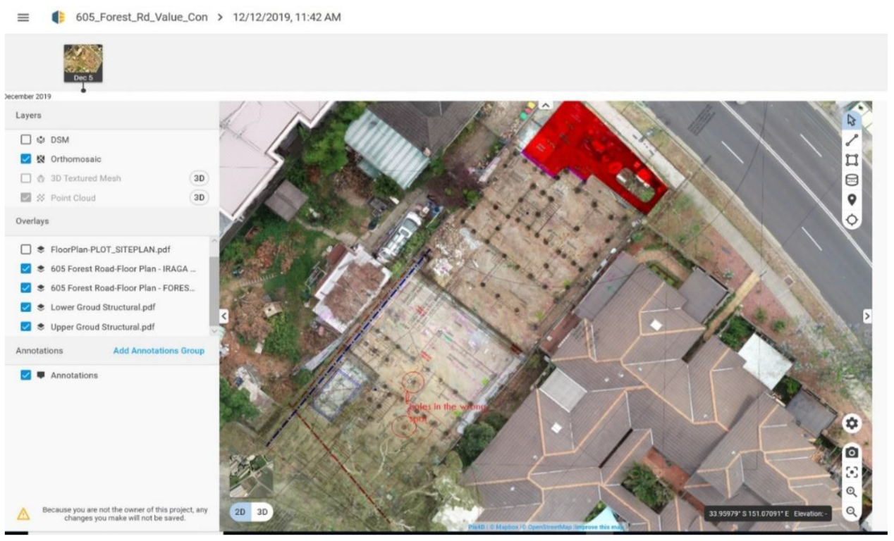
Three major suppliers of UAS data processing solutions expressed in their discussions with the research team that the existing digital platforms were not designed to be used for construction management. It was indicated that checking measurement accuracy for the work performed at construction sites is a new task for the sector. The extent of the existing platforms was explained to be mostly limited to surveying. Accuracy checks are new features that are required to be added to the platforms to better align them with construction management purposes. An example from the case study is provided in
Figure 9. The surveying, engineering, and floor plans were inserted as layers on the 3D site map. Then the position and level of the building elements were controlled and compared against the design plans. The discrepancies were identified and reported to the project manager to address. The information was also forwarded to the design engineer and the client who requested rectification. The project manager appreciated the early identification of the problematic piers to avoid costly repairs and potential delays in the future. As a comparison, it would cost approximately AUD 900 for a surveyor to check the piers and levels on site, and the task might take up to two weeks to complete. This contrasts with the work that used the UAV, which was completed in two days with a cost of AUD 400.
If the work had proceeded without discovering the problem, then extra time and materials would have been needed to rectify the work. This would involve concrete cutting and breaking of the slab to reinstate the piers in the right place, producing extra waste. Discovering defects at an early stage during construction reduces the amount of wastage and pollution, which could occur if the rectification was to be performed at a later stage during construction.
Another opportunity for avoiding unnecessary waste production created by the USA data was the record of the services’ location. As shown in
Figure 10, the location of services can be identified at any time when needed to avoid damages through the operation of other trades.
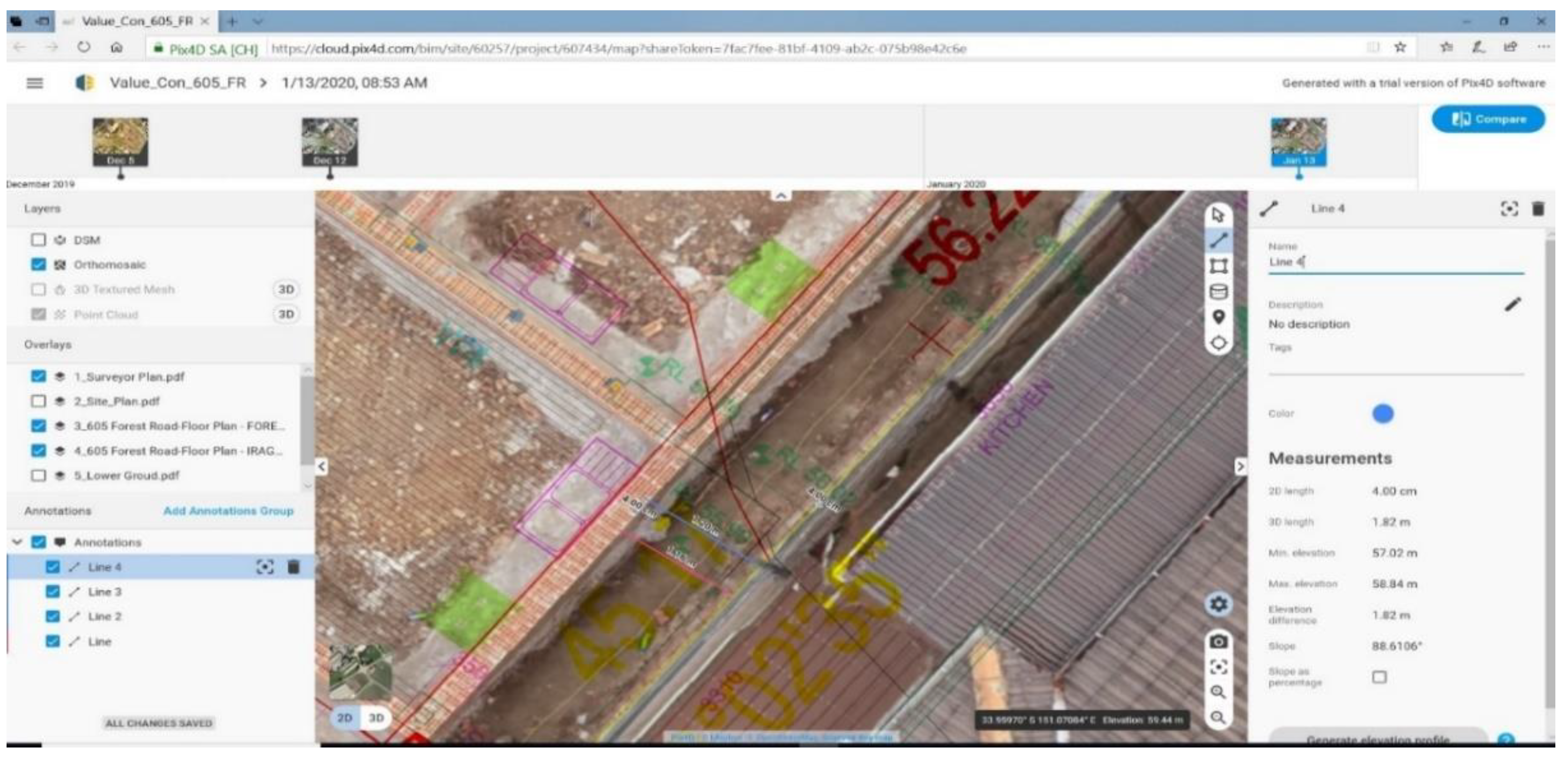
Brick walls were used to estimate systems accuracy and calibration. The surveyor marked the GCP as a reference point to match the orthomosaic plan with the accurate as-built drawings. As shown in
Figure 11, a discrepancy of 2 cm to 4 cm between the UAS measurement and the actual work was detected. This accuracy is within the range reported in the literature for orthomosaic plans [
16]. This difference is because of the correction errors using RTK (Real Time Kinematic) or PPK (Post Processing Kinematic) systems for satellite coordinates [
17].
Typical land surveying equipment delivers a sub 3 cm relative accuracy in the horizontal direction and a 9cm accuracy in the vertical direction [
12]. In comparison, the Phantom 4 RTK utilized in this study delivered a 2 cm horizontal accuracy and a 2 cm vertical accuracy. The accurate data provided by the UAS allow stakeholders to enhance the analyses of work progress and the effectiveness of their quality control processes. We demonstrated that, like larger projects, such as road construction and mining in which the accurate measurement of earthwork is critical, off-the-shelf UAS products and services are becoming mature enough to be an integral part of the construction supervision and progress monitoring of earthmoving activities.
3.5. Work in Progress Report
A progress report is a document that outlines the progress of work towards the completion of the work [
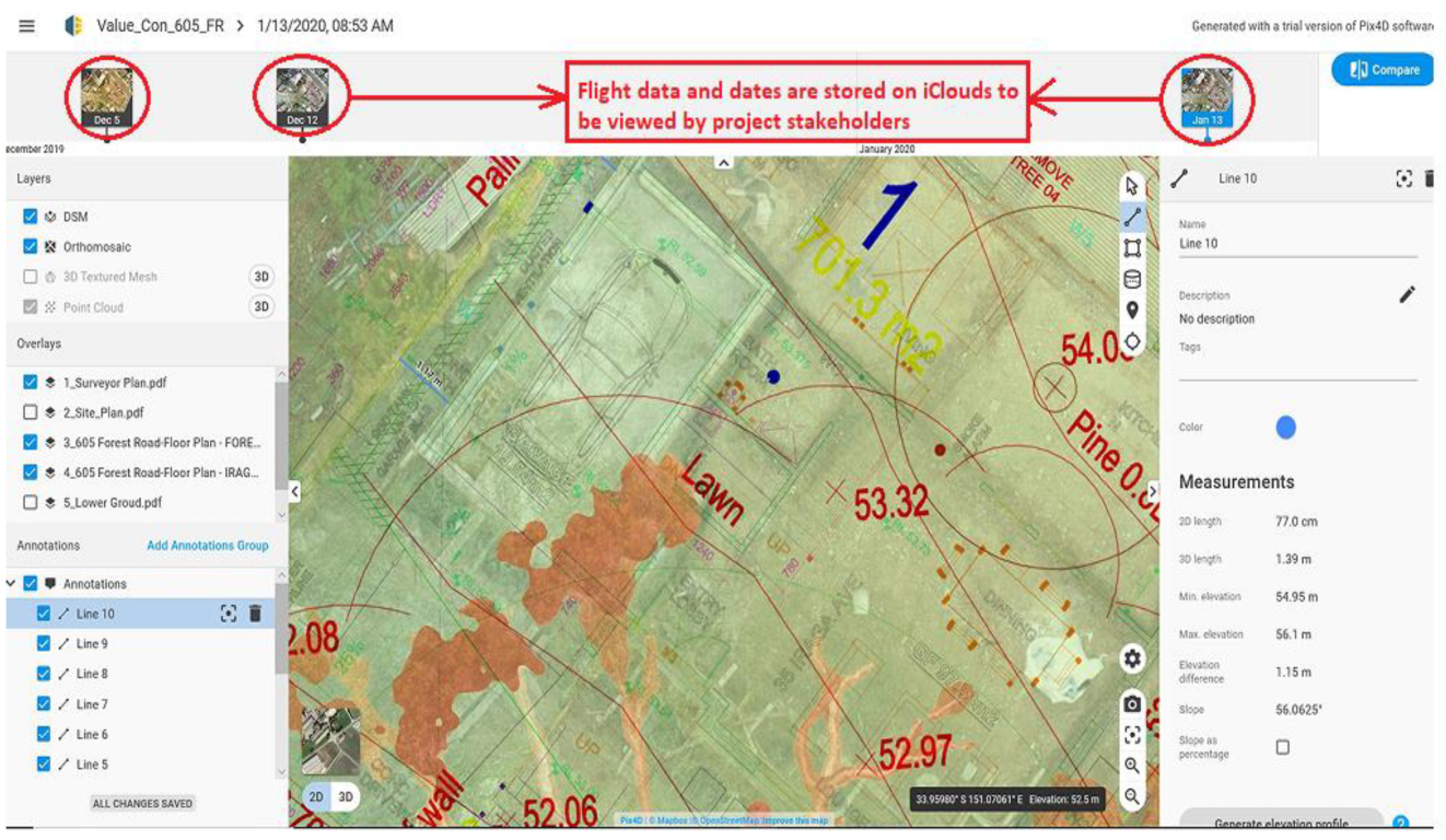
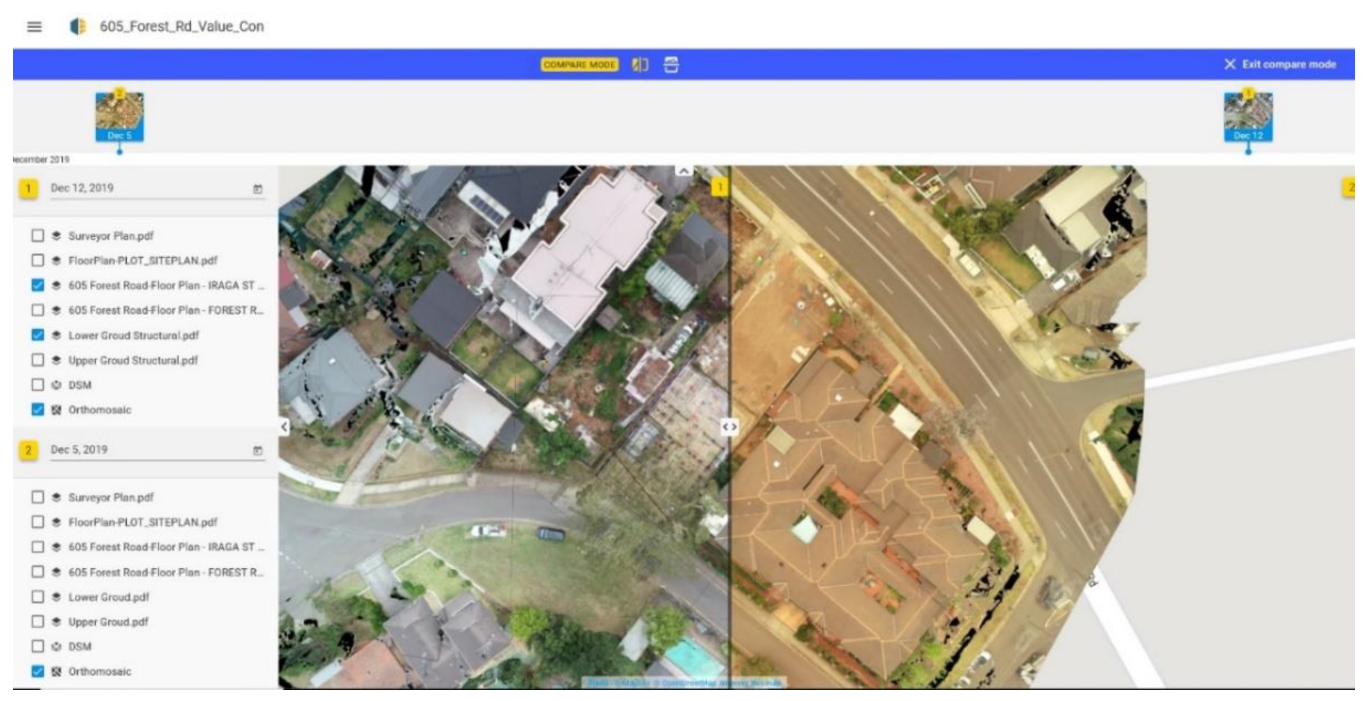
18]. The development of progress reports for record keeping and project monitoring was stated by the project manager of our case study to always be an issue due to the unavailability and lateness of the data. As shown in
Figure 12, the Pix4D platform was utilized in the case study to inform project stakeholders of the progress of the work. The platform was used to generate a progress payment claim to show the client the stage of the work at a certain date, as shown in the top corner of the image (see
Figure 12). It was noted that the sector still has not adopted BIM in their progress claims and progress of work reports, and still relies on project managers’ reports and photos. The client appreciated the facilitated access to the progress of the work.
The UAS was used to the extent that the collected details could verify the claims made by the contractor. The use of the UAS was not intended to replace the standard inspections mandated by the regulations which are carried out by a certified building surveyor. The collected details were mainly used to examine the claims made by the contractor about the stage of the work and the associated cost claims.
The UAS progress report feature did help clients understand the work progress. It provided a clear comparison between the current state of the work and the previously reported stage. This feature enabled the client to be more confident that the progress of work is consistent with the design plans and specifications. The asset library containing the details collected at a specific time provided all the information on the progress of work.
3.6. BIM and UAS in Construction
The construction industry is currently running to embrace emerging technologies by integrating BIM for data management and coordinating all building elements, including planning, design, and construction activities. BIM enables project managers to analyze data in a highly efficient way. The UAS proved, as shown earlier in this paper, to be a very effective tool for collecting real-time data. This data stream has the potential to enrich BIM. By adopting UAS technology to feed to 5D BIM, new functions were added to the model towards the development of a smart construction site. As explained earlier, it allowed project stakeholders not only to visualize the progress of work according to the schedule, but also to check if there are defects and determine the actions required for correcting the defective works. Implementing BIM 5D and the features provided by the UAS to enhance the project management system formed the basis of the development of a smart construction site.
Figure 13 shows how the UAS images were overlayed on a floor plan to check the accuracy of quantity measurement, levels, and quality of work. This is a good example of what could be added to BIM models to obtain a clear picture of the progress of work and the quality and accuracy of the work performed.
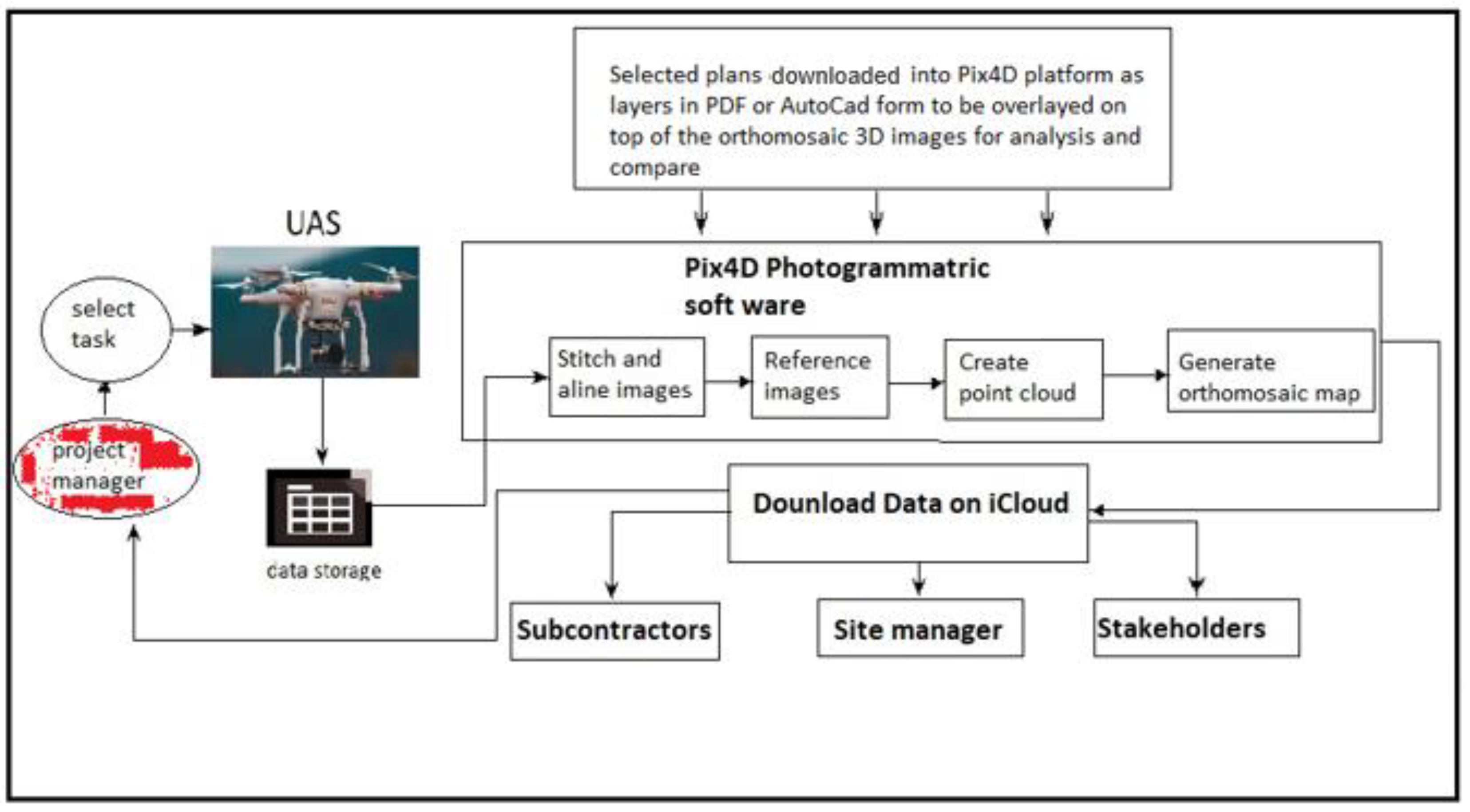
The progress claim is generated through the model to reflect the progress of the accomplished work and the associated cost. At every progress claim, project stakeholders were able to monitor the cash flow and the time progress if it was going according to schedule. To reach the final progress claim stage, the data generated by the BIM for the progress of work have been retrieved as layers to be able to be downloaded and fed into the PIX4D platform. Layers comprising engineering plans, service plans, and architectural plans were separately fed to be able to superimpose with the orthomosaic plan or 3D point cloud generated by the UAS to check the quality and accuracy of the work. After all the layers were checked, the progress claim was generated using the data retrieved from the BIM and the UAS. This enabled project stakeholders to be fully aware of the progress of work and the quality of work performed to avoid mistakes that could have led to extra costs or delays. It was suggested by the project management team of the studied project that the developed system can be referenced and tracked to resolve potential disputes.
The 3D point cloud and 3D image generated by the BIM can be superimposed using the Pix4D software if the same viewpoint is adopted. The most practical way is to use the top view images, then the plans can be superimposed for an accuracy check. There were details that are important but cannot be seen in the top view images. In this case, the visual comparison and check have been performed manually.
3.7. Obstacles in Applying UAS on Site
The research team asked the project management team and tradespersons on site about the impediments to the wider uptake of UASs in smaller scale construction projects. Digital culture, ethical reservations, legal requirements, liability risks, and weather conditions were articulated as the major obstacles to the deployment of the UAS.
Building a smart construction site requires the emergence of a new culture on the site. This is called a digital culture. This culture requires an agile approach and starts by taking incremental steps toward building and applying a data-centric approach for continual improvement. Cultural changes require a few steps to be taken, starting from the administration level down to the workers who perform the task.
The digital culture was mentioned to force project teams to shift from passive data users to more proactive analyzers to improve performance and site safety. Project managers, as the key decision makers in implementing UASs, are required to ensure that the use of technology delivers a positive benefit to all stakeholders.
Ethical issues arise predominantly from the person controlling the UAS. Misuse, operator error, and failure of the machine all result in not only injury to the surrounding people, but also to the buildings and structures themselves within the construction site. Before an individual begins to use the UAS within a construction site, it is necessary that the main objectives on the use of drones are established, such as the type of data that will be retained, the amount of time the data collection will take, and the outline of data applications. It is also essential to analyze the qualification of the persons piloting the UAS and conducting measurements. It is recommended that a set of ethical principles be outlined before using the UAS within construction management. This may eliminate the concern individuals have with certain privacy issues whilst the UAS is in operation collecting the data of bystanders and the public. This can include but is not limited to aerial photographs being taken, or the general surveillance of the site itself.
One of the restricting flight rules is the permissible flight areas map drawn and marked by CASA in Australia, FAA in the US, EASA in EU, or CAA in the UK. The map shows which areas licensed or unlicensed pilots can fly in. The regulators are extremely strict with their rules as they affect the commercial aviation flight paths. For example, in Australia, for pilots who do not obey the rules and regulations, there is a penalty of AUS AUD 1110 per offence, which increases to AUD 11,100 if the offence is referred to court. Offences also could lead to restrictions or the cancellation of the pilot’s accreditation and license.
The deployment of an UAS in the sky to perform a task or collect data is always associated with a level of risk and liability. The level of risk and liability has been assessed in a 2016 survey in the UK to develop the right insurance policies to cover UAS operations. The survey found that the insurance underwriters have not fully understood this industry and its risk [
19]. The risk and liability exposure of these entities is entirely unknown due to the lack of historical data to determine liability triggers and trends to facilitate the development of accurate insurance underwriting [
20]. It was stated by the case study participants that insurance policies are required to cover both the UAS and the equipment attached to it, such as electronic components and the advanced cameras and sensors which could cost up to AUD 500,000.
Weather conditions are mentioned as a critical factor for UAS operation. Wind speed, precipitation, visibility, rain, fog, dust and humidity were listed as the factors the operator should take into account before the flight. Unfortunately, the impact of these factors is not well explained and standardized for this industry to follow. There are a few published standards or specifications available, but from the legal authorities, such as the American National Standard Institute, nothing has been done on this matter yet [
21]. Many manufactures specify the safe operating parameter in their UAS’s manual and expect the UAS operators to follow and apply the parameters specified in these manuals. Some of these parameters are for the UAS operation during rains, fog, wind speed, visibility, etc. The manuals include wind speeds of 10–15 m/s and precipitation thresholds from 0 to 1 mm. Different UASs have different parameters. This depends on the weight of the UAS and its resilience to weather conditions. Figures supplied in UAS manufacturers’ manuals do not refer their data or parameters to any standards, test protocols, or certifications [
22]. This makes these parameters a source of doubt, which triggers legal concerns.
The continuation of the use of UASs for later stages of the project when the majority of the work is conducted in an indoor environment was a reasonable expectation that was identified. This need informs our future work to examine the use of UASs in non-open-air construction environments. The off-the-shelf product shortlisted for asset inspection in enclosed areas is Elios 2. This model is equipped with safeguards, lighting, and sensers to avoid any collisions with the surroundings. It is a small drone 40 cm in diameter. It can be flown into an area where workers cannot access. It operates by a wireless transmission system in situations in which GPS is not available. It provides 2D and 3D images at 0.18 mm pixel resolution. This resolution level is sufficient to identify defective work.


 ,
, 
