Article

Evaluation of Melting Mechanism and Natural Convection Effect in a Triplex Tube Heat Storage System with a Novel Fin Arrangement

1
Electrical Engineering Department, Al-Iraqia University, Baghdad 10071, Iraq
2
Department of Mechanical Engineering, Ege University, Izmir 35100, Turkey
3
Department of Physics, College of Education, University of Garmian, Kurdistan, Kalar 46021, Iraq
4
College of Engineering, University of Warith Al-Anbiyaa, Karbala 56001, Iraq
5
Air Conditioning and Refrigeration Techniques Engineering Department, Al-Mustaqbal University College, Babylon 51001, Iraq
6
Department of Medical Instrumentation Engineering Techniques, Al-Farahidi University, Baghdad 10015, Iraq
7
College of Engineering, Uruk University, Baghdad 10069, Iraq
8
Department of Radiology and Medical Imaging, College of Applied Medical Sciences, Prince Sattam bin Abdulaziz University, Al-Kharj 11942, Saudi Arabia
9
Faculty of Health, University of Canberra, Canberra, ACT 2600, Australia
10
Department of Automation, Biomechanics and Mechatronics, Lodz University of Technology, 90-537 Lodz, Poland
11
Institute of Machine Tools and Production Engineering, Lodz University of Technology, 90-537 Lodz, Poland
*
Author to whom correspondence should be addressed.
Sustainability 2022, 14(17), 10982; https://doi.org/10.3390/su141710982
Submission received: 24 June 2022 / Revised: 16 August 2022 / Accepted: 23 August 2022 / Published: 2 September 2022

Abstract

:
In this research, a numerical analysis is accomplished aiming to investigate the effects of adding a new design fins arrangement to a vertical triplex tube latent heat storage system during the melting mechanism and evaluate the natural convection effect using Ansys Fluent software. In the triplex tube, phase change material (PCM) is included in the middle tube, while the heat transfer fluid (HTF) flows through the interior and exterior pipes. The proposed fins are triangular fins attached to the pipe inside the PCM domain in two different ways: (1) the base of the triangular fins is connected to the pipe, (2) the tip of the triangular fins is attached to the pipe and the base part is directed to the PCM domain. The height of the fins is calculated to have a volume equal to that of the uniform rectangular fins. Three different cases are considered as the final evaluation toward the best case as follows: (1) the uniform fin case (case 3), (2) the reverse triangular fin case with a constant base (case 12), (3) the reverse triangular fin case with a constant height (case 13). The numerical results show that the total melting times for cases 3 and 12 increase by 4.0 and 10.1%, respectively, compared with that for case 13. Since the PCM at the bottom of the heat storage unit melts slower due to the natural convection effect, a flat fin is added to the bottom of the heat storage unit for the best case compared with the uniform fin cases. Furthermore, the heat storage rates for cases 3 and 12 are reduced by 4.5 and 8.5%, respectively, compared with that for case 13, which is selected as the best case due to having the lowest melting time (1978s) and the highest heat storage rate (81.5 W). The general outcome of this research reveals that utilizing the tringle fins enhances the thermal performance and the phase change rate.

1. Introduction

The overconsumption of fossil fuels has resulted in increasing the level of greenhouse gas emissions and the depletion of the ozone layer [1]. Therefore, renewable sources of energy have been considered as an appropriate alternative to fossil fuels [2,3]. Solar energy, as one of the most prospective sources of energy, benefits from many advantages over fossil fuels, including its safety and friendliness to the environment, which is freely available in abundance [4]. However, there is a mismatch between energy supply and demand exists in solar energy systems that can be well managed using thermal energy storage (TES) systems [5]. Moreover, energy storage can be used in passive thermal control applications, which is highly important in a net-zero emission environment in the near future [6,7,8]. TES systems have been widely used in various applications, such as buildings, solar heating storage, refrigeration, solar power plants, etc., [9,10,11,12].
Energy storage methods are grouped into three categories, including sensible thermal energy, latent heat, and thermochemical energy [13]. Materials with long-term stability and high specific heat capacity can improve the performance of sensible heat storage systems [14]. In latent heat energy storage systems, energy is released or absorbed when the phase change process occurs. Applying the phase change materials (PCMs) in the latent heat energy storage systems is known as one of the most efficient methods to store thermal energy. The amount of energy stored by PCMs during the phase change process depends on the mass and latent heat of PCMs [15]. However, the conductivity of the PCMs applied as the storage media in the TES systems is considerably low (k ≤ 0.2 W/m K). Therefore, material failure and system overheating may occur due to a high-temperature difference within the PCM and incomplete melting and solidification processes. Improving the thermal performance of the TES systems is of great importance due to their widespread utilization in solar systems, drying technology, waste heat recovery, electronic cooling, and air conditioning [16]. The thermal performance of PCMs can be improved efficiently via various techniques proposed by researchers, including the implementation of fins with high thermal performance [17,18,19,20], nano-particles [21,22,23,24], multiple-PCMs [25,26], nano-encapsulating PCMs [27,28], high conducting particles [29,30], use of porous media [31,32,33,34], imposing magnetic fields [27,35], and improving the convection heat transfer [28,36]. Further, improving the performances of the energy storage and heat exchanger have been investigated in different works [37,38,39]
Many researchers investigated the feasibility of using various types of fins to improve the thermal performance of TES systems both numerically and experimentally [40,41,42,43]. Applying fins in the TES systems to enhance the thermal performance of the system benefits from some advantages, i.e., low construction costs, high efficiency, and easy fabrication [44]. An experimental energy storage system using a horizontal triplex tube heat exchanger (TTHX) in the presence of longitudinal/triangular fins was developed, tested, and analyzed by Abdulateef et al. [45] to improve the melting process of PCMs. They reported that applying internal, internal–external and external triangular fins resulted in notable improvement of 11, 12, and 15%, respectively, compared with those of the cases with longitudinal fins. Guo et al. [46] assessed the melting process of a PCM in a novel LHTES system with an angled fin design. Senthil et al. [47] studied the effects of adding fins with variable lengths on the melting behavior of a PCM in a vertical solar system. Mahdi et al. [48] enhanced the melting rate of PCM in a triplex tube heat exchanger (TTHX) by applying a novel fin configuration, compared with that of using nanoparticles. They reported that the melting process was accelerated via using long fins in the regions where the conduction heat transfer was dominant. Furthermore, better thermal performance was achieved via applying fewer and relatively shorter fins at the upper half of the system. Abdulateef et al. [49] studied the feasibility of using a fin-nanoparticle combination to accelerate the melting and solidification of a PCM in a TTHX. Fin parameters were optimized to improve the heat transfer rate inside the PCM. They concluded that the lowest solidification and melting times were achieved for the system with an external triangular fins-nanoparticles combination, considering the fins’ number of 8, fins’ length of 141 mm, and fins’ aspect ratio of 18% [50].
Sun et al. [51] investigated the impacts of using circular fins with a staggered arrangement to intensify the thermal response of a PCM inside a vertical triple-tube heat exchanger with a counter-current configuration. They reported that the PCM melting rate increases significantly due to the staggered arrangement of fins. Hassan et al. [5] studied the advancements in thermal properties of PCMs and thoroughly discussed the terms of enhancement in melting and solidification rates. Sivalakshmi et al. [52] studied the influences of helical fins addition on the thermal performance of a double pipe heat exchanger. To evaluate the performance of the system, various parameters, including heat transfer coefficient, average heat transfer rate, and heat exchanger effectiveness in the plain inner pipe, were assessed and compared with those of the case with helical fins installed over the inner pipe. It was concluded that the installation of fins over the inner pipe of the double-pipe heat exchanger increases the heat transfer coefficient significantly. Abdulateef et al. [53] proposed a fins–nanoparticle combination as an augmentation technique to improve the melting process of a PCM in a TTHX-based TES system. They applied paraffin (RT82) and Alumina (Al2O3) nanoparticles to study the thermal performance of TTHX numerically and experimentally. They deduced that applying the fins-nanoparticle combination results in an improvement in the melting process of the PCM compared with that of the case without nanoparticles. Safari et al. [54] investigated the feasibility of using bifurcated and straight fins inside a shell-and-tube heat exchanger to enhance the thermal performance of a PCM. They also analyzed the effects of fin’s length and thickness on the thermal performance of the heat exchanger while the mass of fins was assumed to be constant for all cases. It was concluded that the thermal performance of the case with a bifurcated fin was superior to that of the case with a straight fin. Furthermore, fin length played an outstanding role to determine the optimum fin arrangement. Masoumpour-Samakoush et al. [55] presented a novel combination of triangular and rectangular fins to study the melting process of a PCM in a cavity numerically. The impacts of various parameters, including the schematic of internal fins, hot wall temperature, height of triangular fins, and various kinds of PMCs on the melting phenomenon, were evaluated. The numerical results showed that increasing the number of fins results in a shorter melting time and consequently a higher energy charge rate. Ghalambaz et al. [56] utilized variable-length fins to improve the heat transfer during the melting. The length of the fins could be reduced in an ascending or descending arrangement. They reported that the fin’s aspect ratio is one of the most important parameters that can accelerate the melting process. Najim et al. [57] investigated the impacts of circular fins on accelerating the thermal response of a PCM in a vertical triple-tube heat exchanger. The impacts of improving the fin geometrical features, as well as the arrangement of the fins in various spatial zones of heat exchangers were determined. They also conducted a parametric analysis to find the best fin’s structure, considering the transient behavior of the melting process and rates of heat storage. Punniakodi and Senthil [58] comprehensively reviewed the container geometry and orientation of a PCM in solar thermal systems. It was concluded that variations in fins’ arrangement, as well as the direction of the heat transfer flow results in a faster melting process.
Since the tringle fins in the triple-tube PCM were not investigated in this field previously, what are the impacts of the different orientations and sizes of the tringle fins in the thermal energy storage system? This paper performed a numerical analysis of the performance of a vertical triple-tube latent heat storage system to investigate the impacts of adding triangular fins for heat transfer enhancement, compared with that using rectangular fins. The motivation of this work is to receive a better understanding of how different shapes of the fins added affect the melting performance of the system. The triangular fins are added to the inner and the middle tubes in both direct and upturned connections. The main contribution of this work is presenting a new architecture of thermal energy storage systems at the design stage by combining the effects of the shape of the fins and orientations of the fins. Firstly, two scenarios are considered for the added fins: (1) the base of the triangular fins is connected to the pipe (2) the tip of the triangular fins is attached to the pipes while the base is directed to the PCM domain. Then, various dimensions for the base of the triangular fins are studied for both the above-mentioned orientations of the fins. The height of the fins is calculated to have a surface area equal to that of the uniform rectangular fins. After determining the best dimension via comparing the liquid fraction and temperature counters, time of melting process, and heat storage values of various cases, the effect of adding a flat plate to the bottom of the heat storage unit is evaluated to improve the thermal performance of the proposed cases toward a higher heat transfer rate from the HTF to the PCM and thus lower melting time.

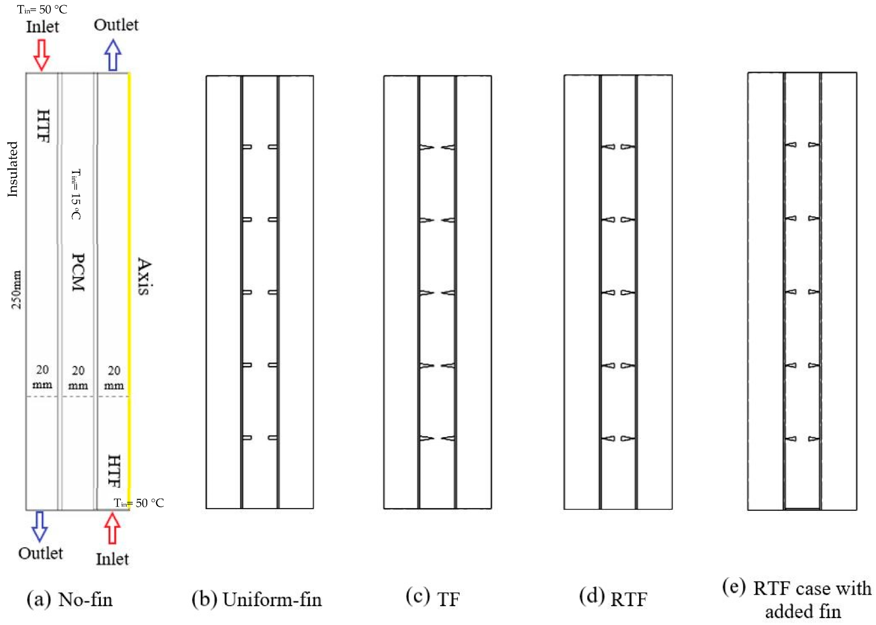
2. System Description

In this study, a vertical finned triple-tube PCM heat storage is examined considering five triangular fins connected to the interior and exterior sides of the pipe inside the middle tube. Thus, the total number of fins is considered to be ten. The triangular fins are connected in two ways, i.e., (1) the base of the triangular fin is connected to the pipe, (2) the base of the fin is located inside the PCM domain, and the pointed part of the fins is connected to the pipe. Note that the PCM is filled in the middle tube, while the heat transfer fluid (which is water) flows through the interior and exterior pipes. Furthermore, the configuration of the HTF in the inner and outer tubes is supposed to be counter-current according to the previous research in the literature [59]. In other words, the HTF flows through the outer tube in the gravity direction, while the HTF in the inner pipe is in the opposite gravity direction. The Reynolds number of the HTF flow is 2000 in both inner and outer tubes (velocity of 0.0269 m/s), which results in the flow rate of 33.8 and 169 cm3/s, respectively.
The schematics of the proposed systems, including the no-fin case, uniform-fin case, triangular finned (TF) case, reverse triangular finned (RTF) case, and the RTF case with the added fin are shown in Figure 1. It should be noted that the flow is considered axisymmetric because of the characteristics of the problem, as well as the lack of circumferential flow variations in the studied system. The triangular fins’ faces are perpendicular to the axis of the PCM tube. The boundary conditions, as well as the dimensions of the system, are shown in Figure 1a for the no-fin case. Note that the dimension for the PCM domain is selected based on various studies on triplex tube latent heat storage systems in the literature [22,57].
Different values of 2.5, 3, 3.5, and 4 mm are considered for the base of the triangular fin in comparison with the uniform-fin case, where the dimension of the fins is 2 × 5 mm, as well as the no-fin case. It should be noted that the minimum value of the base of the triangular fins is considered 2.5 mm, since, for the lower values (≤2), the height of the triangular fins is obtained higher than 10 mm, which is not possible according to the diameter of the middle tube. The height of the triangular fins is then calculated, considering the equal area for the fins in comparison with the uniform-fin case. Therefore, the PCM mass is considered similar in all the studied cases. The dimensions of the fins with the description and name of each proposed case are presented in Table 1.
In the previous paper by the authors [57], it was shown that, due to the natural convection effect in a vertical heat storage system during the phase change process, the melting process occurs in the upper region of the heat storage system faster compared to the bottom section of the heat storage unit. Thus, it was recommended to add a rectangular fin to the bottom of the heat exchanger to increase the heat transfer rate. Thus, in this paper, for the best case, a fin is added at the bottom, and its thermal performance is compared with that of the uniform-fin case with added fin, as shown in Table 1. The dimensions of the added fin are 1 × 20 mm, which is considered similar to all the added fin cases. For the best case with the added fin, two configurations are evaluated, i.e., (1) the base of the triangular fins is kept constant, and the height is then calculated; (2) the height of the triangular fins is kept constant, and the base is then calculated.
Paraffin RT-35 is used in the present study. The melting temperature of this PCM is suitable for HVAC applications in buildings. The properties of RT-35 are presented in Table 2.

3. Mathematical Modeling

To simulate the phase change phenomenon in the PCM domain, the enthalpy-porosity approach is selected to be used in this study. Density variations of the PCM result in the natural convection effect in the domain, which was determined using the Boussinesq approximation. The fluid flow was assumed to be Newtonian, transient, and incompressible. Furthermore, the flow regime was laminar. The effects of viscous dissipation are neglected in the study, while the boundary condition at the walls is assumed to be a no-slip boundary condition. The boundary condition at the outer walls of the heat exchanger is adiabatic, while high-quality insulation is considered for the walls of the PCM domain at the top and bottom of the heat exchanger. The following assumptions are considered in this study as follows [48]:
  • Consider incompressible and Newtonian fluid molten PCM.
  • Consider ignorable viscous dissipation.
  • Consider variable density while the other physical properties of PCM are constant.
  • Apply Boussinesq approximation for density variation in the liquid PCM.
Based on the assumption made, the governing equations of continuity, momentum, and energy can be developed as follows [60]:
ρ t + · ρ V = 0
ρ V t + ρ ( V · ) V = P + μ ( 2 V ) ρ β ( T T r e f ) g S
ρ C p T t + ( ρ C p V T ) = ( k T ) S L
It should be noted that the term ( S ) in Equation (2) is defined to consider the effect of phase transition interpreted as the velocity damping of the Darcy law [61] as follows:
S = A m ( 1 λ ) 2 λ 3 + 0.001 V
It should be mentioned that the value of Am called the mushy zone was assumed to be 105, based on the previous studies available in the literature [38,39]. In order to analyze the phase change phenomenon accurately, the PCM liquid fraction (λ) is defined as follows [40]:
λ = Δ H L f = { 0                                                                                                         i f     T < T S 1                                                                                                       i f     T > T L T T S T L T S                                                       i f       T S < T < T L }
In order to estimate the value of ( S L ) in Equation (3), Equation (6) is defined as follows:
S L = ρ λ L f t + ρ ( V λ L f )
Regarding the melting process, Equation (7) can be applied to estimate the rate of energy stored:
E ˙ t = E e n d E i n i t m
where E i n i   and E e n d   stand for the total energy amounts of the PCM at the initial and final times of the phase-transition course, respectively, which are the summation of sensible heat (MCpdT), and latent heat (MLf) of the PCM. t m is the melting time.

4. Numerical Analysis

To evaluate the thermofluidic characteristics of PCM during the melting phenomenon, the SIMPLE methodology is used combined with a Green–Gauss cell-based meshing technique in the ANSYS-FLUENT environment. The QUICK differencing technique is applied to solve the momentum and energy equations, while the pressure corrected equations are used numerically using the PRESTO technique. After achieving a universal pre-selection, the under-relaxation values for liquid fraction, velocity components, energy equation, and pressure correction equation are assumed to be 0.5, 0.3, 1.0, and 0.3, respectively. To stop the iterative solutions of the governing equations at each time step, the convergence criteria for the continuity, momentum, and energy equations are assumed to be 10−4, 10−4, and 10−6, respectively.

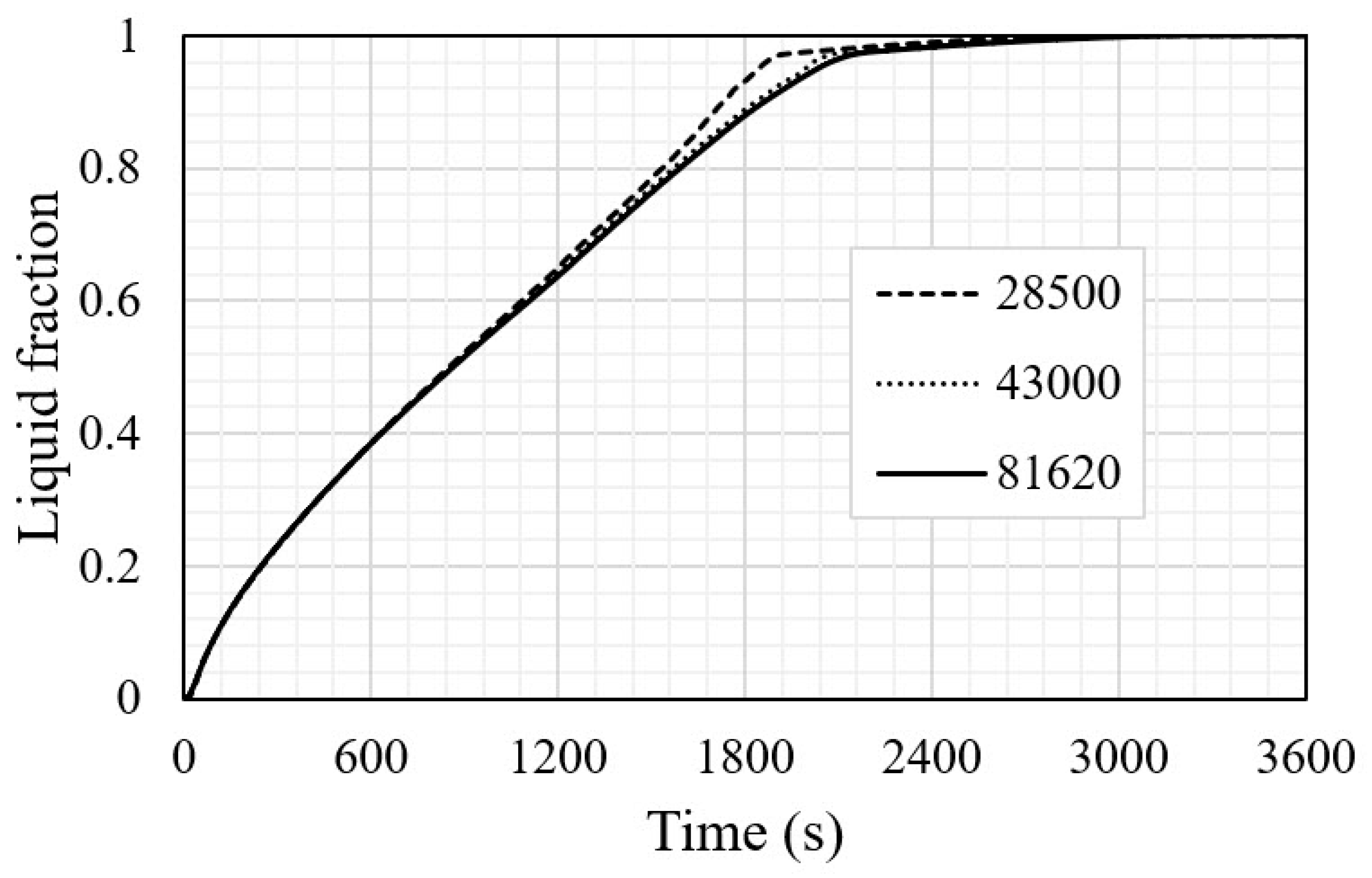
4.1. Spatial and Temporal Discretization

To apply the grid and time step size independency examinations performed for the uniform-fin case, the corresponding tests are accomplished applying the time step size of 0.2 with different cell numbers of 28,500, 43,000, and 81,620. For various cell numbers, variations of liquid fraction versus time are illustrated in Figure 2. As can be seen, values of liquid fraction for the grid sizes of 43,000 and 81,620 are almost equal (the maximum difference at the identical time is less than 0.2%). Therefore, the grid size value is set to 43,000 for further analysis. To analyze the impacts of the time step size on the melting time, the melting time amounts for different time step sizes are calculated and shown in Table 3. According to Table 3, the melting times for various time step size values are almost identical. The difference between the time step sizes of 0.1 s and 0.2 s is around 0.13%. Thus, the value of the time step size is considered 0.2 s for the next studies.

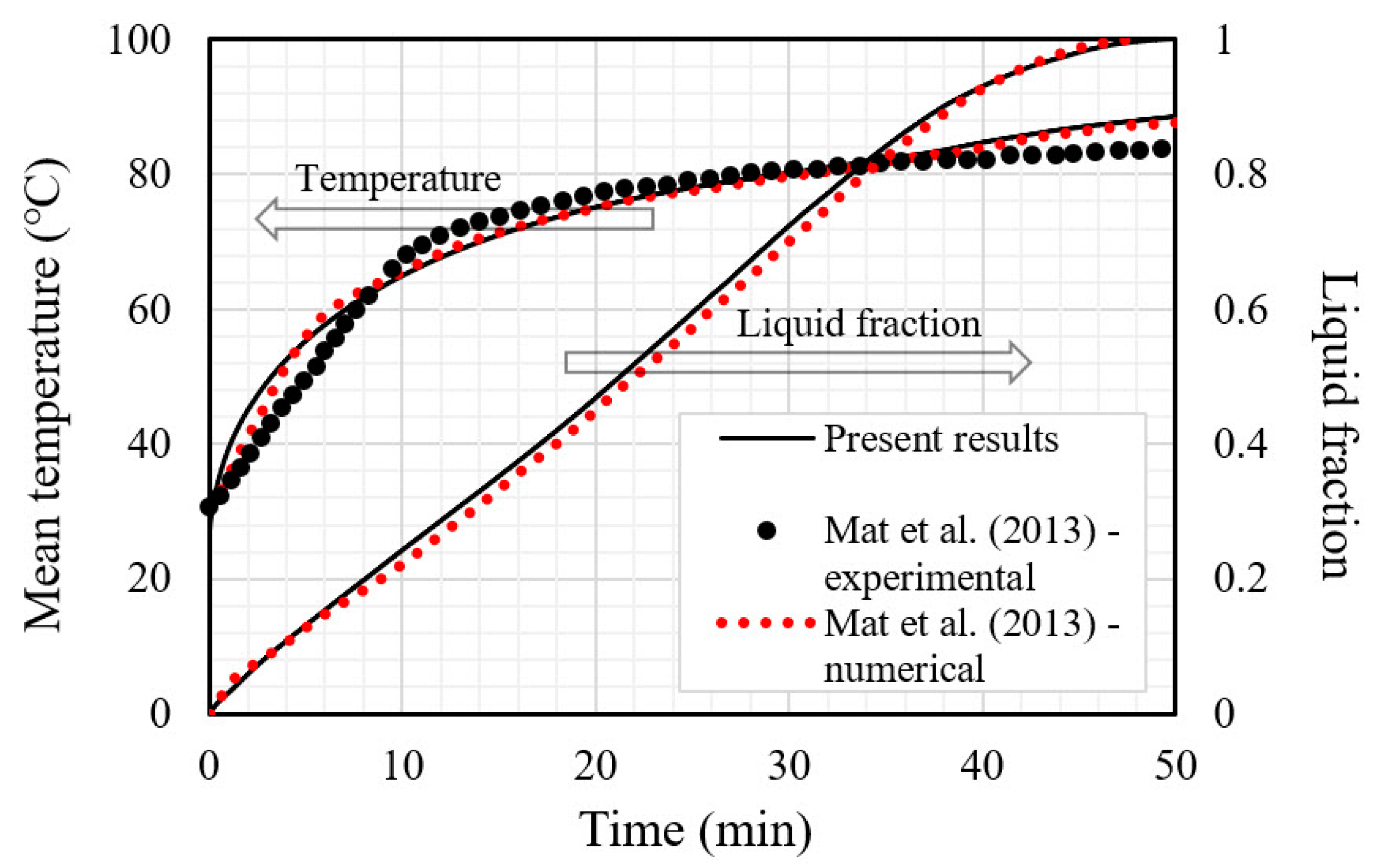
4.2. Model Validation

To verify the accuracy of the numerical scheme applied in the present study, the numerical results of the present research are validated against those of Mat et al. [62]. The same boundary conditions and performance parameters of the reference system are applied in the present model. Mat et al. [62] conducted a set of numerical and experimental investigations to explore the melting performance of a PCM (RT58) in a finned double-tube TES system. The objective of their research was to evaluate the impacts of adding staggered fins to the exterior and interior walls of the PCM shell. The data for the average PCM temperature and liquid fraction from the present study are compared to the numerical and experimental findings reported by Mat et al. [62] as shown in Figure 3. The statistical validation gave a maximum percentage error of 1.4%. Thus, the present model can be adopted for exploring the thermal characteristics of the PCM-based triple-tube system in the presence of triangular fins. It should be noted that the experimental uncertainty in the study of Mat et al. [62] is ±0.15 °C (around 0.2%) for the temperature measurement.

5. Results and Discussion

In this section, the effects of different orientations and dimensions of the triangular fins on the charging process are discussed. Then, the performance of the determined optimized system is compared with those of the uniform-fin and the no-fin cases. The final analysis investigates the effects of adding a flat fin to the bottom of the heat exchanger on the melting rate, temperature distribution, and heat storage rate. It should be mentioned that the major objective of this work is to detect the capability of the triangular fins to provide better storage operation in the thermal unit. Besides, as stated in the introduction, numerous works on double and triple-tube PCM-based heat storage units in the presence of circular or longitudinal fins have been extensively examined to enhance the efficiency of heat storage units. This study offers an additional step ahead, compared with other general works in the literature to determine an efficient finned triple-tube heat storage unit in the presence of triangular fins.

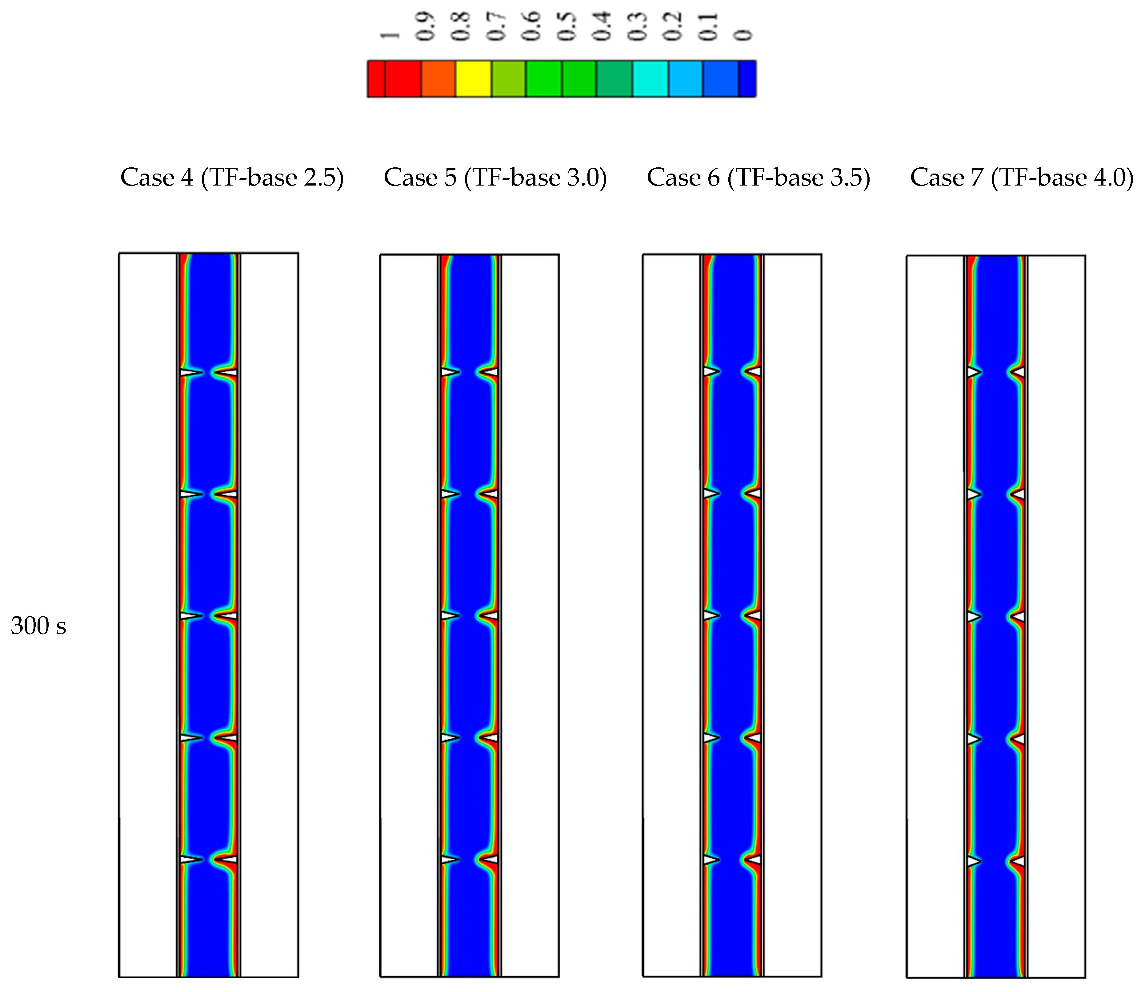
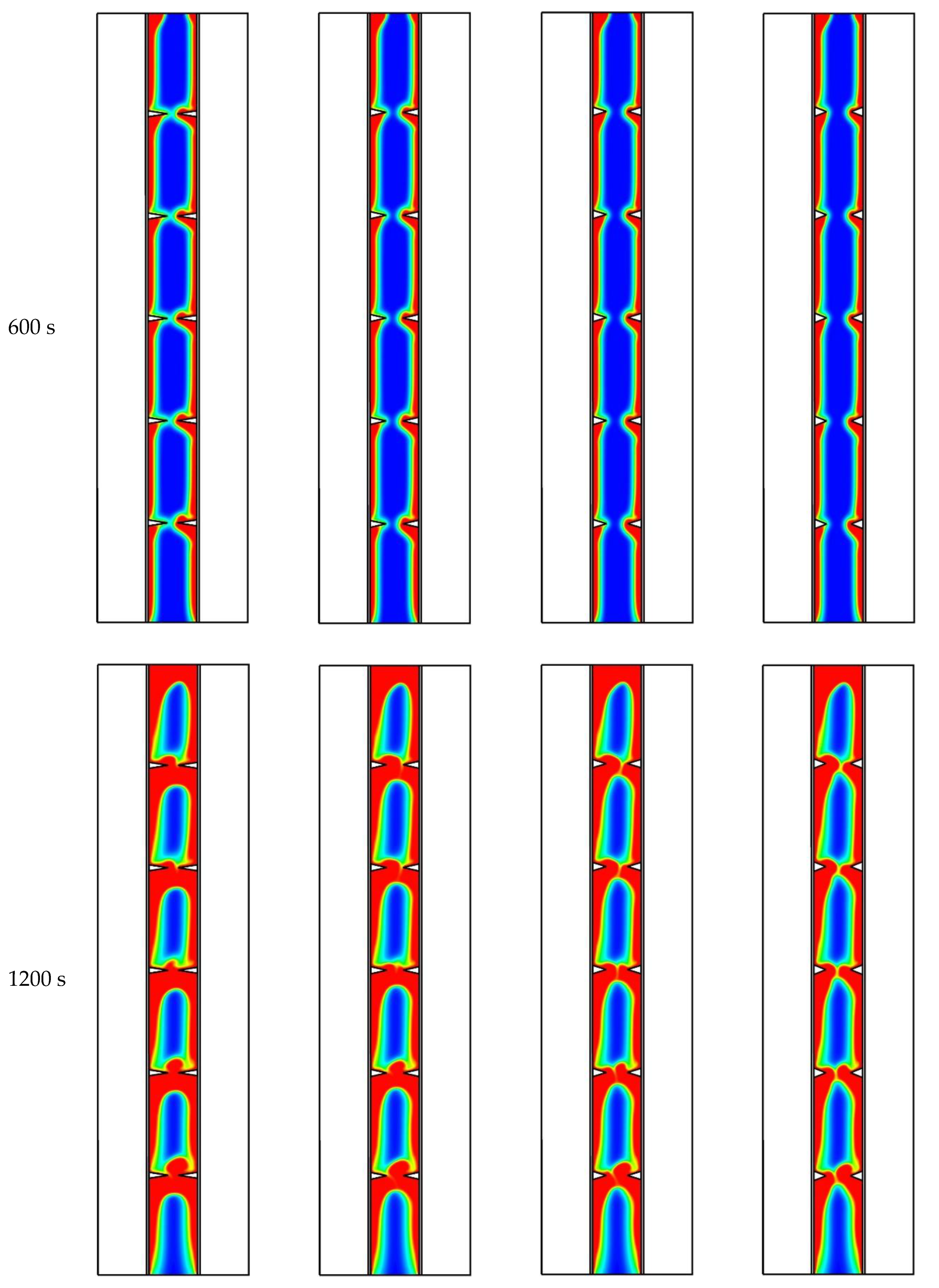
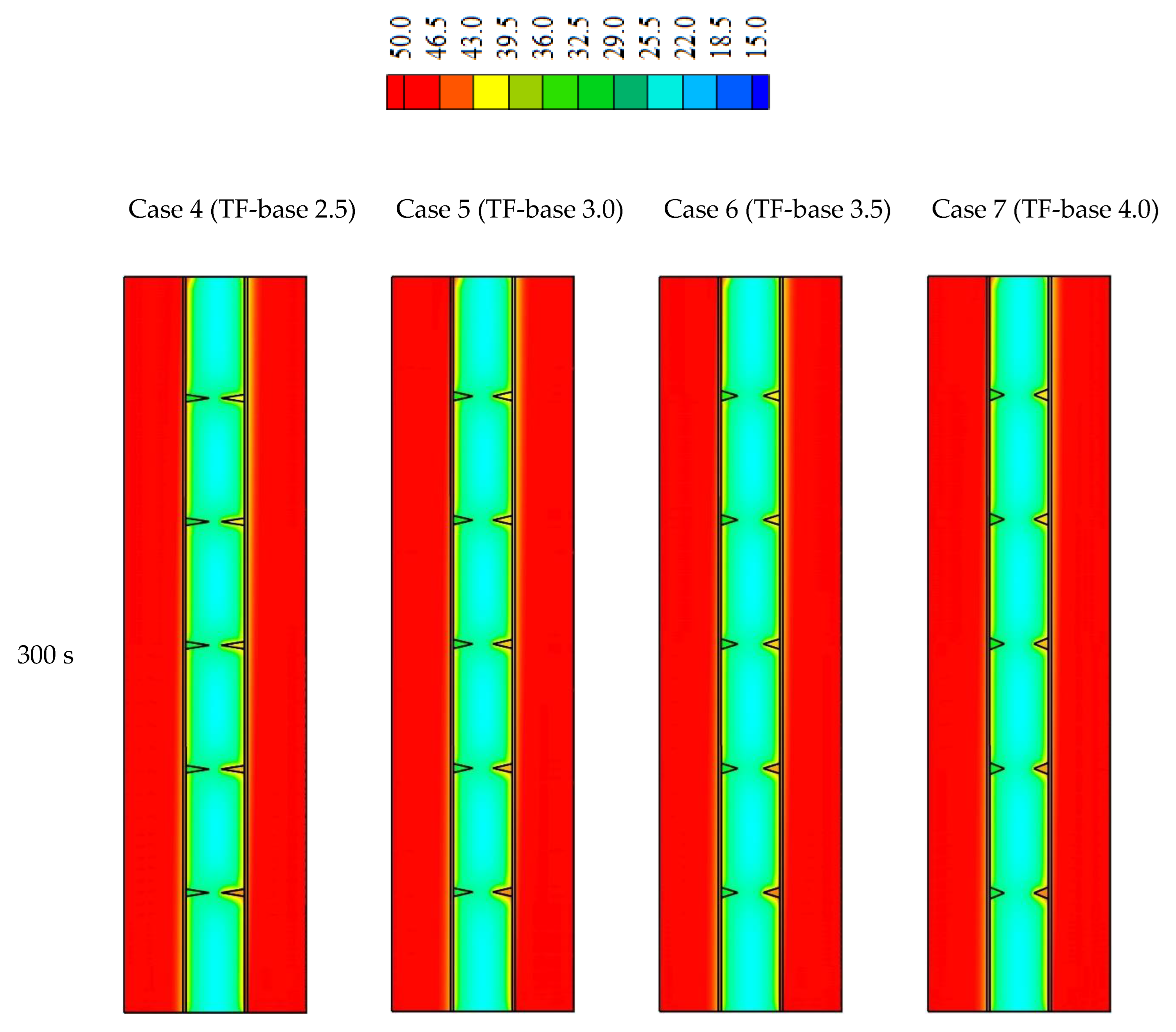
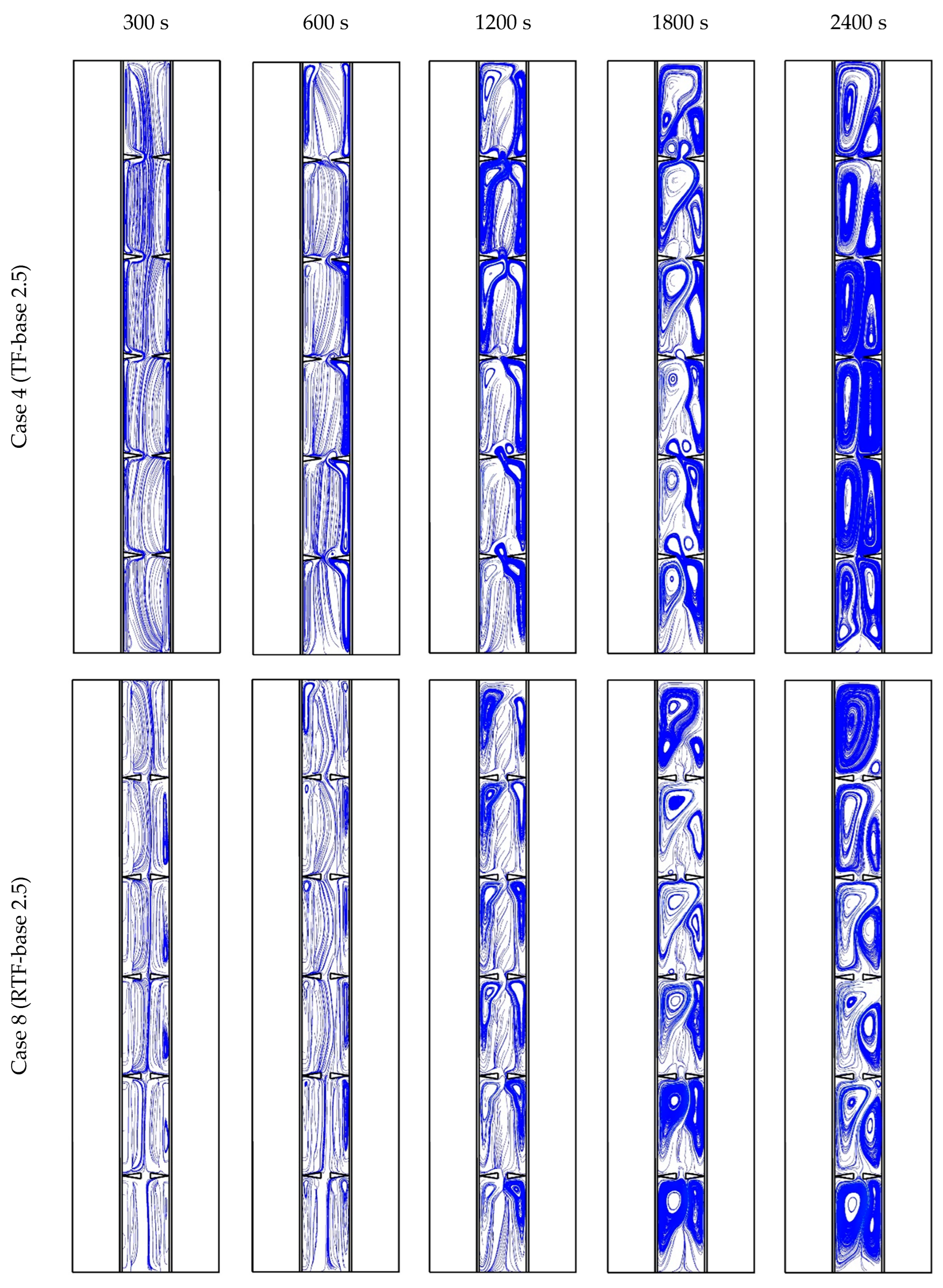
5.1. Effects of Using Triangular Fins on the Charging Phenomenon

Using fins in the heat storage unit enhances the performance of the unit due to increasing the heat transfer surface area. Increasing the average thermal conductivity of the system due to utilizing a metal fin with high conductivity also plays a major role in improving the performance. Furthermore, the fins are also capable of transferring heat to the depth of the PCM from both sides, including the inner and outer sides of the PCM domain. The fins have a dominant role in free convection behavior inside the domain as they form a barrier against the molten PCM movement. Five pairs of triangular fins are attached to the shell part of the system on the inner and the outer sides. Various cases studied in this research are shown in Table 1. The no-fin case (case 1) is considered as the reference case. The uniform-fin case with the dimensions of 2 mm × 5 mm (base × height) is considered as case 2, while case 3 stands for the uniform-fin case with an added fin to the bottom of the system. Case 4 includes five opposite triangular fins with dimensions of 2.5 mm and 8 mm (base and height) in a horizontal direction (TF-base 2.5 case). In cases 5, 6, and 7, the dimensions of the fins are changed by increasing the base value, while the fin height is reduced to keep the cross-section area of the fin constant (10 mm2 for each fin) in all the cases.
Figure 4 shows the liquid fraction development for cases 4 to 7 at various times, including 300, 600, 1200, 1800, and 2400 s. For all cases, the PCM was melted at the attached region of the wall, firstly. During the first 300 s, the adjacent PCM to the inner and outer HTF channel walls is melted. The molten area expands gradually during the melting. All the cases almost show the same behavior, and the solid part is confined between the two adjacent fins. Within 1200 s, the solid parts between the fins are separated, the solid portions remain on the opposite fins, and the area between the two opposite fins is melted. Over time, more PCM is liquefied, forming a thicker liquid layer, which is surrounded by the solid part. The molten PCM is concentrated at the top of the heat exchanger because of the natural convection effect. At the bottom of the system, the PCM is still solid. In t = 1800 s, the percentage of the PCM melted for case 4 (the case with the highest fin height (8 mm)) and case 7 (the case with the lowest fin height (5 mm)) are 87 and 83%, respectively. It can be explained that in case 4, which has the largest surface area, more heat is transferred to the PCM compared to the case with the shortest fins’ height. Because of the natural convection effect, circulation of the liquid PCM is formed in the clockwise direction. On the one hand, the triangular fins act as a barrier against this movement, which limits the free convection effect. On the other hand, the slope orientation of the triangular fins reduces this barrier and helps the molten PCM to slip on the side of the fin. The lesser the slope (case with the highest fin height), the better the barrier to keep the PCM inside the zone between the two pairs of adjacent fins. The higher slope of the fins side (the case with the shortest fin height) allows better circulation of the PCM through the zones, which helps the liquified PCM to move faster to the upper regions, and the solid PCM gathers at the bottom of the system.
Figure 5 illustrates the temperature distribution within 2400 s for cases 4 to 7. Because of the short length of the system, the HTF channels almost remain at a fixed temperature (shown in red color) during the melting process. For all the cases, the temperature increases in the adjacent region to the HTF channel walls and around the triangular fins. The temperature of the fins does not reach the thermal equilibrium, as the fins receive heat from the base side of the triangular fin and releases heat to the PCM from the other side. Therefore, the fins temperature records higher and lower values compared to the PCM and HTF, respectively. The closest area to the center of the PCM domain has the lowest temperature as this area is far from the wall and the natural convection effect is not strong enough in this area. The temperature increases gradually within 2400 s and the average temperatures reach 45.3, 45.9, 47.4, and 46.5 °C, for cases 4, 5, 6, and 7, respectively. Due to remaining the solid PCM at the bottom of the system, the bottom temperature of the heat exchanger is the lowest compared with that of the rest of the system. It should be noted that all the cases have almost the same behavior and almost the same average temperature.
Figure 6a shows the development of the liquid fraction for cases 4 to 7 during the entire melting process. The charging process occurs faster during the first 300 s due to the conduction heat transfer with the solid PCM, and then the melting process is reduced slightly due to the increasing heat transfer rate by convection compared with that of conduction. Between t = 2100 and 2200 s, the curves become a plateau and more than 96% of the PCM of all the cases is melted. Case 4 has the fastest phase change process due to having the largest surface area of the fin, while case 7 has the slowest phase change phenomenon. The average temperature noticeably increases during the first 200 s because of the conduction heat transfer based on Figure 6b. Additionally, the average temperature of case 4 TF base 2.5 is the highest due to having the largest surface area. The temperature of the PCM reaches the thermal equilibrium within 3000 s.

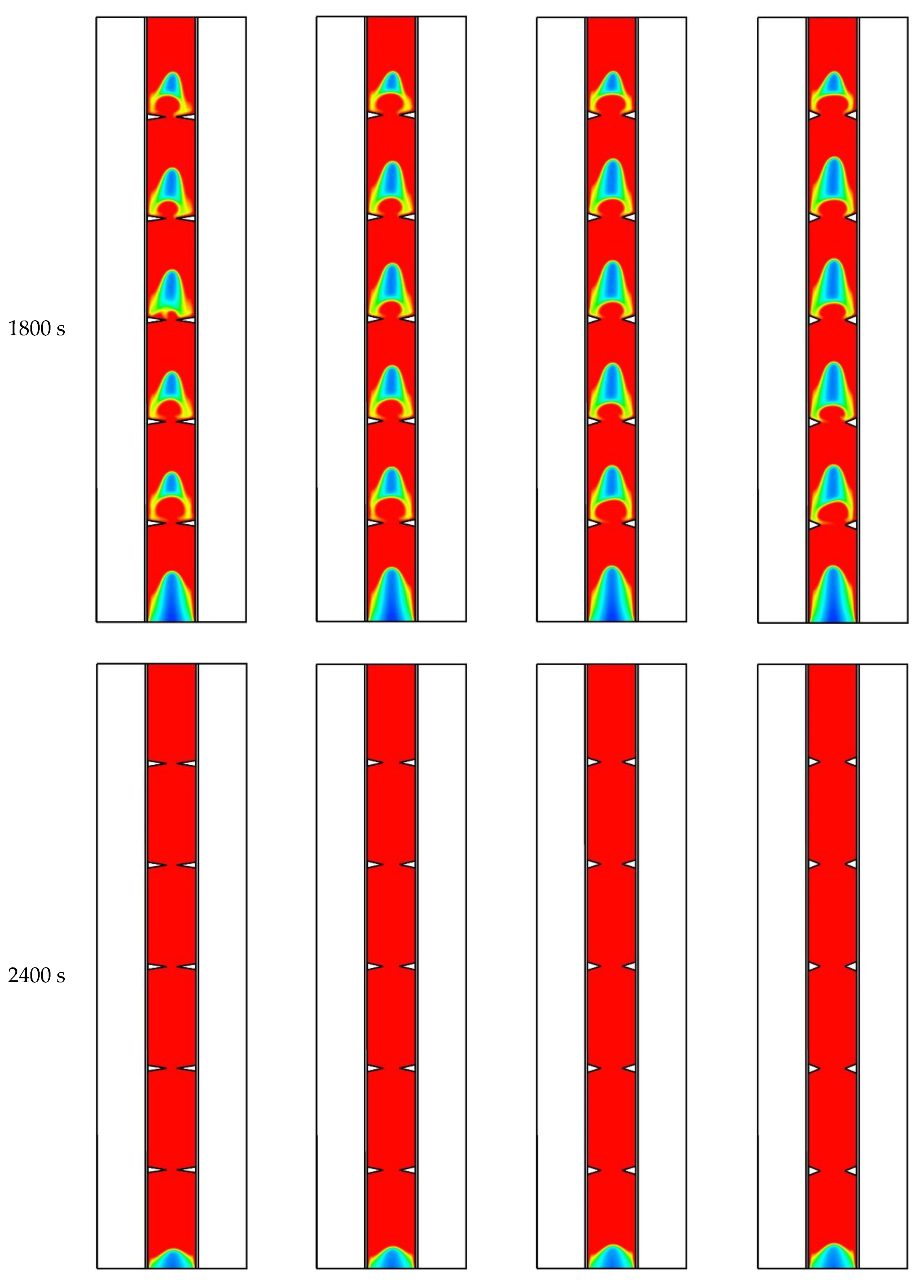
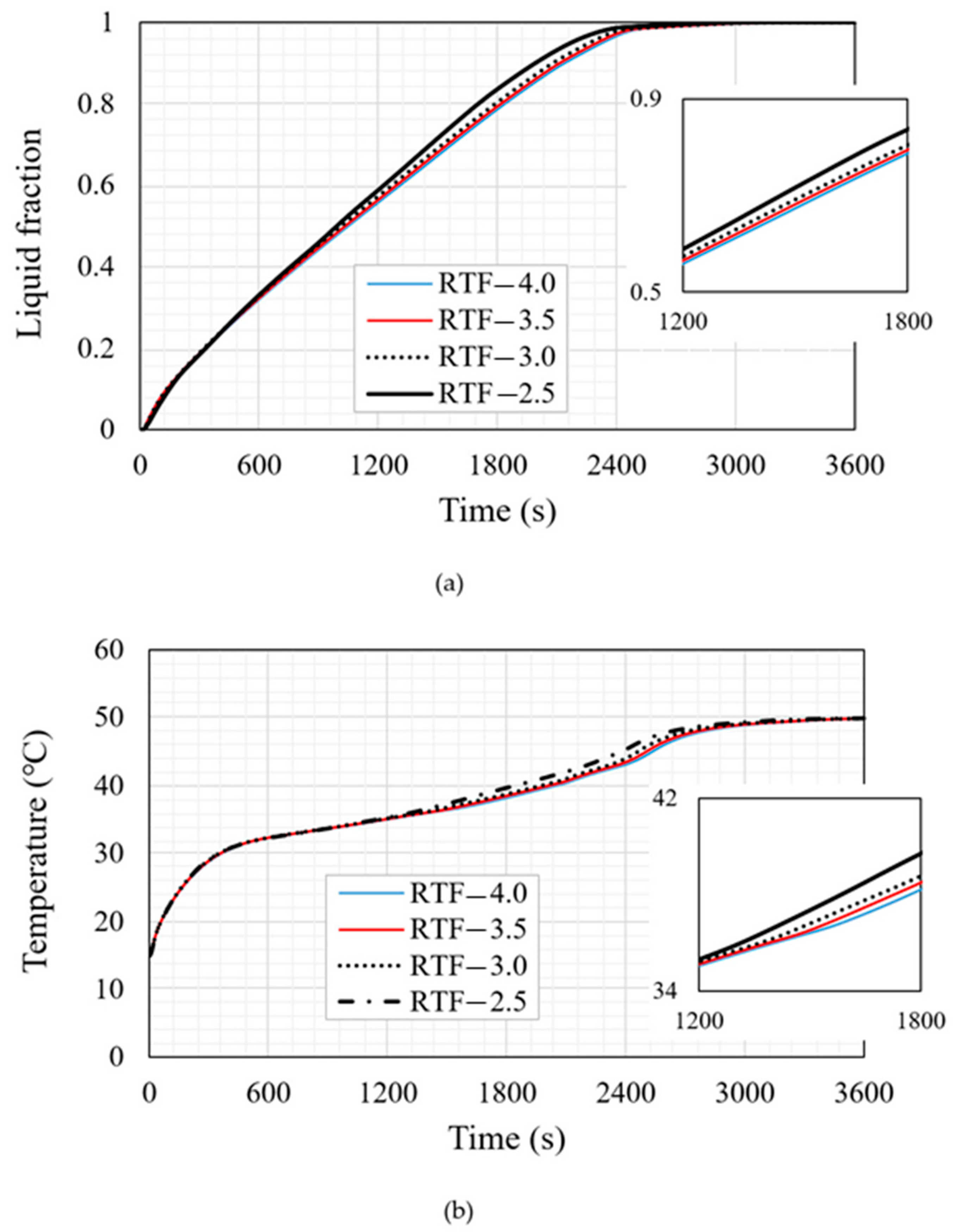
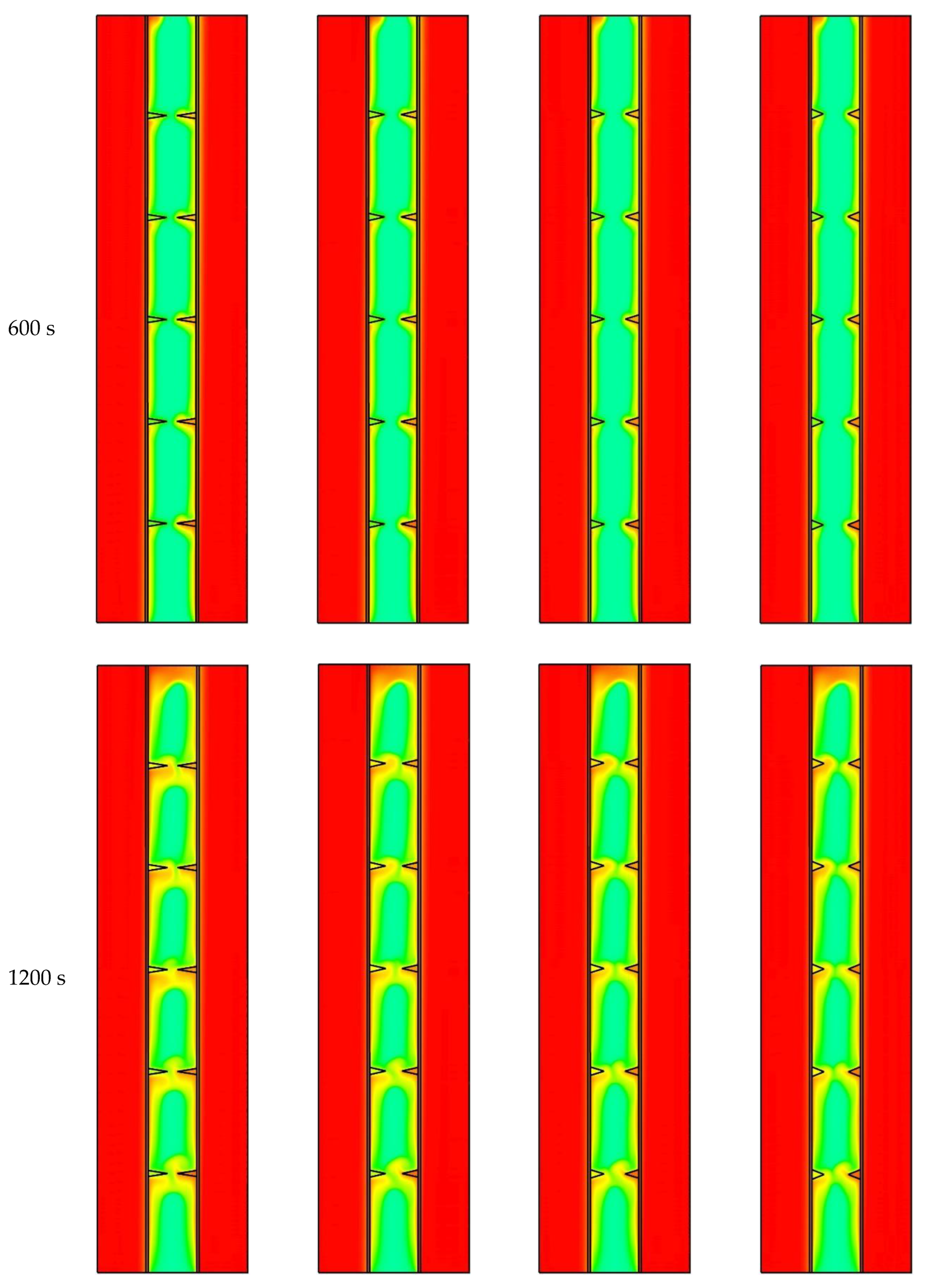
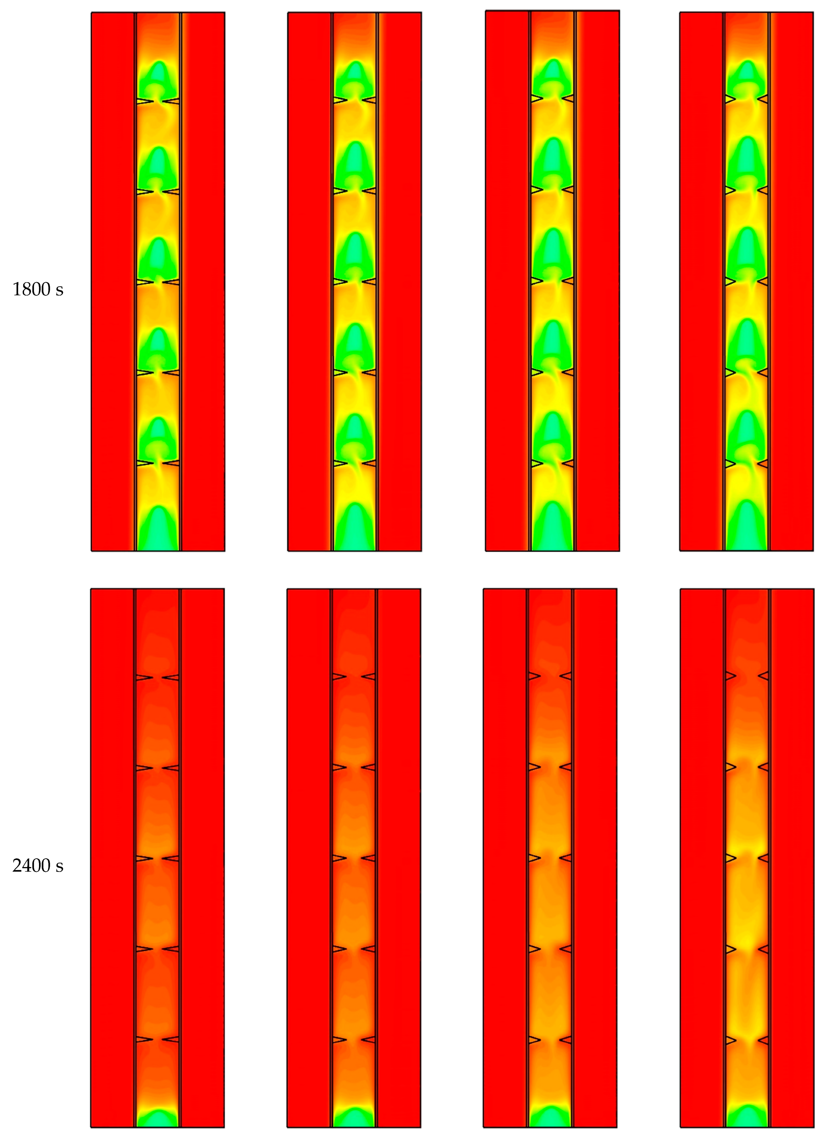
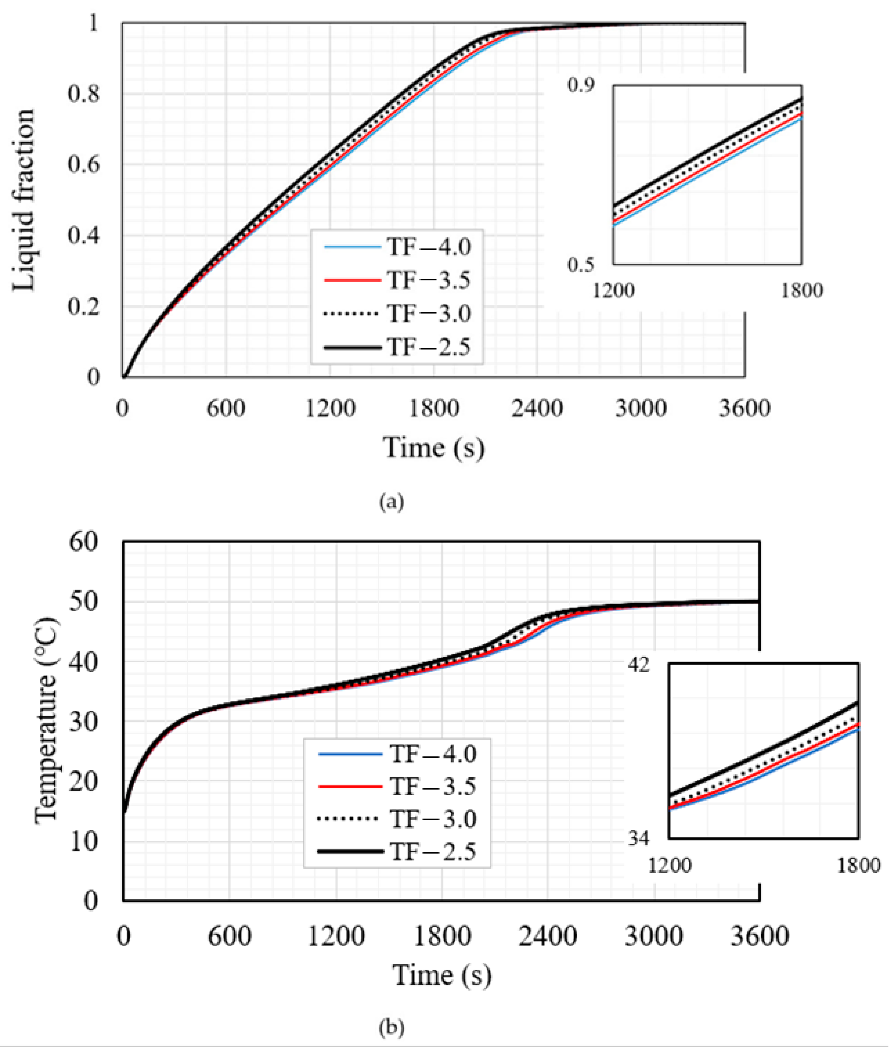
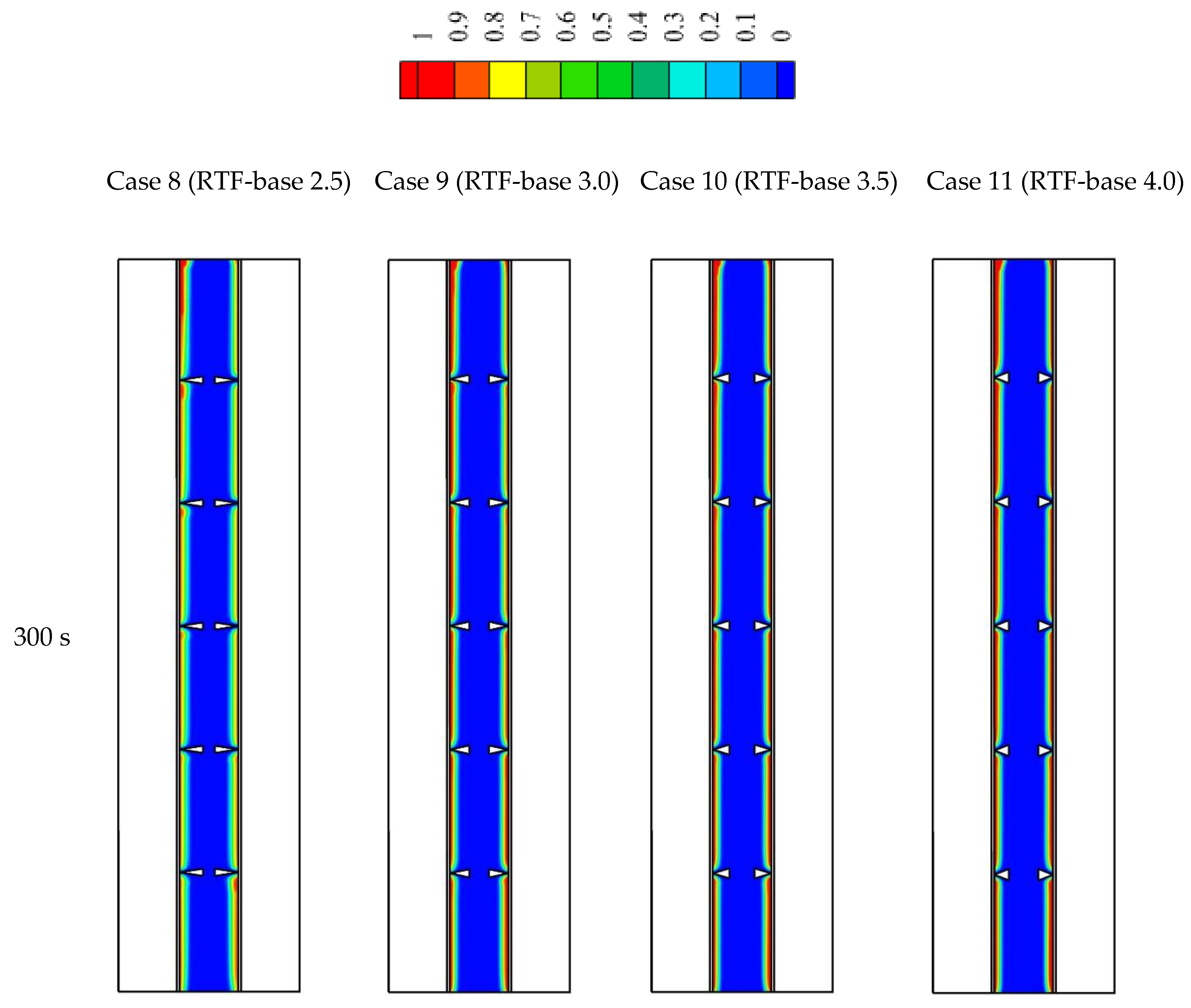
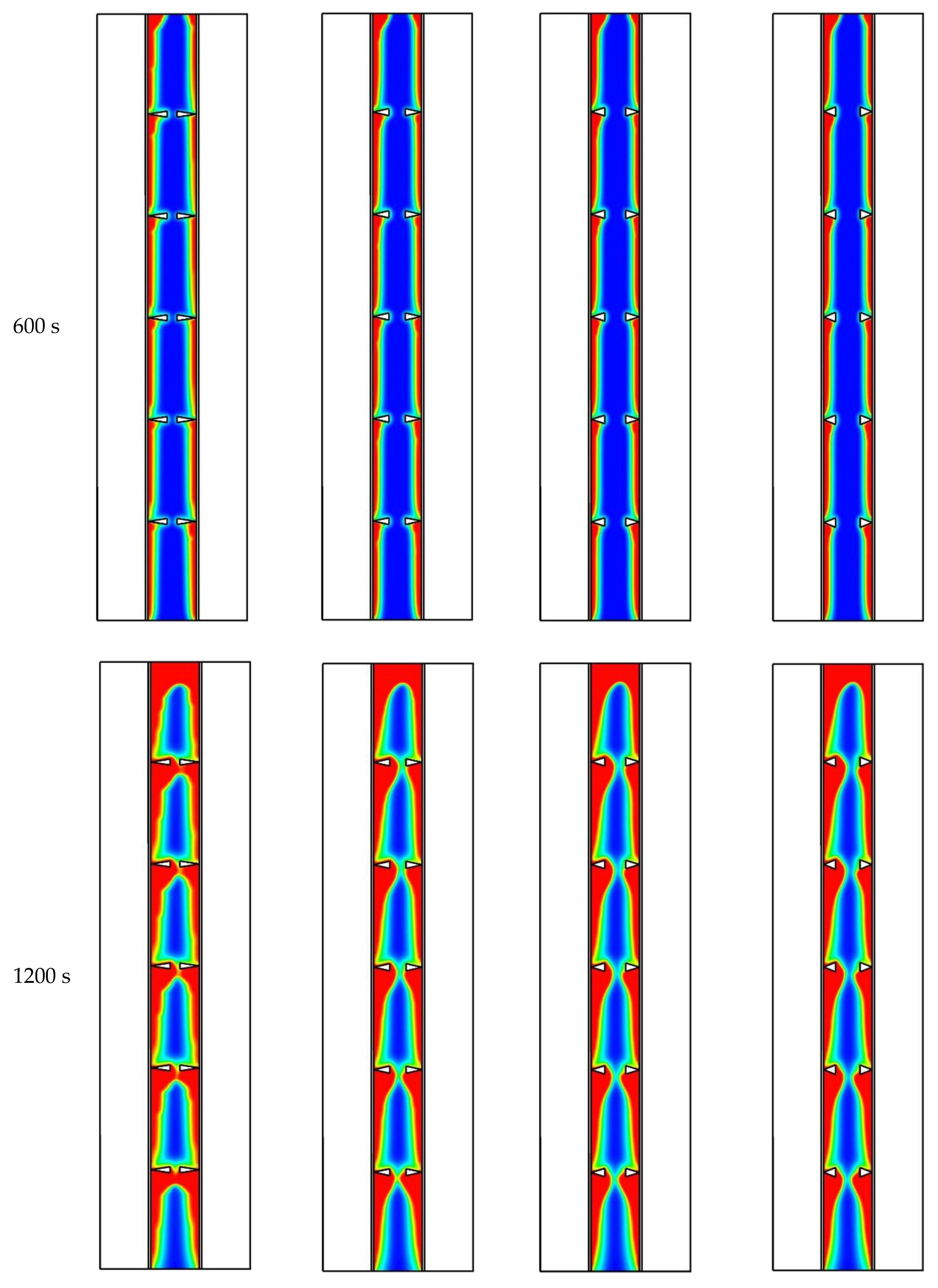
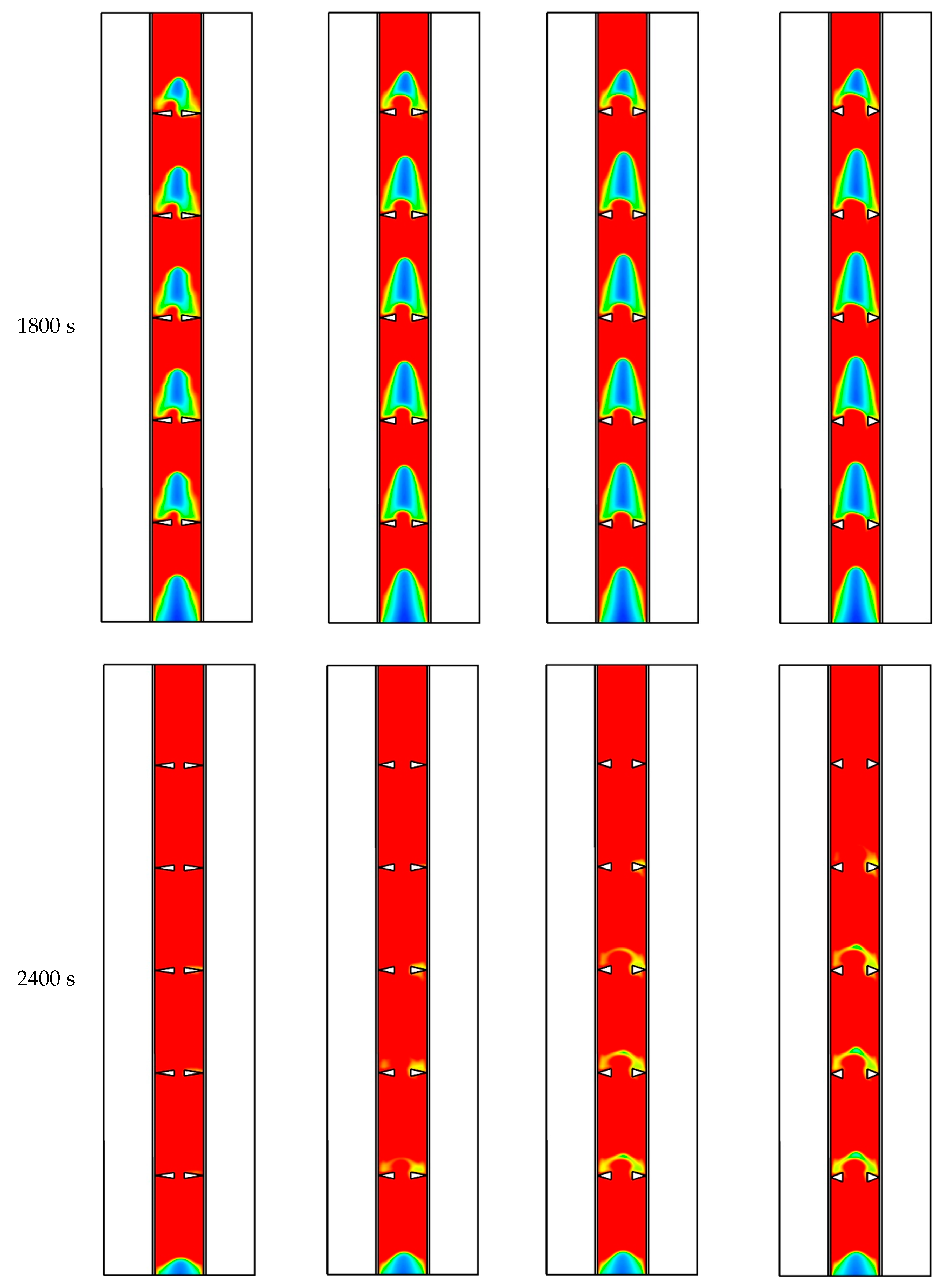
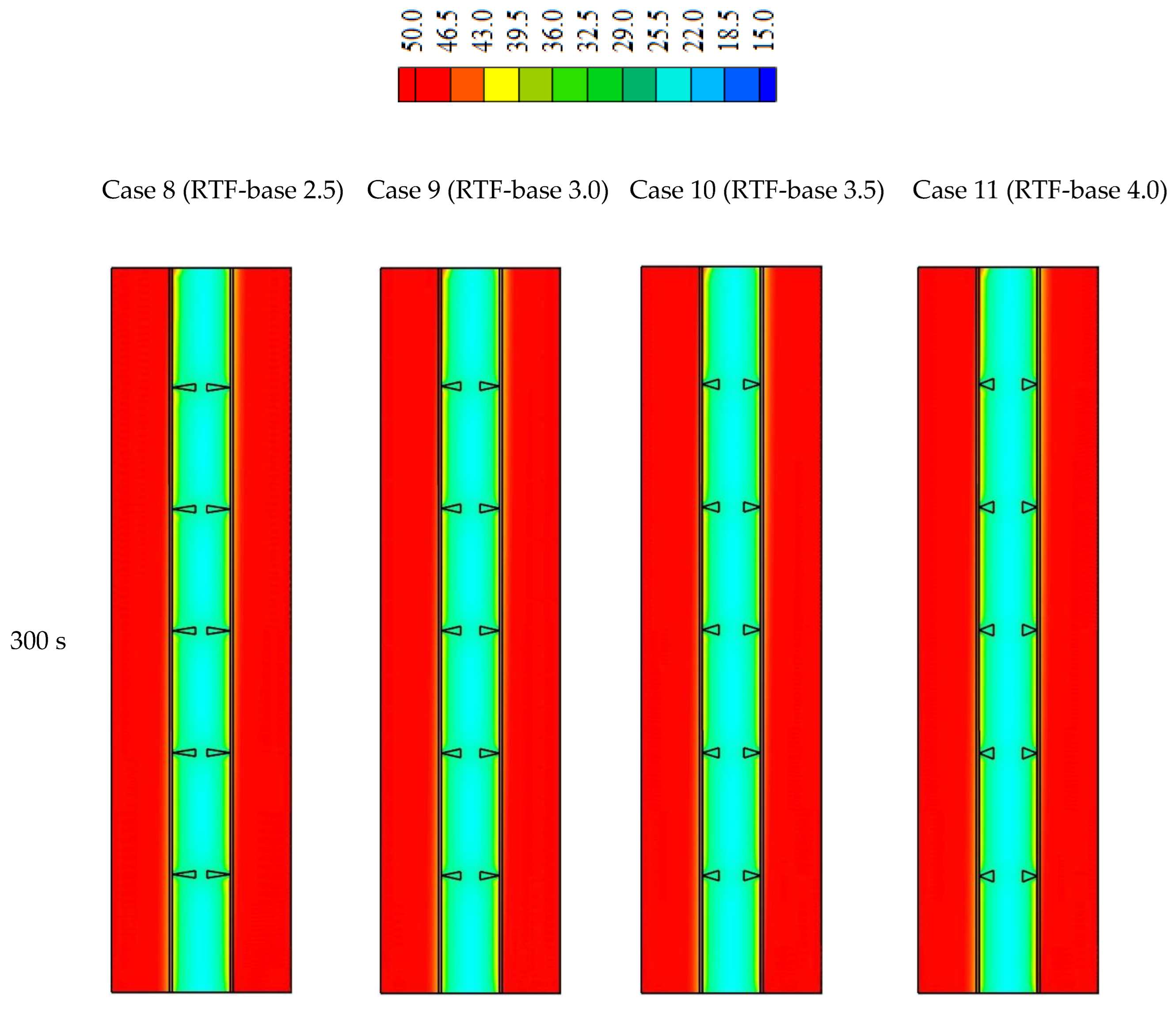
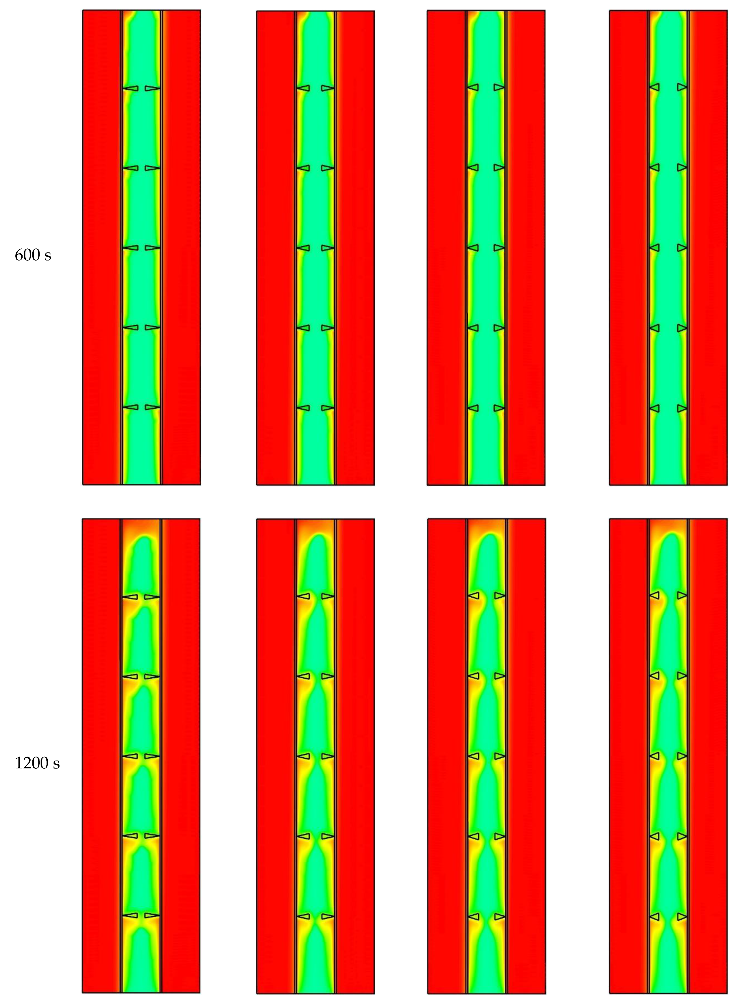
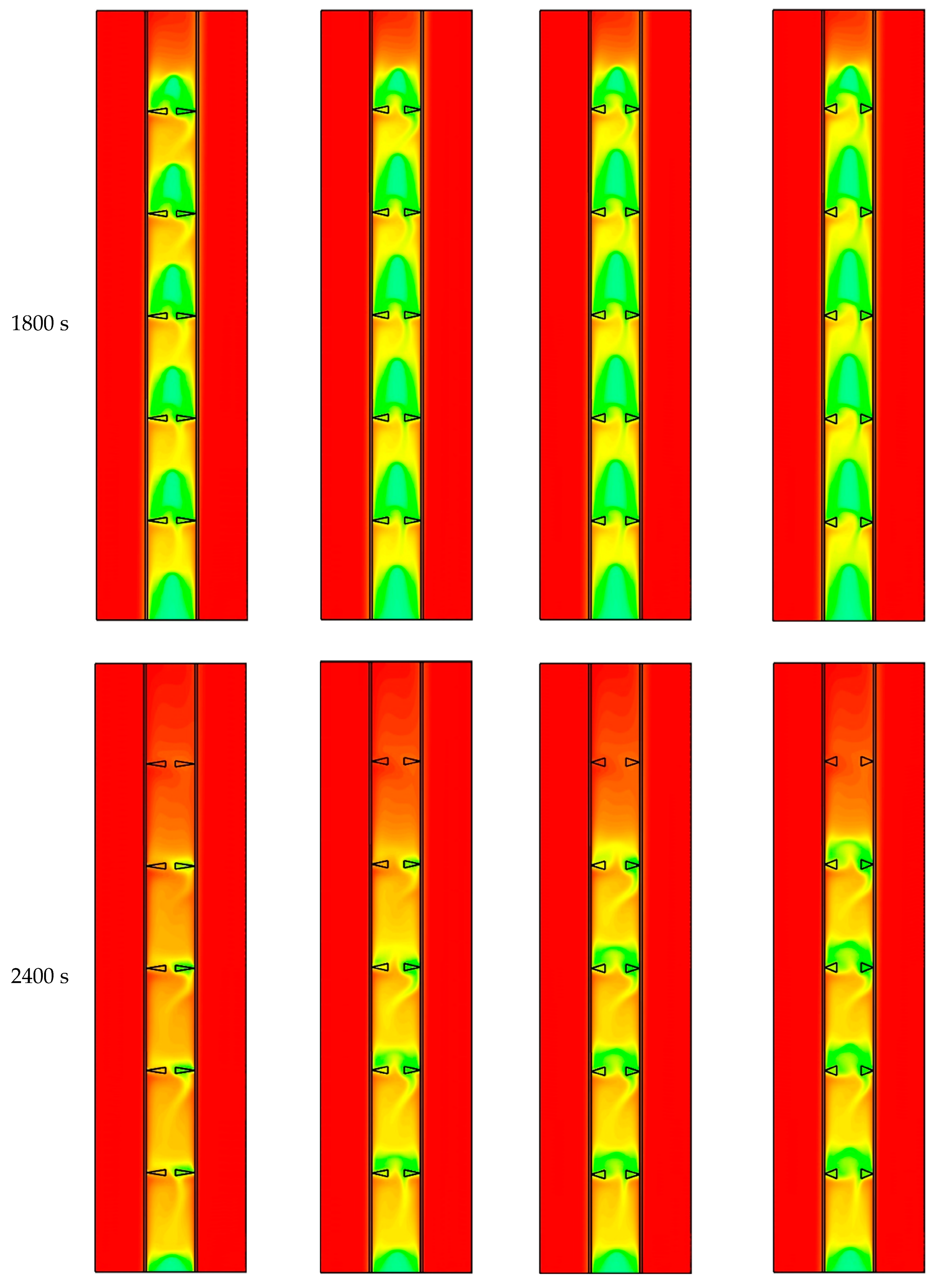
5.2. Effects of Using Reverse Triangular Fins on the Charging Process

In this part of the study, the impacts of triangular fin orientations on the charging process are investigated. In other words, the directions of the triangular fins are reversed and the tip part of the triangular fins is attached to the inner and the outer walls of the HTF channels, as shown in Figure 7. As mentioned before, the longer fins provide a higher surface area compared with the shorter fin. A larger surface area accelerates the melting process due to transferring more heat to the PCM. Although the point connection limits the amount of the heat transfer rate from the channel of the fin and then to the PCM; however, the heat is still transferred enough to the fin (the fins in Figure 7 and Figure 8 are presented in white color to be observed clearly). The fins form a strong barrier that limits the circulation of the molten PCM. This behavior helps the molten PCM to circulate inside each zone rather than the whole system. Within 600 s, the solid PCM is still connected through the zones. The solid parts finally separate at t = 1200 s and they are arranged on the pairs of opposite fins. The solid parts shrink during melting and, through time, most of the PCM is melted except for the region at the bottom part of the system. Case 8 shows a higher performance, compared with the other cases, as the entire zone (98.8%) is melted except for the region at the bottom of the unit. It should be noted that small portions of the solid part remain in different places of the domain for the other cases.
Figure 8 illustrates the temperature contours of cases 8, 9, 10, and 11. As the heat is transferred to the PCM, the PCM domain is warmed and the temperature increases gradually. The longer fins (higher surface area) transfer more heat to the PCM resulting in faster melting and higher temperature. The temperature rises at the top of the unit initially due to the convection heat transfer. Furthermore, an increase in the temperature at the top of each zone is also observed. Regarding the shortest fin, the average temperature reaches 41 °C within 2400 s, while the corresponding value of the longest fin is 46 °C.
Figure 9 shows the streamlines of cases 4 and 8 at various times. Regarding case 4, the liquid PCM rarely circulates within the zones, especially at the early stage of the melting process (300–600 s). Due to the slope direction of the fins toward the PCM domain, more movement is achieved among the zones. Because of the slope direction of the reversed fins toward the HTF channel (case 8), the liquid PCM is transferred hardly through the zones between the two pairs of the opposite fins. In other words, in the reverse triangular fins, a strong barrier is formed against transferring the molten PCM through the zone, causing all the PCM to just circulate in their own zones.
The influence of the reverse triangular fin on the melting process is investigated in Figure 10a for cases 8 to 11. Different dimensions of the fins are considered in this part. The longest fin provides a faster charging process due to having the largest surface area, resulting in transferring more heat to the PCM domain. The effect of the fins height on the melting procedure appears at a constant rate until 2400 s (the PCM liquid fraction is 99% for case 8 and 96% for case 11). Then, the melting rate reduces until the PCM is melted totally. It is worth mentioning that the area of the different fins is constant for various dimensions, which guarantees the value of the PCM utilized in various cases to be the same. Figure 10b shows the average temperature development of the PCM for the reverse triangular fins. The temperature increases rapidly due to the conduction heat transfer and then reduces. At 1800 s, the temperature of the PCM for the longest fin is 40 °C, which is higher than the PCM temperature for cases 9, 10, 11 by 3%, 5%, and 7%, respectively. Within 3000 s, the PCM for all the cases reaches almost the same temperature.

5.3. Summary of Selecting the Best Configuration

Table 4 shows that the cases with the longest fin (base 2.5 mm) are the best cases among all the studied cases, and the case with a reverse triangular fin shows higher performance. This behavior is caused by, firstly, the longer fins, which provide a larger surface area to enhance the heat transfer to the system. Secondly, the reverse triangular fin provides a strong barrier against the circulation of the liquid PCM causing the liquid PCM to circulate within the zone rather than the whole system. Case 7 is known as the worst case due to having the highest melting time and the lowest heat storage rate. The total melting time of the PCM in case 8 is 2997 s, which is shorter than those of cases 4 and 7 by 2.1% and 7.2%, respectively. The heat storage rate of case 8 (56.1 W) is the highest among all other cases, which is greater than those of cases 4 and 7 by 1.9% and 6.5%, respectively. The outline of this section shows that the longest fin offers a higher surface area of heat transfer, resulting in a faster charging process and a higher heat storage value. The reverse triangular fin provides a better barrier against the circulation of the molten PCM, which slightly accelerates the melting process and improves the thermal storage rate. Although there is a small difference between the calculated parameters in cases 4 and 8, case 8 records slightly higher performance, and, consequently, it is selected as the reference case for the next investigations.

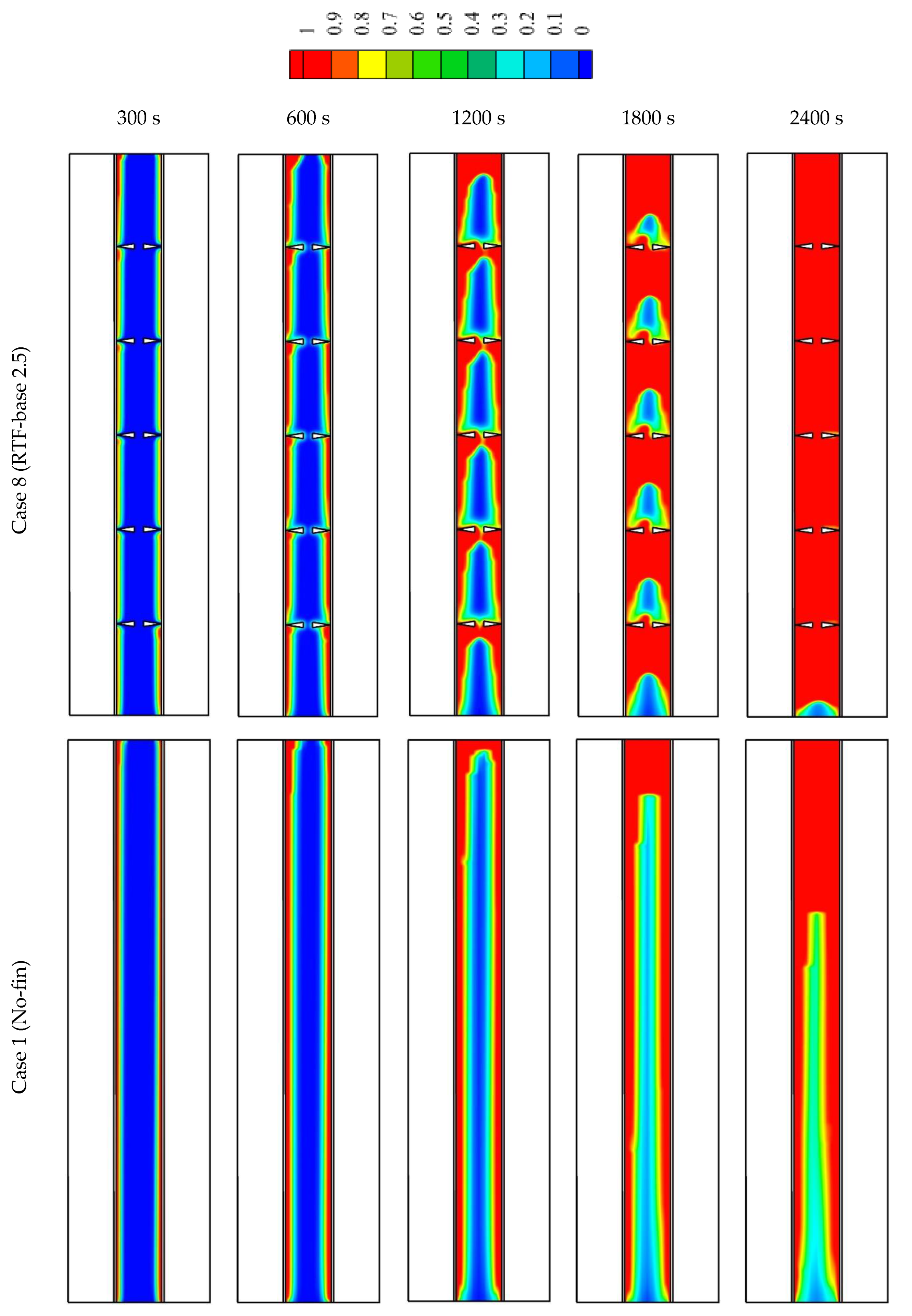
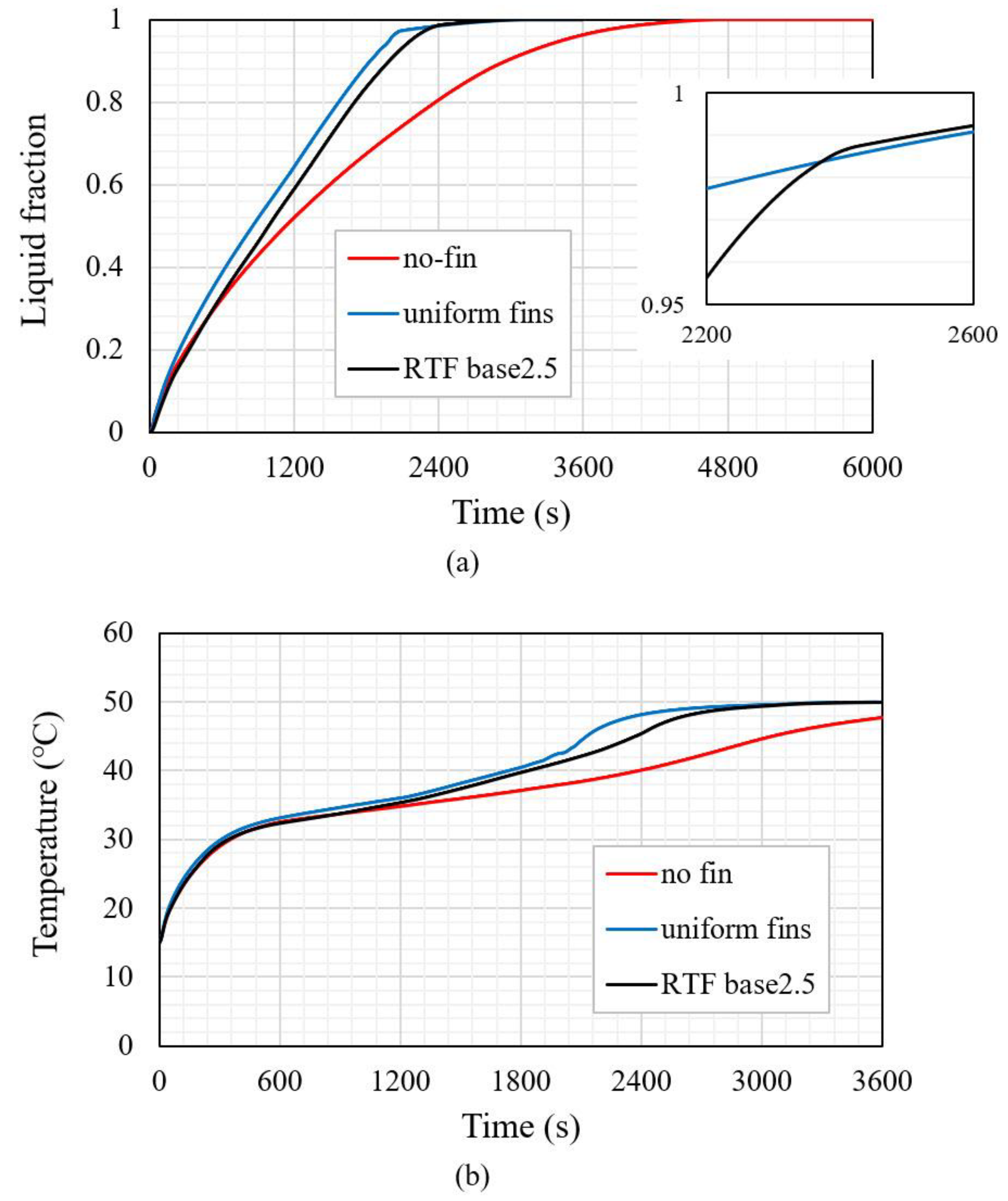
5.4. Comparing the Thermal Performance of Reverse Triangular Fins with That of No-Fin and Uniform-Fin Cases

Figure 11 compares the liquid fraction development of the reverse triangular fin (Case 8) with that of the no-fin (case 1) and uniform-fin (case 2) cases at different times. The thermal behavior of the charging process was explained previously for case 8. Regarding case 1, the melting process initially starts at the adjacent area of the HTF channel wall. The liquid phase expands during the melting process and then it accumulates at the top region of the system, while the solid part remains at the bottom due to the Boussinesq effect. Within 2400 s, just 80% of the PCM is melted. This can be attributed to the limited heat transfer mechanism provided by the channel walls due to the absence of the fins. Considering case 2, the melting process occurs faster as the fins increase the heat transfer surface area, as well as the average thermal conductivity.
Figure 12a shows the liquid fraction development of cases 1, 2, and 8. For the no-fin case, the PCM melts logarithmically and needs a relatively long time to be melted. Regarding cases 2 and 8, the melting processes have almost the same behavior. It should be mentioned that case 2 benefits from higher performance compared to case 8 from t = 0 to 2350 s, of which 98% of the PCM in both cases is melted approximately. In fact, the existence of fins causes the charging process of cases 2 and 8 to occur at a higher rate compared to the no-fin case. After t = 2350 s, the melting process of case 8 occurs faster than that of case 2, and the total PCM is melted within 3000 s as illustrated in Figure 12a. Figure 12b shows the variations in the mean temperature of the PCM for cases 1, 2, and 8. Regarding the no-fin case, the mean temperature of the PCM is the lowest, and it does not reach the thermal equilibrium even within 3600 s. For cases 2 and 8, the mean temperature shows approximately the same behavior at various times. The PCM in cases 2 and 8 reach the thermal equilibrium within 3600 s and this indicates that the shape of the fin has a tiny impact on the melting time and the mean temperature distribution. Table 5 presents the total melting time and heat storage rate for cases 1, 2, and 8. It indicates that the total melting time and heat storage rate of cases 2 and 8 are almost similar, while a considerable difference between these values and those of the no-fin case is observed. Case 8 is selected to be the best case due to having the lowest total melting time and highest heat storage rate compared with the other cases. It should be mentioned that the melting times of cases 1 and 2 increase by 55.3 and 2.0% compared with that of case 8. Furthermore, the heat storage rates of cases 1 and 2 reduce by 35.4 and 1.7% compared with that of case 8.

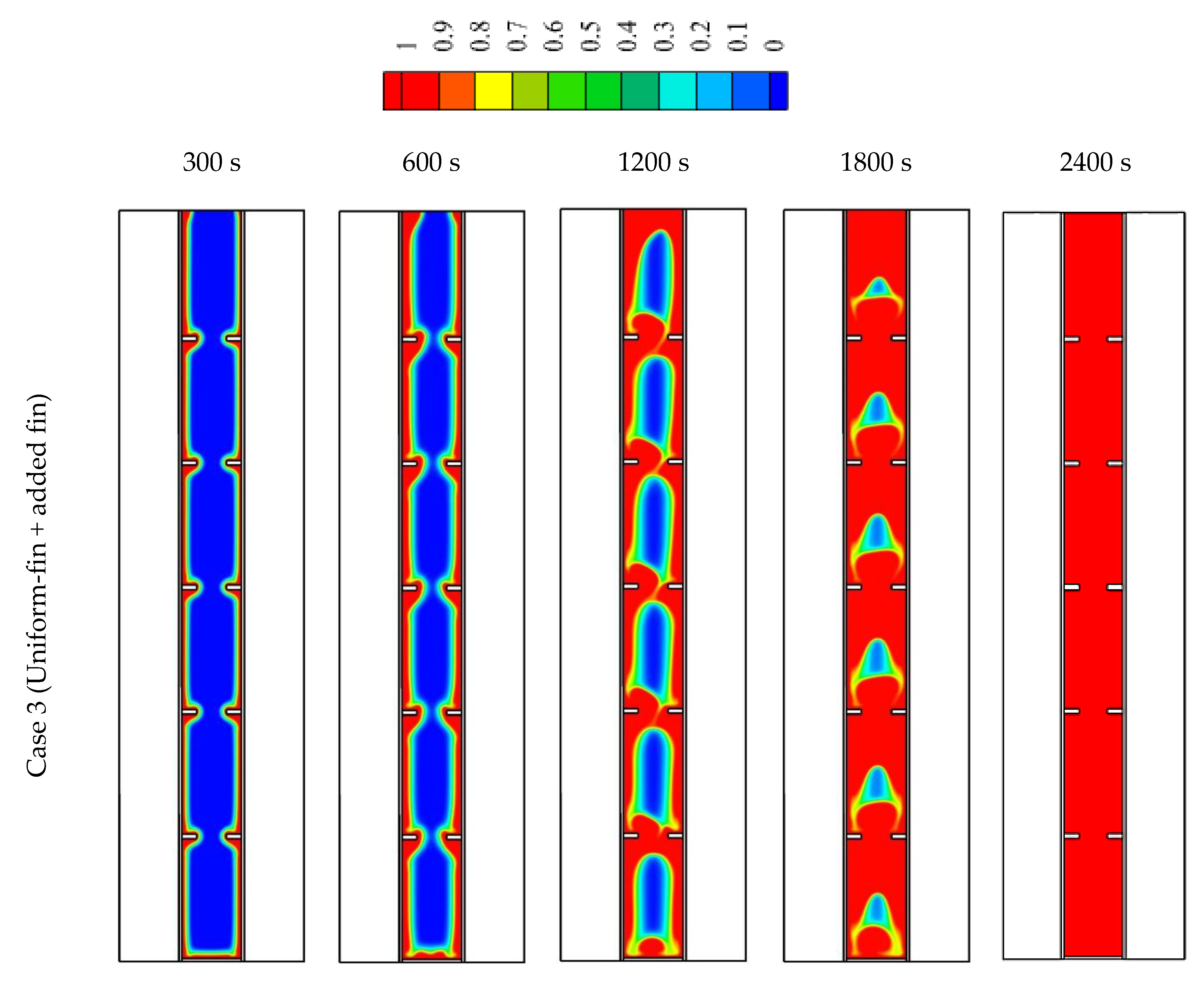
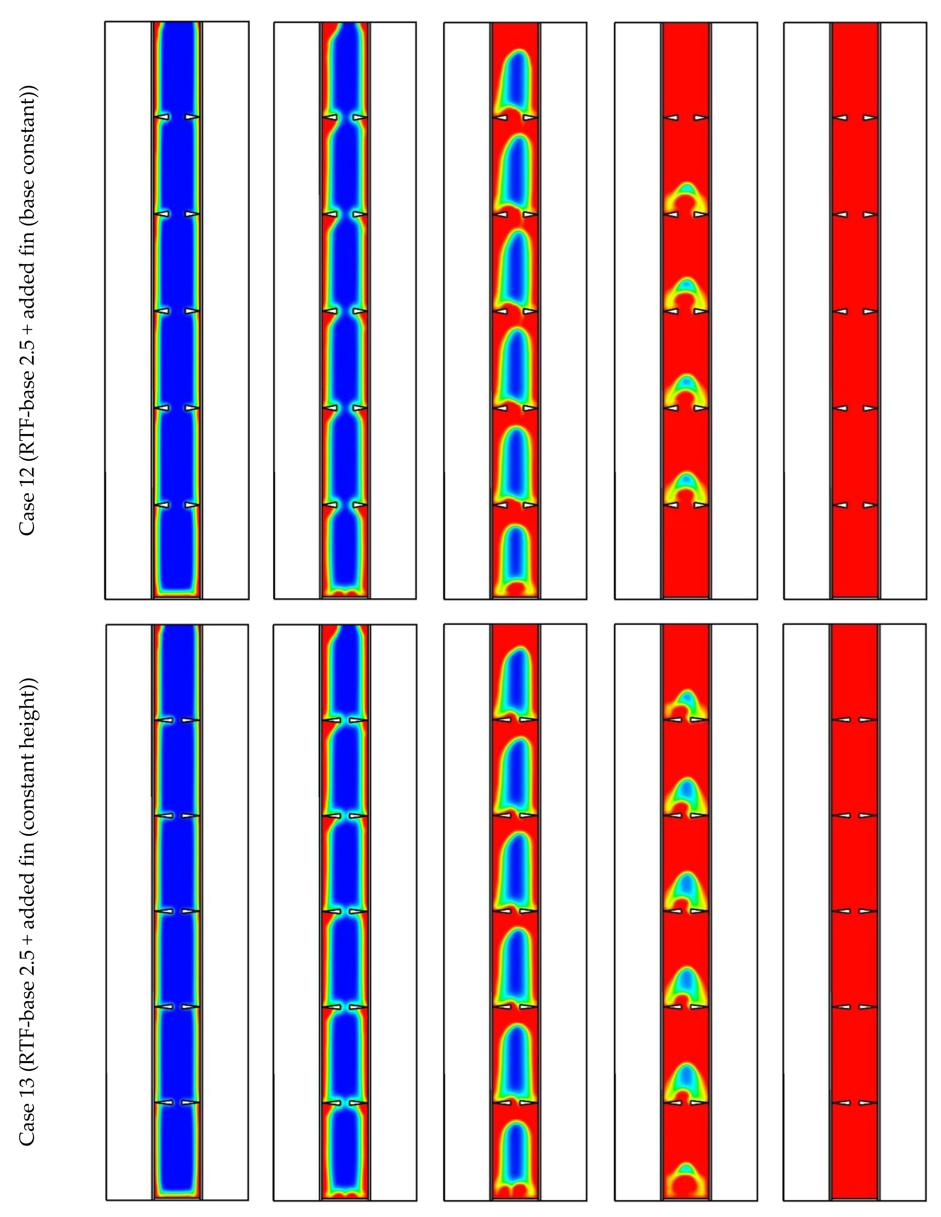
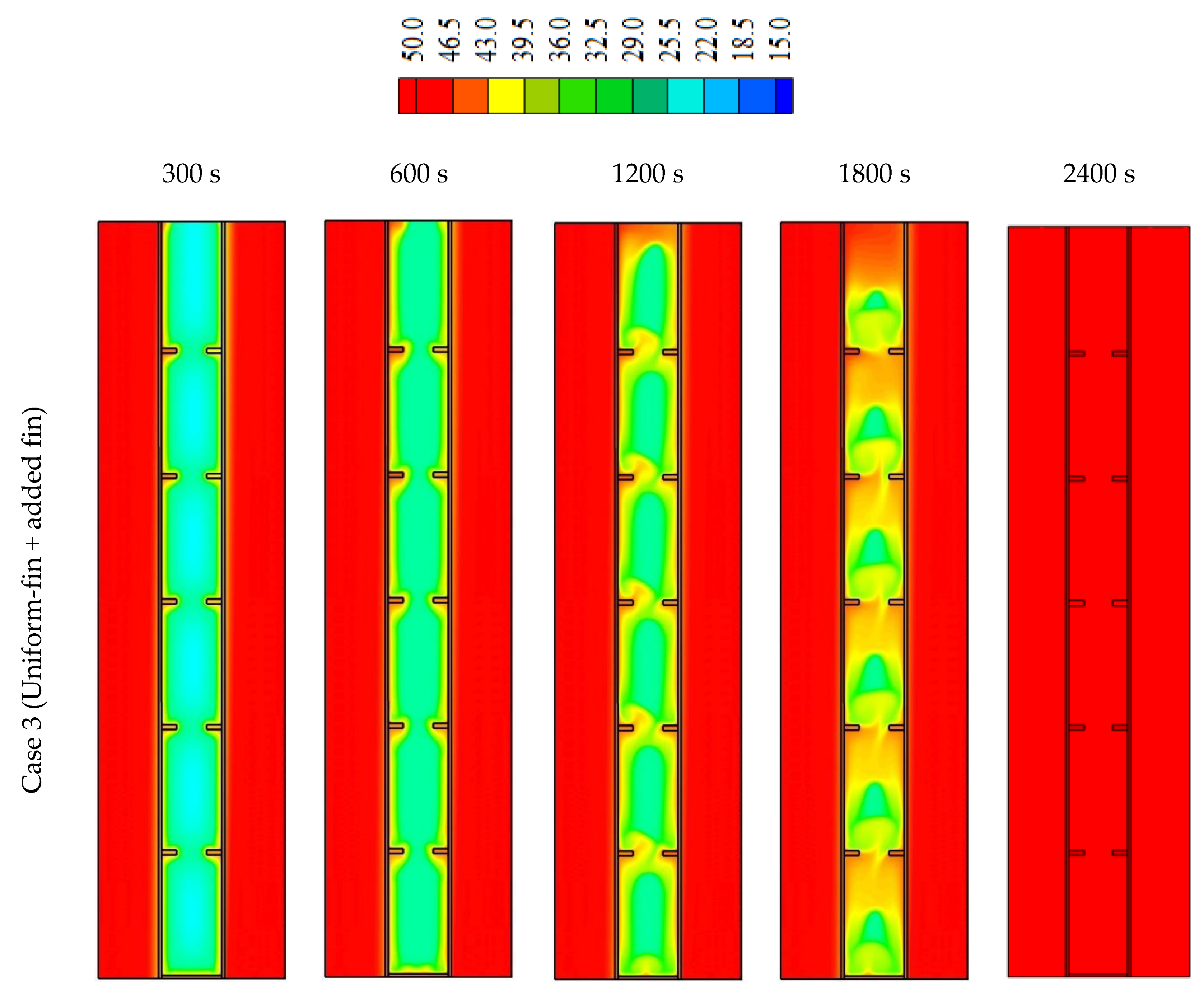
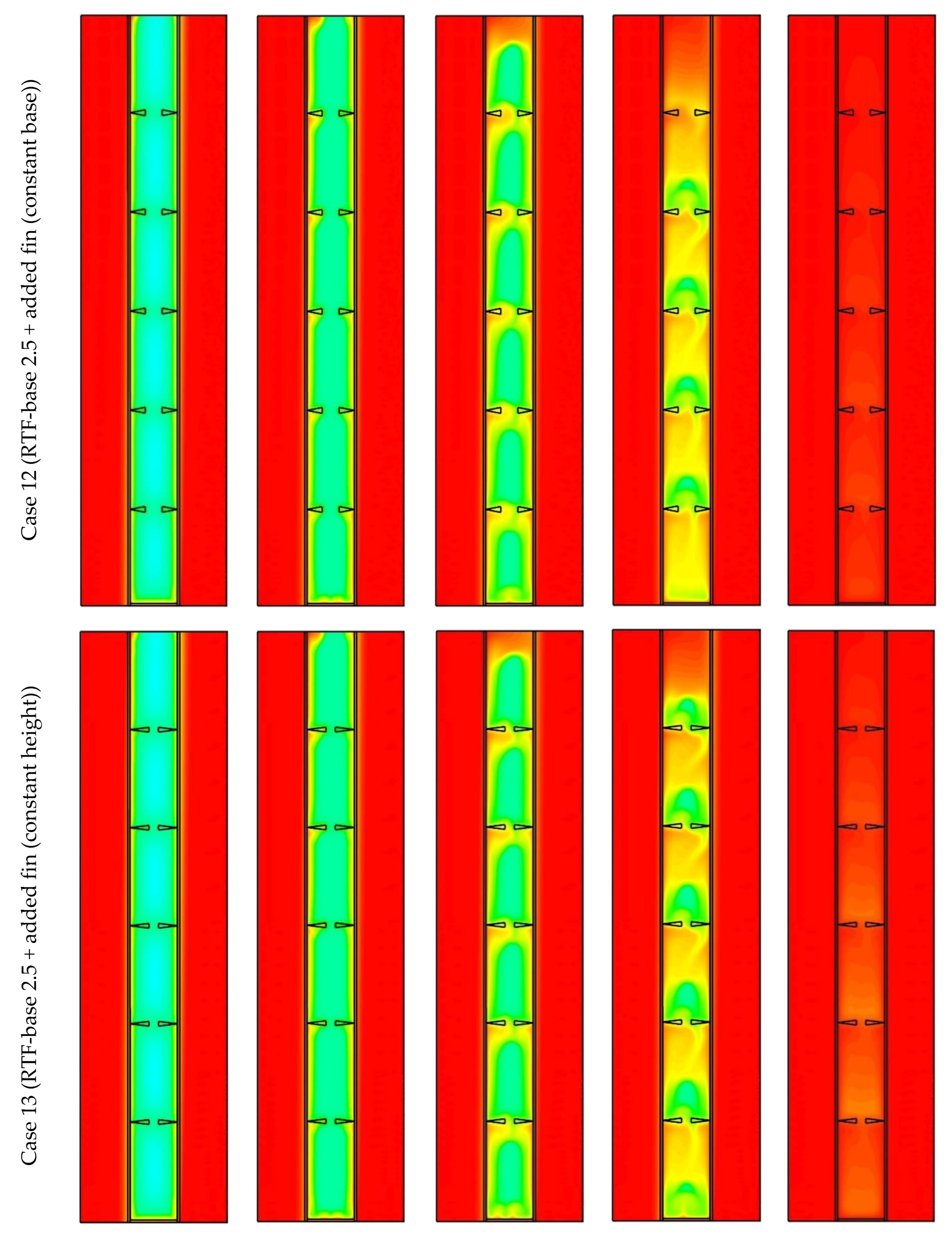
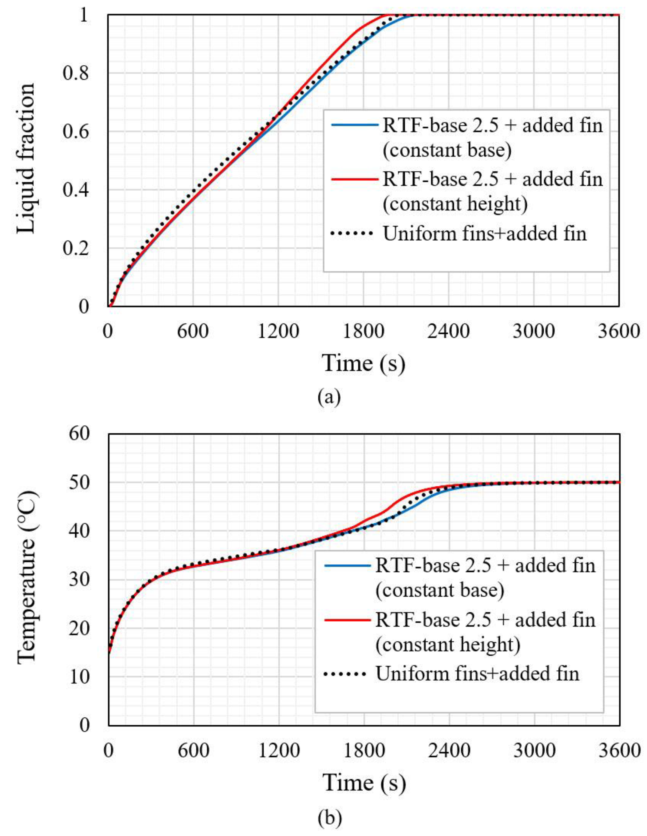
5.5. Investigating the Effects of the Fin Added at the Bottom of the Heat Exchanger on the Charging Process of the PCM

To reduce the melting time of the PCM, a flat fin is added to the bottom of the system because, as shown for the systems without the added fin, a portion of the solid part remained at the bottom of the heat storage unit. Two scenarios are considered for the RTF-base 2.5 case as the best model with an added fin. Like the first scenario, a constant value for the base of the reverse triangular fin is considered (2.5 mm) and the height of the triangular fin is then determined to have the same area of the uniform finned case with an added fin. In the second scenario, the height is supposed to be 8 mm, and the base value is calculated accordingly (the base value is obtained at 2 mm). It should be noted that the effects of adding a flat fin at the bottom of the heat exchanger are studied, which was approved in the previously published papers as a noticeable method [57]. Figure 13 shows the melting process of cases 3, 12, and 13. Case 3 stands for the uniform-fin case with an added fin at the bottom. The reversed triangular fin (2.5 mm (base) × 6.4 mm (height)) with an added fin to the bottom is case 12, while case 13 shows the reversed triangular fin (2 mm (base) × 8 mm (height)) with an added fin to the bottom of the unit. The first row of Figure 13 shows the liquid fraction contours of case 3 at various times. The PCM is melted in the areas around the fins, adjacent to the HTF channel’s wall, and over the flat fin. The molten area expands gradually, and it is worth mentioning that the solid part cannot be accumulated at the bottom of the unit due to the existence of the flat fin. The second row of Figure 13 shows the melting process of case 12. Within the 1800 s, the PCM totally melts at the lower and the higher zones due to the existence of the flat fin added at the bottom and the circulation occurred through the zones via the wide distance existed between the opposite fins compared with case 13. The third row shows the liquid fraction contours of case 13, which has the longest fin and the smallest gap between the opposite fins. The solid part remains at the top, as well as the bottom zones of the system within 1800 s.
Generally, case 13 shows higher performance, and this is clear from Figure 14, which illustrates the temperature distribution of the system at different times. Within 600 s, the average temperatures of all these cases were approximately the same because of the effects of the conduction process in all cases. The temperature increases around the fins, in the areas adjacent to the wall, and in the flat fin at the bottom. The top section of the system reaches the thermal equilibrium early, then this expands to deeper regions of the PCM. In case 13, the harmonic circulation of melted PCM can be seen in the separate zones and through the entire body system.
Figure 15a illustrates the liquid fraction variations of cases 3, 12, and 13 versus time. Figure 15a shows that all the cases have approximately a similar behavior while case 13 benefits from a slight advantage over the other cases. It should be noted that case 13 has the longest fin, and, consequently, the highest surface area of the heat transfer. The average temperatures of the PCM for cases 3, 12, and 13 are also observed in Figure 15b. It is shown that case 13 reaches the thermal equilibrium earlier compared with that of the other cases. From the curves of the liquid fraction and the temperature distribution of cases 3, 12, and 13, it is clear that the thermal behaviors of the studied cases are similar, since the fins are attached to the wall and the flat fin is added to the bottom of the unit. However, small differences are observed, which can be attributed to the fins’ shape.
Table 6 shows the values of the melting time and the heat storage rate of cases 3, 12, and 13. Case 13, having the lowest melting time (1978 s) and the highest heat storage rate (81.5 W), benefits from an advantage over cases 3 and 12. It should be noted that the total melting times of cases 3 and 12 increase by 4.0 and 10.1%, respectively, compared with that of case 13. Furthermore, the heat storage rates of cases 3 and 12 reduce by 4.5 and 8.5%, respectively, compared with that of case 13.

6. Conclusions

In this paper, the impacts of various orientations and dimensions of triangular fins on the charging process of a vertical finned triple-tube PCM heat storage system were studied. Triangular fins were installed on the inner and outer sides of the pipe inside the middle tube in two different ways: (1) the base of the triangular fins was connected to the pipe; (2) the pointed part of the triangular fins was attached to the pipe while the base of the fin was located inside the PCM domain. After finding the best case, a rectangular fin was added to the bottom of the heat storage unit to enhance the heat transfer rate and its thermal performance was compared with that of the uniform-fin case with an added fin at the bottom. The following results were achieved as follows:
  • The slope of the sides of the triangular fins has a determinant role in the circulation of the PCM inside the heat storage unit.
  • The case with the lowest slope (case with the highest fins height) provided a better barrier to keep the PCM inside the zone between two pairs of neighbor fins, while the case with the shortest fin height accelerated the PCM circulation through the zones.
  • The case with the highest height of the fins, and thus the lowest base, experienced the fastest phase change process due to having the largest surface area of the fin.
  • The reverse triangular fin provided a strong barrier against transferring the molten PCM through the zone, which slightly accelerated the melting process and improved the thermal storage rate.
  • The case with reverse triangular fins and the highest height showed higher performance compared with the other cases, since 98.8% of the entire zone was melted, except the region at the bottom of the unit.
  • Adding a rectangular fin to the bottom of the heat exchange with reverse triangular fins and the highest height was selected as the best model, resulting in the lowest melting time (1978 s) and the highest heat storage rate (81.5 W).
For future studies, the authors plan to investigate a wider range of studied parameters, the effects of the utilized materials, and the orientation of the tubes. Moreover, with the help of additive manufacturing, the authors are planning to fabricate the studied geometry and experimentally investigate the tringle twisted fin effects.

Author Contributions

Conceptualization, F.T.N. and S.K.; methodology, F.T.N., S.K.; software, F.T.N. and H.I.M.; validation, H.I.M. and F.A.A.-Q.; formal analysis, F.T.N., S.K., H.I.M., A.D., A.M.A., R.K.I., F.A.A.-Q., M.Z.M., J.A. and W.P.; investigation, F.T.N., S.K., H.I.M., A.D., A.M.A., R.K.I., F.A.A.-Q., M.Z.M., J.A. and W.P.; resources, J.A. and W.P.; writing—original draft preparation, F.T.N., S.K., H.I.M., A.D., A.M.A., R.K.I., F.A.A.-Q., M.Z.M., J.A. and W.P.; writing—review and editing, F.T.N., S.K., H.I.M., A.D., A.M.A., R.K.I., F.A.A.-Q., M.Z.M., J.A. and W.P.; visualization, F.T.N. and S.K.; supervision, S.K. All authors have read and agreed to the published version of the manuscript.

Funding

This research received no external funding.

Institutional Review Board Statement

Not applicable.

Informed Consent Statement

Not applicable.

Data Availability Statement

Not applicable.

Conflicts of Interest

The authors declare no conflict of interest.

Nomenclature

A m Mushy zone constantGreek symbols
C p (J kg−1 K−1)Specific heat λ Liquid fraction
E (J)Heat storage β (K−1)Thermal expansion
g   (m s−2)Gravity ρ (kg m−3)PCM Density
k (W m−1 K−1)Effective thermal conductivity Δ H (J kg−1)PCM Latent heat
L f (J kg−1)Latent heat of fusion μ (m2·s−1)Viscosity
P (kg m−1 s−2)PressureAbbreviation
S (kg m−1 s−2)Source termTESThermal energy storage
t (s)Time PCMPhase change materials
T (°C)Temperature LHSLatent heat storage
T f   (°C)Air temperature HTFHeat transfer fluid
T s   (°C)Solid temperature LHTESLatent heat thermal energy storage
T L i q u i d u s   (°C)Liquidus temperature TTHXTriple tube heat exchanger
T S o l i d u s   (°C)Solidus temperature
V (m/s)Velocity

References

  1. Yang, Y.; Wang, Y.; Zheng, C.; Lin, H.; Xu, R.; Zhu, H.; Bao, L.; Xu, X. Lanthanum carbonate grafted ZSM-5 for superior phosphate uptake: Investigation of the growth and adsorption mechanism. Chem. Eng. J. 2022, 430, 133166. [Google Scholar] [CrossRef]
  2. Jiang, C.; Zheng, Y.; Wang, D.; Zheng, Y.; Xie, C.; Shi, L.; Liu, Z.; Tang, Y. Unusual Size Effect in Ion and Charge Transport in Micron-sized Particulate Aluminum Anodes of Lithium-ion Batteries. Angew. Chem. Int. Ed. 2022, e202208370. [Google Scholar] [CrossRef]
  3. Yang, M.; Li, C.; Zhang, Y.; Jia, D.; Zhang, X.; Hou, Y.; Li, R.; Wang, J. Maximum undeformed equivalent chip thickness for ductile-brittle transition of zirconia ceramics under different lubrication conditions. Int. J. Mach. Tools Manuf. 2017, 122, 55–65. [Google Scholar] [CrossRef]
  4. Bai, B.; Zhou, R.; Cai, G.; Hu, W.; Yang, G. Coupled thermo-hydro-mechanical mechanism in view of the soil particle rearrangement of granular thermodynamics. Comput. Geotech. 2021, 137, 104272. [Google Scholar] [CrossRef]
  5. Hassan, F.; Jamil, F.; Hussain, A.; Ali, H.M.; Janjua, M.M.; Khushnood, S.; Farhan, M.; Altaf, K.; Said, Z.; Li, C. Recent advancements in latent heat phase change materials and their applications for thermal energy storage and buildings: A state of the art review. Sustain. Energy Technol. Assess. 2022, 49, 101646. [Google Scholar] [CrossRef]
  6. Romdhane, S.B.; Amamou, A.; Khalifa, R.B.; Said, N.M.; Younsi, Z.; Jemni, A. A review on thermal energy storage using phase change materials in passive building applications. J. Build. Eng. 2020, 32, 101563. [Google Scholar] [CrossRef]
  7. Jarvinen, J.; Goldsworthy, M.; White, S.; Pudney, P.; Belusko, M.; Bruno, F. Evaluating the utility of passive thermal storage as an energy storage system on the Australian energy market. Renew. Sustain. Energy Rev. 2021, 137, 110615. [Google Scholar] [CrossRef]
  8. Li, B.; Li, C.; Zhang, Y.; Wang, Y.; Jia, D.; Yang, M. Grinding temperature and energy ratio coefficient in MQL grinding of high-temperature nickel-base alloy by using different vegetable oils as base oil. Chin. J. Aeronaut. 2016, 29, 1084–1095. [Google Scholar] [CrossRef]
  9. Gong, S.; Sheng, X.; Li, X.; Sheng, M.; Wu, H.; Lu, X.; Qu, J. A Multifunctional Flexible Composite Film with Excellent Multi-Source Driven Thermal Management, Electromagnetic Interference Shielding, and Fire Safety Performance, Inspired by a “Brick–Mortar” Sandwich Structure. Adv. Funct. Mater. 2022, 32, 2200570. [Google Scholar] [CrossRef]
  10. Zhang, X.; Tang, Y.; Zhang, F.; Lee, C.S. A novel aluminum–graphite dual-ion battery. Adv. Energy Mater. 2016, 6, 1502588. [Google Scholar] [CrossRef]
  11. Zhang, G.; Chen, J.; Zhang, Z.; Sun, M.; Yu, Y.; Wang, J.; Cai, S. Analysis of magnetorheological clutch with double cup-shaped gap excited by Halbach array based on finite element method and experiment. Smart Mater. Struct. 2022, 31, 075008. [Google Scholar] [CrossRef]
  12. Wu, X.; Li, C.; Zhou, Z.; Nie, X.; Chen, Y.; Zhang, Y.; Cao, H.; Liu, B.; Zhang, N.; Said, Z. Circulating purification of cutting fluid: An overview. Int. J. Adv. Manuf. Technol. 2021, 117, 2565–2600. [Google Scholar] [CrossRef] [PubMed]
  13. Feng, Y.; Li, H.; Li, L.; Bu, L.; Wang, T. Numerical investigation on the melting of nanoparticle-enhanced phase change materials (NEPCM) in a bottom-heated rectangular cavity using lattice Boltzmann method. Int. J. Heat Mass Transf. 2015, 81, 415–425. [Google Scholar] [CrossRef]
  14. Zhang, G.; Zhang, Z.; Sun, M.; Yu, Y.; Wang, J.; Cai, S. The influence of the temperature on the dynamic behaviors of magnetorheological gel. Adv. Eng. Mater. 2022, 2101680. [Google Scholar] [CrossRef]
  15. Ajarostaghi, S.S.M.; Delavar, M.A.; Dolati, A. Numerical investigation of melting process in horizontal shell-and-tube phase change material storage considering different HTF channel geometries. Heat Transf. Res. 2017, 48, 1515–1529. [Google Scholar] [CrossRef]
  16. Jegadheeswaran, S.; Pohekar, S.D. Performance enhancement in latent heat thermal storage system: A review. Renew. Sustain. Energy Rev. 2009, 13, 2225–2244. [Google Scholar]
  17. Rahimi, M.; Ranjbar, A.; Ganji, D.; Sedighi, K.; Hosseini, M. Experimental investigation of phase change inside a finned-tube heat exchanger. J. Eng. 2014, 2014, 641954. [Google Scholar] [CrossRef]
  18. Hosseini, M.; Rahimi, M.; Bahrampoury, R. Thermal analysis of PCM containing heat exchanger enhanced with normal annular fines. Mech. Sci. 2015, 6, 221–234. [Google Scholar] [CrossRef]
  19. Jayaprakash, M.; Alzahrani, H.A.; Sowmya, G.; Kumar, R.V.; Malik, M.; Alsaiari, A.; Prasannakumara, B. Thermal distribution through a moving longitudinal trapezoidal fin with variable temperature-dependent thermal properties using DTM-Pade approximant. Case Stud. Therm. Eng. 2021, 28, 101697. [Google Scholar] [CrossRef]
  20. Wang, F.; Kumar, R.V.; Sowmya, G.; El-Zahar, E.R.; Prasannakumara, B.; Khan, M.I.; Khan, S.U.; Malik, M.; Xia, W.-F. LSM and DTM-Pade approximation for the combined impacts of convective and radiative heat transfer on an inclined porous longitudinal fin. Case Stud. Therm. Eng. 2022, 35, 101846. [Google Scholar] [CrossRef]
  21. Algarni, M.; Alazwari, M.A.; Safaei, M.R. Optimization of Nano-Additive Characteristics to Improve the Efficiency of a Shell and Tube Thermal Energy Storage System Using a Hybrid Procedure: DOE, ANN, MCDM, MOO, and CFD Modeling. Mathematics 2021, 9, 3235. [Google Scholar]
  22. Ju, Y.; Zhu, T.; Mashayekhi, R.; Mohammed, H.I.; Khan, A.; Talebizadehsardari, P.; Yaïci, W. Evaluation of Multiple Semi-Twisted Tape Inserts in a Heat Exchanger Pipe Using Al2O3 Nanofluid. Nanomaterials 2021, 11, 1570. [Google Scholar] [CrossRef] [PubMed]
  23. Chu, Y.-M.; Nazir, U.; Sohail, M.; Selim, M.M.; Lee, J.-R. Enhancement in thermal energy and solute particles using hybrid nanoparticles by engaging activation energy and chemical reaction over a parabolic surface via finite element approach. Fractal Fract. 2021, 5, 119. [Google Scholar] [CrossRef]
  24. Gao, T.; Zhang, Y.; Li, C.; Wang, Y.; An, Q.; Liu, B.; Said, Z.; Sharma, S. Grindability of carbon fiber reinforced polymer using CNT biological lubricant. Sci. Rep. 2021, 11, 22535. [Google Scholar] [PubMed]
  25. El Hasadi, Y.M.; Khodadadi, J. Numerical simulation of the effect of the size of suspensions on the solidification process of nanoparticle-enhanced phase change materials. J. Heat Transf. 2013, 135, 052901. [Google Scholar] [CrossRef]
  26. Zhang, J.; Li, C.; Zhang, Y.; Yang, M.; Jia, D.; Liu, G.; Hou, Y.; Li, R.; Zhang, N.; Wu, Q. Experimental assessment of an environmentally friendly grinding process using nanofluid minimum quantity lubrication with cryogenic air. J. Clean. Prod. 2018, 193, 236–248. [Google Scholar] [CrossRef]
  27. Ghalambaz, M.; Mehryan, S.; Hajjar, A.; Veismoradi, A. Unsteady natural convection flow of a suspension comprising Nano-Encapsulated Phase Change Materials (NEPCMs) in a porous medium. Adv. Powder Technol. 2020, 31, 954–966. [Google Scholar]
  28. Ho, C.; Liu, Y.-C.; Ghalambaz, M.; Yan, W.-M. Forced convection heat transfer of Nano-Encapsulated Phase Change Material (NEPCM) suspension in a mini-channel heatsink. Int. J. Heat Mass Transf. 2020, 155, 119858. [Google Scholar] [CrossRef]
  29. Zhang, Y.; Pan, Z.; Yang, J.; Chen, J.; Chen, K.; Yan, K.; Meng, X.; Zhang, X.; He, M. Study on the suppression mechanism of (NH4)2CO3 and SiC for polyethylene deflagration based on flame propagation and experimental analysis. Powder Technol. 2022, 399, 117193. [Google Scholar]
  30. Wang, Y.; Li, C.; Zhang, Y.; Yang, M.; Li, B.; Dong, L.; Wang, J. Processing characteristics of vegetable oil-based nanofluid MQL for grinding different workpiece materials. Int. J. Precis. Eng. Manuf. Green Technol. 2018, 5, 327–339. [Google Scholar]
  31. Zhou, S.-S.; Almarashi, A.; Talabany, Z.J.; Selim, M.M.; Issakhov, A.; Li, Y.-M.; Yao, S.-W.; Li, Z. Augmentation of performance of system with dispersion of nanoparticles inside PCM. J. Mol. Liq. 2021, 333, 115921. [Google Scholar]
  32. Guo, J.; Du, Z.; Liu, G.; Yang, X.; Li, M.-J. omprCession effect of metal foam on melting phase change in a shell-and-tube unit. Appl. Therm. Eng. 2022, 206, 118124. [Google Scholar] [CrossRef]
  33. Sardari, P.T.; Grant, D.; Giddings, D.; Walker, G.S.; Gillott, M. Composite metal foam/PCM energy store design for dwelling space air heating. Energy Convers. Manag. 2019, 201, 112151. [Google Scholar]
  34. Cheng, Z.; Guo, Z.; Fu, P.; Yang, J.; Wang, Q. New insights into the effects of methane and oxygen on heat/mass transfer in reactive porous media. Int. Commun. Heat Mass Transf. 2021, 129, 105652. [Google Scholar] [CrossRef]
  35. Jia, D.; Zhang, Y.; Li, C.; Yang, M.; Gao, T.; Said, Z.; Sharma, S. Lubrication-enhanced mechanisms of titanium alloy grinding using lecithin biolubricant. Tribol. Int. 2022, 169, 107461. [Google Scholar] [CrossRef]
  36. Chu, Y.M.; Bashir, S.; Ramzan, M.; Malik, M.Y. Model-based comparative study of magnetohydrodynamics unsteady hybrid nanofluid flow between two infinite parallel plates with particle shape effects. Math. Methods Appl. Sci. 2022, 1–15. [Google Scholar] [CrossRef]
  37. Sowmya, G.; Varun Kumar, R.S.; Alsulami, M.D.; Prasannakumara, B.C. Thermal stress and temperature distribution of an annular fin with variable temperature-dependent thermal properties and magnetic field using DTM-Pade approximant. Waves Random Complex Media 2022, 1–29. [Google Scholar] [CrossRef]
  38. Baslem, A.; Sowmya, G.; Gireesha, B.J.; Prasannakumara, B.C.; Rahimi-Gorji, M.; Hoang, N.M. Analysis of thermal behavior of a porous fin fully wetted with nanofluids: Convection and radiation. J. Mol. Liq. 2020, 307, 112920. [Google Scholar] [CrossRef]
  39. Sowmya, G.; Gireesha, B.J.; Sindhu, S.; Prasannakumara, B.C. Investigation of Ti6Al4V and AA7075 alloy embedded nanofluid flow over longitudinal porous fin in the presence of internal heat generation and convective condition. Commun. Theor. Phys. 2020, 72, 025004. [Google Scholar] [CrossRef]
  40. Yang, X.; Guo, J.; Yang, B.; Cheng, H.; Wei, P.; He, Y.-L. Design of non-uniformly distributed annular fins for a shell-and-tube thermal energy storage unit. Appl. Energy 2020, 279, 115772. [Google Scholar] [CrossRef]
  41. Guo, J.; Wang, X.; Yang, B.; Yang, X.; Li, M.-J. Thermal assessment on solid-liquid energy storage tube packed with non-uniform angled fins. Sol. Energy Mater. Sol. Cells 2022, 236, 111526. [Google Scholar] [CrossRef]
  42. Yang, X.; Wang, X.; Liu, Z.; Luo, X.; Yan, J. Effect of fin number on the melting phase change in a horizontal finned shell-and-tube thermal energy storage unit. Sol. Energy Mater. Sol. Cells 2022, 236, 111527. [Google Scholar] [CrossRef]
  43. Yang, M.; Li, C.; Said, Z.; Zhang, Y.; Li, R.; Debnath, S.; Ali, H.M.; Gao, T.; Long, Y. Semiempirical heat flux model of hard-brittle bone material in ductile microgrinding. J. Manuf. Processes 2021, 71, 501–514. [Google Scholar]
  44. Al-Abidi, A.A.; Mat, S.; Sopian, K.; Sulaiman, M.; Mohammad, A.T. Numerical study of PCM solidification in a triplex tube heat exchanger with internal and external fins. Int. J. Heat Mass Transf. 2013, 61, 684–695. [Google Scholar] [CrossRef]
  45. Abdulateef, A.M.; Mat, S.; Sopian, K.; Abdulateef, J.; Gitan, A.A. Experimental and computational study of melting phase-change material in a triplex tube heat exchanger with longitudinal/triangular fins. Sol. Energy 2017, 155, 142–153. [Google Scholar] [CrossRef]
  46. Guo, J.; Liu, Z.; Yang, B.; Yang, X.; Yan, J. Melting assessment on the angled fin design for a novel latent heat thermal energy storage tube. Renew. Energy 2022, 183, 406–422. [Google Scholar] [CrossRef]
  47. Senthil, R.; Patel, A.; Rao, R.; Ganeriwal, S. Melting Behavior of Phase Change Material in a Solar Vertical Thermal Energy Storage with Variable Length Fins added on the Heat Transfer Tube Surfaces. Int. J. Renew. Energy Dev. 2020, 9, 361–367. [Google Scholar] [CrossRef]
  48. Mahdi, J.M.; Lohrasbi, S.; Ganji, D.D.; Nsofor, E.C. Accelerated melting of PCM in energy storage systems via novel configuration of fins in the triplex-tube heat exchanger. Int. J. Heat Mass Transf. 2018, 124, 663–676. [Google Scholar]
  49. Abdulateef, A.M.; Abdulateef, J.; Sopian, K.; Mat, S.; Ibrahim, A. Optimal fin parameters used for enhancing the melting and solidification of phase-change material in a heat exchanger unite. Case Stud. Therm. Eng. 2019, 14, 100487. [Google Scholar] [CrossRef]
  50. Chu, Y.-M.; Shankaralingappa, B.; Gireesha, B.; Alzahrani, F.; Khan, M.I.; Khan, S.U. Combined impact of Cattaneo-Christov double diffusion and radiative heat flux on bio-convective flow of Maxwell liquid configured by a stretched nano-material surface. Appl. Math. Comput. 2022, 419, 126883. [Google Scholar]
  51. Sun, X.; Mohammed, H.I.; Tiji, M.E.; Mahdi, J.M.; Majdi, H.S.; Wang, Z.; Talebizadehsardari, P.; Yaïci, W. Investigation of Heat Transfer Enhancement in a Triple TUBE Latent Heat Storage System Using Circular Fins with Inline and Staggered Arrangements. Nanomaterials 2021, 11, 2647. [Google Scholar] [CrossRef] [PubMed]
  52. Sivalakshmi, S.; Raja, M.; Gowtham, G. Effect of helical fins on the performance of a double pipe heat exchanger. Mater. Today Proc. 2021, 43, 1128–1131. [Google Scholar] [CrossRef]
  53. Abdulateef, A.M.; Jaszczur, M.; Hassan, Q.; Anish, R.; Niyas, H.; Sopian, K.; Abdulateef, J. Enhancing the melting of phase change material using a fins–nanoparticle combination in a triplex tube heat exchanger. J. Energy Storage 2021, 35, 102227. [Google Scholar] [CrossRef]
  54. Safari, V.; Abolghasemi, H.; Kamkari, B. Experimental and numerical investigations of thermal performance enhancement in a latent heat storage heat exchanger using bifurcated and straight fins. Renew. Energy 2021, 174, 102–121. [Google Scholar]
  55. Masoumpour-Samakoush, M.; Miansari, M.; Ajarostaghi, S.S.M.; Arıcı, M. Impact of innovative fin combination of triangular and rectangular fins on melting process of phase change material in a cavity. J. Energy Storage 2022, 45, 103545. [Google Scholar]
  56. Ghalambaz, M.; Mehryan, S.; Mahdavi, M.; Younis, O.; Alim, M.A. Evaluation of the melting performance in a conical latent heat thermal unit having variable length fins. Sustainability 2021, 13, 2667. [Google Scholar]
  57. Najim, F.T.; Mohammed, H.I.; Al-Najjar, H.M.T.; Thangavelu, L.; Mahmoud, M.Z.; Mahdi, J.M.; Tiji, M.E.; Yaïci, W.; Talebizadehsardari, P. Improved Melting of Latent Heat Storage Using Fin Arrays with Non-Uniform Dimensions and Distinct Patterns. Nanomaterials 2022, 12, 403. [Google Scholar] [CrossRef]
  58. Punniakodi, B.M.S.; Senthil, R. A review on container geometry and orientations of phase change materials for solar thermal systems. J. Energy Storage 2021, 36, 102452. [Google Scholar] [CrossRef]
  59. Li, Z.; Shahsavar, A.; Al-Rashed, A.A.; Talebizadehsardari, P. Effect of porous medium and nanoparticles presences in a counter-current triple-tube composite porous/nano-PCM system. Appl. Therm. Eng. 2020, 167, 114777. [Google Scholar] [CrossRef]
  60. Wang, P.; Wang, X.; Huang, Y.; Li, C.; Peng, Z.; Ding, Y. Thermal energy charging behaviour of a heat exchange device with a zigzag plate configuration containing multi-phase-change-materials (m-PCMs). Appl. Energy 2015, 142, 328–336. [Google Scholar] [CrossRef]
  61. Esapour, M.; Hosseini, M.; Ranjbar, A.; Pahamli, Y.; Bahrampoury, R. Phase change in multi-tube heat exchangers. Renew. Energy 2016, 85, 1017–1025. [Google Scholar] [CrossRef]
  62. Mat, S.; Al-Abidi, A.A.; Sopian, K.; Sulaiman, M.; Mohammad, A.T. Enhance heat transfer for PCM melting in triplex tube with internal–external fins. Energy Convers. Manag. 2013, 74, 223–236. [Google Scholar] [CrossRef]
Figure 1. The schematic of the proposed systems, including the no-fin case, uniform-fin case, triangular finned (TF) case, reverse triangular finned (RTF) case, and RTF case with added fin.
Sustainability 14 10982 g001
Figure 2. Variations of liquid fraction versus time for various cell numbers.
Sustainability 14 10982 g002
Figure 3. Comparing the numerical results of the present study, including the overall temperature and liquid fraction values of the PCM, with those of [62].
Sustainability 14 10982 g003
Figure 4. Liquid fraction development for cases 4 to 7 at various times.
Sustainability 14 10982 g004aSustainability 14 10982 g004bSustainability 14 10982 g004c
Figure 5. Temperature distribution development for cases 4 to 7 at various times.
Sustainability 14 10982 g005aSustainability 14 10982 g005bSustainability 14 10982 g005c
Figure 6. (a) melting fraction and (b) mean temperature of the PCM for different base dimensions of the fins (cases 4 to 7) (considering the best positions and the fixed cross-section of 10 mm2).
Sustainability 14 10982 g006
Figure 7. Liquid fraction development for cases 8 to 11 at various times.
Sustainability 14 10982 g007aSustainability 14 10982 g007bSustainability 14 10982 g007c
Figure 8. Temperature distribution development for cases 8 to 11 at various times.
Sustainability 14 10982 g008aSustainability 14 10982 g008bSustainability 14 10982 g008c
Figure 9. Streamline development for cases 4 and 8 at various times.
Sustainability 14 10982 g009
Figure 10. (a) melting fraction and (b) mean temperature of the PCM for different dimensions of the fins (Cases 8 to 11) (considering the best positions and the fixed cross-section of 10 mm2).
Sustainability 14 10982 g010
Figure 11. Liquid fraction development for cases 8, 1, and 2 at various times.
Sustainability 14 10982 g011aSustainability 14 10982 g011b
Figure 12. (a) melting fraction and (b) mean temperature for different cases (Cases 1, 2, and 8) (considering the fixed cross-section of 10 mm2 and the best positions for the fins).
Sustainability 14 10982 g012
Figure 13. Liquid fraction development of cases 3, 12, and 13 at various times.
Sustainability 14 10982 g013aSustainability 14 10982 g013b
Figure 14. Temperature distribution of cases 3, 12, and 13 at various times.
Sustainability 14 10982 g014aSustainability 14 10982 g014b
Figure 15. (a) melting fraction and (b) mean temperature of the PCM for various cases (cases 3, 12, and 13) (considering the fixed cross-section of 10 mm2 and the best positions for the fins).
Sustainability 14 10982 g015
Table 1. Fins dimensions of the studied cases including the no-fin, uniform-fin, triangular finned (TF), reverse triangular finned (RTF) cases, and RTF case with an added fin to the bottom of the heat exchanger.
CasesDescriptionTriangle Base/Uniform Fins Width (mm)Triangle Height/Uniform Fins Height (mm)Added Fin Dimensions (mm)
1no-fin---
2uniform-fin25-
3uniform-fin + added fin1.651 × 20
4TF-base 2.52.58-
5TF-base 3.03.06.65-
6TF-base 3.53.55.7-
7TF-base 4.04.05-
8RTF-base 2.52.58-
9RTF-base 3.03.06.65-
10RTF-base 3.53.55.7-
11RTF-base 4.04.05-
12RTF-base 2.5 + added fin (constant base)2.56.41 × 20
13RTF-base 2.5 + added fin (constant height)281 × 20
Table 2. Thermodynamic properties of the PCM used [34].
Properties ρ l
[kg/m3]
ρ s
[kg/m3]
Lf
[kJ/kg]
Cp
[kJ/kg·K]
K
[W/m·K]
µ
[N·s/m2]
TL
[°C]
TS
[°C]
β
[J/K]
Values77086017020.20.02336290.0006
Table 3. Effect of time step size on the melting time for the selected grid.
Number of cells43,000
Value of Time step size (s)0.10.20.4
Melting duration473347274701
Table 4. Melting time and heat storage rate for various cases of triangular fins (cases 4–7), and reverse triangular fins (cases 8–11).
CaseCase 4Case 5Case 6Case 7Case 8Case 9Case 10Case 11
TF-base 2.5TF-base 3.0TF-base 3.5TF-base 4.0RTF-base 2.5RTF-base 3.0RTF-base 3.5RTF-base 4.0
Melting time (s)30603118317632122997314931803209
Heat storage rate (W)55.0153.952.9952.3956.0553.3852.8552.36
Table 5. Melting times and rates of heat storage for cases 1, 2, and 8.
CaseCase 1 (No-Fin)Case 2 (Uniform-Fin)Case 8 (RTF-Base 2.5)
Melting time (s)465430562997
Heat storage rate (W)36.255.156.1
Table 6. Melting times and heat storage rates of cases 3, 12, and 13.
CaseCase 3 (Uniform-Fin + Added Fin)Case 12 (RTF-Base 2.5 + Added Fin (Base Constant))Case 13 (RTF-Base 2.5 + Added Fin (Height Constant))
Melting time (s)205721781978
Heat storage rate (W)77.974.581.5
Publisher’s Note: MDPI stays neutral with regard to jurisdictional claims in published maps and institutional affiliations.

