
Linear Permanent Magnet Vernier Generators for Wave Energy Applications: Analysis, Challenges, and Opportunities


Abstract
:1. Introduction
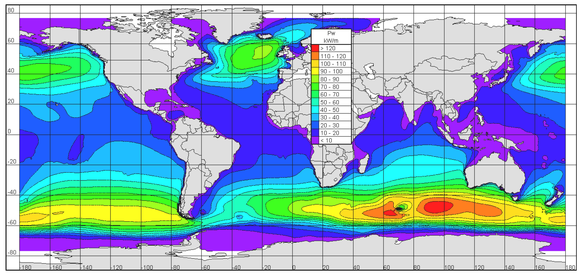
2. Wave Energy Applications
2.1. Wave Energy Converters (WECs)
- oscillating water column;
- overtopping converter;
- oscillating body system.
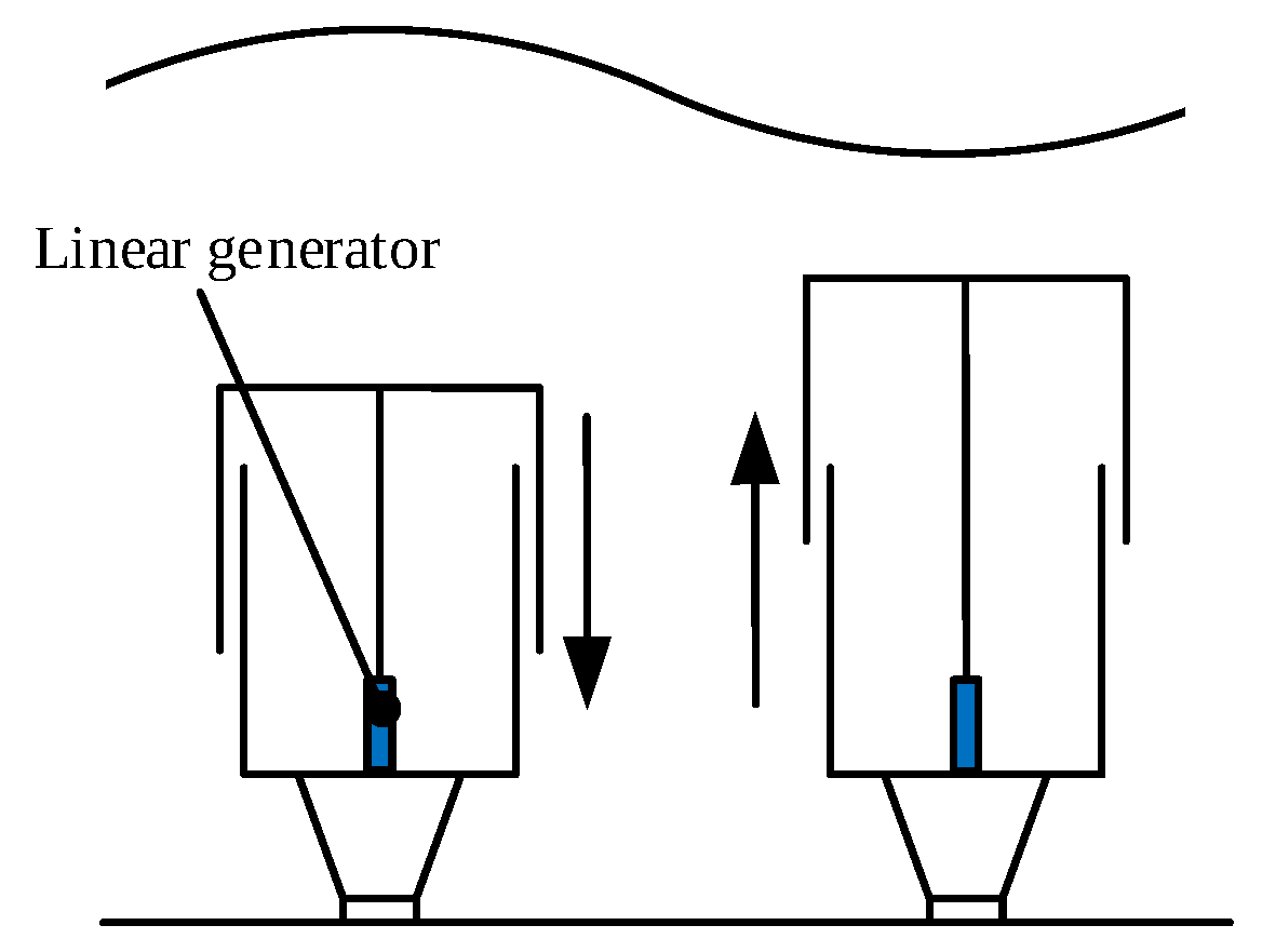
2.1.1. Archimedes Wave Swing WEC
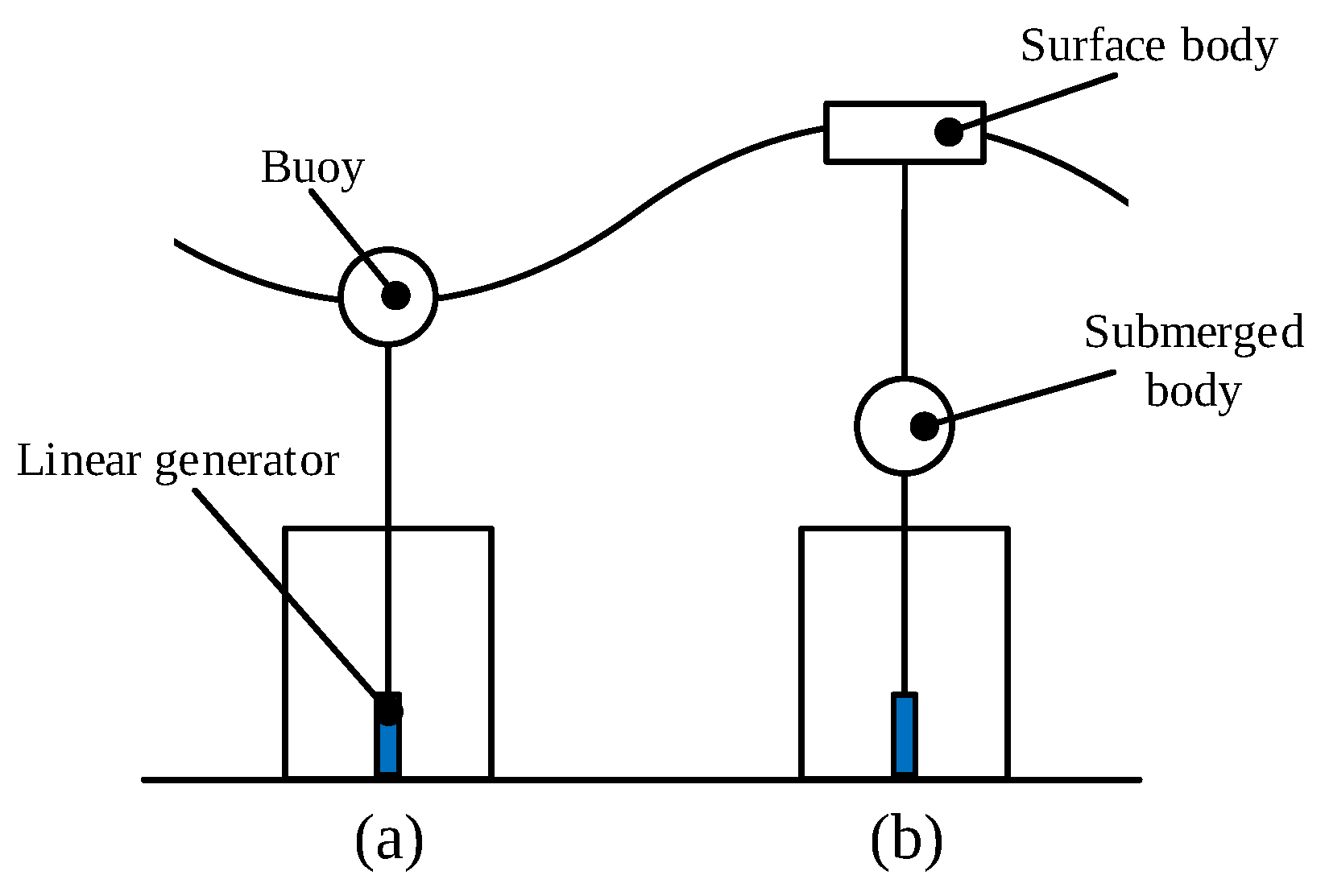
2.1.2. Point Absorber WEC
2.2. Linear Generators
3. Operation Principles and Analysis of Linear PM Vernier Machines
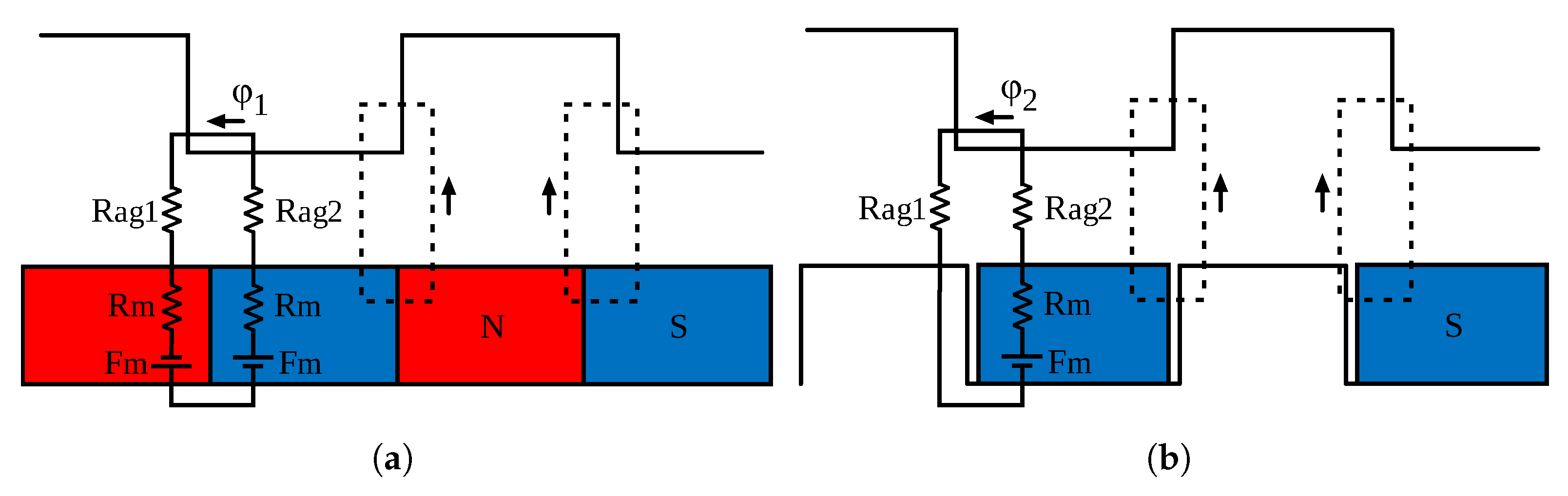
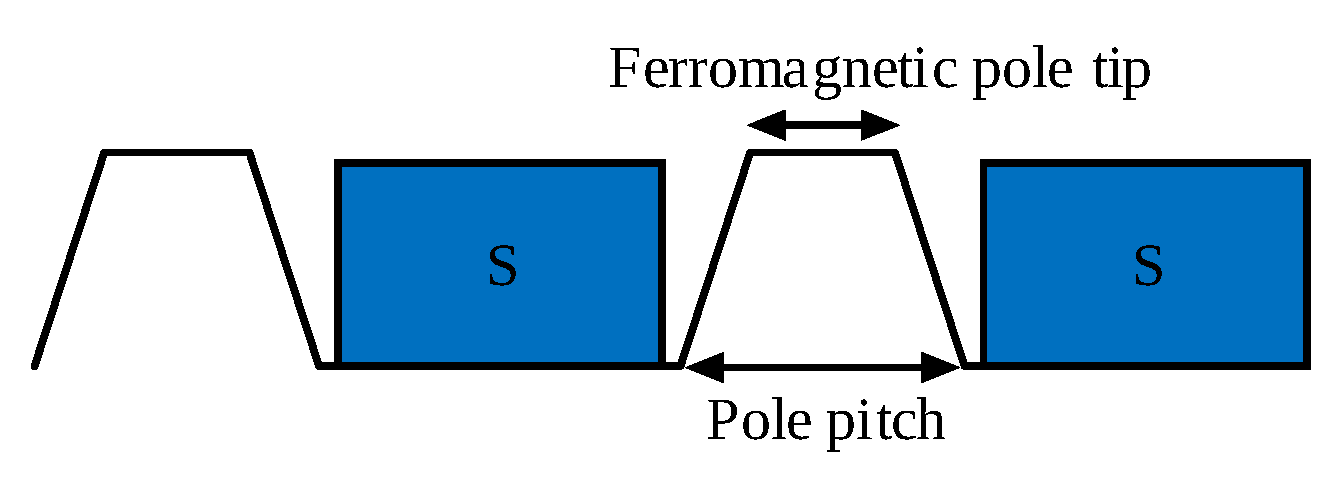
3.1. Magnetic Gearing Effect
- no need for maintenance;
- isolation between the output and input shafts;
- inherent overload protection;
- no mechanical vibration and minimum acoustic noise;
- higher efficiency;
- higher reliability;
- no need for lubrication.
3.2. Analysis and Optimization of Linear PM Vernier Generators
4. Linear Permanent Magnet Vernier Generators (LPMVGs)
- linear flat and tubular;
- long/short stator and short/long translator;
- single-sided and double-sided;
- permanent magnet type;
- armature winding.
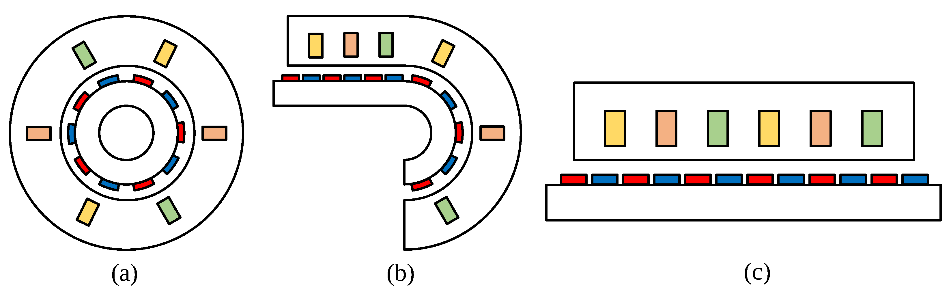
4.1. Flat and Tubular Structures
4.2. Long/Short Stator and Short/Long Translator
4.3. Single-Sided and Double-Sided
4.4. Permanent Magnet Type
- surface-mounted type;
- interior type;
- spoke type;
- halbach/Quasi-Halbach arrays;
- V-type.

4.5. Armature Winding
5. Performance Improvement of Linear PM Vernier Generators
- thrust force capability improvement;
- power factor development;
- thrust force ripple reduction;
- cost reduction.
5.1. Thrust Force Capability Improvement
5.2. Power Factor Development
- optimal magnetic gear ratio;
- appropriate configuration of PMs;
- high-temperature superconducting (HTS) bulks.
5.2.1. Optimal Magnetic Gear Ratio
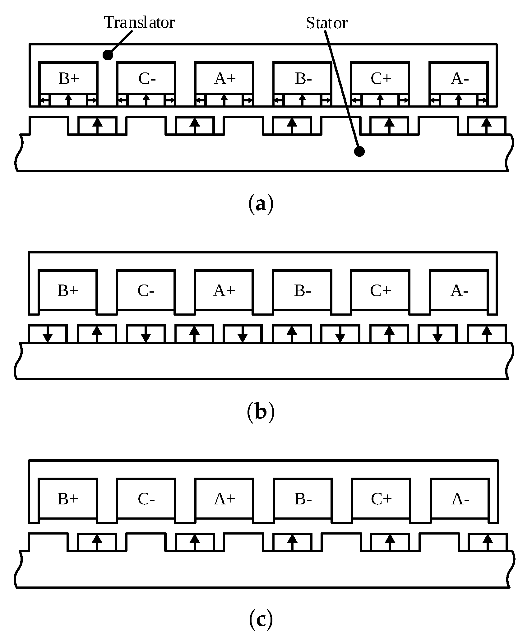
5.2.2. Appropriate Configuration of PMs
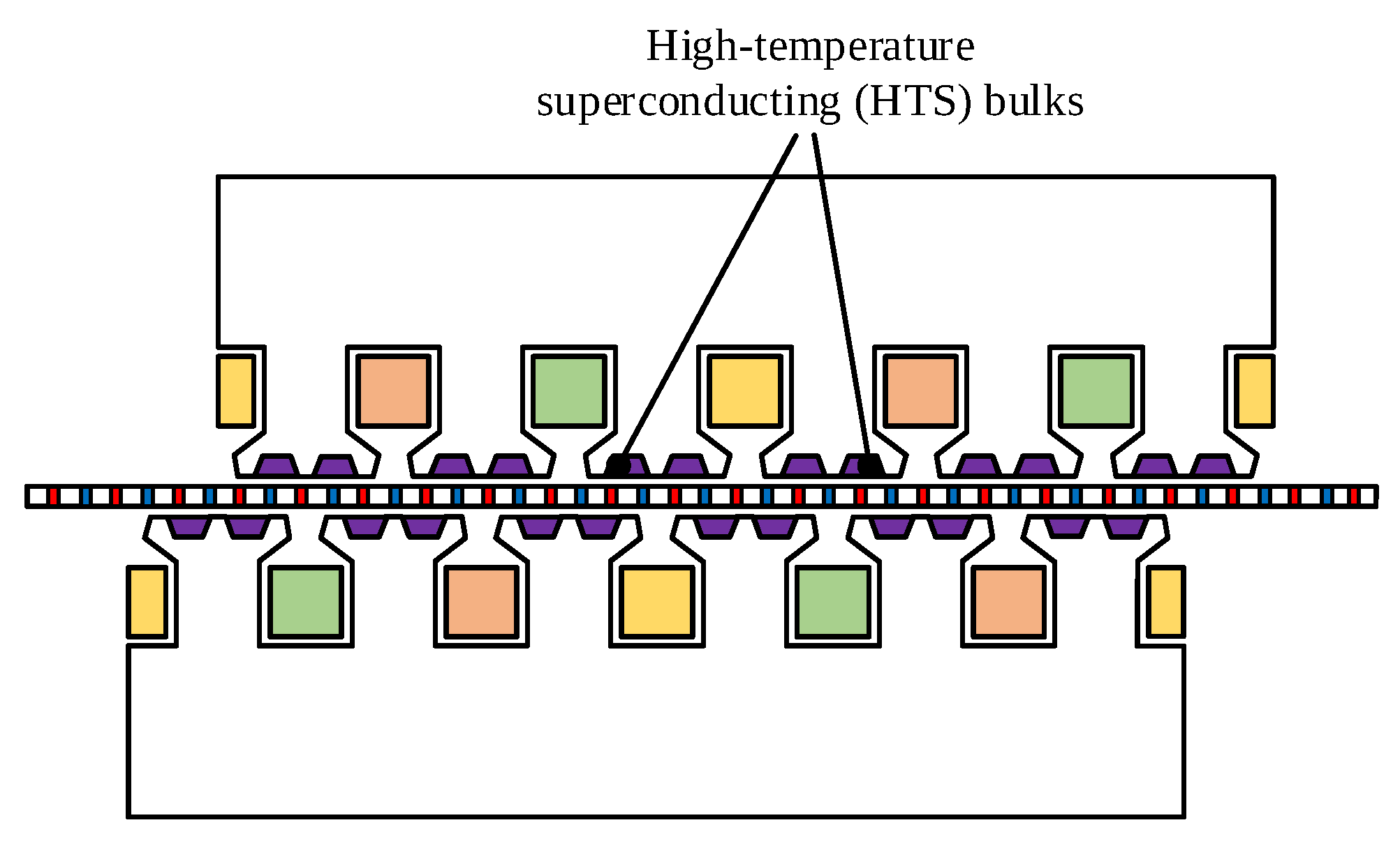
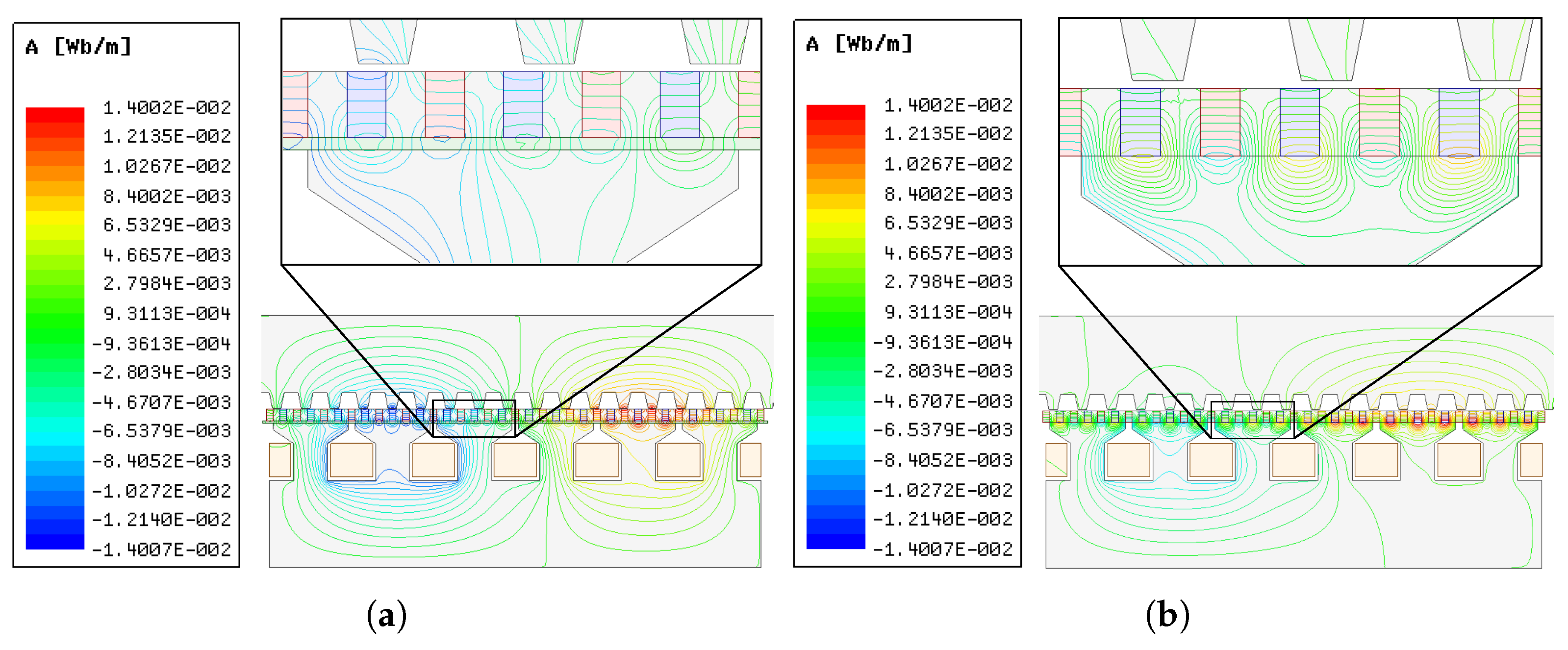
5.2.3. High-Temperature Superconducting (HTS) Bulks
5.3. Thrust Force Ripple Reduction
- linear longitudinal end effect;
- cogging force;
- normal force in the perpendicular direction of reciprocation;
- non-sinusoidal back-EMF.
5.3.1. Linear Longitudinal End Effect
5.3.2. Cogging Force
5.3.3. Normal Force
5.3.4. Non-Sinusoidal Back-EMF
5.4. Cost Reduction
6. Analysis and Comparison of Different Linear PM Vernier Generators
7. Conclusions and Outlooks
- The most considerable disadvantage of linear PM vernier machines is their poor power factor. Innovative techniques are required to further develop the low power factor of linear vernier structures.
- Due to the time-consuming process of analyzing linear PM vernier generators based on FEA, accurate analytical methods are desired to provide analysis models in a short time.
- One of the most important criteria that must be considered into account is the cost of linear PM vernier generators, which are required to be declined by offering more economically viable structures and the decrease of the volume of magnets.
- The reduction of the weight of linear PM vernier generators can be realized by reducing the active material. There are opportunities to employ more lightweight linear generators for wave energy harvesting systems.
- Unconventional topologies can be introduced to improve the performance of linear vernier generators and facilitate their utilization in wave energy applications.
- The unwanted longitudinal end effect of linear PM vernier generators imposes a disadvantageous impact on the machine performance, which is desired to be diminished.
- Thermal analysis of linear PM vernier generators is another interesting subject in which not enough research has been accomplished so far.
- The magnetic gear ratio significantly affects the performance of linear PM vernier generators used in wave energy applications. Analytical and numerical methods are required to investigate the optimal gear ratio values.
- The configuration and number of flux modulation poles can have an impact on the gear ratio and the machine performance, which can be surveyed for linear vernier structures.
- A system-level optimization process is needed to improve the efficiency and performance of a linear vernier generator used in wave energy applications.
- Linear PM vernier machines utilize more number of PMs compared to linear PM synchronous machines; thus, the study on the possibilities to avoid irreversible demagnetization can be very useful.
Author Contributions
Funding
Institutional Review Board Statement
Informed Consent Statement
Data Availability Statement
Conflicts of Interest
Abbreviations
| AWS | Archimedes wave swing |
| CPHPM | Consequent-pole and Halbach permanent magnet |
| DC | Direct current |
| DSSLVM | Dual-stator spoke-type linear vernier machine |
| DSTVM | Dual stator tubular vernier machine |
| EMF | Electromotive force |
| EMN | Equivalent magnetic network |
| FEA | Finite element analysis |
| FMP | Flux modulation pole |
| FP | Fractional pole |
| GCD | Greatest common divisor |
| GR | Gear ratio |
| HTS | High temperature superconducting |
| IMCP | Inset magnet consequent pole |
| LCM | Lowest common multiple |
| LCPSPMVM | Linear consequent pole stator permanent magnet vernier machine |
| LPMSG | Linear permanent magnet synchronous generator |
| LPMSM | Linear permanent magnet synchronous machine |
| LPMVG | Linear permanent magnet vernier generator |
| LPMVM | Linear permanent magnet vernier machine |
| LPPMVM | Linear primary PM vernier machine |
| LSSPMVM | Linear stator spoke-type permanent magnet vernier machine |
| MEC | Magnetic equivalent circuit |
| MMF | Magnetomotive force |
| NdFeB | Neodymium–iron–boron |
| PM | Permanent magnet |
| PTO | Power take-off |
| VCP | V-shaped consequent pole |
| WEC | Wave energy converter |
| YBCO | Yttrium boron copper oxide |
| A | Coefficient defined by the volume of PMs |
| B | Cost coefficient related to the power converter |
| Maximum flux density | |
| Cost of energy | |
| E | Electric field |
| Average thrust force | |
| Maximum of thrust force | |
| Minimum of thrust force | |
| I | Current |
| J | Current density |
| Eddy current loss coefficient | |
| Flux leakage coefficient | |
| Excess loss coefficient | |
| Hysteresis loss coefficient | |
| Electric loading | |
| Winding factor | |
| L | Effective length |
| Synchronous inductance | |
| Stack length | |
| m | Number of phases |
| P | Electromagnetic power |
| p | Number of stator armture winding pole pairs |
| Airgap reluctance of the slot | |
| Airgap reluctance of the tooth | |
| Reluctance of the magne | |
| T | Electrical period |
| Cogging force period | |
| End time | |
| v | Mechanical speed of the moving part |
| Mechanical speed of the effective flux | |
| Number of translator pole pairs | |
| Number of stator teeth | |
| Steinmetz constant | |
| Efficiency of the electrical machine | |
| Effective flux pitch | |
| Tooth pitch of the mover | |
| Leakage flux of surface-mounted structure | |
| Leakage flux of consequent-pole structure | |
| Flux linkage produced by PMs |
References
- Shi, C.; Qu, R.; Li, D.; Gao, Y.; Li, R. Comparative study on a novel consequent-pole modular linear vernier machine with PMs on both mover and stator iron cores. In Proceedings of the 2019 IEEE Energy Conversion Congress and Exposition (ECCE), Baltimore, MD, USA, 29 September–3 October 2019; IEEE: Piscataway, NJ, USA, 2019; pp. 712–716. [Google Scholar]
- Souissi, A.; Abdennadher, I.; Masmoudi, A. Linear Synchronous Machines: Application to Sustainable Energy and Mobility; Springer: Berlin/Heidelberg, Germany, 2019. [Google Scholar]
- Shen, Y.; Kang, M.; Ji, J.; Zhao, W.; Liu, G. Design and analysis of a novel modular six-phase linear permanent-magnet vernier machine. In Proceedings of the 2017 20th International Conference on Electrical Machines and Systems (ICEMS), Sydney, Australia, 11–14 August 2017; IEEE: Piscataway, NJ, USA, 2017; pp. 1–5. [Google Scholar]
- Fan, H.; Chau, K.; Liu, C.; Cao, L.; Ching, T. Quantitative comparison of novel dual-PM linear motors for ropeless elevator system. IEEE Trans. Magn. 2018, 54, 1–6. [Google Scholar]
- Xu, X.; Sun, Z.; Du, B.; Ai, L. Pole optimization and thrust ripple suppression of new Halbach consequent-pole PMLSM for ropeless elevator propulsion. IEEE Access 2020, 8, 62042–62052. [Google Scholar] [CrossRef]
- Kameda, D.; Hirata, K.; Niguchi, N. Study of linear vernier motor for household automatic doors. In Proceedings of the 2017 11th International Symposium on Linear Drives for Industry Applications (LDIA), Osaka, Japan, 6–8 September 2017; IEEE: Piscataway, NJ, USA, 2017; pp. 1–4. [Google Scholar]
- Duong, M.T.; Chun, Y.D. Optimal design of a novel exterior permanent magnet tubular machine for energy harvesting from vehicle suspension system. IEEE Trans. Energy Convers. 2020, 35, 1772–1780. [Google Scholar] [CrossRef]
- Hu, Y.; Xu, Z.; Yang, L.; Liu, L. Electromagnetic Loss Analysis of a Linear Motor System Designed for a Free-Piston Engine Generator. Electronics 2020, 9, 621. [Google Scholar] [CrossRef]
- Yang, L.; Xu, Z.; Liu, L.; Liu, N.; Yu, H. A tubular PM linear generator with a coreless moving-coil for free-piston engines. IEEE Trans. Energy Convers. 2019, 34, 1309–1316. [Google Scholar] [CrossRef]
- Molla, S.; Farrok, O.; Islam, M.R.; Xu, W. The novel low reluctance superconducting permanent magnet linear generator for oceanic wave energy extraction. IEEE Trans. Appl. Supercond. 2021, 31, 1–5. [Google Scholar] [CrossRef]
- Rusu, E.; Onea, F. A review of the technologies for wave energy extraction. Clean Energy 2018, 2, 10–19. [Google Scholar] [CrossRef]
- Amini, E.; Asadi, R.; Golbaz, D.; Nasiri, M.; Naeeni, S.T.O.; Majidi Nezhad, M.; Piras, G.; Neshat, M. Comparative study of oscillating surge wave energy converter performance: A case study for southern coasts of the Caspian sea. Sustainability 2021, 13, 10932. [Google Scholar] [CrossRef]
- Vining, J.G.; Muetze, A. Economic factors and incentives for ocean wave energy conversion. IEEE Trans. Ind. Appl. 2009, 45, 547–554. [Google Scholar] [CrossRef]
- Derakhshani, M.M.; Ardebili, M.; Jafari, R. A survey on a novel double-rotor spoke-type permanent magnet induction generator employing bridged and bridgeless structures. Electr. Eng. 2021, 104, 899–911. [Google Scholar] [CrossRef]
- Lyden, S.; Haque, M.E. Modelling, parameter estimation and assessment of partial shading conditions of photovoltaic modules. J. Mod. Power Syst. Clean Energy 2019, 7, 55–64. [Google Scholar] [CrossRef] [Green Version]
- Rabaia, M.K.H.; Abdelkareem, M.A.; Sayed, E.T.; Elsaid, K.; Chae, K.J.; Wilberforce, T.; Olabi, A. Environmental impacts of solar energy systems: A review. Sci. Total Environ. 2021, 754, 141989. [Google Scholar] [CrossRef] [PubMed]
- Khatri, P.; Wang, X. Comprehensive review of a linear electrical generator for ocean wave energy conversion. IET Renew. Power Gener. 2020, 14, 949–958. [Google Scholar] [CrossRef]
- Farrok, O.; Islam, M.R.; Muttaqi, K.M.; Sutanto, D.; Zhu, J. Design and optimization of a novel dual-port linear generator for oceanic wave energy conversion. IEEE Trans. Ind. Electron. 2019, 67, 3409–3418. [Google Scholar] [CrossRef]
- Trapanese, M.; Boscaino, V.; Cipriani, G.; Curto, D.; Di Dio, V.; Franzitta, V. A permanent magnet linear generator for the enhancement of the reliability of a wave energy conversion system. IEEE Trans. Ind. Electron. 2018, 66, 4934–4944. [Google Scholar] [CrossRef]
- Rahman, A.; Farrok, O.; Islam, M.R.; Xu, W. Recent progress in electrical generators for oceanic wave energy conversion. IEEE Access 2020, 8, 138595–138615. [Google Scholar] [CrossRef]
- Du, Y.; Cheng, M.; Chau, K.; Liu, X.; Xiao, F.; Zhao, W.; Shi, K.; Mo, L. Comparison of linear primary permanent magnet vernier machine and linear vernier hybrid machine. IEEE Trans. Magn. 2014, 50, 1–4. [Google Scholar] [CrossRef]
- Eriksson, S. Design of permanent-magnet linear generators with constant-torque-angle control for wave power. Energies 2019, 12, 1312. [Google Scholar] [CrossRef]
- Sjölund, J.; Leijon, M.; Eriksson, S. Method for optimizing the magnetic circuit of a linear generator using FEM simulations. AIP Adv. 2020, 10, 035312. [Google Scholar] [CrossRef]
- Eklund, P.; Eriksson, S. The influence of permanent magnet material properties on generator rotor design. Energies 2019, 12, 1314. [Google Scholar] [CrossRef]
- Asef, P.; Perpi nà, R.B.; Lapthorn, A.C. Optimal pole number for magnetic noise reduction in variable-speed permanent magnet synchronous machines with fractional-slot concentrated windings. IEEE Trans. Transp. Electrif. 2018, 5, 126–134. [Google Scholar] [CrossRef]
- Xiao, F.; Du, Y.; Wang, Y.; Chen, M.; Ching, T.; Liu, X. Modeling and analysis of a linear stator permanent-magnet vernier HTS machine. IEEE Trans. Appl. Supercond. 2014, 25, 1–4. [Google Scholar] [CrossRef]
- Li, W.; Chau, K.; Li, J. Simulation of a tubular linear magnetic gear using HTS bulks for field modulation. IEEE Trans. Appl. Supercond. 2010, 21, 1167–1170. [Google Scholar] [CrossRef]
- Li, W.; Chau, K.; Lee, C.H.; Ching, T.; Chen, M.; Jiang, J. A new linear magnetic gear with adjustable gear ratios and its application for direct-drive wave energy extraction. Renew. Energy 2017, 105, 199–208. [Google Scholar] [CrossRef]
- Li, W.; Chau, K.; Jiang, J. Application of linear magnetic gears for pseudo-direct-drive oceanic wave energy harvesting. IEEE Trans. Magn. 2011, 47, 2624–2627. [Google Scholar] [CrossRef]
- Faiz, J.; Amini-Valeshani, S.; Ghods, M. Design and performance of linear Vernier generators—The state of the art and case study. Int. Trans. Electr. Energy Syst. 2021, 31, e12723. [Google Scholar] [CrossRef]
- Liu, G.; Zhong, H.; Xu, L.; Zhao, W. Analysis and evaluation of a linear primary permanent magnet vernier machine with multiharmonics. IEEE Trans. Ind. Electron. 2020, 68, 1982–1993. [Google Scholar] [CrossRef]
- Sjölund, J.; Frost, A.E.; Leijon, M.; Eriksson, S. End effects and geometric compensation in linear permanent magnet synchronous generators with different topologies. Designs 2021, 5, 64. [Google Scholar] [CrossRef]
- Derakhshani, M.M.; Ardebili, M.; Cheraghi, M.; Jafari, R. Investigation of structure and performance of a permanent magnet vernier induction generator for use in double-turbine wind systems in urban areas. IET Renew. Power Gener. 2020, 14, 4169–4178. [Google Scholar] [CrossRef]
- Khezri, R.; Mahmoudi, A.; Aki, H. Optimal planning of solar photovoltaic and battery storage systems for grid-connected residential sector: Review, challenges and new perspectives. Renew. Sustain. Energy Rev. 2022, 153, 111763. [Google Scholar] [CrossRef]
- Nam, J.W.; Sung, Y.J.; Cho, S.W. Effective Mooring Rope Tension in Mechanical and Hydraulic Power Take-Off of Wave Energy Converter. Sustainability 2021, 13, 9803. [Google Scholar] [CrossRef]
- Vukajlovic, N.; Katie, V.; Milicevic, D.; Dumnic, B.; Popadic, B. Active control of induction generator in ocean wave energy conversion system. In Proceedings of the 2018 IEEE 18th International Power Electronics and Motion Control Conference (PEMC), Budapest, Hungary, 26–30 August 2018; IEEE: Piscataway, NJ, USA, 2018; pp. 324–329. [Google Scholar]
- Drew, B.; Plummer, A.R.; Sahinkaya, M.N. A review of wave energy converter technology. Proc. Inst. Mech. Eng. Part A J. Power Energy 2009, 223, 887–902. [Google Scholar] [CrossRef]
- Cornett, A.M. A global wave energy resource assessment. In Proceedings of the Eighteenth International Offshore and Polar Engineering Conference, Vancouver, BC, Canada, 6–11 July 2008; OnePetro: Richardson, TX, USA, 2008. [Google Scholar]
- Ahamed, R.; McKee, K.; Howard, I. Advancements of wave energy converters based on power take off (PTO) systems: A review. Ocean Eng. 2020, 204, 107248. [Google Scholar] [CrossRef]
- Brekken, T.K.; Von Jouanne, A.; Han, H.Y. Ocean wave energy overview and research at Oregon State University. In Proceedings of the 2009 IEEE Power Electronics and Machines in Wind Applications, Lincoln, NE, USA, 24–26 June 2009; IEEE: Piscataway, NJ, USA, 2009; pp. 1–7. [Google Scholar]
- Aderinto, T.; Li, H. Ocean wave energy converters: Status and challenges. Energies 2018, 11, 1250. [Google Scholar] [CrossRef]
- Haces-Fernandez, F.; Li, H.; Ramirez, D. Analysis of Wave Energy Behavior and Its Underlying Reasons in the Gulf of Mexico Based on Computer Animation and Energy Events Concept. Sustainability 2022, 14, 4687. [Google Scholar] [CrossRef]
- Potapenko, T.; Burchell, J.; Eriksson, S.; Temiz, I. Wave Energy Converter’s Slack and Stiff Connection: Study of Absorbed Power in Irregular Waves. Energies 2021, 14, 7892. [Google Scholar] [CrossRef]
- Bosma, B.; Brekken, T.; Lomonaco, P.; DuPont, B.; Sharp, C.; Batten, B. Array modeling and testing of fixed OWC type Wave Energy Converters. Int. Mar. Energy J. 2020, 3, 137–143. [Google Scholar] [CrossRef]
- Masoomi, M.; Yousefifard, M.; Mosavi, A. Efficiency Assessment of an Amended Oscillating Water Column Using OpenFOAM. Sustainability 2021, 13, 5633. [Google Scholar] [CrossRef]
- Faiz, J.; Nematsaberi, A. Linear electrical generator topologies for direct-drive marine wave energy conversion—An overview. IET Renew. Power Gener. 2017, 11, 1163–1176. [Google Scholar] [CrossRef]
- Nath, R.; Kankar, P.; Gupta, V. Study of Archimedes wave swing harvester for Indian Ocean. In Advanced Materials; Springer: Berlin/Heidelberg, Germany, 2019; pp. 545–556. [Google Scholar]
- So, R.; Bosma, B.; Ruehl, K.; Brekken, T.K. Modeling of a wave energy oscillating water column as a point absorber using wec-sim. IEEE Trans. Sustain. Energy 2019, 11, 851–858. [Google Scholar] [CrossRef]
- Li, W.; Chau, K. Simulation of a linear permanent magnet vernier machine for direct-drive wave power generation. In Proceedings of the 2011 International Conference on Electrical Machines and Systems, Beijing, China, 20–23 August 2011; IEEE: Piscataway, NJ, USA, 2011; pp. 1–6. [Google Scholar]
- Xi, R.; Zhang, H.; Zhao, H.; Mondal, R. High-performance and robust bistable point absorber wave energy converter. Ocean Eng. 2021, 229, 108767. [Google Scholar] [CrossRef]
- Engström, J.; Kurupath, V.; Isberg, J.; Leijon, M. A resonant two body system for a point absorbing wave energy converter with direct-driven linear generator. J. Appl. Phys. 2011, 110, 124904. [Google Scholar] [CrossRef]
- Al Shami, E.; Zhang, R.; Wang, X. Point absorber wave energy harvesters: A review of recent developments. Energies 2018, 12, 47. [Google Scholar] [CrossRef]
- Pecher, A.; Kofoed, J.P. Handbook of Ocean Wave Energy; Springer Nature: Berlin/Heidelberg, Germany, 2017. [Google Scholar]
- Ahamed, R.; McKee, K.; Howard, I. A Review of the Linear Generator Type of Wave Energy Converters’ Power Take-Off Systems. Sustainability 2022, 14, 9936. [Google Scholar] [CrossRef]
- McGilton, B.; Almoraya, A.A.; Raihan, R.; Crozier, R.; Baker, N.J.; Mueller, M. Investigation into linear generators with integrated magnetic gear for wave energy power take off. J. Eng. 2019, 2019, 5069–5072. [Google Scholar] [CrossRef]
- Guo, K.; Guo, Y. Design optimization of linear-rotary motion permanent magnet generator with E-shaped stator. IEEE Trans. Appl. Supercond. 2021, 31, 1–5. [Google Scholar] [CrossRef]
- Leijon, M.; Boström, C.; Danielsson, O.; Gustafsson, S.; Haikonen, K.; Langhamer, O.; Strömstedt, E.; Stålberg, M.; Sundberg, J.; Svensson, O.; et al. Wave energy from the North Sea: Experiences from the Lysekil research site. Surv. Geophys. 2008, 29, 221–240. [Google Scholar] [CrossRef]
- Elwood, D.; Yim, S.C.; Prudell, J.; Stillinger, C.; Von Jouanne, A.; Brekken, T.; Brown, A.; Paasch, R. Design, construction, and ocean testing of a taut-moored dual-body wave energy converter with a linear generator power take-off. Renew. Energy 2010, 35, 348–354. [Google Scholar] [CrossRef]
- Xu, W.; Islam, M.R.; Pucci, M. Advanced Linear Machines and Drive Systems; Springer: Berlin/Heidelberg, Germany, 2019. [Google Scholar]
- Gardner, M.C.; Johnson, M.; Toliyat, H.A. Analysis of high gear ratio capabilities for single-stage, series multistage, and compound differential coaxial magnetic gears. IEEE Trans. Energy Convers. 2018, 34, 665–672. [Google Scholar] [CrossRef]
- Gardner, M.C.; Praslicka, B.; Johnson, M.; Toliyat, H.A. Optimization of Coaxial Magnetic Gear Design and Magnet Material Grade at Different Temperatures and Gear Ratios. IEEE Trans. Energy Convers. 2021, 36, 2493–2501. [Google Scholar] [CrossRef]
- Wong, H.Y.; Bird, J.Z.; Barnett, D.; Williams, W. A high torque density Halbach rotor coaxial magnetic gear. In Proceedings of the 2019 IEEE International Electric Machines & Drives Conference (IEMDC), San Deigo, CA, USA, 12–15 May 2019; IEEE: Piscataway, NJ, USA, 2019; pp. 233–239. [Google Scholar]
- Praslicka, B.; Gardner, M.C.; Johnson, M.; Toliyat, H.A. Review and analysis of coaxial magnetic gear pole pair count selection effects. IEEE J. Emerg. Sel. Top. Power Electron. 2021, 10, 1813–1822. [Google Scholar] [CrossRef]
- Atallah, K.; Howe, D. A novel high-performance magnetic gear. IEEE Trans. Magn. 2001, 37, 2844–2846. [Google Scholar] [CrossRef]
- Dobzhanskyi, O.; Hossain, E.; Amiri, E.; Gouws, R.; Grebenikov, V.; Mazurenko, L.; Pryjmak, M.; Gamaliia, R. Axial-flux PM disk generator with magnetic gear for oceanic wave energy harvesting. IEEE Access 2019, 7, 44813–44822. [Google Scholar] [CrossRef]
- Johnson, M.; Gardner, M.C.; Toliyat, H.A.; Englebretson, S.; Ouyang, W.; Tschida, C. Design, construction, and analysis of a large-scale inner stator radial flux magnetically geared generator for wave energy conversion. IEEE Trans. Ind. Appl. 2018, 54, 3305–3314. [Google Scholar] [CrossRef]
- Atallah, K.; Wang, J.; Howe, D. A high-performance linear magnetic gear. J. Appl. Phys. 2005, 97, 10N516. [Google Scholar] [CrossRef]
- Padinharu, D.K.K.; Li, G.J.; Zhu, Z.Q.; Clark, R.; Thomas, A.; Azar, Z.; Duke, A. Permanent Magnet Vernier Machines for Direct-Drive Offshore Wind Power: Benefits and Challenges. IEEE Access 2022, 10, 20652–20668. [Google Scholar] [CrossRef]
- Kim, B.; Lipo, T.A. Operation and design principles of a PM vernier motor. In Proceedings of the 2013 IEEE Energy Conversion Congress and Exposition, Denver, CO, USA, 15–19 September 2013; IEEE: Piscataway, NJ, USA, 2013; pp. 5034–5041. [Google Scholar]
- Zhou, Y.; Qu, R.; Shi, C.; Gao, Y. Analysis of thrust performance of a dual-mover linear vernier machine with horizontal-magnetized PM arrays. IEEE Trans. Energy Convers. 2018, 33, 2143–2152. [Google Scholar] [CrossRef]
- Botha, C.D.; Kamper, M.J.; Wang, R.J.; Chama, A. Analytical modeling of surface-mounted and consequent-pole linear vernier hybrid machines. IEEE Access 2021, 9, 26251–26259. [Google Scholar] [CrossRef]
- Liu, G.; Ding, L.; Zhao, W.; Chen, Q.; Jiang, S. Nonlinear equivalent magnetic network of a linear permanent magnet vernier machine with end effect consideration. IEEE Trans. Magn. 2017, 54, 1–9. [Google Scholar] [CrossRef]
- Ghods, M.; Faiz, J.; Bazrafshan, M.; Arianborna, M. A Mesh Design Technique for Double Stator Linear PM Vernier Machine based on Equivalent Magnetic Network Modeling. IEEE Trans. Energy Convers. 2021, 37, 1087–1095. [Google Scholar] [CrossRef]
- Zhao, W.; Ma, A.; Ji, J.; Chen, X.; Yao, T. Multiobjective optimization of a double-side linear Vernier PM motor using response surface method and differential evolution. IEEE Trans. Ind. Electron. 2019, 67, 80–90. [Google Scholar] [CrossRef]
- Zhao, W.; Yao, T.; Xu, L.; Chen, X.; Song, X. Multi-objective optimization design of a modular linear permanent-magnet vernier machine by combined approximation models and differential evolution. IEEE Trans. Ind. Electron. 2020, 68, 4634–4645. [Google Scholar] [CrossRef]
- Li, W.; Chau, K.; Liu, C.; Gao, S.; Wu, D. Analysis of tooth-tip flux leakage in surface-mounted permanent magnet linear vernier machines. IEEE Trans. Magn. 2013, 49, 3949–3952. [Google Scholar] [CrossRef]
- Ivanova, I.A.; Agren, O.; Bernhoff, H.; Leijon, M. Simulation of wave-energy converter with octagonal linear generator. IEEE J. Ocean. Eng. 2005, 30, 619–629. [Google Scholar] [CrossRef]
- Oprea, C.; Martis, C.; Jurca, F.; Fodorean, D.; Szabó, L. Permanent magnet linear generator for renewable energy applications: Tubular vs. four-sided structures. In Proceedings of the 2011 International Conference on Clean Electrical Power (ICCEP), Ischia, Italy, 14–16 June 2011; IEEE: Piscataway, NJ, USA, 2011; pp. 588–592. [Google Scholar]
- Liu, Z.; Zhao, W.; Ji, J.; Chen, Q. A novel double-stator tubular vernier permanent-magnet motor with high thrust density and low cogging force. IEEE Trans. Magn. 2015, 51, 1–7. [Google Scholar]
- Raihan, M.; Baker, N.; Smith, K.; Almoraya, A. An E-core linear veriner hybrid permanent magnet machine with segmented translator for direct drive wave energy converter. In Proceedings of the 2017 IEEE International Electric Machines and Drives Conference (IEMDC), Miami, FL, USA, 21–24 May 2017; IEEE: Piscataway, NJ, USA, 2017; pp. 1–6. [Google Scholar]
- Baker, N.J.; Raihan, M.A.; Almoraya, A.A. A cylindrical linear permanent magnet Vernier hybrid machine for wave energy. IEEE Trans. Energy Convers. 2018, 34, 691–700. [Google Scholar] [CrossRef]
- Baloch, N.; Khaliq, S.; Kwon, B.I. A high force density HTS tubular vernier machine. IEEE Trans. Magn. 2017, 53, 1–5. [Google Scholar]
- Zhu, Z.Q.; Shuraiji, A.L.; Lu, Q.; Li, Y.; Qu, H. Novel Single-Phase Short-Stroke Tubular Permanent Magnet Oscillating Machines with Partitioned Stator. Energies 2021, 14, 1863. [Google Scholar] [CrossRef]
- Sun, Y.; Xu, Z.; Zhang, Q.; Lu, J.; Liu, L. A Tubular Single-Phase Linear Generator with an Axially Magnetized PM Mover for Free-Piston Engines. IEEJ Trans. Electr. Electron. Eng. 2021, 16, 139–146. [Google Scholar] [CrossRef]
- Zhao, M.; Zhang, Z.; Zhang, H.; Xu, Y.; Zou, J. Design and optimization of tubular linear vernier generator for direct drive wave energy converter. In Proceedings of the 2021 13th International Symposium on Linear Drives for Industry Applications (LDIA), Wuhan, China, 1–3 July 2021; IEEE: Piscataway, NJ, USA, 2021; pp. 1–6. [Google Scholar]
- Mao, Y.X.; Liu, G.H.; Zhao, W.X.; Ji, J.H.; Zeng, Y.; Zheng, J.Q. Normal force and vibration investigation of linear permanent-magnet vernier machine. In Proceedings of the 2015 IEEE International Conference on Applied Superconductivity and Electromagnetic Devices (ASEMD), Shanghai, China, 20–23 November 2015; IEEE: Piscataway, NJ, USA, 2015; pp. 137–138. [Google Scholar]
- Kosuge, Y.; Kataoka, Y.; Takayama, M.; Matsusima, Y.; Anazawa, Y. Development of surface permanent magnet-type linear vernier motor. In Proceedings of the 2015 18th International Conference on Electrical Machines and Systems (ICEMS), Pattaya, Thailand, 25–28 October 2015; IEEE: Piscataway, NJ, USA, 2015; pp. 248–253. [Google Scholar]
- Wang, S.; Zhao, W.; Kang, M. Design and analysis of double-sided linear primary permanent magnet vernier motor. In Proceedings of the 2016 19th International Conference on Electrical Machines and Systems (ICEMS), Chiba, Japan, 13–16 November 2016; IEEE: Piscataway, NJ, USA, 2016; pp. 1–5. [Google Scholar]
- Zhu, X.; Ji, J.; Xu, L.; Kang, M. Design and analysis of dual-stator PM vernier linear machine with PMs surface-mounted on the mover. IEEE Trans. Appl. Supercond. 2017, 28, 1–5. [Google Scholar] [CrossRef]
- Li, W.; Ching, T. A new segmented-stator linear vernier permanent magnet machine for direct-drive applications. In Proceedings of the 2017 IEEE International Electric Machines and Drives Conference (IEMDC), Miami, FL, USA, 21–24 May 2017; IEEE: Piscataway, NJ, USA, 2017; pp. 1–6. [Google Scholar]
- Li, D.; Qu, R.; Li, J.; Xu, W. Consequent-pole toroidal-winding outer-rotor Vernier permanent-magnet machines. IEEE Trans. Ind. Appl. 2015, 51, 4470–4481. [Google Scholar] [CrossRef]
- Almoraya, A.; Baker, N.; Smith, K.; Raihan, M. Development of a double-sided consequent pole linear vernier hybrid permanent-magnet machine for wave energy converters. In Proceedings of the 2017 IEEE International Electric Machines and Drives Conference (IEMDC), Miami, FL, USA, 21–24 May 2017; IEEE: Piscataway, NJ, USA, 2017; pp. 1–7. [Google Scholar]
- Liu, X.; Zou, C.; Du, Y.; Xiao, F. A linear consequent pole stator permanent magnet vernier machine. In Proceedings of the 2014 17th International Conference on Electrical Machines and Systems (ICEMS), Hangzhou, China, 22–25 October 2014; IEEE: Piscataway, NJ, USA, 2014; pp. 1753–1756. [Google Scholar]
- Shi, C.; Qu, R.; Gao, Y.; Li, D.; Jing, L.; Zhou, Y. Design and analysis of an interior permanent magnet linear vernier machine. IEEE Trans. Magn. 2018, 54, 1–5. [Google Scholar]
- Xu, X.; Fan, Z.; Ai, L.; Feng, H.; Du, B.; Zhao, Y. Characteristic analysis and optimization of U-PM linear vernier motor. In Proceedings of the 2021 13th International Symposium on Linear Drives for Industry Applications (LDIA), Wuhan, China, 1–3 July 2021; IEEE: Piscataway, NJ, USA, 2021; pp. 1–5. [Google Scholar]
- Du, K.; Zhao, W.; Xu, L.; Ji, J. Design of a new fault-tolerant linear permanent-magnet vernier machine. IEEE J. Emerg. Sel. Top. Ind. Electron. 2020, 1, 172–181. [Google Scholar] [CrossRef]
- Vining, J.; Mundon, T.; Nair, B. Electromechanical design and experimental evaluation of a double-sided, dual airgap linear vernier generator for wave energy conversion. In Proceedings of the 2017 IEEE Energy Conversion Congress and Exposition (ECCE), Cincinnati, OH, USA, 1–5 October 2017; IEEE: Piscataway, NJ, USA, 2017; pp. 5557–5564. [Google Scholar]
- Seifert, R.; Micklitz, T.; Mößner, B.; Hofmann, W. Methodologies for the analytical design of tubular linear vernier synchronous generators with quasi-halbach-magnetization. In Proceedings of the 2018 XIII International Conference on Electrical Machines (ICEM), Alexandroupoli, Greece, 3–6 September 2018; IEEE: Piscataway, NJ, USA, 2018; pp. 2235–2242. [Google Scholar]
- Huo, Y.; Qu, R.; Gao, Y.; Jia, S.; Fan, X. Design of a linear vernier permanent magnet machine with high thrust force density and low thrust force ripple. In Proceedings of the 2017 IEEE International Electric Machines and Drives Conference (IEMDC), Miami, FL, USA, 21–24 May 2017; IEEE: Piscataway, NJ, USA, 2017; pp. 1–6. [Google Scholar]
- Choi, G. Analysis and Experimental Verification of the Demagnetization Vulnerability in Various PM Synchronous Machine Configurations for an EV Application. Energies 2021, 14, 5447. [Google Scholar] [CrossRef]
- Almoraya, A.A.; Baker, N.; Smith, K.; Raihan, M. A new configuration of a consequent pole linear vernier hybrid machine with V-shape magnets. In Proceedings of the 2018 XIII International Conference on Electrical Machines (ICEM), Alexandroupoli, Greece, 3–6 September 2018; IEEE: Piscataway, NJ, USA, 2018; pp. 2002–2008. [Google Scholar]
- Shi, C.; Qu, R.; Li, D.; Ren, X.; Gao, Y.; Chen, Z. Analysis of the fractional pole-pair linear PM vernier machine for force ripple reduction. IEEE Trans. Ind. Electron. 2020, 68, 4748–4759. [Google Scholar] [CrossRef]
- Zhang, H.; Shao, Y.; Kou, B.; Qu, R.; Zhu, Z. Comparative study of double-sided toroidal-winding linear PM vernier machines with different secondary configurations. In Proceedings of the 2017 20th International Conference on Electrical Machines and Systems (ICEMS), Sydney, Australia, 11–14 August 2017; IEEE: Piscataway, NJ, USA, 2017; pp. 1–5. [Google Scholar]
- Zhang, H.; Kou, B.; Shao, Y.; Qu, R. Comparison of toroidal-winding linear PM vernier machines with typical linear synchronous machines in aspect of thrust force characteristics. In Proceedings of the 2019 12th International Symposium on Linear Drives for Industry Applications (LDIA), Neuchatel, Switzerland, 1–3 July 2019; IEEE: Piscataway, NJ, USA, 2019; pp. 1–5. [Google Scholar]
- Ma, A.; Zhao, W.; Xu, L.; Ji, J.; Bian, F. Influence of armature windings pole numbers on performances of linear permanent-magnet vernier machines. IEEE Trans. Transp. Electrif. 2019, 5, 385–394. [Google Scholar] [CrossRef]
- Ji, J.; Zhao, W.; Fang, Z.; Zhao, J.; Zhu, J. A novel linear permanent-magnet vernier machine with improved force performance. IEEE Trans. Magn. 2015, 51, 1–10. [Google Scholar] [CrossRef]
- Zhao, W.; Zheng, J.; Wang, J.; Liu, G.; Zhao, J.; Fang, Z. Design and analysis of a linear permanent-magnet vernier machine with improved force density. IEEE Trans. Ind. Electron. 2015, 63, 2072–2082. [Google Scholar] [CrossRef]
- Shi, C.; Li, D.; Qu, R.; Zhang, H.; Gao, Y.; Huo, Y. A novel linear permanent magnet Vernier machine with consequent-pole permanent magnets and Halbach permanent magnet arrays. IEEE Trans. Magn. 2017, 53, 1–4. [Google Scholar] [CrossRef]
- Wu, F.; El-Refaie, A.M. Permanent magnet vernier machine: A review. IET Electr. Power Appl. 2019, 13, 127–137. [Google Scholar] [CrossRef]
- Liu, Y.; Li, H.; Zhu, Z. A high-power factor vernier machine with coil pitch of two slot pitches. IEEE Trans. Magn. 2018, 54, 1–5. [Google Scholar]
- Wang, S.Y.; Zhao, W.X.; Ji, J.H.; Zheng, J.Q. Pole ratio effect on performances of linear permanent magnet vernier motor. In Proceedings of the 2015 IEEE International Conference on Applied Superconductivity and Electromagnetic Devices (ASEMD), Shanghai, China, 20–23 November 2015; IEEE: Piscataway, NJ, USA, 2015; pp. 183–184. [Google Scholar]
- Zhao, W.; Du, K.; Xu, L. Design considerations of fault-tolerant permanent magnet vernier machine. IEEE Trans. Ind. Electron. 2019, 67, 7290–7300. [Google Scholar] [CrossRef]
- Wang, S.; Zhao, W.; Ji, J.; Xu, L.; Zheng, J. Magnetic gear ratio effects on performances of linear primary permanent magnet vernier motor. IEEE Trans. Appl. Supercond. 2016, 26, 1–5. [Google Scholar] [CrossRef]
- Khaliq, S.; Kwon, B.i. Design and analysis of a dual-stator spoke-type linear vernier machine for wave energy extraction. J. Electr. Eng. Technol. 2016, 11, 1700–1706. [Google Scholar] [CrossRef]
- Arish, N. Electromagnetic performance analysis of linear vernier machine with PM and HTS-Bulk. Phys. C Supercond. Appl. 2020, 579, 1353751. [Google Scholar] [CrossRef]
- Liu, B.; Badcock, R.; Shu, H.; Tan, L.; Fang, J. Electromagnetic characteristic analysis and optimization design of a novel HTS coreless induction motor for high-speed operation. IEEE Trans. Appl. Supercond. 2018, 28, 1–5. [Google Scholar] [CrossRef]
- Li, W.; Ching, T.; Chau, K. Design and analysis of a new parallel-hybrid-excited linear vernier machine for oceanic wave power generation. Appl. Energy 2017, 208, 878–888. [Google Scholar] [CrossRef]
- Ching, T.; Li, W.; Chau, K. A new parallel-hybrid-excitation linear vernier permanent-magnet machine: Improved solution for direct-driven power generation. In Proceedings of the 2016 Eleventh International Conference on Ecological Vehicles and Renewable Energies (EVER), Monte Carlo, Monaco, 6–8 April 2016; IEEE: Piscataway, NJ, USA, 2016; pp. 1–5. [Google Scholar]
- Baloch, N.; Khaliq, S.; Kwon, B.I. HTS dual-stator spoke-type linear vernier machine for leakage flux reduction. IEEE Trans. Magn. 2017, 53, 1–4. [Google Scholar]
- Ching, T.; Chau, K.; Li, W. Power factor improvement of a linear vernier permanent-magnet machine using auxiliary DC field excitation. IEEE Trans. Magn. 2016, 52, 1–4. [Google Scholar] [CrossRef]
- Li, W.; Ching, T.; Chau, K. A new linear vernier permanent-magnet machine using high-temperature superconducting DC field excitation. IEEE Trans. Appl. Supercond. 2017, 27, 1–5. [Google Scholar] [CrossRef]
- Zhou, Y.; Gao, Y.; Qu, R.; Cheng, Y.; Shi, C. A novel dual-stator HTS linear vernier generator for direct drive marine wave energy conversion. IEEE Trans. Appl. Supercond. 2019, 29, 1–6. [Google Scholar] [CrossRef]
- Du, Y.; Chau, K.; Cheng, M.; Fan, Y.; Zhao, W.; Li, F. A linear stator permanent magnet vernier HTS machine for wave energy conversion. IEEE Trans. Appl. Supercond. 2012, 22, 5202505. [Google Scholar] [CrossRef]
- Zhang, H.; Kou, B.; Zhu, Z.Q.; Qu, R.; Luo, J.; Shao, Y. Thrust ripple analysis on toroidal-winding linear permanent magnet vernier machine. IEEE Trans. Ind. Electron. 2018, 65, 9853–9862. [Google Scholar] [CrossRef]
- Hu, H.; Zhao, J.; Liu, X.; Guo, Y. Magnetic field and force calculation in linear permanent-magnet synchronous machines accounting for longitudinal end effect. IEEE Trans. Ind. Electron. 2016, 63, 7632–7643. [Google Scholar] [CrossRef]
- Hu, H.; Liu, X.; Zhao, J.; Guo, Y. Analysis and minimization of detent end force in linear permanent magnet synchronous machines. IEEE Trans. Ind. Electron. 2017, 65, 2475–2486. [Google Scholar] [CrossRef]
- Bianchi, N.; Bolognani, S.; Cappello, A. Reduction of cogging force in PM linear motors by pole-shifting. IEE Proc. Electr. Power Appl. 2005, 152, 703–709. [Google Scholar] [CrossRef]
- Baker, N.J.; Raihan, M.A.; Almoraya, A.A.; Burchell, J.W.; Mueller, M.A. Evaluating alternative linear vernier hybrid machine topologies for integration into wave energy converters. IEEE Trans. Energy Convers. 2018, 33, 2007–2017. [Google Scholar] [CrossRef]
- Zhou, Y.; Shi, C.; Qu, R.; Li, D.; Gao, Y.; Li, R. A novel consequent-pole modular-mover linear permanent magnet vernier machine for thrust ripple and cost reduction. IEEE Trans. Ind. Appl. 2021, 57, 5841–5850. [Google Scholar] [CrossRef]
- Du, Y.; Cheng, M.; Chau, K.T.; Liu, X.; Xiao, F.; Zhao, W. Linear primary permanent magnet vernier machine for wave energy conversion. IET Electr. Power Appl. 2015, 9, 203–212. [Google Scholar] [CrossRef]
- Naderi, P.; Sharouni, S.; Moradzadeh, M. Linear vernier machine wave converter modelling and analysis by MEC. IET Electr. Power Appl. 2020, 14, 751–761. [Google Scholar] [CrossRef]
- Nematsaberi, A.; Faiz, J. A novel linear stator-PM Vernier machine with spoke-type magnets. IEEE Trans. Magn. 2018, 54, 1–5. [Google Scholar] [CrossRef]
- Almoraya, A.A.; Baker, N.J.; Smith, K.J.; Raihan, M.A. Design and analysis of a flux-concentrated linear vernier hybrid machine with consequent poles. IEEE Trans. Ind. Appl. 2019, 55, 4595–4604. [Google Scholar] [CrossRef]
- Eguren, I.; Almandoz, G.; Egea, A.; Elorza, L.; Urdangarin, A. Development of a thermal analysis tool for linear machines. Appl. Sci. 2021, 11, 5818. [Google Scholar] [CrossRef]
- Huang, Z.; Fang, J.; Liu, X.; Han, B. Loss calculation and thermal analysis of rotors supported by active magnetic bearings for high-speed permanent-magnet electrical machines. IEEE Trans. Ind. Electron. 2015, 63, 2027–2035. [Google Scholar] [CrossRef]
- Tekgun, B.; Sozer, Y.; Tsukerman, I.; Upadhyay, P.; Englebretson, S. Core loss estimation in electric machines with flux-controlled core loss tester. IEEE Trans. Ind. Appl. 2018, 55, 1299–1308. [Google Scholar] [CrossRef]
- Curti, M.; Van Beek, T.; Jansen, J.; Gysen, B.; Lomonova, E. General formulation of the magnetostatic field and temperature distribution in electrical machines using spectral element analysis. IEEE Trans. Magn. 2018, 54, 1–9. [Google Scholar] [CrossRef]


| Reference | Characteristics | Advantages | Disadvantages |
|---|---|---|---|
| Xiao et al. [26] |
|
|
|
| Botha et al. [71] |
|
|
|
| Baker et al. [81] |
|
|
|
| Baloch et al. [82] |
|
|
|
| Almoraya et al. [92] |
|
|
|
| Shi et al. [102] |
|
|
|
| Zhang et al. [104] |
|
|
|
| Khaliq et al. [114] |
|
|
|
| Baloch et al. [119] |
|
|
|
| Ching et al. [120] |
|
|
|
| Du et al. [123] |
|
|
|
| Material | Thermal Conductivity [W/(mK)] | Specific Heat Capacity [J/(kgK)] | Density [kg/m] |
|---|---|---|---|
| Steel | 30 | 460 | 7650 |
| Magnet | 7.6 | 460 | 7500 |
| Copper | 401 | 385 | 8933 |
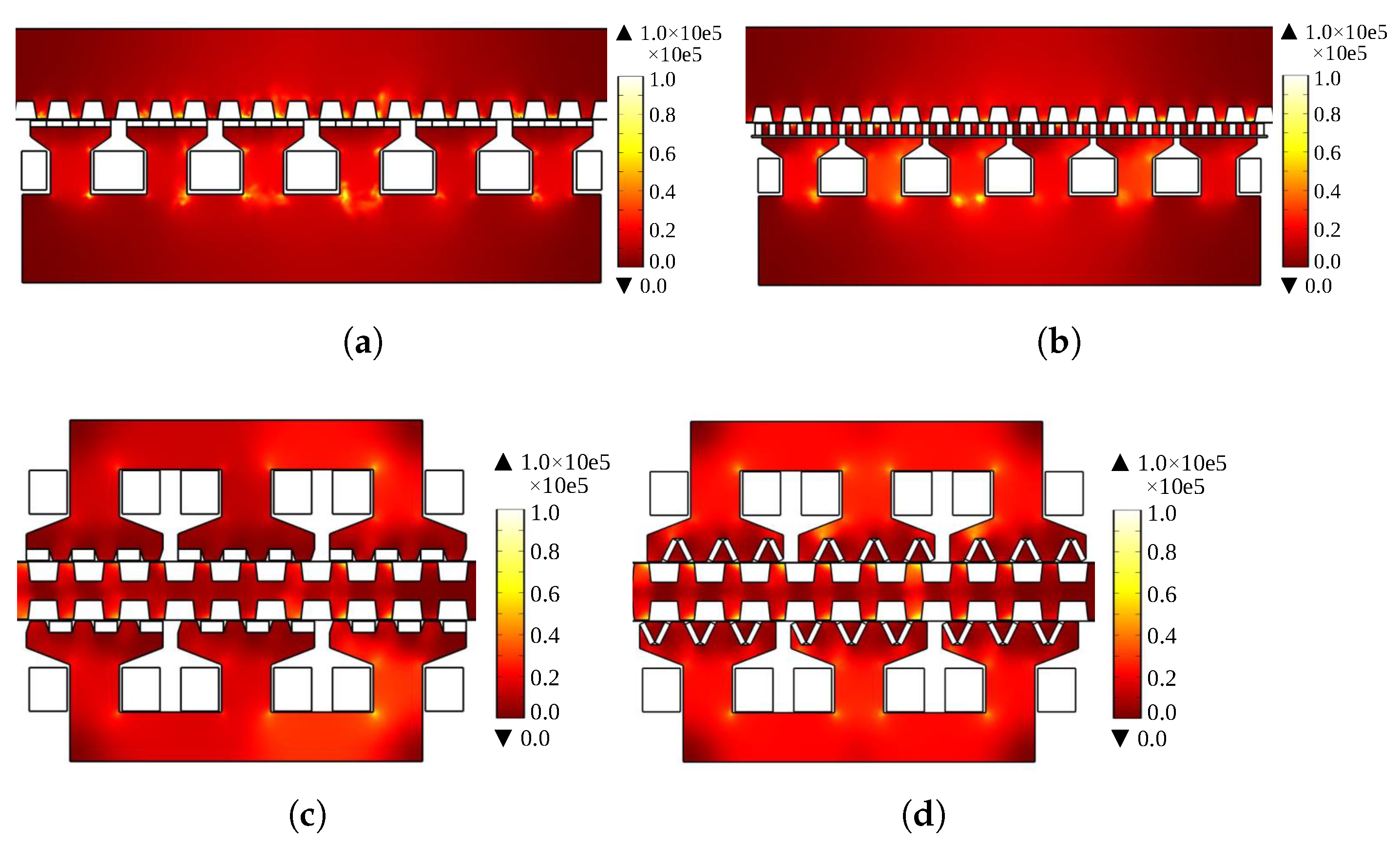
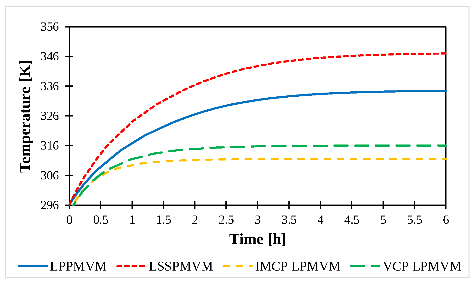
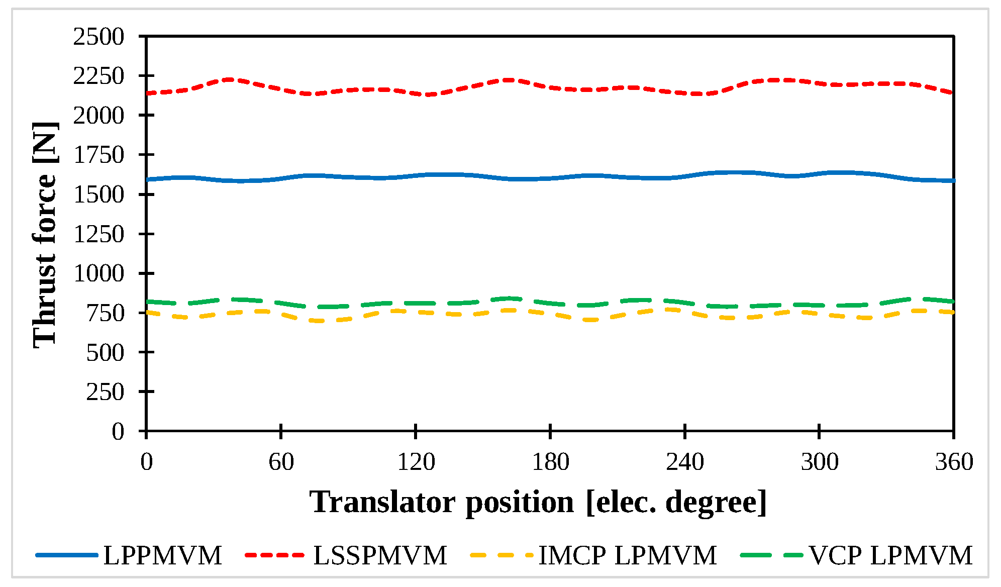
| LPPMVM [130] | LSSPMVM [132] | IMCP LPMVM [133] | VCP LPMVM [133] | |
|---|---|---|---|---|
| Structure | Flat | Flat | Flat | Flat |
| Single/double-sided | Single-sided | Single-sided | Double-sided | Double-sided |
| Armature winding type | Distributed | Distributed | Concentrated | Concentrated |
| PM type | Surface-mounted | Spoke-type | Consequent pole | V-type |
| Location of PMs | Stator | Stator | Stator | Stator |
| No. of PM pole pairs | 18 | 18 | 9 | 9 |
| No. of winding pole pairs | 1 | 1 | 1 | 1 |
| No. of translator teeth | 17 | 17 | 10 | 10 |
| Gear ratio | 17 | 17 | 10 | 10 |
| No. of PMs per stator tooth | 5 | 5 | 3 | 6 |
| Frequency [Hz] | 50 | 50 | 50 | 50 |
| No. of phases | 3 | 3 | 3 | 3 |
| PM volume [cm] | 120 | 150 | 64.8 | 64.8 |
| Magnet remanence [T] | 1.2 | 1.2 | 1.24 | 1.24 |
| Active length [mm] | 360 | 360 | 232 | 232 |
| Thickness of linear machine [mm] | 158 | 185 | 180 | 180 |
| Stack length [mm] | 100 | 100 | 50 | 50 |
| Translator tooth pitch [mm] | 21.17 | 21.17 | 24 | 24 |
| Stator tooth pitch [mm] | 60 | 60 | 80 | 80 |
| Airgap length [mm] | 1 | 1 | 1 | 1 |
| Rated speed [m/s] | 1 | 1 | 1.2 | 1.2 |
| No. of winding turns per phase | 142 | 140 | 90 | 90 |
| Current density [A/mm] | 4.3 | 4.3 | 3.5 | 3.5 |
| No-load back-EMF [V] | 60 | 87 | 45 | 57 |
| Flux linkage [Wb] | 0.19 | 0.30 | 0.14 | 0.18 |
| Average thrust force [kN] | 1.61 | 2.18 | 0.739 | 0.812 |
| Thrust force density [kN/m] | 283 | 327 | 354 | 389 |
| Force/PM volume [N/cm] | 13.4 | 14.5 | 11.1 | 12.5 |
| Power factor | 0.26 | 0.27 | 0.51 | 0.65 |
| Copper loss [W] | 243.5 | 240.1 | 62.6 | 62.6 |
| Core loss [W] | 44.4 | 61.5 | 18.4 | 22.0 |
| Efficiency [%] | 84.8 | 87.8 | 91.6 | 92.0 |
| Detent force pk2pk [N] | 31 (1.9%) | 36 (1.65%) | 59 (7.9%) | 48 (5.9 %) |
| Thrust force pk2pk [N] | 50 | 93 | 66 | 51 |
| Thrust force ripple [%] | 3.1 | 4.2 | 8.9 | 6.2 |
Publisher’s Note: MDPI stays neutral with regard to jurisdictional claims in published maps and institutional affiliations. |
© 2022 by the authors. Licensee MDPI, Basel, Switzerland. This article is an open access article distributed under the terms and conditions of the Creative Commons Attribution (CC BY) license (https://creativecommons.org/licenses/by/4.0/).
Share and Cite
Jafari, R.; Asef, P.; Ardebili, M.; Derakhshani, M.M. Linear Permanent Magnet Vernier Generators for Wave Energy Applications: Analysis, Challenges, and Opportunities. Sustainability 2022, 14, 10912. https://doi.org/10.3390/su141710912
Jafari R, Asef P, Ardebili M, Derakhshani MM. Linear Permanent Magnet Vernier Generators for Wave Energy Applications: Analysis, Challenges, and Opportunities. Sustainability. 2022; 14(17):10912. https://doi.org/10.3390/su141710912
Chicago/Turabian StyleJafari, Reza, Pedram Asef, Mohammad Ardebili, and Mohammad Mahdi Derakhshani. 2022. "Linear Permanent Magnet Vernier Generators for Wave Energy Applications: Analysis, Challenges, and Opportunities" Sustainability 14, no. 17: 10912. https://doi.org/10.3390/su141710912
APA StyleJafari, R., Asef, P., Ardebili, M., & Derakhshani, M. M. (2022). Linear Permanent Magnet Vernier Generators for Wave Energy Applications: Analysis, Challenges, and Opportunities. Sustainability, 14(17), 10912. https://doi.org/10.3390/su141710912