1. Introduction
Managing solid waste materials is among the most significant environmental concerns [
1,
2]. Non-hazardous solid waste is produced in the USA at a rate of five billion tons annually. Of these, each year the number of scrap tires generated is more than 290 million (approximately 3.6 million tons) [
3]. Municipalities all over the world face environmental challenges related to scrap-tire disposal. A variety of studies were conducted on reusing scrap tires in several products of plastic and rubber, incinerating them for electricity production, or using them as cement kilns fuel, as well as the manufacturing of asphalt concrete. The outline of some of the research concerning the use of Portland cement concrete containing scrap tires has been presented [
3]. Rubberized concrete mixtures made from scrap tires are workable [
4,
5,
6,
7,
8,
9,
10].
In most of the research, crumb rubber was used to partially replace coarse aggregate in concrete due to its environmental benefits [
11]. Concrete cylinders have been tested with different amounts of rubber and improved ductility was observed [
7]. Concrete specimens fabricated from rubber were found to have a lower brittleness index than concrete specimens fabricated from ordinary concrete, which indicates that rubber concrete exhibits better ductility [
7]. It was concluded that with compressive loads, rubber-concrete cylinders failed ductile rather than brittle, and they soak up a considerable quantity of plastic energy [
6].
Across all research conducted on rubber content in concrete, there was a reduction in compression strength and modulus of elasticity. Studies have shown that rubber-concrete can be used for nonstructural applications such as building facades, lightweight concrete walls, and architectural components, but not for structural purposes [
5]. Mixes of rubber and concrete can also be utilized for transportation purposes, including sound barriers, under flexible pavements, and crash barriers including cement aggregates [
6]. Similarly, it was recommended that a normal concrete’s aggregate proportions not exceed 20% rubber [
5]. Additionally, it was noted the compression strength of fine rubber crumbs was higher than coarse rubber crumbs [
5,
12,
13,
14].
For panels subjected to contact detonations, preliminary research indicated that rubberized concrete had improved blast resistance [
15]. An application of these observations such as the observed added ductility appeared in the concrete cylinders cyclic test [
7] and the ductile failure model of rubberized concrete cylinders led to this research in which the rubberized concrete panel performance under the far-field blast was tested. Therefore, this study compares rubberized concrete wall panels to normal concrete wall panels to determine the difference in blast performance.
One of the most significant wall system properties to resist blast loads along with mass is its ability to resist static loads. The static resistance function, i.e., the wall’s load-deflection response under uniform static pressure, is crucial for predicting the blast dynamic response and estimating the wall system energy absorption capacity [
16,
17]. In addition to providing insight into different failure modes, static resistance functions can also determine when a failure occurs [
18]. For design purposes, the static resistance function is increased by two factors. The first factor is the dynamic increase factor (DIF) which accounts for the strain rate effect [
19,
20,
21]. Design specifications define minimum mechanical properties for various grades of material. In practice, the average yield strength of steel materials being installed is approximately 25% greater than the specified minimum values. To account for this, the strength increase factor (SIF) can be used.
Several works recommend the use of crumb rubber in concrete as a sustainable alternative to conventional concrete in constructions. The objective of this paper is to investigate the static and blast performance of rubberized concrete walls. Under simulated uniform pressure, this paper measured the performance of full-scale concrete walls with a simply supported span of 3.05 m loaded at 16 points along the span. The concrete walls were partially replaced with coarse aggregate with varying rubber contents. For each rubber content of the concrete walls, three cylinders were cast into 204 mm × 102 mm molds and cured for 28 days. Compressive strength, rupture modulus, and splitting tensile strength were performed. These results allowed the development of the static resistance functions and the determination of failure modes. With the addition of rubber to the walls, the walls have a reduced static resistance as well as mass.
2. Static Resistance Function
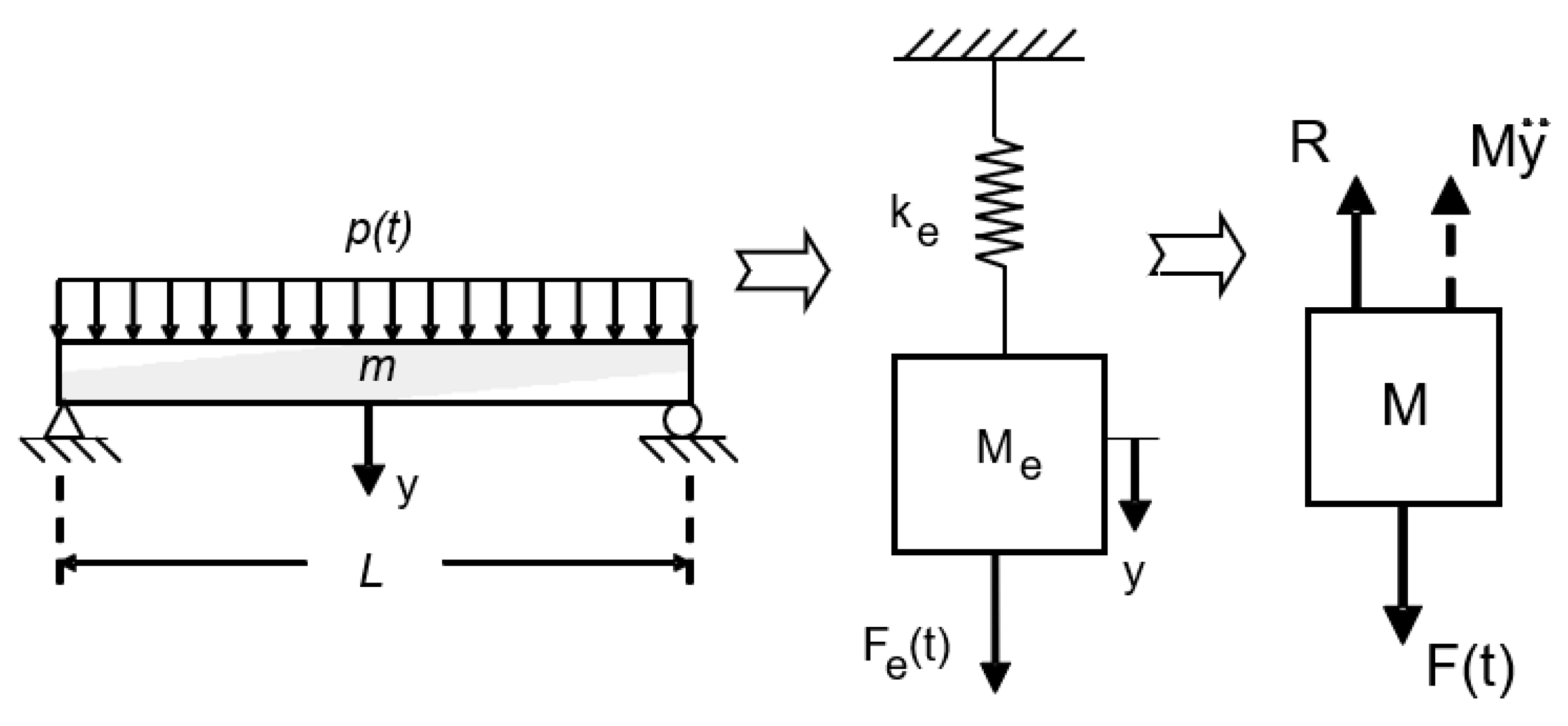
Structural response to blast loads is predicted with dynamic models used in blast design. By combining springs and masses, structures can be idealized and represented by proper mass and load factors. This simple spring-mass system can be used to model the behavior of a beam or the effects of a wall, for example, subject to uniform dynamic pressure, as shown in
Figure 1.
A realistic representation of the actual structure is necessary for accurate modeling. Therefore, proper system parameters need to be chosen, which include the spring constant ke and the mass Me. By looking at the properties of the wall or beam we can find the spring constant ke, simply called the resistance of the system. It is normal that a static resistance function, R, is utilized for complex systems where the force-displacement relationship cannot be defined by a single ke. As a result of choosing an equivalent system, the deflection, y, of the concentrated mass will match some substantial point of the structure, as the middle span of a beam. Evaluating these constants of an equivalent system is based on assuming that the structure would be deformed if dynamic loads were applied statically.
When converting a real system to an equivalent system, it is convenient to introduce some transformation factors. The equivalent one-degree parameters are determined by multiplying the real structure’s total load, mass, and resistance by the corresponding transformation factors. Furthermore, dynamic load factor (DLF) is used to modify the static resistance to reflect strain rate effects. Biggs (1964) provides detailed information on this procedure [
22].
It is uncertain how a structure will react to a blast. Loads generally follow the path of least resistance when they are applied to a structure. A building envelope may suffer permanent deflections due to pressures placed on it by an explosion. In order to predict a wall system’s behavior easily, the inward movement is simplified in the modeling process. Simulated dynamic models with a single degree of freedom (SDOF) are commonly used. The model described in Biggs (1964) supports only one type of motion in any instant, i.e., one coordinate system can describe the motion of the system at each instant [
22].
The mass of the system shown in
Figure 1 will only be able to move upward in the vertical direction due to the system is assumed to be an SDOF system. Dynamic modeling begins with constructing a free-body diagram by isolating a mass (
Figure 1) and then applying the concept of dynamic equilibrium to write an equation of motion. The system equation of motion, shown in
Figure 1, can be represented as follows:
During this process, Mÿ represents the inertia force and R represents the spring resistance force. F(t) represents the externally applied force, y represents displacement, and ÿ represents acceleration. As soon as the specific parameters are defined, it can be solved to evaluate the variations in deformation with time. Thus, for a structure or structural element to perform dynamically, it is necessary to know its static resistance. To conduct this study, rubber-concrete wall specimens, RCON, were tested experimentally for Static Resistance Function.
3. Experimental Setup and Procedure
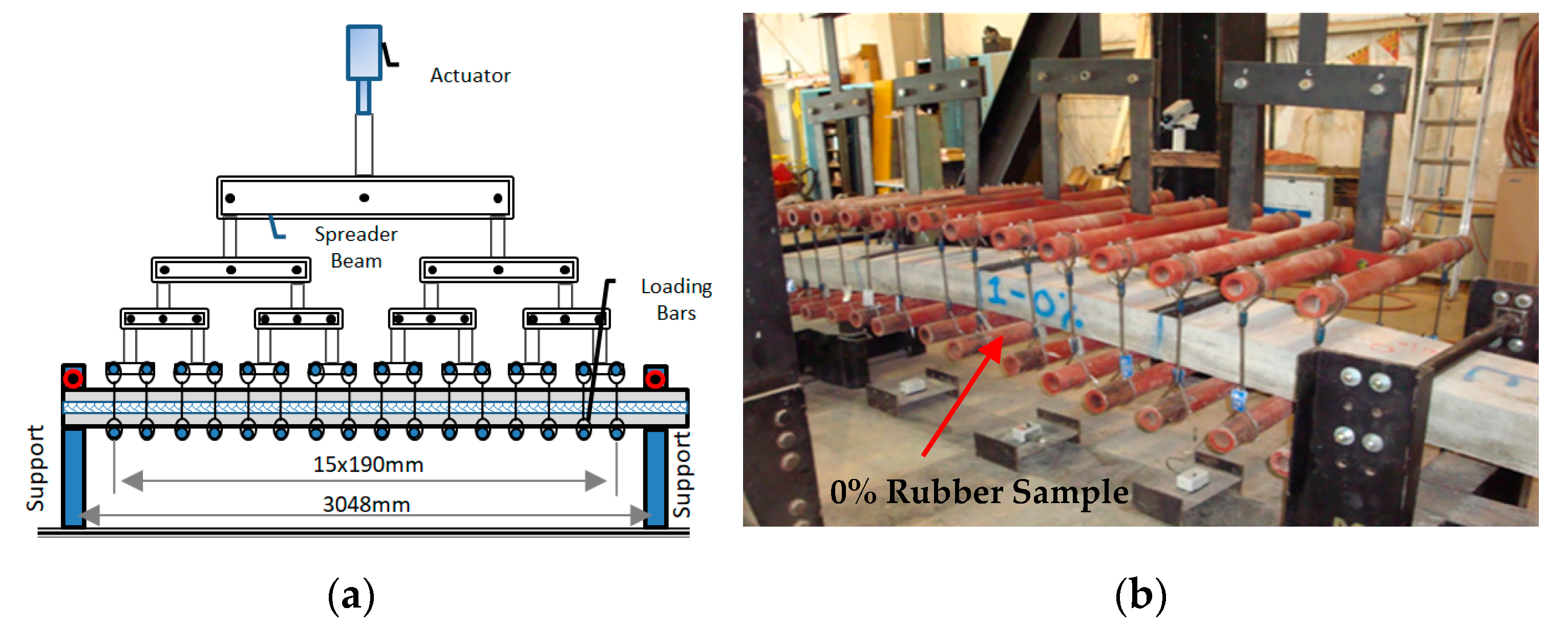
A load tree was used to simulate the uniform loading of specimens. A simply supported span of 3.05 m (120 inches) was loaded at 16 points along the span,
Figure 2a. The applied load was measured by using a load cell and displacements along with the specimen at quarter points were measured by using a displacement gage. In
Figure 2b, the load-deflection response of the specimens was used to develop the static resistance functions after failure.
The specimen was connected to three string potentiometers at the quarter points to measure displacement. The specimens were covered with rubber mats at these points and the chains were wrapped around them. String potentiometers were mounted on the chain at each location with connecting strings. Testing was recorded by cameras. During the testing, one camera was positioned in the middle of the specimen, where the failure of the specimen should be expected, while the other camera was positioned at the end of the specimen, where deformation of the specimen could be seen during testing.
The Air Force Research Laboratory at Tyndall, FL, has cast test specimens with various rubber contents that partially replaces the coarse aggregate in the concrete mix. A total of nine wall test full-scale specimens were made, with three specimens of each variation in coarse aggregate replacement.
Table 1 shows the test matrix for the normal concrete by using three rubber contents 0, 20, and 40% of the used coarse aggregate content by volume.
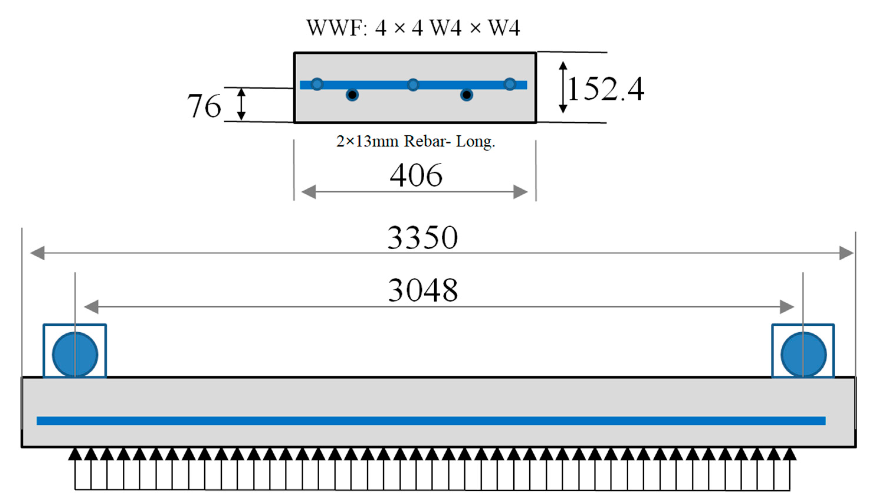
A similar reinforcement and dimension were used on all specimens. A cross-section of all specimens had a width of 406 mm (16 in) and a depth of 152 mm (6 in), with a span of 3.66 m (144 in). In
Figure 3, the reinforcement consists of welded wired mesh fabric (WWF) 152 × 152 W13M/W13M (4 × 4 W4/W4) laid over two reinforcement bars 13M (#4) A706 at a depth of 76 mm (3 inches) from the tension face.
In their original cast frames, the test specimens were shipped from AFRL to the University of Missouri Remote Test Facility (RTF) at Columbia, MO. Two specimens on the bottom cracked due to stacking of the samples during shipping. A crack developed on RCON 1 at a distance of 2.13 m (84 in) from one end, and on RCON 7 at a distance of 1.7 m (67 in) and 1.98 m (78 in) from one end.
During working in the RTF, all specimens were labeled, and the wooden forms were removed. Specimens were placed on carts and pushed into place between supports beneath the loading tree. A series of 16 load points across the span was created by connecting steel bars to the tree below the specimen. After raising the specimens, the carts were removed, and the specimens were supported by supports.
Cameras were used to examine the specimens after the string potentiometers were attached. During the test, notes and pictures were collected. In general, the specimens were tested to a maximum deflection of 635 mm (25 in), unless the instrumentation failed. The crack measurement was performed after testing was terminated.
4. Experimental Evaluation
As part of the experimental study, the researchers of [
15] assessed the material properties and compressive strength of each concrete mix. A full-scale load tree simulating uniform static pressure was used to determine the static resistance function of the specimens. Furthermore, measurements were taken of the rebar depths and unit weights on the failed specimens as well as cracking patterns.
4.1. Rubber Aggregate
Shredded scrap tires were used to produce the crumb rubber aggregate. Metals and dust were mostly removed from the scrap tires. The specimens used in the research included fibers from the tires. Crumb rubber can be produced by several methods including cryogenic, ambient, or wet grinding. The cryogenic method requires the tire to be frozen prior to the shredding process. This eases the shredding process but alters the mechanical characteristics of the rubber. Ambient techniques allow for tires to be shredded at room temperature. This method does not alter the mechanical properties of the rubber and was chosen for the research study. Coarse and fine rubber aggregate was used in the research. The ambient crumb rubber is available in various gradations; a #5 gradation (6.4–9.5 mm; 545 kg/m3) was used in this study for the coarse aggregate replacement.
4.2. Mix Design and Concrete Cylinders
In accordance with ACI 318, the mix of the normal concrete was designed. Traditional materials were used for the concrete mixture design. Type I cement crushed coarse mineral aggregates, natural fine mineral aggregates, and crumb rubber was used. Crushed limestone was used for coarse aggregate. A #67 coarse aggregate gradation (0.75 into No.4) was used and natural sand was used for the fine aggregate. A standard concrete sand gradation was used in accordance with [
23]. A water-cement ratio of 0.40 was used.
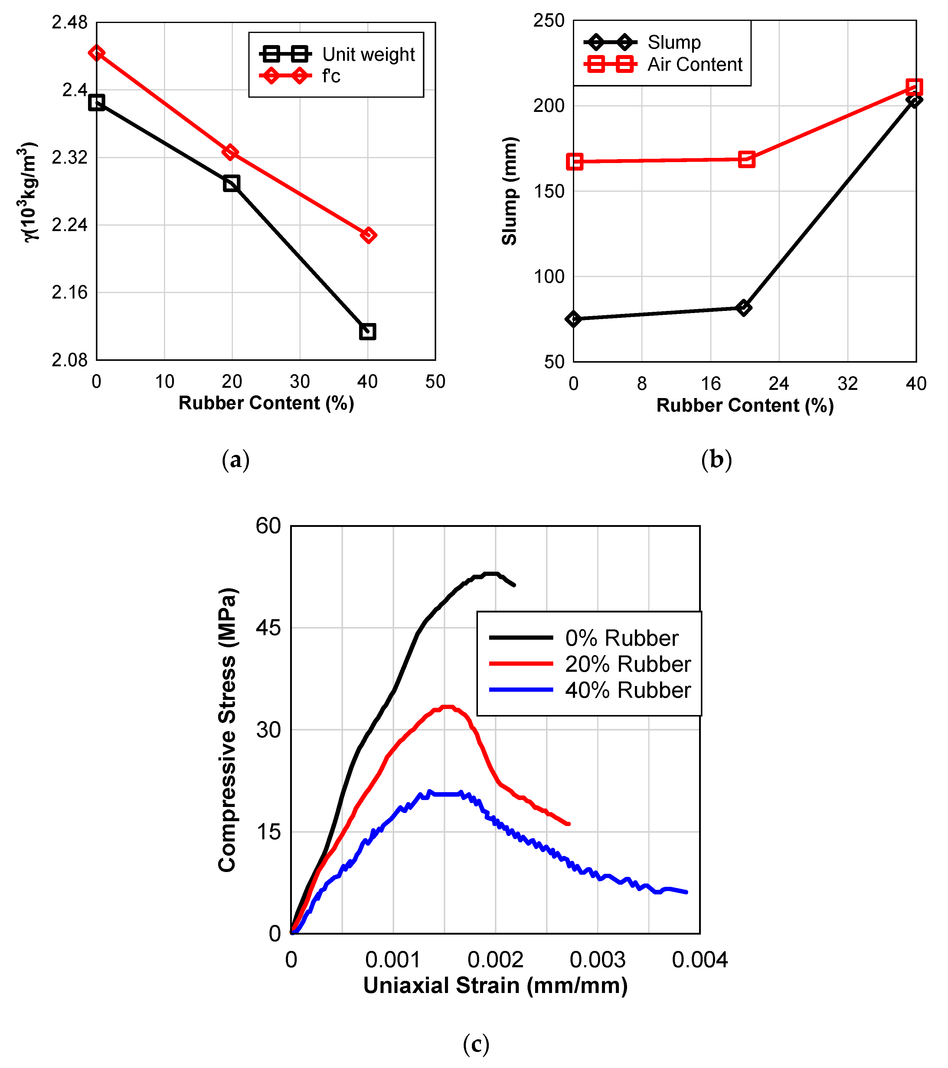
Table 2 shows the properties of concrete mix for different contents of rubber in addition to
Figure 4a–c.
For each rubber content of the concrete cylinders, three cylinders were cast by pouring them into 204 mm × 102 mm (8 inches × 4 inches) molds and allowing them to cure for 28 days according to the specification [
24].
Table 3 shows the results of compressive strength, rupture modulus, and splitting tensile strength tests performed [
25,
26,
27].
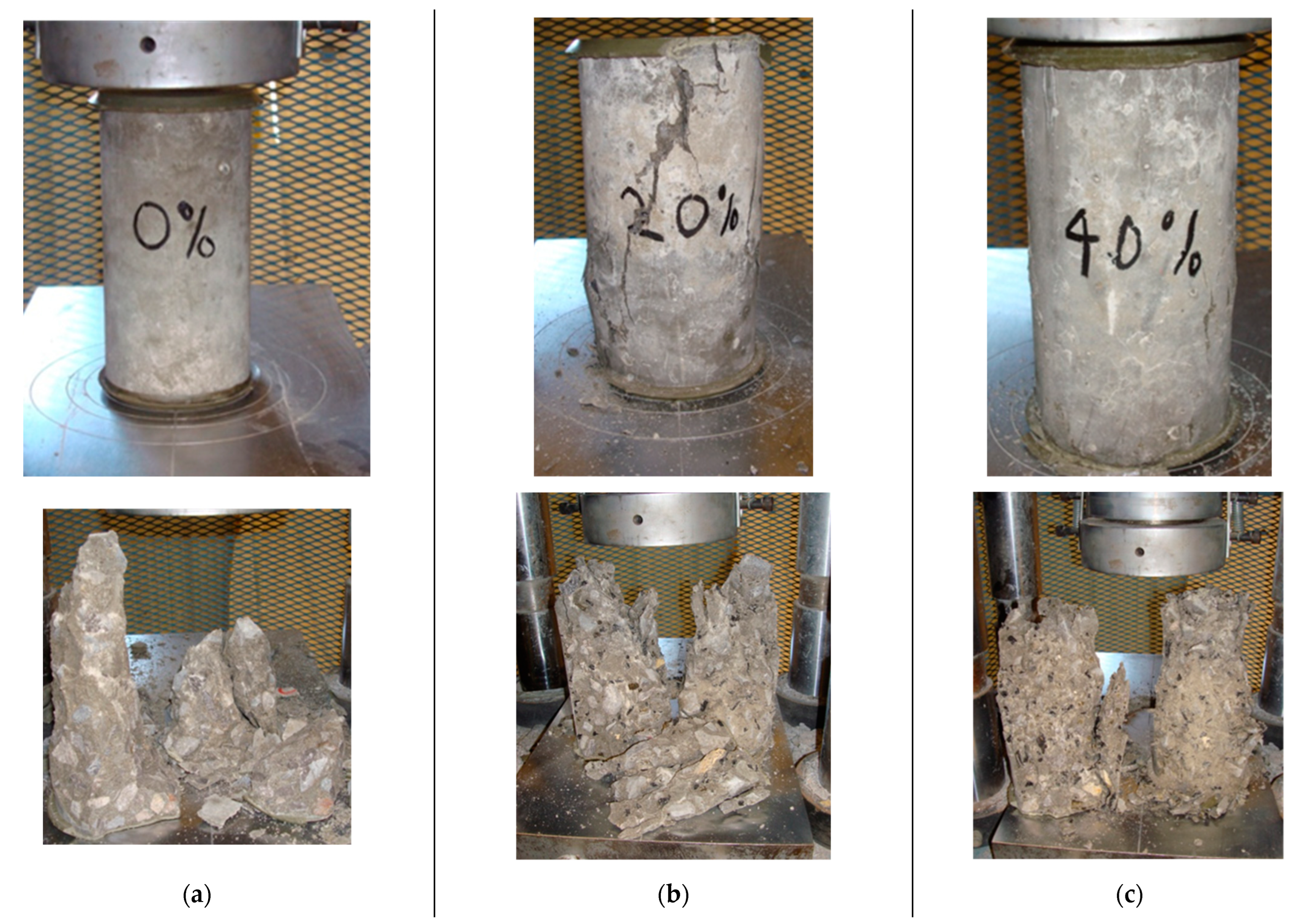
The cylinder test failure modes are shown in
Figure 5a–c. The splitting-tensile and compressive strengths for the RCON cylinders demonstrated lower than the normal concrete samples. Despite this, RCON samples have not shown brittle failure, but rather plastic, ductile failure, and multiple fractured surfaces when subjected to ultimate loads.
Figure 5 presents the uniaxial compression response of the cylinders as well as the results of cylinder testing.
4.3. Load Tree Testing
Five to eight cracks developed at quarter points and one to three elsewhere on control specimens RCON 1–3 that had 0% rubber content. First, the welded wired mesh failed followed by the crushing failure in samples RCON 2 and 3; on the other hand, the compression failure in RCON 1 occurred during the formation of a four-hinge mechanism near the midspan between two cracks. Following this, a hinge location was developed by the welded wired mesh, resulting in a three-hinge design. Near the failure cross-section of all RCON 0% specimens, longitudinal cracking and further compression failure were evident, suggesting them to have slipped in depth. The rebar on one side of RCON 3 failed at the middle hinge. RCON 3 was terminated when the midspan deflection reached 381 mm (15 in) of the string potentiometer, however, the other tests were terminated when midspan deflection reached 635 mm (25 in).
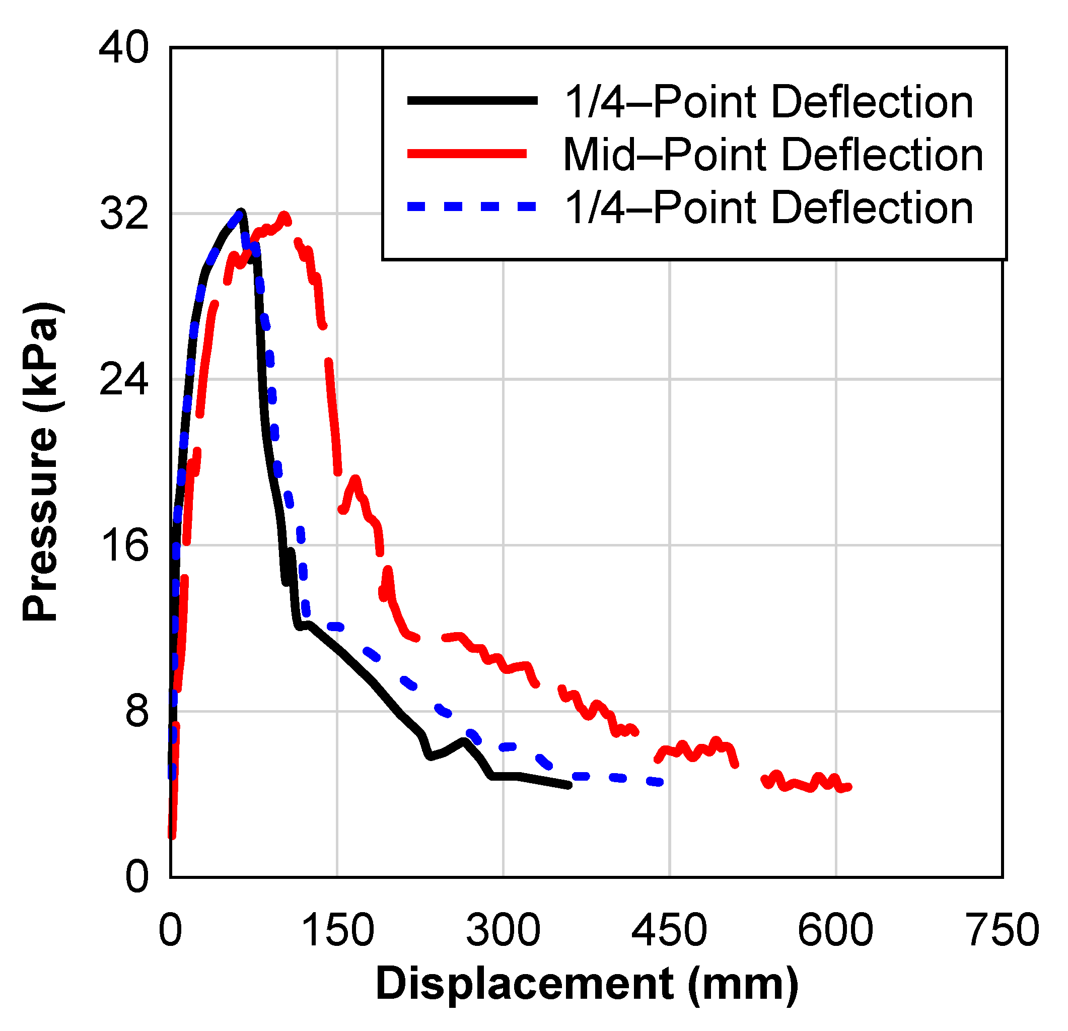
Figure 6 shows the response of the RCON 1–3 specimens to pressure deflection. The responses were generally linear until the concrete cracked, followed by a region of plastic nonlinearity until failure. As a result, the resistance abruptly dropped followed by a flattened plastic deformation zone up to the point where the concrete failed in the compression region. Moreover, the rebars slipped away from the compression face as longitudinal cracks developed, eventually resulting in a gradual drop in resistance.
Figure 6 shows a typical 0% RCON specimen’s midspan and both ¼-point deflections, and the static resistance of the three 0% RCON specimens can be seen in
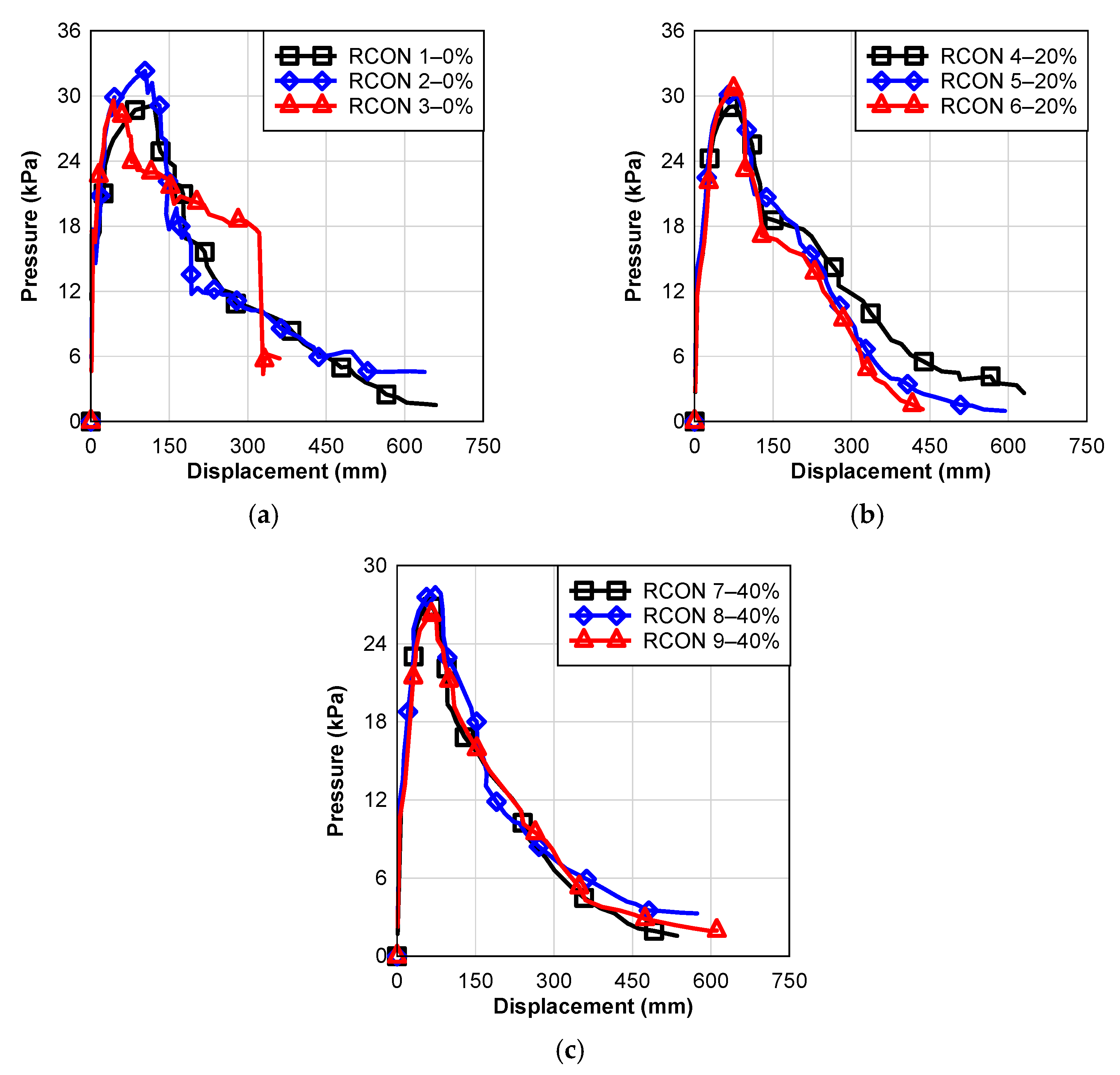
Figure 7a.
When subjected to uniform loading, specimens RCON 4–6 containing 20% rubber exhibited similar behavior. Approximately eight to nine cracks formed in quarter locations and two cracks formed through pick locations shortly after the test started where the spreader was attached. Additionally, at the outside quarter-point cracks developed through each RCON 5 and 6. The three-hinged mechanism was created by compression failure near midspan, followed by a failure at the welded wired mesh at the hinge point. A compression failure and longitudinal cracks were observed near the hinge. In all cases, testing was terminated when the minimum load was achieved and a disconnection happened at the string potentiometer at the midspan at a value close to 635 mm (25 in) of deflection, except RCON 6.
Figure 7b shows the pressure-deflection behavior of the RCON 4–6 specimens. Concrete generally responded linearly until it cracked, followed by a bilinear plastic region until the compressive side of the concrete wall failed. Consequently, this caused the resistance to gradually drop and then suddenly fall due to the failure of the welded wired mesh. Once longitudinal cracks developed, the resistance decreased gradually until the rebars slipped towards the compression face, eventually causing the test to fail.
RCON 7–9 containing rubber 40% typically performed similarly to specimens that contained 20% rubber. Within quarter points, 8 to 10 cracks developed, and two cracks penetrated pick locations. RCON 7 was the only exception, which developed three cracks outside of quarter points, and just only one of them come across a pick point. The specimens were deformed into three hinge mechanisms by a compression failure close to midspan. In addition to longitudinal cracks near the failure locations observed along with additional compression failures, welded wired mesh was also found to fail at hinge locations. The RCON 7 sample showed a failure cross-section adjacent to the existing shipping crack. For RCON 7, the test was stopped due to minimal load, as well as for the RCON 8 sample at 635 mm (25 in), and for the RCON 9 sample when the string pot at midspan had reached its maximum travel of approximately 610 mm (24 in).
Figure 7c illustrates the pressure-deflection relation of the RCON 7–9 specimens. Overall, a linear response was observed until the concrete cracked, then a region of softer linear plastic occurred until the compressive concrete face had a crushing failure. Due to the failure of the welded wired mesh, the resistance significantly decreased followed by a sudden drop to a value of about zero. Over time, the resistance decreased during the longitudinal crack allowing the rebars to slide in the direction of the compression side, resulting in the test being ended.
4.4. Rebar Depths
To determine the reinforcement depth, specimens were cut at two places after testing. In all cases, the depth was measured from the specimen tension face to the midpoint of the rebar. As shown in
Table 4, the rebar depths of the slabs were measured from their tension faces.
4.5. Unit Weight
The RCON specimens were cut into blocks and weighed dry and submerged after testing. In some places where there was no reinforcement, the specimen was cut a few inches in from the edge. For the RCON specimens, calculated unit weight and average weight measurements are given in
Table 5. As hypothesized and as determined based on the cylinder measurements (
Table 2), an increased percentage of rubber replacement corresponds to a decrease in unit weight. It seems that the unit weights of the cylinders after testing were generally decreased, as shown in
Table 5.
5. Load Tree Test Observations
On all specimens tested, the cross-sectional failure occurred near the midspan where a transverse welded wired mesh was installed. Welded wired mesh and concrete compression failure resulted in longitudinal cracking close to failure. Except for the control specimen RCON3, none of the main reinforcement bars failed. Moreover, shear cracks in the diagonal direction were not found in any of the specimens; all cracks were flexural in nature.
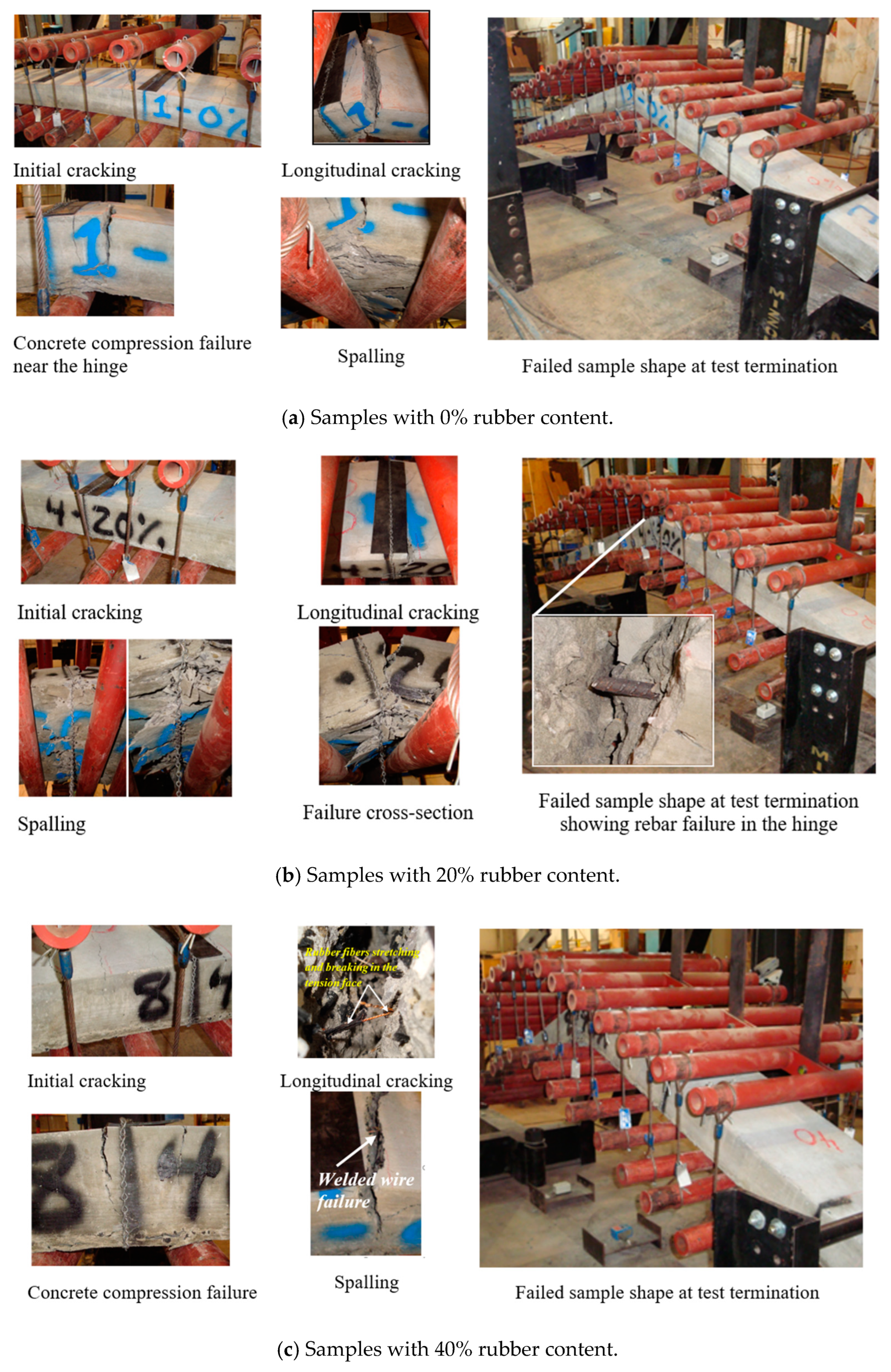
For the control specimens,
Figure 8a shows a variety of failure modes that are usually observed for various stages of resistance. The span first cracked near the midpoint, followed by more cracks throughout the span’s ¼-points. Near midspan, compression failure of the concrete was followed by hinge development which led to spalling in the compression zone of the concrete. During catenary action developed in the rebar, longitudinal cracks started to form near the failure cross-section location as the steel rebar slid towards the compression side. Three-hinge mechanisms were typical failure shapes at test termination.
Figure 8b,c illustrates the response of 20% and 40% rubber contents for RCON specimens. Near the midspan, initial cracking was noticed followed by additional cracking in the span’s ¼-points. As compared with the control specimens, the RCON specimens showed more tension cracks. However, as a result of rubber fibers provided in specimens, the spalling was less severe in these specimens than in the control specimens. Afterward, the welded wired mesh failed at midspan and then developed longitudinal cracks.
In
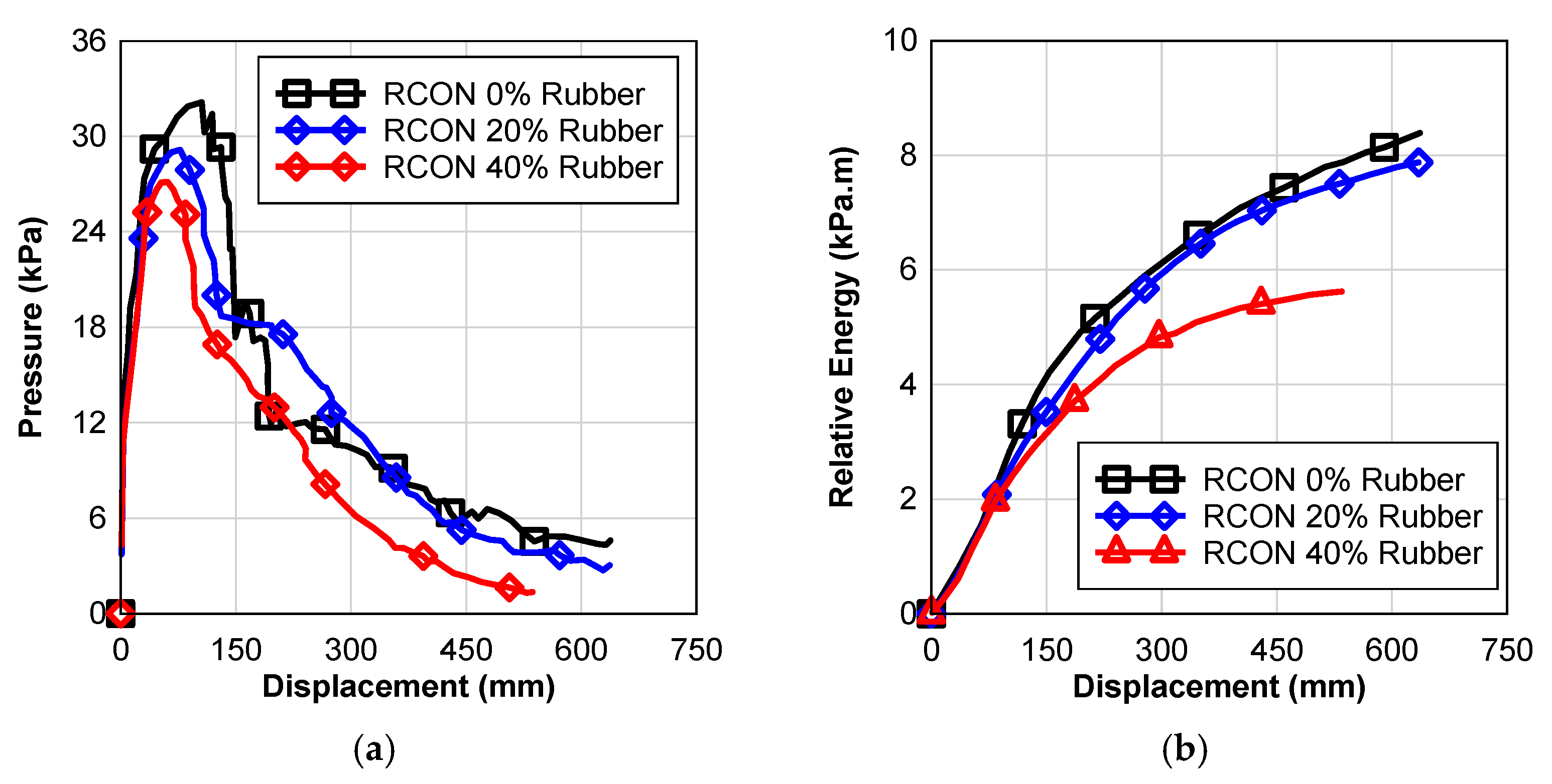
Figure 9a, it can be noticed that with increasing rubber content, the resistance decreased for the RCON specimens. A lower modulus of the RCON specimens may have contributed to more cracking on specimens with higher rubber content. Furthermore, the energy-absorption potential of rubber is lower with increasing rubber content (
Figure 9b).
As shown in
Figure 9a, the RCON specimens tested had an average static resistance. Before the first crack, stiffness decreased with increasing rubber content, on the other hand, after the first crack as rubber content increased it increased the stiffness (
Table 6). As shown in
Table 6, the compression strength of the specimens decreased with increased rubber content, explaining the decrease in stiffness before the first crack. As shown in
Figure 9a and
Table 6, the bridging of rubber fibers/shreds across the cracks and the resulting delay in crack formation can be attributed to the increased stiffness after the first cracks. Rubber content reduced RCON specimens’ overall resistance and ultimate capacity
Table 6.
In specimens with rubber, there was less spalling of the compression face compared to control specimens, while for RCON specimens with rubber, welded wired mesh failure occurred before compression failure. It is common to see compression failure before welded wired mesh failure in the control specimens. Compared to the control specimens, the specimens with rubber showed more transverse cracks throughout the span. Concrete stress in the compression zone could have been reduced by this. Furthermore,
Table 6 shows that RCON specimens with rubber had a lower compressive strength than the control ones. RCON specimens 4–9 experienced their first failure of compression concrete face due to this condition.
6. Blast Response Comparison
The average static resistance functions developed in this paper were used to predict the dynamic response of the RCON walls. Using external explosions as inputs, the equation of motion was solved to obtain analytical response predictions. The static resistance functions found in
Figure 7 were used to solve the equation of motion. The objective of this section is to compare the different blast responses with different contents of rubber, therefore, DIF and SIF were set to one in this study [
20,
21,
22].
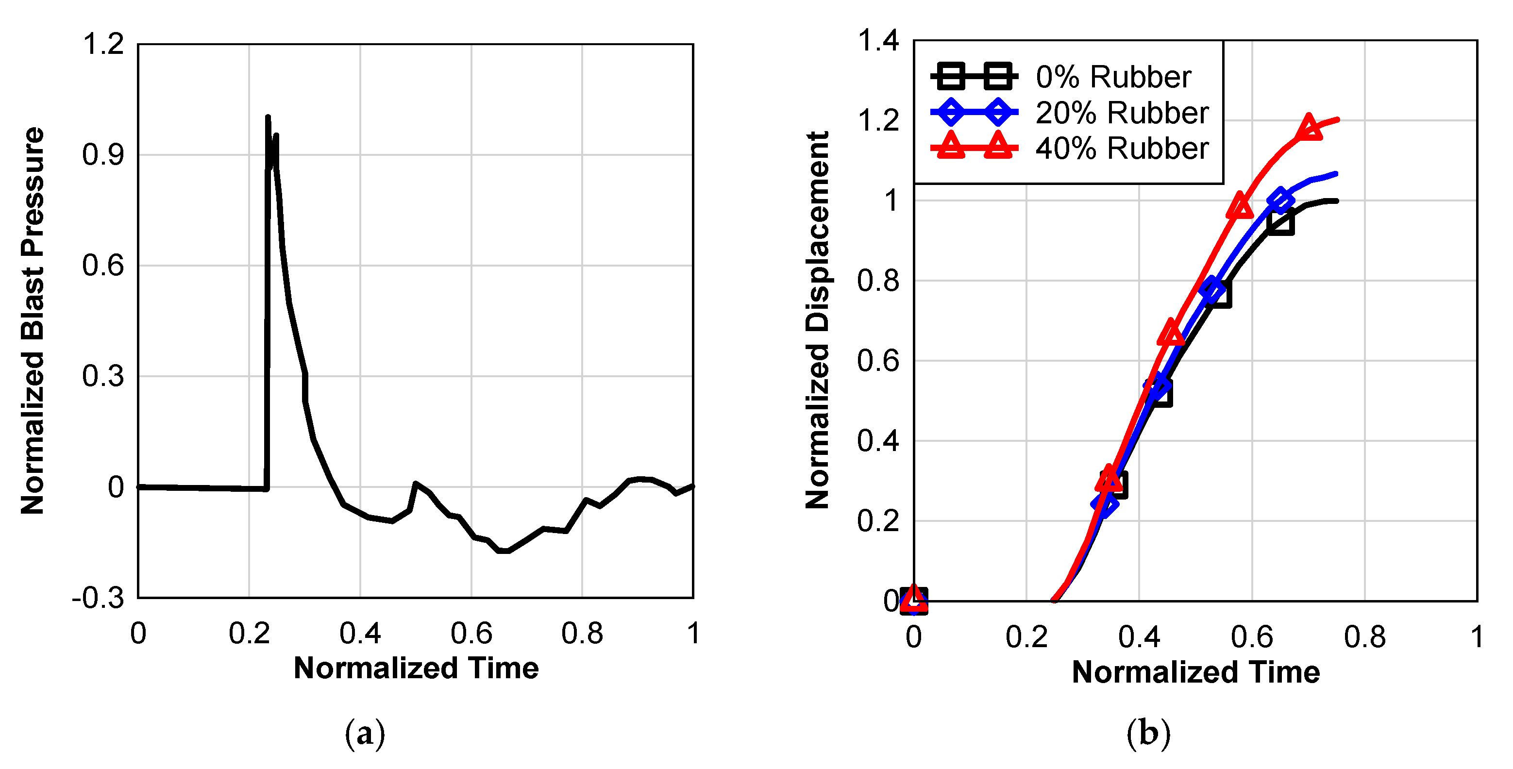
Figure 10a shows the normalized time series of reflected blast pressures after a far-field explosion, which loads the wall; the actual number of explosions has not been released but can be obtained from AFRL.
Using the SDOF procedure of Equation (1) with resistance functions in
Figure 7 and loading history in
Figure 10a, the dynamic response to the blast was calculated for three walls that contain 0%, 20%, and 40% rubber, as illustrated in
Figure 10b. Rubber’s addition to partially replacing coarse aggregate reduced the blast resistance of the walls as predicted normalized deflection increased. Since the blast resistance of the walls was reduced, the rubber content instead of coarse aggregate was added. As a result of the addition of rubber to the walls, the walls have a reduced static resistance as well as mass.
7. Conclusions
Managing solid waste materials is among the most significant environmental concerns. Non-hazardous solid waste is produced in the USA at a rate of five billion tons annually. The use of shredded rubber in the concrete mix in place of coarse aggregates can be considered a sustainable solution for these unrecyclable materials. A wall system that was constructed with shredded rubber in the concrete mix in place of coarse aggregates in a typical concrete mix was tested for static resistance. In comparison to normal concrete without any rubber replacement, rubber concrete showed lower compressive strength and modulus. Rubber was added to replace coarse aggregates in the concrete, to reduce the overall static resistance of the wall specimens. A reduction in wall mass and resistance caused the walls with rubber to be less blast resistant. Likewise, the failure mode for rubberized concrete specimens differed from that for concrete without rubber. After the first crack emerged in the specimen until ultimate, the rubber specimens had larger stiffness and more cracks along the span length. Based on the results of this study, concrete walls with rubber replacements for coarse aggregates do not improve blast resistance in far fields, while affecting it negatively when compared with normal concrete. In addition to the existing testing, additional tests should be carried out to investigate the effect of significant parameters that might affect blast resistance; for example, the size and shape of rubber shards and the use of fine rubber in concrete to replace the fine aggregate.
