1. Introduction
The desire to “Go Green”due to worries about the shrinking non-renewable energy sources and the preservation of the environment has substantially increased the use of renewable energy sources (RES) for electric power generation. In addition, to be in line with United Nations Sustainable Development Goal (SDG) and ensure access to affordable, reliable, sustainable, and modern energy for all, the use of RES is increasing [
1]. In this regard, most countries have set a target to achieve a renewable energy mix in their total generation by 2030, which has resulted in an increase in the level of distributed generation (DG). For instance, Malaysia has given the regulations to realize a 31% objective from the entire share of energy from RES [
2] by 2025. DG has been the impetus in the transformation of the traditional distribution scheme to a much more green, sustainable, flexible, reliable, and efficient power distribution scheme known as distributed system (DS). The introduction of DS into the power system helps to promote the usage of RES. Furthermore, power losses in the system could be reduced with power generation closer to the load points. Moreover, DS can reduce peak power generation from the centralized coal-fired power plant. Thus, reducing the emission of greenhouse gases.
Nevertheless, DS has many issues that need to be addressed pertaining to their voltage and frequency standard [
3], especially during islanding. For DS to be independent of the main grid, it needs to solve the lack of power inertia problem in its power system [
4]. The main sources of power generation in a DS come from solar power, small wind turbines, a battery energy storage system, and mini hydro power, all of which have little to no inertia reserve. During islanding, DS based on RES could not react to any sudden changes during the inertial period of frequency responses. DS-based RESs are connected to the power system via a power converter that does not offer inertia support like a conventional synchronous generator (SG). Even the process of (sudden) islanding for a low inertia DS would cause spikes in frequency and risk damaging critical equipment in the DSs. One way to maintain the stability of the DS is to introduce ancillary service that can inject artificial inertia into the network.
A few solutions were introduced to mitigate low inertia power systems, namely virtual synchronous generator (VSG). VSG is a concept that modeled a cylindrical-rotor-type SG architecture. It was first proposed in the European project “VSYNC” [
3]. The swing equation in SG is used to calculate the VSG inertial response. In an SG, these parameters are determined by the rotational kinetic energy stored in the rotor at a certain rated speed. These parameters cannot be changed unless one changes the physical component of the rotor. However, in a VSG controller, these parameters are not constrained to any physical limitation. Therefore, they can be adjusted in real-time to improve and optimize the controller performance. A variety of VSG controller methods have been reviewed, ranging from conventional to intelligence techniques [
5]. Initially, VSG used a droop controller to regulate the inertia response [
6]. An improved droop controller was introduced, which helped to reduce the frequency nadir, but the droop controller alone could not solve the oscillation problem that occurs after each VSG injection.
Alternating methods were proposed to improve the dynamic performance of VSG inertial response. Large inertia is needed to overcome the high rate of change of frequency (ROCOF), while low inertia is needed to subdue the oscillation. By adjusting the key parameters in the VSG controller, the oscillation problem is reduced. Thus, VSG with an alternating moment of inertia was introduced to compensate for the problem from the droop controller by damping the power oscillation after each VSG response. However, the proposed technique switched between small and big virtual inertia value [
7], which limit the range of the VSG inertia support. Another concept to mitigate the power oscillation problem is by alternating the damping constant of the VSG controller. However, it does not reduce the frequency of nadir during high ROCOF [
8]. The time for the frequency to recover to its nominal frequency is too long. Although it helps reduce the oscillation, it takes a longer time to stabilize and return to nominal frequency. Consequently, the addition of a fuzzy inference system (FIS) in the VSG controller was proposed to regulate the alternating value of inertia. A variety of FIS techniques have been used to improve the VSG concept. FIS in [
9] regulated the VSG output only from the ROCOF value. With a fixed range of membership functions (MF), the FIS proposed was unable to cover a wide range of over- and under-frequency events. In [
10], optimization of FIS was applied to regulate only the oscillation of VSG injection. In contrast, FIS in [
11] was used to generate active and reactive power references for VSG according to the DS connection mode. However, the FIS design had too many inputs and the input MF were not optimized, resulting limited VSG range response.
There is no work being carried out to optimize the membership function of a fuzzy inference system (FIS) for the active power controller in VSG. Either the input MF or the output MF. By optimizing both the input and output MF, a wide range of responses and input scenarios could be managed in real-time by scheduling through FIS. FIS will optimize and update the MF whenever the system responses are out of the safe operating region. Instead of continuous MF optimization, most controllers change the values of J and D in a linear or flip-flop manner.
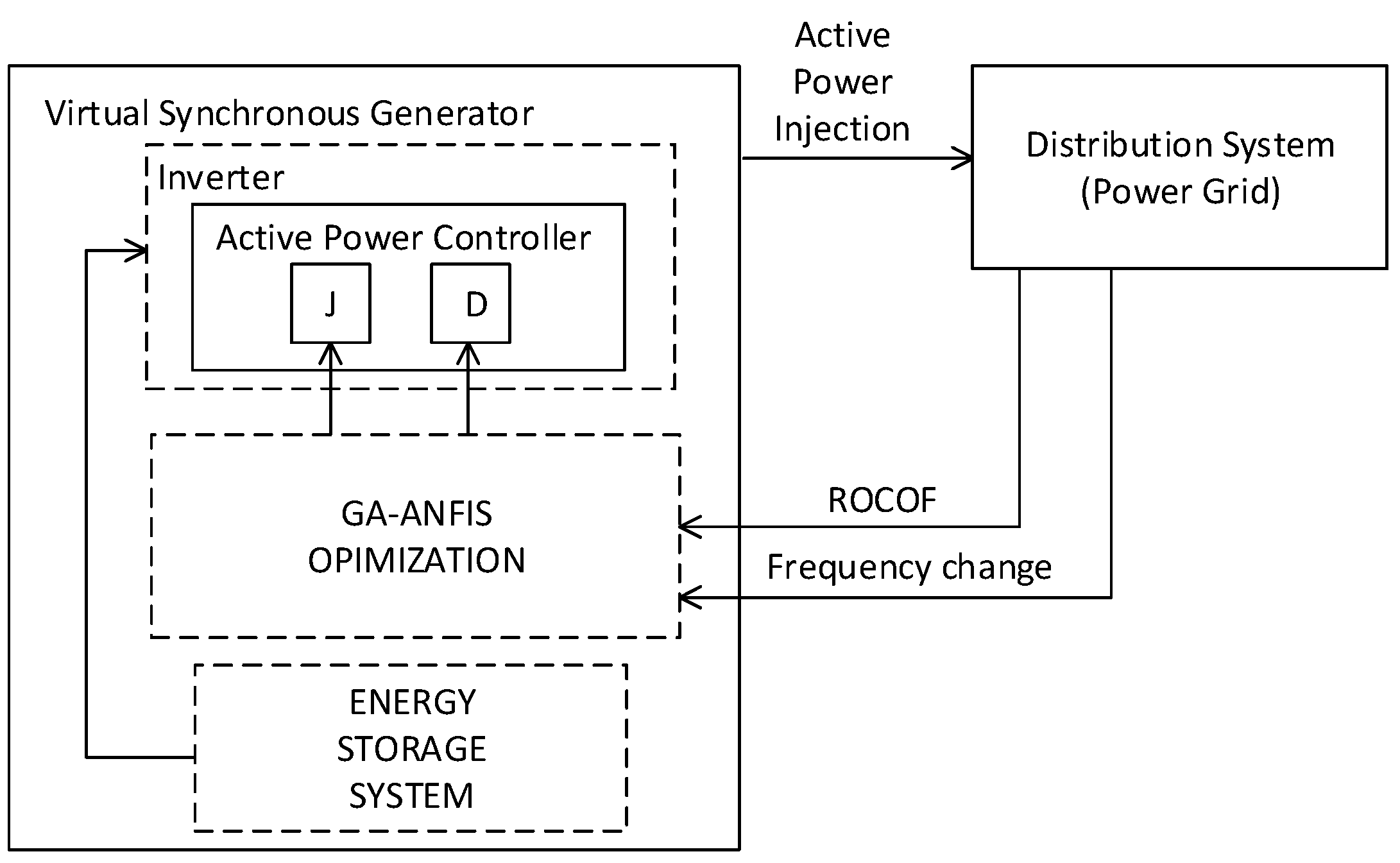
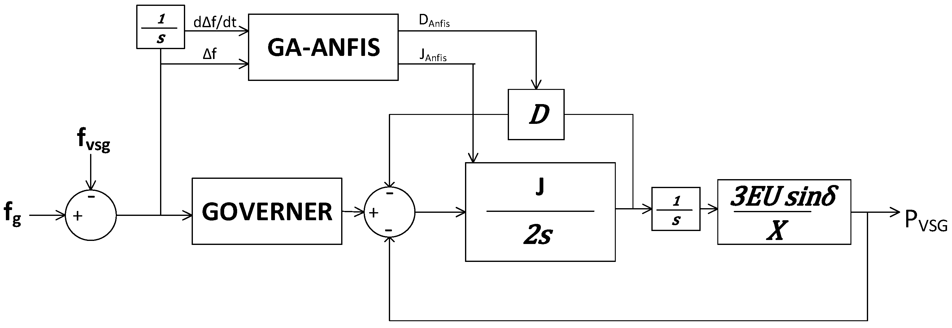
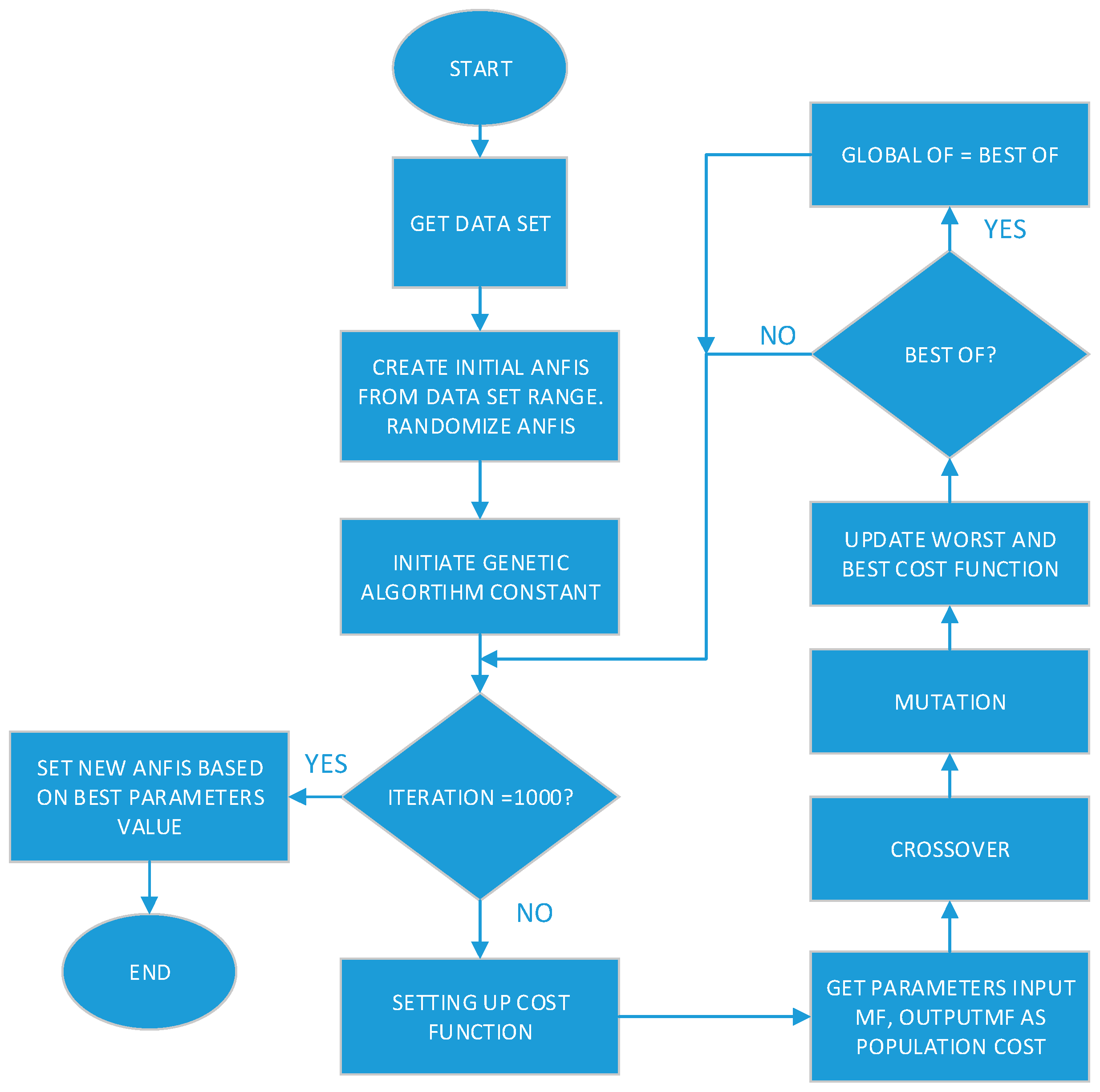
Considering the limitations of the previous VSG controllers, this paper proposes a new controller, which incorporates a genetic algorithm (GA) optimized adaptive network-based fuzzy inference system (ANFIS) to improve the performance of the active power controller in VSG. Two parameters of VSG’s swing equation, namely inertia constant, J, and damping constant, D, are optimized to give a wide range of VSG responses. The input parameters for ANFIS are the rate of change of frequency (ROCOF) and the change in frequency. While the output parameters for ANFIS are inertia constant, J, and damping constant, D. Membership function (MF) used for both the input and output are gauss MF. GA is used to optimize the MF for both the input and output of ANFIS. As a result, both input and output MF are heuristically designed to manage a wide range of interruptions and responses.
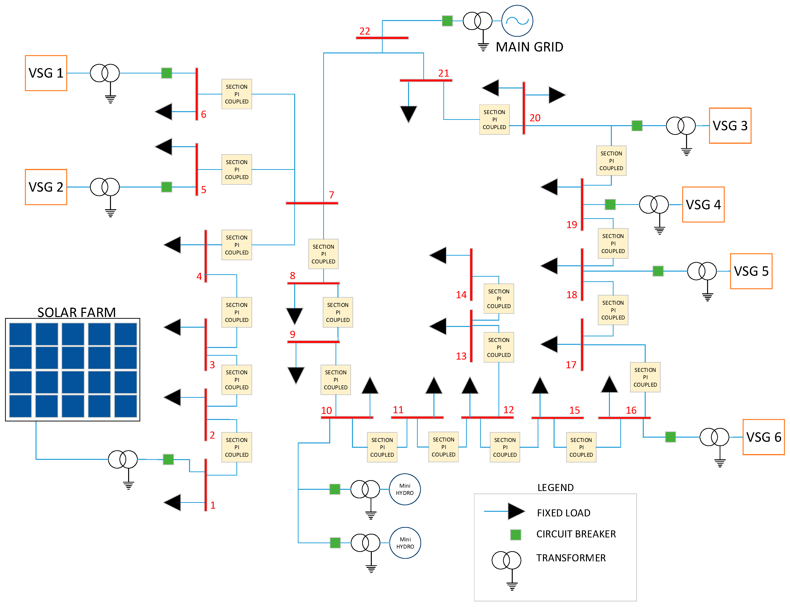
Optimization of the ANFIS using GA has given the controller an optimized range of inertial responses based on real-world simulation. This concept improves both the transient and the oscillation damping of the inertial response of the VSG, which ensures the sustainable and reliable operation of the RES-based DS. The performance of the proposed VSG controller is verified on an 11 kV, 22 bus Malaysian distribution system consisting of two mini hydro and one solar farm. Further, a comparative study has been conducted between the optimized and non-optimized VSG controllers presented to prove the superiority of the proposed controller. The main contribution of this paper is as follows:
Proposed a new way of VSG active power injection through optimizing both the input and output MF of ANFIS.
Through the optimizations, real-time scheduling of values J and D is produced. It managed to cover a wide range of interruptions and able to give appropriate active power responses.
The rest of the paper is arranged as follows.
Section 2 is the methodology for the controller and test system used,
Section 3 is the verification of the controller effectiveness by simulation using PSCAD EMTDC, and finally,
Section 4 concludes the findings of the paper.
4. Results and Discussions
The performance of the controllers was assessed through PSCAD/EMTDC software. The dynamic performance is evaluated using frequency metrics, such as the frequency nadir (FN), frequency spikes, and the damping ratio (DR). The peak-to-peak value for each frequency response should lie within the safe operating frequency of 60 Hz ± 3% Hz [
14]. DR is the measure of the oscillation of a system response. For this simulation, the logarithmic decrement method was used to calculate DR. The best value of DR is known to be
equals 0.7071, where the response is neither too slow nor too oscillatory [
15]. System response with DR < 0.7071 will generate under damped response. While a system with DR > 0.7071 will generate an overdamped response. Under damped response could cause the system to have a prolonged oscillation and cause instability to the system. Comparisons between 4 VSG controllers were made for all scenarios. The controllers are; (i) NO VSG support (NV), (ii) VSG with a fixed value of
J and
D (VF), (iii) VSG with fuzzy inference system controller (VFIS), and (iv) VSG with GA-optimized fuzzy inference system controller (VOFIS). The method used for each controller is shown in
Table 4.
4.1. Scenario 1: Solar Drop 100% for 0.2 s
For the first scenario, the performance of the system was analyzed by turning off the solar power. At the time, t = 8.16 s, solar power was switched OFF for 0.2 s, and solar was switched back ON at t = 8.36 s to mimic the sudden loss of solar power generation. The first transition at t = 8.16 s created an under-frequency event. The second transition at t = 8.36 s was caused by the sudden reconnection of solar power to the DS and created an over-frequency event. During an under-frequency event, energy stored in the VSG was used to minimize the frequency change. During an over-frequency event, VSG absorbed excess power and charged the energy storage in the VSG.
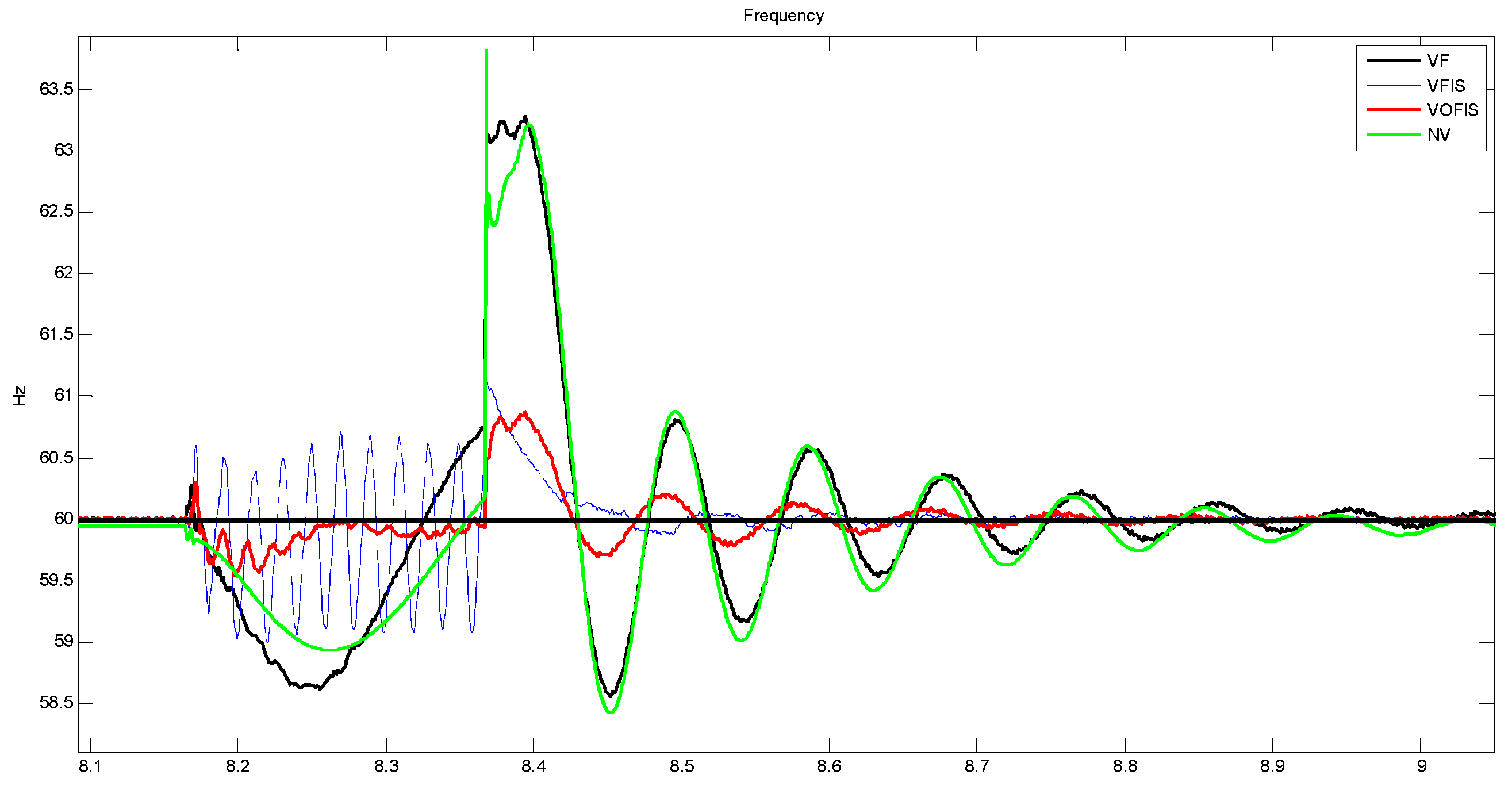
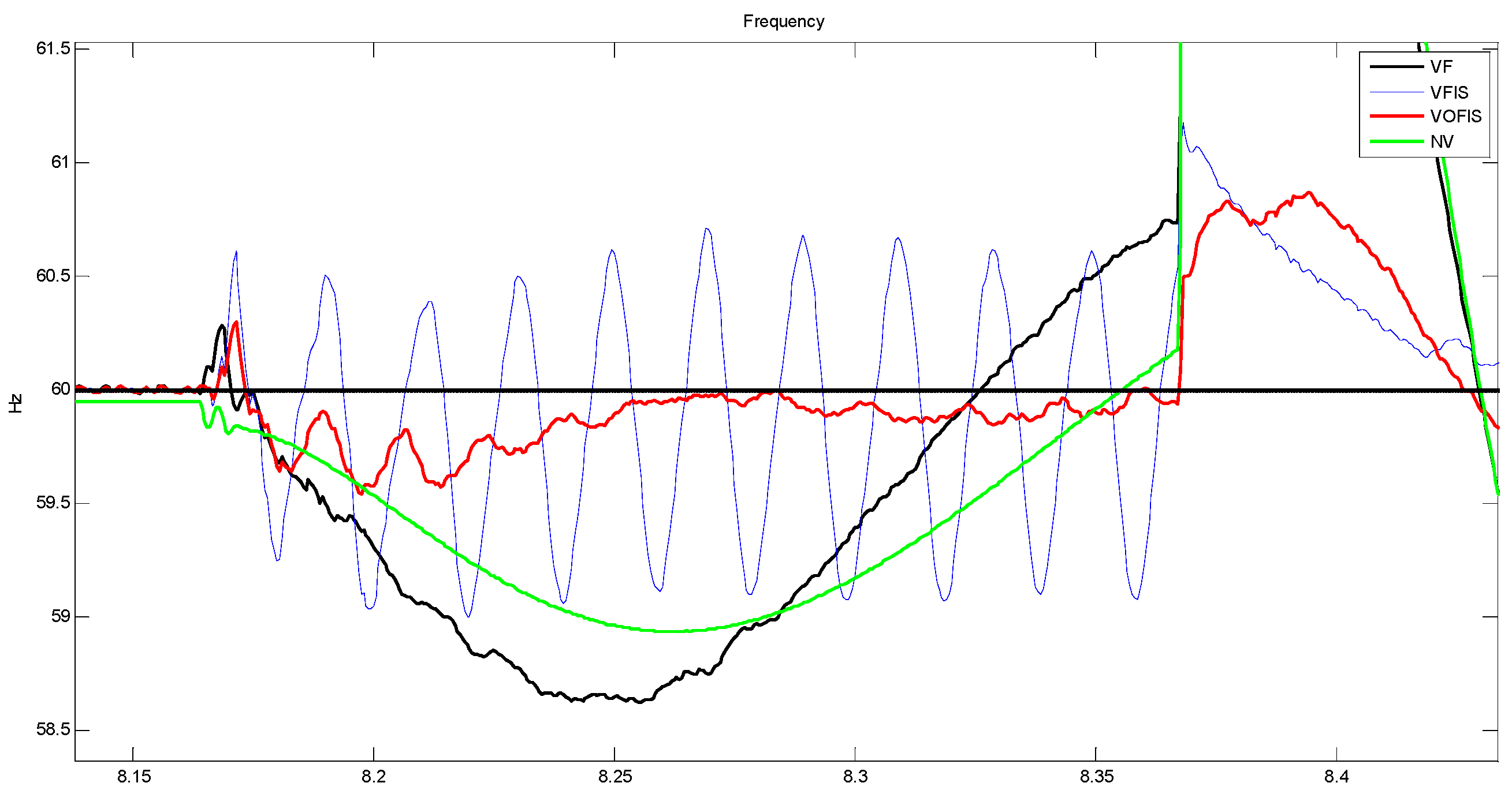
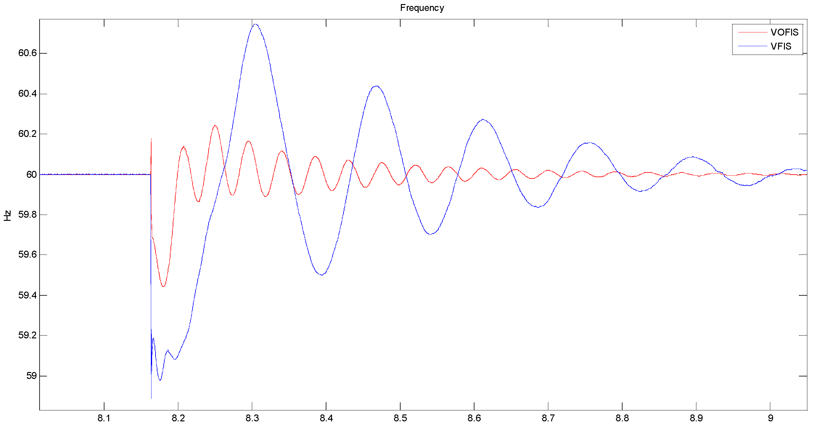
The results in the
Figure 9 and
Figure 10 below show the effect of the sudden switch-off of solar power.
Figure 10 is the zoomed-out version of the result in
Figure 9. From figures, FN for VFIS is 59.09 Hz. Whereas the FN for VOFIS is 59.4 Hz. While FN for both VF and NV are well beyond 48 Hz. Although both the FN for VFIS and VOFIS do not differ much, from a frequency recovery point of view, VOFIS has faster recovery at 70 ms compared to VFIS at 90 ms. The damping ratio (DR) value for VOFIS is 0.856 while VFIS 0.1858. From the results, VOFIS is the best DR value and the highest FN.
At t = 8.36 s, solar power was reconnected and caused an over-frequency event due to the sudden injection of power. VOFIS controller was able to reduce the frequency spike to 60.68 Hz, while the frequency for the VFIS controller spiked up to 62.12 Hz, well beyond the safe frequency operation. During over-frequency events, excess power generated was used to charge the energy storage. It can be concluded that the VOFIS controller was able to absorb more excess power because the controller was optimized to manage a larger range of frequency changes. Besides reducing the peak frequency, VOFIS has the best DR, at 0.8133, as compared to the other controllers in
Table 5.
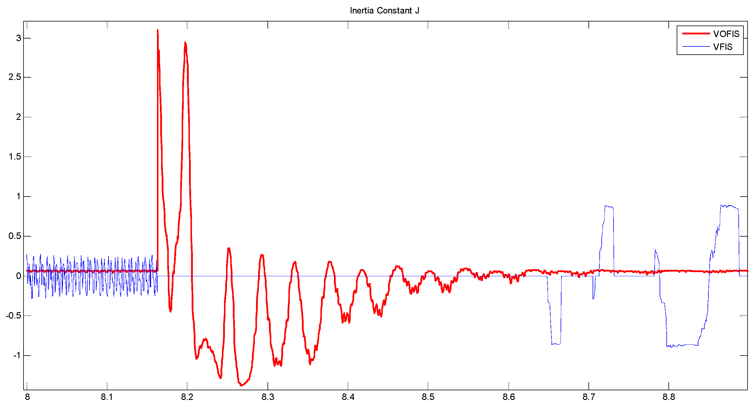
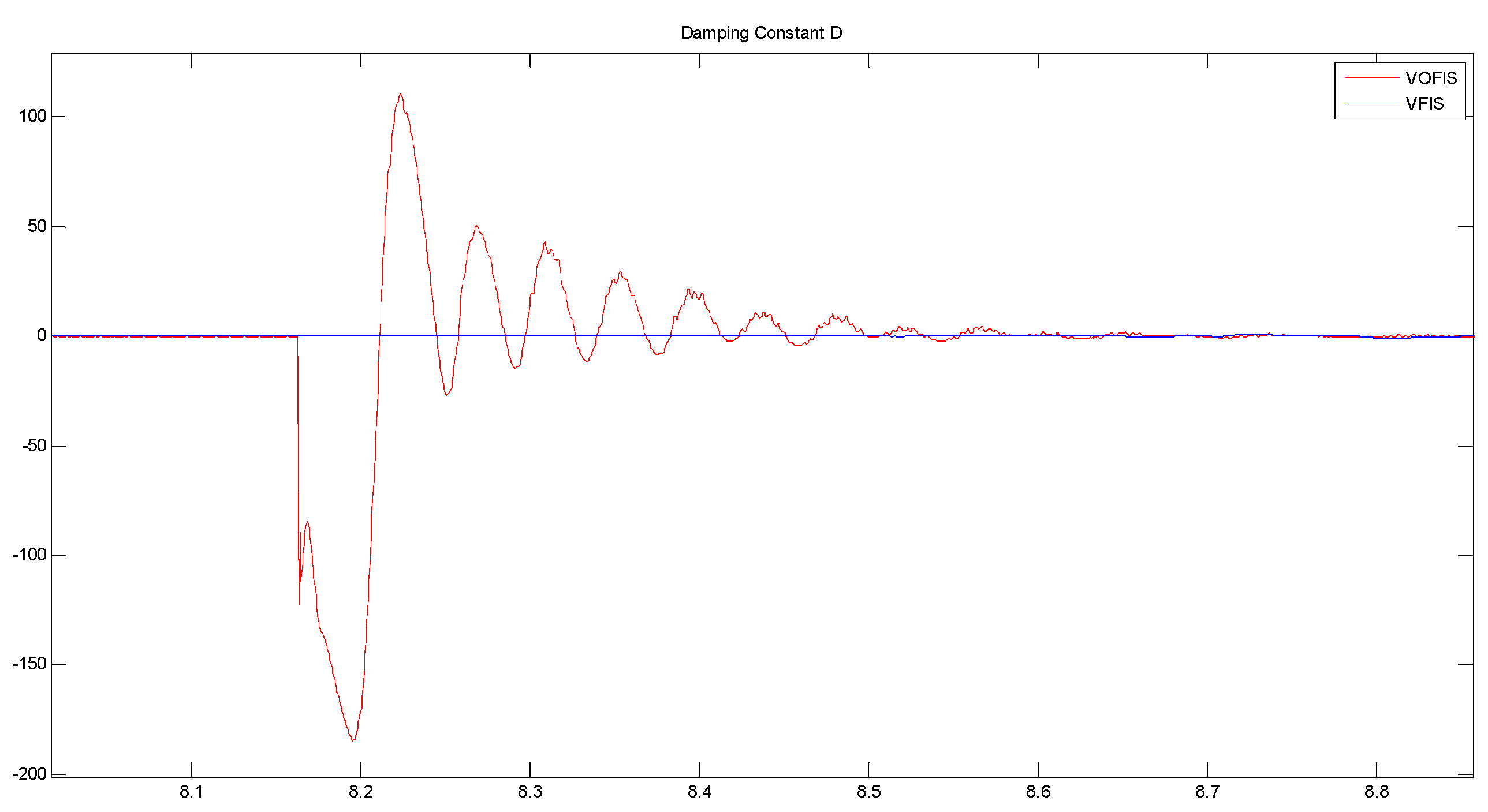
Figure 11 and
Figure 12 show the comparison of the
J and
D value used for the VSG controller.
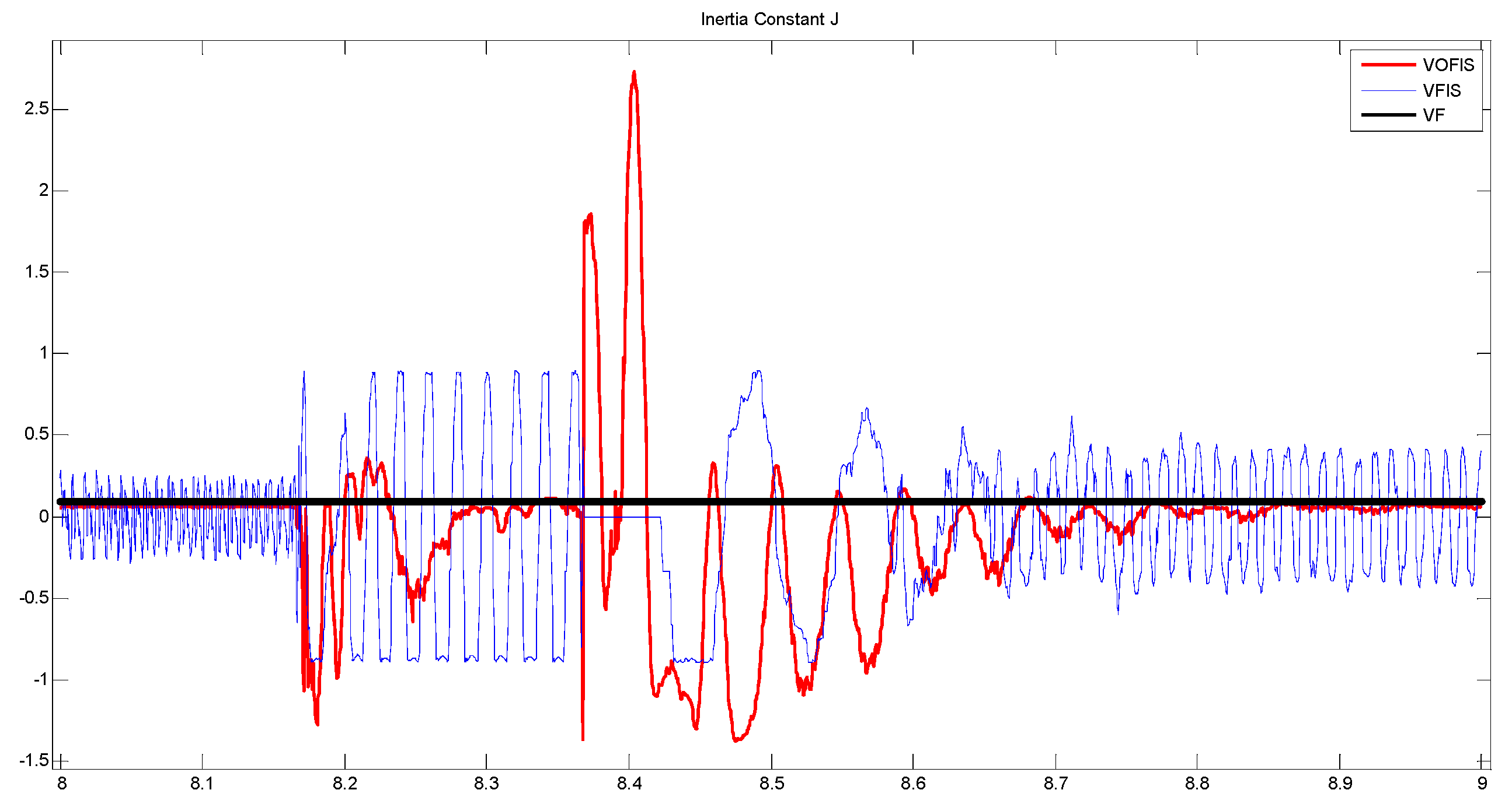
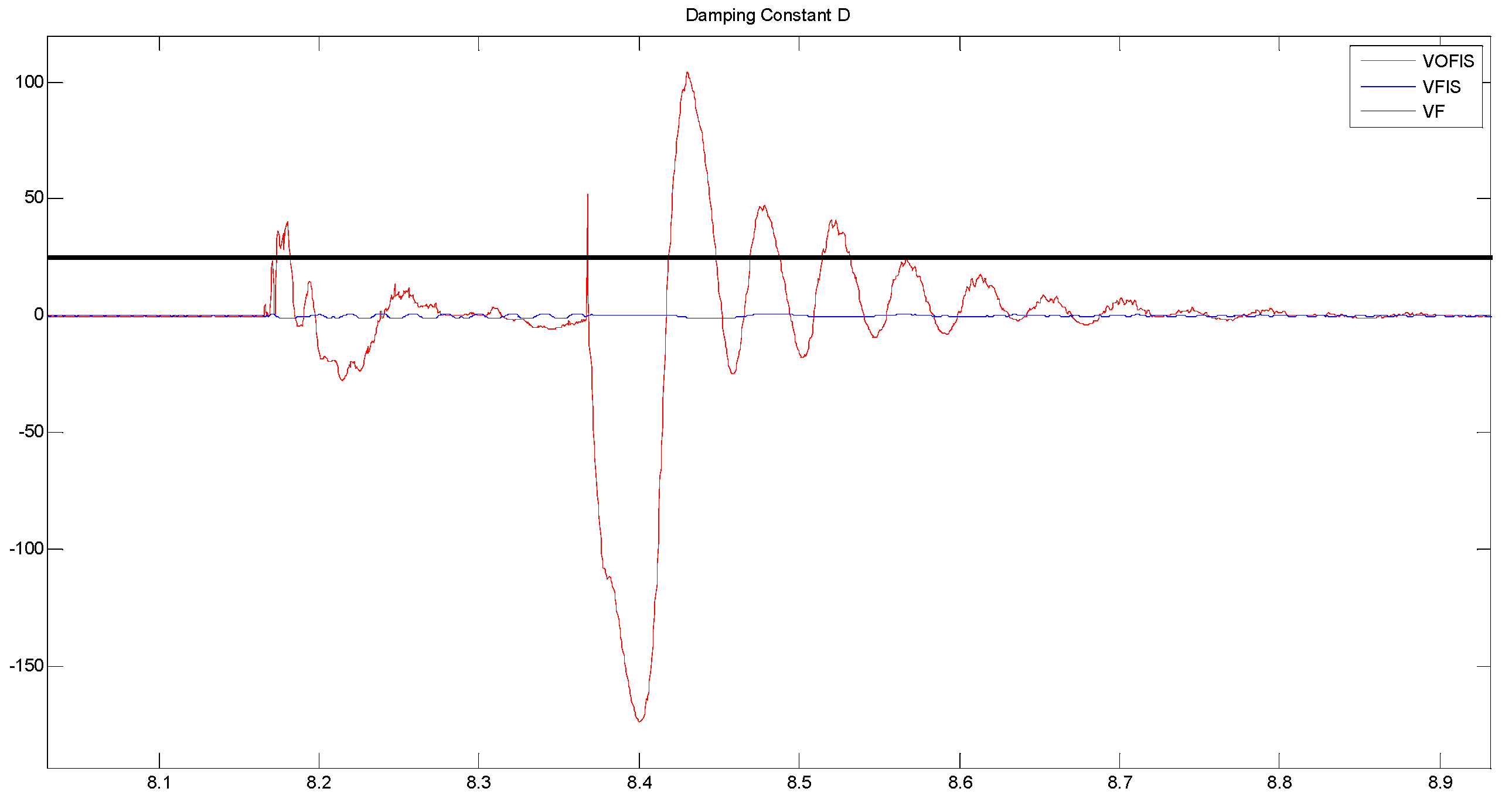
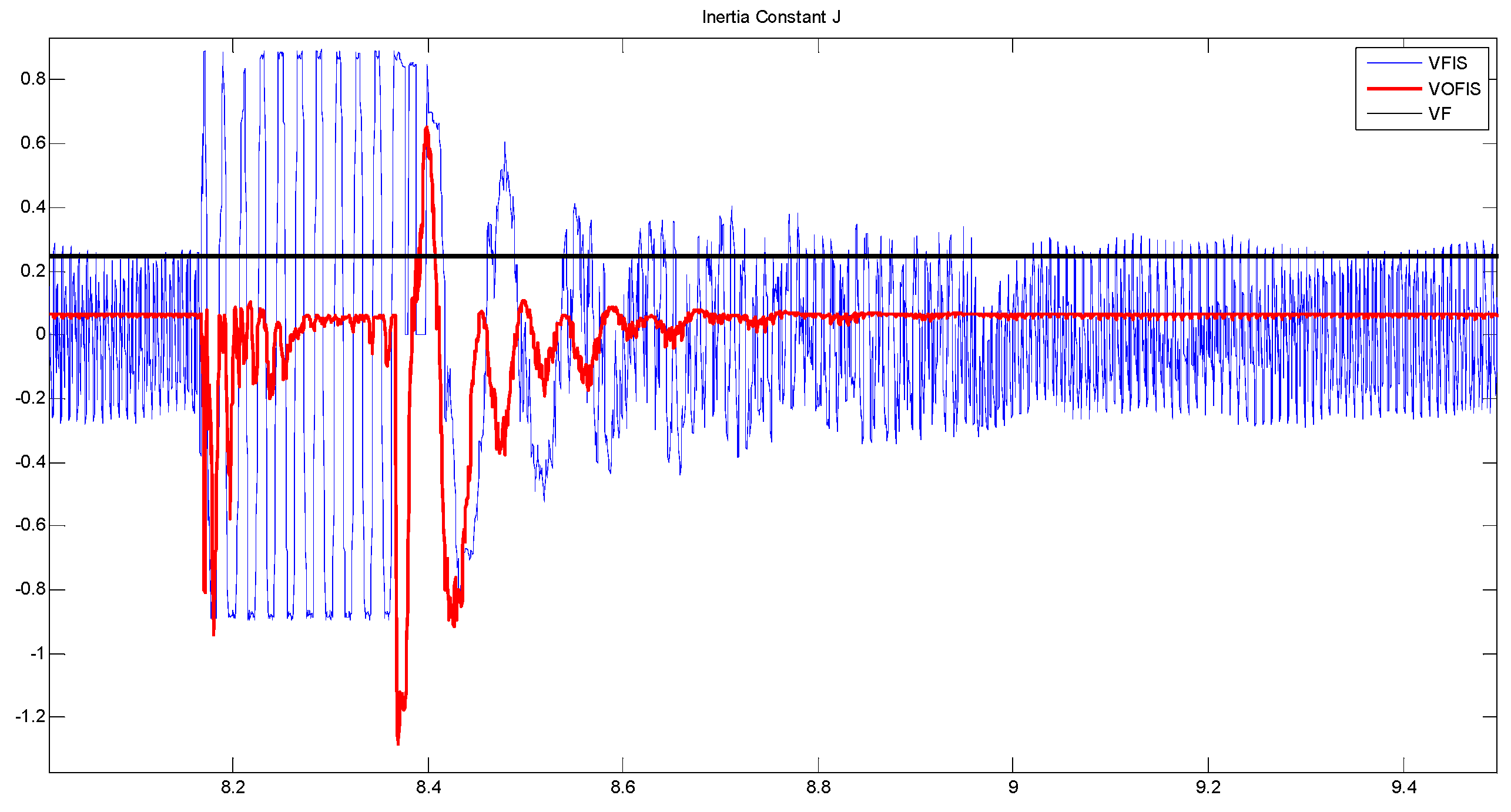
Figure 11 and
Figure 12 compare the difference between VFIS and VOFIS fuzzy controller output. As was anticipated, VOFIS has produced a more accurate value for
J and
D according to the changes in the frequency. VFIS produced an inaccurate value because its MF range was not optimized for the frequency changes.
4.2. Scenario 2: Solar Variation (Irradiance Change)
In this scenario, the transient response of the system was analyzed by varying the solar irradiance after steady state was attained. At a steady state, solar irradiance was maintained at 900 W/m2 generating 1.32 MW from PV farm. Solar irradiance changes from 900 W/m2 to 100 W/m2 at 8.16 s for 0.2 s while retaining the temperature of the solar panel, which was set at 40 °C. This scenario simulates the intermittent nature of a solar farm. As a result, power generated from PV farm dropped from 1.32 MW to 0.2 MW, subsequently causing an under-frequency event due to power deficit. At t = 8.36 s, the solar irradiance changes from 100 W/m2 back to 900 W/m2. At this point, an over-frequency event occurs due to the sudden injection of solar power.
Both
Figure 13 and
Figure 14 shows the frequency response of scenario 2, where
Figure 14 is the zoom-out version of
Figure 13. From figures, FN for VOFIS dropped to 59.56 Hz, while for VFIS, the frequency dropped to 59.03 Hz with a high oscillating pattern. VOFIS recovers the frequency faster at 100 ms compared to VFIS at 2 s. From
Table 6, DR for VOFIS and VFIS is 0.5208 and 0.0849. This proved that VFIS produced a high oscillation response compared to VOFIS. Therefore, the transient response for VFIS is longer compared to VOFIS. DR for both VF and NV is lower than 0.01. At t = 8.36 s, VOFIS reduced the over-frequency spikes to only 60.9 Hz compared to VFIS 61.5 Hz. With a VF controller, the frequency spike up to 63 Hz. The ability of the VOFIS controller to absorb excess power and use them to charge the energy storage reduced the frequency spike.
Figure 13 shows that frequency recovery using VOFIS is faster and smoother as compared to the other controller.
Figure 15 shows the comparison between the value and range of
J and
D between VOFIS and VFIS. The value of
J and
D for VOFIS is optimized and fine-tuned according to the changes in the frequency. As a result, VOFIS able to inject and absorb sudden changes in the power hence maintaining the system frequency within the safe operation.
Figure 15 and
Figure 16 compare the fuzzy output value for VFIS and VOFIS.
4.3. Scenario 3: Islanding Event
In this scenario, DS was islanded at time t = 8.16 s by opening the main grid circuit breaker.
Figure 17 shows that VOFIS can reach stability without overshooting beyond safe frequency operation. VFIS, on the other hand, could not react to the islanding event. This could be seen from the value of
J and
D in
Figure 18 and
Figure 19. The controller was unable to produce a new variation of
J and
D as the frequency detected is out of the input MF range. Both
J and
D were set to zero during the islanding process. On the other hand, VOFIS reacted and reduced the frequency changes during the inertial phase. The FN for VOFIS dropped to 59.44 Hz while 48.87 Hz for VFIS. As shown in
Table 7, the DR for VFIS is overdamped at 9.163, while DR for VOFIS is underdamped at 0.203. Even though the DR for VOFIS is underdamped, the response time for the frequency to stable. VOFIS recovers 7 s after islanding while VFIS 9 s after.
5. Conclusions
In this paper, a new active power controller for VSG has been developed based on ANFIS, in which membership functions are optimized using GA. The values of inertia constant, J, and damping constant, D, in a VSG controller are controlled through the proposed controller to ensure the improved operation of the VSG controller. Through the simulations conducted in the PSCAD platform on an 11 kV Malaysian practical distribution system for various cases, it has been proved that the proposed ANFIS-GA-based controller has improved the performance of the VSG compared to the conventional VSG controller.
From the simulation results, it has been observed that the proposed controller managed to maintain the DS frequency within the safe operating limit of 60 ± 1.8 Hz, better transient response, and faster recovery time during all the three cases (100% solar drop, solar irradiation changes, and islanding event). VOFIS able to recover the frequency 22% faster compared to the other controllers.
From the analysis of the above results, it can be concluded that the values of J and D for the proposed VOFIS are optimized and fine-tuned according to the changes in the frequency. As a result, VOFIS able to inject and absorb sudden changes in the power hence maintaining the system frequency within the safe operation. This paper serves as an initial work for coordinating multiple energy storage systems in VSG as an ancillary service to the DS. Furthermore, different types of metaheuristic optimization should be implemented and compared to obtain the best method for VSG application. Optimization of J and D constants in the VSG controller plays a vital role in regulating the VSG power output to maintain stable frequency operation during islanded DS operation. Without the help from VSG as an ancillary service, DS could not maintain the frequency in the safe operating region, which may result in the malfunction of DS. Therefore, it can be said that through the implementation of the proposed optimized GA-ANFIS-based VSG controller, the sustainable and reliable operation of DS has been ensured.
