Article

Decontamination and Remediation of Underground Holes and Testing of Cleaning Techniques Based on the Use of Liquid Cold Decontaminant

1
INAIL—Italian Workers’ Compensation Authority (Research Division), 00143 Rome, Italy
2
WOW Technology S.p.A., 35043 Monselice, Italy
3
Department of Astronautical, Electrical and Energy Engineering (DIAEE), Sapienza University of Rome, 00186 Rome, Italy
4
LIVANOVA SM Subsidiary of LivaNova PLC, London W2 6LG, UK
5
WAVE s.n.c., Via Principi d’Acaja 14, 10138 Turin, Italy
*
Author to whom correspondence should be addressed.
Sustainability 2022, 14(17), 10565; https://doi.org/10.3390/su141710565
Submission received: 7 July 2022 / Revised: 14 August 2022 / Accepted: 17 August 2022 / Published: 24 August 2022
(This article belongs to the Section Resources and Sustainable Utilization)

Abstract

:
As part of its institutional skills, the INAIL (National Institute for Insurance against Accidents at Work) promotes and carries out activities aimed at preventing the risks to which workers may be subjected to in different work scenarios, in this case, in collaboration with Livanova and WOW Technology S.p.A. (Wonderful Water Technology, Monselice, PD, Italy). An open problem at the Livanova plant, located in Saluggia (VC, Italy), is the decontamination of many concrete structures. Precisely because of its radioactive content, simple mechanical removal wasn’t possible for the high production of the contaminated dust, which may endanger the health of workers. The solution adopted was to insert decontaminant liquids into the concrete structures and, after a period of soaking, treating these liquids with an evaporative machine that is able to separate contaminants. The combination of these systems proved to be suitable for this experimental decontamination activity. As a result, this activity has shown a certain efficiency in removing radioactivity from the walls of the structures, ensuring the safety of the workers involved during the operations and reducing the potential risk of exposure in comparison to mechanical removal.

1. Introduction

One of the most studied problems in nuclear decommissioning is the decontamination of concrete structures containing radioisotopes, and this problem occurred on a repository located on Saluggia (VC), in Italy, operated by the company Livanova. The experimental activity carried out consisted of the decontamination of the concrete walls of 38 holes, in which there were stored, for many decades, a number of radioactive sources (actually removed) used for various purposes (ex. production of radiopharmaceuticals). For the high dose rates due to radioactivity present in these structures, to avoid contamination risks to operators and to keep the site in a safe state, it was decided that the use of classic, mechanical methods was not possible. This is due to the generation of contaminated dust able to remain in suspension in the air, spreading everywhere, and in this way, increasing the exposure risks for both external and internal contamination.
From the beginning, various strategies and techniques developed over the years (a review of them can be found in [1]) have been taken into account for this activity, [2,3], including biological decontamination [4], chemical treatments (such as selective absorption and other) [5,6], and thermal technologies [7].
There were also some new experimental technologies considered: exploiting substances called PBAs (Prussian Blue Analogues) for the strong adsorption of Cs+ ions (highly present in this activity), the use of magnetic nanoparticles (that could also be PBAs) coated with cationic polymers [8,9,10], or also, the use of electrokinetic decontamination systems [11], but their TRLs were too low for this industrial operational context.
Finally, the experimental decontamination process chosen takes advantage of various fluids (mainly water) that have a certain radionuclide extraction capacity [12,13]. They will be treated with an evaporative machine (called the WOW machine), which minimizes the final radioactive waste and turns it back into solid form. The idea for this “wet” decontamination is to work under the water head to contain contaminated dust, reducing risks for operators.
The aim of this experimental activity is the development of specific guidelines containing safety procedures addressed to operators of plants, taking into account recommendations, regulations, and laws [14,15,16].
The results relating to the risk of internal contamination of operators and the surrounding environment revealed that, thanks to this wet decontamination process, the suspension in the air of contaminated dust was very low, and this allows for the reduction of exposure for workers and the improvement of intervention times and decontamination-process performance. Costs of operations could also be reduced indirectly.
Describing the structures, the holes in question were divided into two groups of 19 elements, and they are located under two different sheds (to distinguish them, holes are named with letters from A to U and numbers from 1 to 19). The task is of particular interest because the shafts (whose construction dates back to decades ago) were made in concrete and not in stainless steel, as they should have been for the temporary storage of radioactive sources. The Figure 1a,b shows the geometry and the disposition of the holes for one shed. (The other one is the same.)
The machine used for liquid treatment was patented by WOW Technology S.p.A., and the scheme of this pilot plant is shown in Figure 2.
This machine uses an evaporation/distillation process, optimized with fluid dynamics analysis, to separate the solvent from the solute and the suspended, solid particles.
The evaporation is a single-stage process, with a continuous mass flux (no batch) and with the maximum concentration control [17,18,19].
The boiling process inside the device, named WOWPUT-101, takes place at a temperature of 117 °C (±0.5 °C) and a pressure of 1.90 (±0.5) bar absolute.

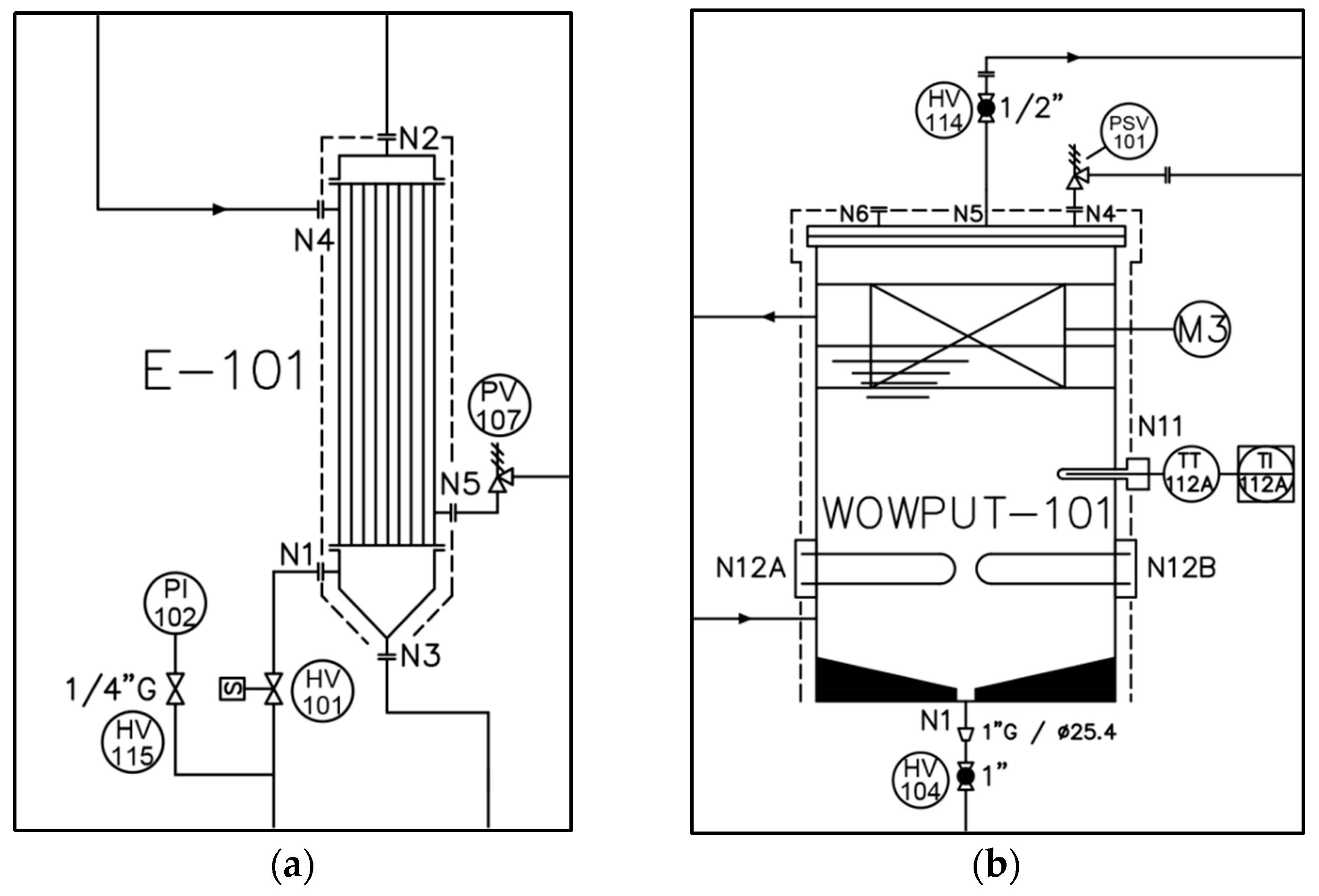
2. Description of the Work Progress

The experimental activity consisted of 2 basic steps: hole decontamination and liquid-waste processing. In addition, a final control on the achieved results was performed.
The decontamination objective was the reduction of residual surface contamination (in Bq/cm2) penetrated into the concrete holes. Radionuclides present were 137Cs (for the most part), 60Co (revealed in trace amounts), 241Am (revealed in trace amounts), and 90Sr.
Initially, the facility was set up on site to test the evaporating process, and for this, there was a preliminary hole selection on the basis of chemical and radiological characteristics.
The holes selected for the preliminary tests were identified with ‘L’, ‘R’, and ‘U’.
After these tests, the activity was extended to all the holes.
Radiological characteristics are reported in Table 1.
The initial effective dose rate was measured and calculated [20] only in the internal cap of the holes because of the high levels of radioactivity, due to the strong contamination.
The decontamination process of concrete began by filling holes with water and/or diluted decontaminant liquids (saline and/or weakly acid solutions), which were removed after 24 h, and this was repeated many times to extract the maximum possible amounts of radioisotopes.
The contaminated water solutions were sent to the machine, and radionuclides were concentrated using the evaporative WOW process, separating in this way as much 137Cs, 60Co, 241Am, and 90Sr as possible. (This paper is focused principally on 137Cs and/or β emitters concentration because 241Am concentration was too low.)
The final estimated sludge volume was about 0.1 m3, consisting of water and organic decontaminating agents. As mentioned before, the entire evaporation process took place at a temperature of 115–118 °C and at a pressure of 1.85–1.95 bar absolute.
During the process, radioactive fluids were sampled to verify the decontamination stages and the cleanliness degree.
Finally, for this experimental activity, there was the cleaning of the machine with some detergents.
The completion of the work involved a final phase in which the cleaned holes were coated first with a layer of adhesive primer towards the surfaces and then a second layer of elastic, waterproof, and mechanically resistant epoxy resin. After that, a final check on the surface contamination was done in each hole and on the floor and walls of the sheds.
To ensure effectiveness over time, periodic control was planned from the end of the work (quarterly surveys for a period of one year).

3. Results

3.1. Holes Decontamination Results

3.1.1. Holes Results

The final verification was done through the verification of the residual, removable surface contamination and the measurement of the external dose in each hole.
After the decontamination process, the effective dose-rate levels were all decreased, but the superficial activity levels of some holes were too high; for safety reasons, it was decided to cover the holes with special paints, fixing and decreasing (in this way) the residual contamination on the surfaces (leaving the effective dose rate unchanged).
After this operation, in some holes, activity reached levels under the MDA (Minimum Detectable Activity).
In Table 2 the final results of these operations are shown.
In this case, the effective dose rate was measured in the internal cap in order to have a comparison with the first measurements made.
In Figure 3 and Figure 4 are the dose rates, respectively, before and after the decontamination process.

3.1.2. Specific Holes Results

Here, the results of two holes, U and R, which had, at the beginning, distinct levels of contamination, are evaluated. Preliminary tests were run on hole U, as representative of the holes with very low contamination.
It showed a high reduction of both the contamination in the resulting liquids between the first and the second washing (with simple demi water) and the removable surface contamination (walls and bottom of the hole). The results are in the tables below (respectively Table 3 and Table 4).
When it came to Hole R, as the representative of the intermediate/high contamination, it was pointed out that the washing cycle was repeated several times with water; the following table shows the results of the analysis on the waste water after the washing cycles and the removable surface contamination (data relating to 137Cs).
The trial provided the data in Table 5 and Figure 5; the latter shows the trend of 137Cs extracted after considering many washes.
Figure 5 shows a certain downward trend, except for the washing of n°4. This fact is related to the soaking time because for every case, it was about 1 day, except for n°4, which was about 3 days. The slight descent is due to the fact that there was still an unknown amount (but rough estimate) of residual activity within the structure. Taking a weighted average of the hole contamination, there is an activity reduction, but considering the walls and the bottom separately, it is possible to notice that the activity concentration in the bottom increases. This means that there was an important penetration of 137Cs into the cement that the washing process was able to progressively extract. (This is also shown and demonstrated by the trend in Figure 5.)
There were many holes with the same problem, and this was another reason to fix the residual activity on the holes.
The contribution of the effective dose didn’t vary after painting the holes, but surface contaminations were drastically reduced, as can be seen, for example, in Table 6 and Table 7 (that consider the U and R holes).

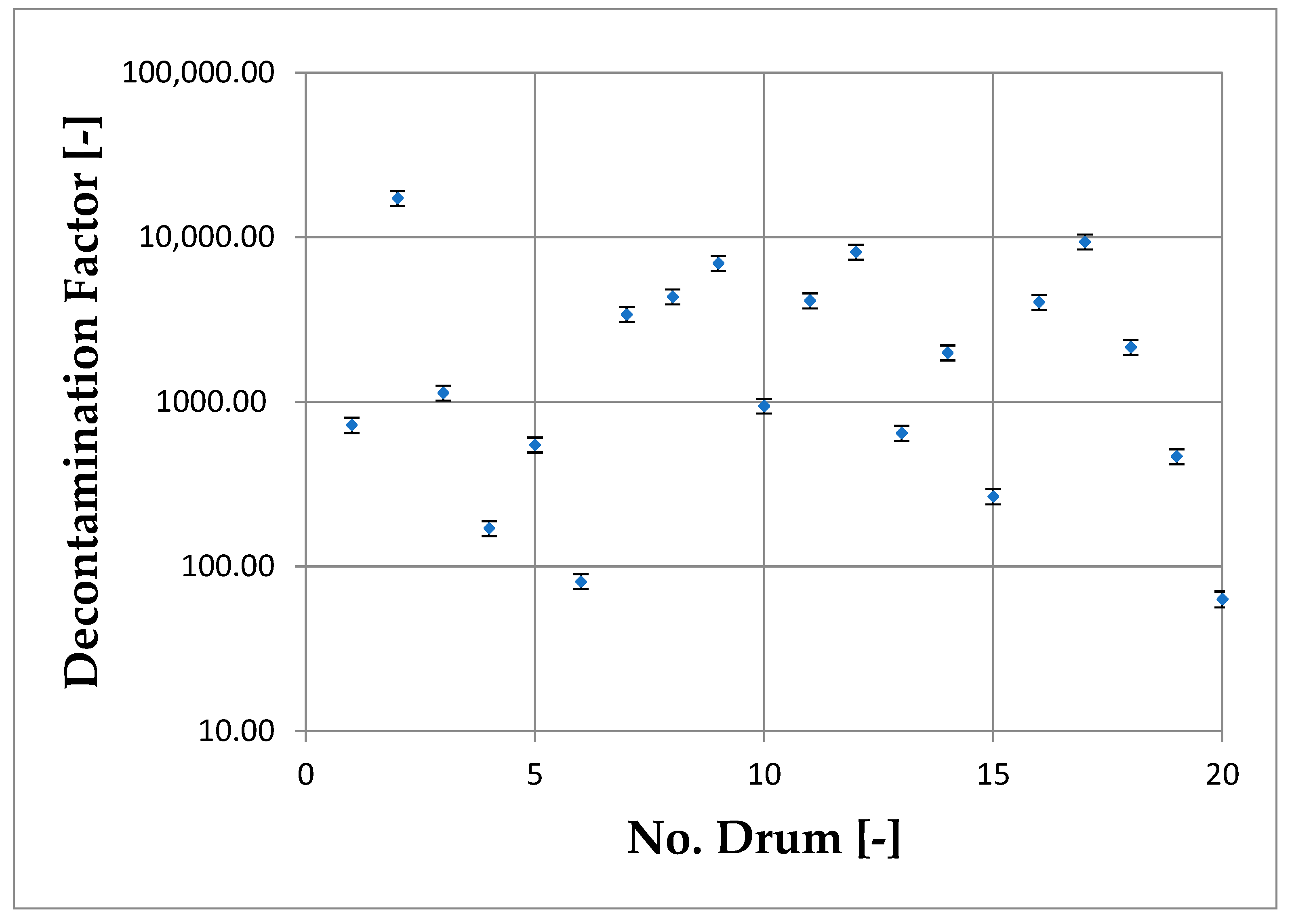
3.2. Evaluation of WOW Machine Decontamination Factor

Radioactive liquids from the holes were treated with the WOW machine.
The liquids were collected in 20 different drums, and every drum was processed by the machine. The activity concentration was measured both before and after the treatment, and the decontamination factor ( D F ) and the decontamination removal efficiency ( D E % ) of the machine can be calculated with following formulas [21]:
D F = C i n C o u t
D E % = ( 1 1 D F ) 100
Results are shown in Table 8 and Figure 6.

4. Discussion

With regards to the overall safety of the plant, one problem that arose was the entrainment of solid elements (mainly sand and mud) derived from the cleaning of the cement and the precipitation of solid particles as a chemical reaction between the elements contained in the contaminated structures and the decontaminant used.
These elements could induce the formation of deposits inside the pipes, causing dangerous, localized overheating and creating overall instability in the system.
The first solution to prevent this problem was the use of a filtering system located on the machine inlet.
The sediments, suspended solid fractions, and any biological presence or other forms present (>90 µm) were blocked by a metal, mesh cartridge filter (AISI316L) of adequate size to predict, andalso, to contain the residual sludge on the bottom of the input tanks., (In this case, the cartridge dimensions were ø 70 mm × 200 mm.)
This filtration system, placed upstream of the machine, protects even the peristaltic lung of the inlet pump (P-101) from premature deterioration, due to the mechanical actions of sand and the like (which cause abrasions), and reduces the amounts of deposits inside the boiler and in the exchanger (E-101), which is the most sensitive component in the formation of encrustations.
In the last component, the heat was transferred from the steam exiting the boiler to the incoming liquid through the shell/tube bundle system.
The tube bundle was subjected to a thermal gradient (ΔT = 70 ÷ 90 °C), and in this situation, carbonates and silicates could precipitate at certain temperature and pH conditions [22,23], adhering to the hot tubes surface and decreasing the internal diameter.
The solution developed in order to avoid this situation of tube bundle occlusion was a cleaning cycle performed routinely, using a mixture of carboxylic acid and co-formulants (whose name is Zero Pi Universal Degreaser and whose IP is of WOW Nuclear).
The solution characteristics are shown in the Table 9.
The decontaminant agent also contained surfactants and a weak natural solvent.
This mixture was circulated at a concentration of 100% v/v in a closed loop at room temperature for heat exchangers (by closing valves HV-107 and opening valve HV-111, shown in Figure 7a), while it circulated at a maximum temperature of 115 °C for the boiler’s inner part (shown in Figure 7b) at a concentration of 6% v/v in regular functioning mode.
The closed-loop mode described uses the pump and the piping of the existing system, and the process duration is based, by experience, on the type and quantity of radioactivity accumulated on the internal walls of the machine during the decontamination service.
The control of the accumulation of encrustations is guaranteed by a pressure sensor located downstream of the exchanger, which detects the small difference in pressure caused by the narrowing of the tube-bundle internal diameter.
This pressure switch signals to the control system the problem, which is solved with extraordinary maintenance.
The system was designed and built with the logic of oversizing and management of all possible countermeasures for any type of failure, and this was in order to increase the machine safety by protecting it from corrosion, overpressure, overheating, and extreme mechanical stress.
The detection system of malfunctions, abnormal temperatures, and pressures used had a certain tolerance set a priori to include the ripple of these last two parameters— that is, around 5% of the values that are present due to the linearity of the controlled feedback system.
There were suggested improvements that would prevent the stop of the device.
One of the enhancements suggested was a temperature monitoring system (consisting of thermal imaging cameras or thermocouples) installed in specific points of the system which, through a network of sensors, reliably makes the measured parameters available in addition to existing temperature sensors.
The solution that involved the installation of thermal imaging cameras was preferred over that with thermocouples, as it allowed us to observe the trend of temperatures over the entire extension of the pipes and localized variations [24].
Thermographic investigations allowed both the continuous inspection of the pipes and the identification of the precise position of the possible obstruction that was going to be in the formation (the problematic area, i.e., the obstructed one, will appear clearly on the infrared image produced by the instrument) during the operation of the system.
This enabled a scheduled shutdown of the system and the replacement of the defective component or the activation of countermeasures, such as the isolation of the interested part through existing valves and circulation of an appropriate decontaminant liquid in a closed loop to remove encrustations.
From a practical point of view, the thermal imaging cameras must be a few meters away from the pipeline to be monitored, in order to allow, during operation, the fixed measurement of the temperature along the entire extension of the pipeline.
In addition, the possibility of intervention could be needed to add specific safety devices, with the purpose of assisting the decision of a preventive shutdown of the equipment when a critical fluid temperature threshold is reached, in order to activate extraordinary maintenance, improve the sensitivity of the machine, report the correct functioning of the system, and prevent damage of pipes caused by unexpected lack of circulation.
Despite the decontamination and subsequent painting of the holes, it is noted that, after the treatment, the concentration of activity on the bottom was higher than the concentration of activity on the walls, in most cases.
A possible explanation is that, during soaking, part of the contamination settled on the bottom, and at this point, was affected both by the solvent extraction from the bottom and by contamination extracted from the walls and consequently precipitated.
To avoid the possibility of this happening in future works, an automated system that uses a metal disc placed on the bottom to collect the contamination can be provided, thus proceeding with the decontamination of the walls. (For the bottom, it is not a problem, since when fixing contamination through paints, the contribution of the activity was drastically reduced.)
At the end of the processes, taking into consideration the initial activity concentration of 137Cs, which enters the machine for the treatment, and the volume of liquid waste in the drums, the activity removed from the holes was calculated (Table 10).

5. Conclusions

In conclusion, it can be said that the experimental work has proved that the method applied is consistent, especially with regards to the safety aspects for the operators; even in the presence of contaminants to a greater extent than expected, the resulting doses are in line with the initial dose assessment.
In particular, the data available allows us to give positive feedback on some of the initial project goals, which are the containment of doses for the personnel assigned to decontamination, due to the effectiveness of the water shielding (working under the water head considerably reduces the doses to the operators because of the radiation self-shielding of the solutions), the reduction of external contamination by dust (measured through hand–foot checks on operators), and the reduction of the risk of internal contamination (measured through environmental sampling of the air and measurements on excreta).
The measurement plan was found to be robust and effective, particularly for the consistency between the total β determinations and the 137Cs values measured in gamma spectrometry.
After water decontamination, it is possible to affirm that cleaning by washing has proved to be much more effective than mechanical dry removal: the measured activity in the washing water (that is, the quantity of radionuclides extracted from the cement surface) is much higher than those removed by the rub test; the use of water and/or acids further increases the extraction capacity, even with respect to brushing. (Use and efficiency evaluation of different decontaminants will be the next research work.)
The total activity removed was about 120 MBq. However, a rough estimate that considers both the uniformity of the distribution of the source and an average depth of penetration into the surface about 2 cm suggests that the contamination removed is about four-fifths of the total contained in the structures.
Despite the high effectiveness of the process and the machine, it was not possible to achieve the total elimination of residual contamination from these adsorbent surfaces, and this was due to the high values of contaminants present inside the holes; however, this level is considered enough for the safety of the workers.
The arrival point is understood as a very favorable condition for the final safety of the site, fixing the residual contamination to quite a considerably lower level.
Although the decontamination of the holes has not eliminated all of the activity concentration, the contaminated water treated by the WOW machine is instead, almost completely cleaned (and in a large part, releasable, according to the rules established by Italian laws [16]).
In fact, considering the decontamination factor and the decontamination removal efficiency of this machine, thanks to the evaporative process, it was possible to eliminate most of the contamination from the liquid used in the holes.
In conclusion, the last consideration is that the volume of waste was minimized after the treatment with the machine. The initial volume of liquid waste was about 1936 L, and after the treatment with the machine, the liquid waste that remained was about 90 L. The residual volume reduction factor, which is the ratio between the initial and final volumes, suggests that the initial volume was reduced about 22 times at the end of the process.

Author Contributions

Conceptualization, A.M. and M.M.; Formal analysis, P.M.; Investigation, P.P., C.L. and A.P.; Project administration, A.T.; Supervision, F.G.; Writing—original draft, F.R. and F.M. All authors have read and agreed to the published version of the manuscript.

Funding

This research received no external funding.

Institutional Review Board Statement

Not applicable.

Informed Consent Statement

Not applicable.

Data Availability Statement

Not applicable.

Conflicts of Interest

The authors declare no conflict of interest.

References

  1. Liu, S.; He, Y.; Xie, H.; Ge, Y.; Lin, Y.; Yao, Z.; Jin, M.; Liu, J.; Chen, X.; Sun, Y.; et al. A State-of-the-Art Review of Radioactive Decontamination Technologies: Facing the Upcoming Wave of Decommissioning and Dismantling of Nuclear Facilities. Sustainability 2022, 14, 4021. [Google Scholar] [CrossRef]
  2. Dickerson, K.S.; Wilson-Nichols, M.J.; Morris, M.I. Chapter 3, Candidate Technologies for Concrete Decontamination. In Contaminated Concrete: Occurrence and Emerging Technologies for DOE Decontamination, 1st ed.; U.S. Department of Energy Office of Environmental Restoration and Waste Management Office of Technology Development: Washington, DC, USA, 1995. [Google Scholar]
  3. Laraia, M. 14—Innovative and conventional decontamination techniques for cementitious structures. In Sustainability of Life Cycle Management for Nuclear Cementation-Based Technologies; Woodhead Publishing Series in Energy; Woodhead Publishing: Thorston, UK, 2021; pp. 455–512. [Google Scholar] [CrossRef]
  4. Prakash, D.; Gabani, P.; Chandel, A.K.; Ronen, Z.; Singh, O.V. Bioremediation: A genuine technology to remediate radionuclides from the environment. Microb. Biotechnol. 2013, 6, 349–360. [Google Scholar] [CrossRef]
  5. Arnal, J.M.; Sancho, M.; García-Fayos, B. Treatment of 137Cs contaminated water by selective adsorption. Desalination 2013, 321, 22–27. [Google Scholar] [CrossRef]
  6. Awual, M.R.; Suzuki, S.; Taguchi, T.; Shiwaku, H.; Okamoto, Y.; Yaita, T. Radioactive cesium removal from nuclear wastewater by novel inorganic and conjugate adsorbents. Chem. Eng. J. 2014, 242, 127–135. [Google Scholar] [CrossRef]
  7. Oh, M.; Lee, K.; Foster, R.I.; Lee, C.H. Feasibility study on the volume reduction of radioactive concrete wastes using thermomechanical and chemical sequential process. J. Environ. Chem. Eng. 2021, 9, 105742. [Google Scholar] [CrossRef]
  8. Jang, S.C.; Hong, S.B.; Yang, H.M.; Lee, K.W.; Moon, J.K.; Seo, B.K.; Huh, Y.S.; Roh, C. Removal of Radioactive Cesium Using Prussian Blue Magnetic Nanoparticles. Nanomaterials 2014, 4, 894–901. [Google Scholar] [CrossRef] [PubMed]
  9. Kim, M.; Park, J.H.; Lim, J.M.; Kim, H.; Kim, S. Conventional and photoinduced radioactive 137Cs removal by adsorption on FeFe, CoFe, and NiFe Prussian blue analogues. Chem. Eng. J. 2020, 405, 126568. [Google Scholar] [CrossRef]
  10. Delchet, C.; Tokarev, A.; Dumail, X.; Toquer, G.; Barré, Y.; Guari, Y.; Guerin, C.; Larionova, J.; Grandjean, A. Extraction of radioactive cesium using innovative functionalized porous materials. RSC Adv. 2012, 2, 5707–5716. [Google Scholar] [CrossRef]
  11. Kim, G.N.; Choi, W.K.; Lee, K.W. Decontamination of radioactive concrete using electrokinetic technology. J. Appl. Electrochem. 2010, 40, 1209–1216. [Google Scholar] [CrossRef]
  12. IAEA. Combined Methods for Liquid Radioactive Waste Treatment—Final Report of a Coordinated Research Project 1997–2001; IAEA-TECDOC-1336; IAEA: Vienna, Austria, 2003. [Google Scholar]
  13. Narbutt, J. Chapter 4—Fundamentals of Solvent Extraction of Metal Ions. In Handbooks in Separation Science-Liquid-Phase Extraction; Elsevier: Amsterdam, The Netherlands, 2020; pp. 121–155. [Google Scholar] [CrossRef]
  14. Pianese, E.; Mazzaro, M. Radiological decontamination procedures in emergency operations. ANPEQ Newsletter n17-72/May–December, 2005, Year XXV n 2–3. Available online: https://anpeq.it/index.php/117-notiziario-626541/notiziario/281-2005 (accessed on 6 July 2022).
  15. ENEA-DISP, Technical Guidance n26—Radioactive Waste Management, September 1987. Available online: https://www.depositonazionale.it/raccoltadocumenti/linee-guida/guida_tecnica_n26_gestione_rifiuti_radioattivi.pdf (accessed on 6 July 2022).
  16. Legislative Decree 101/2020, Implementation of Directive 2013/59/EURATOM, which establishes basic safety standards relating to protection against the dangers arising from exposure to ionizing radiation, and that repeals Directives 89/618/EURATOM, 90/641/ EURATOM, 96/29/ EURATOM, 97/43/ EURATOM and 2003/122/ EURATOM and reorganization of the sector legislation in implementation of Article 20, paragraph 1, letter a) of the Law n117 of October 4 2019. Gazzetta Ufficiale della Repubblica Italiana n.201, 31 July 2020.
  17. Marin, A. WOW Technology’s innovative treatment for HLW and ILW liquid Radwastes. In Proceedings of the Nuclear Decommissioning & Used Fuel Strategy Summit, Ritz-Carlton Hotel, Charlotte, NC, USA, 2–3 October 2017. [Google Scholar]
  18. Marin, A. Innovative radioactive liquid waste for Fukushima-Daiichi Remediation. In Proceedings of the Annual Meeting of the Spanish Nuclear Society at Coruña, Coruña, Spain, 23–25 September 2015. [Google Scholar]
  19. Marin, A. WOW Technology’s Innovative Radioactive Liquid Waste Treatment—16128; Report n° INIS-US--19-WM-16128; WM Symposia Inc.: Tempe, AZ, USA, 2016; Available online: https://archive.wmsym.org/2016/index.html (accessed on 1 July 2016).
  20. Moffat, R.J. Describing the uncertainties in experimental results. Exp. Therm. Fluid Sci. 1988, 1, 3–17. [Google Scholar] [CrossRef]
  21. Remark, J.F.; Miller, A.D. Review of plant decontamination methods. In Decontamination and Decommissioning of Nuclear Facilities; Springer: Boston, MA, USA, 1989; pp. 33–45, EPRl NP-6169. [Google Scholar]
  22. Koutsoukos, P.G.; Kontoyannis, C.G. Precipitation of Calcium Carbonate in Aqueous Solutions. J. Chem. Soc. Faraday Trans. 1 1984, 80, 1181–1192. [Google Scholar] [CrossRef]
  23. Krauskopf, K.B. Dissolution and precipitation of silica at low temperatures. Geochim. Et Cosmochim. Acta 1956, 10, 1–26. [Google Scholar] [CrossRef]
  24. Yosifova, V.; Stoimenov, N.; Haralampieva, M. On-site research with a thermal camera on industrial heating. IOP Conf. Ser. Mater. Sci. Eng. 1031, 2021, 012082. [Google Scholar] [CrossRef]
Figure 1. Dimension, geometry (a), and disposition (b) of the holes, the objects of the decontamination.
Sustainability 14 10565 g001
Figure 2. Scheme of experimental plant.
Sustainability 14 10565 g002
Figure 3. Dose rates before the decontamination.
Sustainability 14 10565 g003
Figure 4. Dose rates after the decontamination.
Sustainability 14 10565 g004
Figure 5. Concentration of 137Cs in water after washes.
Sustainability 14 10565 g005
Figure 6. DF diagram.
Sustainability 14 10565 g006
Figure 7. In the heat exchanger (a), the concentration of decontaminant is 100% v/v at room temperature (20 °C). The valve HV-107 is closed and HV-111 is opened. In the boiler (b), the concentration of the decontaminant is 6% v/v at 115 °C.
Sustainability 14 10565 g007
Table 1. Initial β concentration and initial effective dose rate (measured only in the internal cap).
HoleWalls (Bq/cm2)Bottom (Bq/cm2)Hole-Weighted Average (Bq/cm2)Effective Dose Rate (μSv/h)
A8.32 ± 0.821.76 ± 0.178.01 ± 0.792.5 ± 0.2
B6.36 ± 0.640.61 ± 0.066.09 ± 0.610.5 ± 0.1
C32.94 ± 3.1294.24 ± 8.9235.82 ± 3.018.5 ± 0.8
D2.89 ± 0.291.15 ± 0.122.81 ± 0.280.3 ± 0.1
E100.01 ± 3.0110.52 ± 0.3296.34 ± 2.88300.0 ± 9.1
F4.53 ± 0.442.91 ± 0.284.46 ± 0.434.0 ± 0.4
G5.33 ± 0.492.90 ± 0.275.23 ± 0.4810.0 ± 0.9
H116.16 ± 4.96338.24 ± 1.63112.97 ± 4.7682.0 ± 3.5
I34.38 ± 3.442.09 ± 0.2133.06 ± 3.290.6 ± 0.1
L1250.10 ± 37.55129.70 ± 3.891204.27 ± 35.972500.0 ± 75.0
M1.59 ± 0.146.42 ± 0.581.79 ± 0.1415.0 ± 1.4
N3.34 ± 0.334.27 ± 0.433.38 ± 0.321.0 ± 0.1
O3.21 ± 0.326.73 ± 0.673.34 ± 0.311.0 ± 0.1
P3.66 ± 0.371.12 ± 0.113.56 ± 0.350.2 ± 0.1
Q5.32 ± 0.441.52 ± 0.125.17 ± 0.4227.0 ± 2.2
R81.10 ± 2.43110.01 ± 3.3182.28 ± 2.34154.0 ± 4.6
S0.80 ± 0.086.02 ± 0.611.01 ± 0.081.0 ± 0.1
T0.94 ± 0.091.61 ± 0.160.97 ± 0.090.10 ± 0.05
U1.08 ± 0.110.16 ± 0.021.04 ± 0.110.11 ± 0.06
118.80 ± 1.5336.15 ± 2.9519.61 ± 1.4727.0 ± 2.2
291.77 ± 5.6744.18 ± 2.7389.54 ± 5.4155.0 ± 3.4
30.75 ± 0.080.62 ± 0.060.74 ± 0.071.0 ± 0.1
431.54 ± 0.95168.27 ± 5.0537.96 ± 0.93250.0 ± 7.5
50.11 ± 0.010.85 ± 0.080.14 ± 0.013.0 ± 0.3
60.18 ± 0.022.69 ± 0.260.28 ± 0.020.6 ± 0.1
70.27 ± 0.031.17 ± 0.120.31 ± 0.030.3 ± 0.1
80.50 ± 0.052.13 ± 0.210.57 ± 0.051.0 ± 0.1
90.58 ± 0.062.27 ± 0.220.65 ± 0.062.0 ± 0.2
103.53 ± 0.1156.01 ± 1.685.68 ± 0.12171.0 ± 5.1
110.14 ± 0.012.52 ± 0.240.24 ± 0.028.0 ± 0.8
120.30 ± 0.030.45 ± 0.050.31 ± 0.030.5 ± 0.1
130.24 ± 0.021.06 ± 0.110.27 ± 0.020.2 ± 0.1
140.29 ± 0.030.55 ± 0.060.30 ± 0.030.4 ± 0.1
1516,327.11 ± 489.8110,556.36 ± 316.6916,090.93 ± 469.9510,000.0 ± 300.0
16325.70 ± 9.7711.33 ± 0.34312.84 ± 9.37128.0 ± 3.8
178.70 ± 0.870.39 ± 0.048.36 ± 0.831.5 ± 0.2
183.80 ± 0.375.73 ± 0.563.88 ± 0.364.0 ± 0.4
196.04 ± 0.600.73 ± 0.075.82 ± 0.580.2 ± 0.1
Table 2. Final (after painting) β concentration and final effective dose rate (measured only in the internal cap).
HoleWalls (Bq/cm2)Bottom (Bq/cm2)Hole-Weighted Average (Bq/cm2)Effective Dose Rate (μSv/h)
A0.01 ± 0.0050.04 ± 0.010.011 ± 0.0012.4 ± 0.2
B0.03 ± 0.010.08 ± 0.010.032 ± 0.0030.4 ± 0.1
C<MDA0.55 ± 0.060.026 ± 0.0034.6 ± 0.5
D0.09 ± 0.010.26 ± 0.030.098 ± 0.0090.5 ± 0.1
E0.14 ± 0.010.30 ± 0.030.147 ± 0.004130.0 ± 3.9
F0.03 ± 0.010.07 ± 0.010.032 ± 0.0032.7 ± 0.3
G0.05 ± 0.011.15 ± 0.120.095 ± 0.0072.2 ± 0.2
H0.04 ± 0.010.15 ± 0.020.045 ± 0.00322.4 ± 1.9
I0.01 ± 0.0050.31 ± 0.030.022 ± 0.0020.4 ± 0.1
L0.04 ± 0.010.45 ± 0.050.057 ± 0.001600.0 ± 18.0
M0.02 ± 0.010.21 ± 0.020.028 ± 0.0028.6 ± 0.8
N0.02 ± 0.010.23 ± 0.020.029 ± 0.0020.7 ± 0.1
O0.01 ± 0.0050.11 ± 0.0150.014 ± 0.0010.7 ± 0.1
P0.01 ± 0.0050.18 ± 0.020.017 ± 0.0010.7 ± 0.1
Q0.06 ± 0.010.08 ± 0.010.061 ± 0.00525.0 ± 2.1
R<MDA0.20 ± 0.020.0008 ± 0.000181.0 ± 3.5
S<MDA0.30 ± 0.030.0010 ± 0.00050.7 ± 0.1
T<MDA0.42 ± 0.040.017 ± 0.0020.3 ± 0.1
U<MDA0.15 ± 0.020.006 ± 0.0010.3 ± 0.1
10.02 ± 0.010.22 ± 0.020.029 ± 0.00221.0 ± 1.8
20.02 ± 0.010.28 ± 0.030.032 ± 0.00224.0 ± 2.0
30.07 ± 0.010.11 ± 0.0150.072 ± 0.0071.4 ± 0.1
40.34 ± 0.030.34 ± 0.030.340 ± 0.010110.0 ± 3.3
50.02 ± 0.010.06 ± 0.010.022 ± 0.0022.6 ± 0.3
60.01 ± 0.0050.41 ± 0.040.026 ± 0.0020.7 ± 0.1
70.04 ± 0.010.18 ± 0.020.046 ± 0.0040.4 ± 0.1
80.04 ± 0.010.02 ± 0.010.039 ± 0.0040.9 ± 0.1
90.07 ± 0.010.03 ± 0.010.068 ± 0.0073.0 ± 0.3
100.06 ± 0.012.10 ± 0.210.143 ± 0.003170.0 ± 5.1
110.05 ± 0.010.50 ± 0.050.068 ± 0.00510.0 ± 0.9
120.06 ± 0.010.43 ± 0.040.075 ± 0.0061.2 ± 0.1
130.05 ± 0.011.22 ± 0.120.098 ± 0.0070.4 ± 0.1
140.04 ± 0.010.40 ± 0.040.055 ± 0.0040.6 ± 0.1
1512.20 ± 1.22125.00 ± 12.5116.815 ± 0.3831100.0 ± 33.0
160.78 ± 0.082.67 ± 0.270.857 ± 0.023130.0 ± 3.9
170.03 ±0.010.37 ± 0.040.044 ± 0.0031.7 ± 0.2
180.01 ± 0.0050.04 ± 0.010.011 ± 0.0012.8 ± 0.3
19<MDA0.16 ± 0.020.007 ± 0.0010.4 ± 0.1
Table 3. Hole U 137Cs contamination in the resulting solutions between the first and second washing.
Hole U–Waste Water137Cs (Bq/L)
First Wash657 ± 61
Second Wash241 ± 23
Table 4. Hole U removable surface contamination (initial and after decontamination values).
Hole U–Surface
Contamination
Walls
(Bq/cm2)
Bottom (Bq/cm2)Hole–Weighted Average (Bq/cm2)
Initial Value1.08 ± 0.110.16 ± 0.021.04 ± 0.11
After Decontaminating<MDA0.50 ± 0.050.02 ± 0.01
Table 5. Hole R removable surface contamination (initial and after decontamination values).
Hole R–Surface ContaminationWalls
(Bq/cm2)
Bottom (Bq/cm2)Hole–Weighted
Average (Bq/cm2)
Initial Value81.10 ± 2.43110.00 ± 3.3082.28 ± 2.34
After Decontaminating26.30 ± 0.79157.90 ± 4.7431.68 ± 0.95
Table 6. Hole U removable surface contamination (initial and after painting values).
Hole U–Surface ContaminationWalls
(Bq/cm2)
Bottom (Bq/cm2)Hole–Weighted Average (Bq/cm2)
Initial Value1.08 ± 0.110.16 ± 0.021.04 ± 0.11
After Decontaminating<MDA0.50 ± 0.050.02 ± 0.01
After Painting<MDA0.15 ± 0.020.006 ± 0.001
Table 7. Hole R removable surface contamination (initial and after painting values).
Hole R–Surface ContaminationWalls
(Bq/cm2)
Bottom (Bq/cm2)Hole–Weighted Average (Bq/cm2)
Initial Value81.10 ± 2.43110.00 ± 3.3082.28 ± 2.34
After Decontaminating26.30 ± 0.79157.90 ± 4.7431.68 ± 0.95
After Painting<MDA0.20 ± 0.020.0008 ± 0.0001
Table 8. Activity concentration in and out of the machine, DF and DE%.
DrumCin (Bq/L)Cout (Bq/L)DF (-)DE% (-)
15430 ± 1997.50 ± 0.75724.00 ± 77.1399.862%
234,600 ± 10382.00 ± 0.2017,300.00 ± 1806.1799.994%
368,600 ± 205860.40 ± 6.041135.76 ± 118.5799.912%
411,900 ± 35769.70 ± 6.96170.73 ± 17.8199.414%
543,300 ± 129978.80 ± 7.86549.49 ± 57.2599.818%
66540 ± 19680.70 ± 8.0581.04 ± 8.4498.766%
784,700 ± 254124.90 ± 2.493401.61 ± 355.1499.971%
8197,011 ± 591045.20 ± 4.524358.66 ± 455.0699.977%
9106,000 ± 318015.20 ± 1.526973.68 ± 728.0799.986%
10279,000 ± 8370295.00 ± 28.68945.76 ± 96.2399.894%
1170,200 ± 210617.00 ± 1.704129.41 ± 431.1299.976%
12171,000 ± 513021.00 ± 2.108142.86 ± 850.1499.988%
136210 ± 1869.60 ± 0.96646.88 ± 67.5499.845%
1432,300 ± 96916.20 ± 1.621993.83 ± 208.1699.950%
155520 ± 19720.70 ± 2.07266.67 ± 28.3199.625%
1633,900 ± 10178.40 ± 0.844035.71 ± 421.3499.975%
17160,047 ± 480117.00 ± 1.709414.53 ± 982.9199.989%
1881,300 ± 243937.80 ± 3.782150.79 ± 224.5599.954%
197750 ± 23316.60 ± 1.66466.87 ± 48.7499.786%
204430 ± 21569.90 ± 6.9863.38 ± 7.0498.422%
Table 9. Solution characteristics.
MixturepH (-)Range of
Concentration (v/v,%)
Operating
Temperature (°C)
Carboxilide Acid and Zero Pi Universal Degreaser2.46–10020–115
Table 10. 137Cs activity removed from the holes.
DrumCin (Bq/L)V(l)A (Bq)
15430 ± 199104564,720 ± 20,696
234,600 ± 1038913,148,600 ± 94,458
368,600 ± 2058976,654,200 ± 199,626
411,900 ± 3571151,368,500 ± 41,055
543,300 ± 1299853,680,500 ± 110,415
66540 ± 196120784,800 ± 23,520
784,700 ± 2541655,505,500 ± 165,165
8197,011 ± 591010921,473,000 ± 644,190
9106,000 ± 318010511,130,000 ± 333,900
10279,000 ± 8370354,865,000 ± 292,950
1170,200 ± 2106956,669,000 ± 200,070
12171,000 ± 513011519,665,000 ± 589 950
136210 ± 18685527,850 ± 15,810
1432,300 ± 969973,133,100 ± 93,993
155520 ± 197104574,080 ± 20,488
1633,900 ± 10171043,525,600 ± 105,768
17160,047 ± 48019014,400,000 ± 432,090
1881,300 ± 243914011,382,000 ± 341,460
197750 ± 23390697,500 ± 20,970
204430 ± 21590398,700 ± 19,350
TOTAL-1936120,147,650 ± 1,189,988
Publisher’s Note: MDPI stays neutral with regard to jurisdictional claims in published maps and institutional affiliations.

