FLOW-3D Model Development for the Analysis of the Flow Characteristics of Downstream Hydraulic Structures
Abstract
1. Introduction
2. Study Methods
3. 3D Flow Analysis Model Construction and Calibration
3.1. Study Target Channel
3.2. Modeling
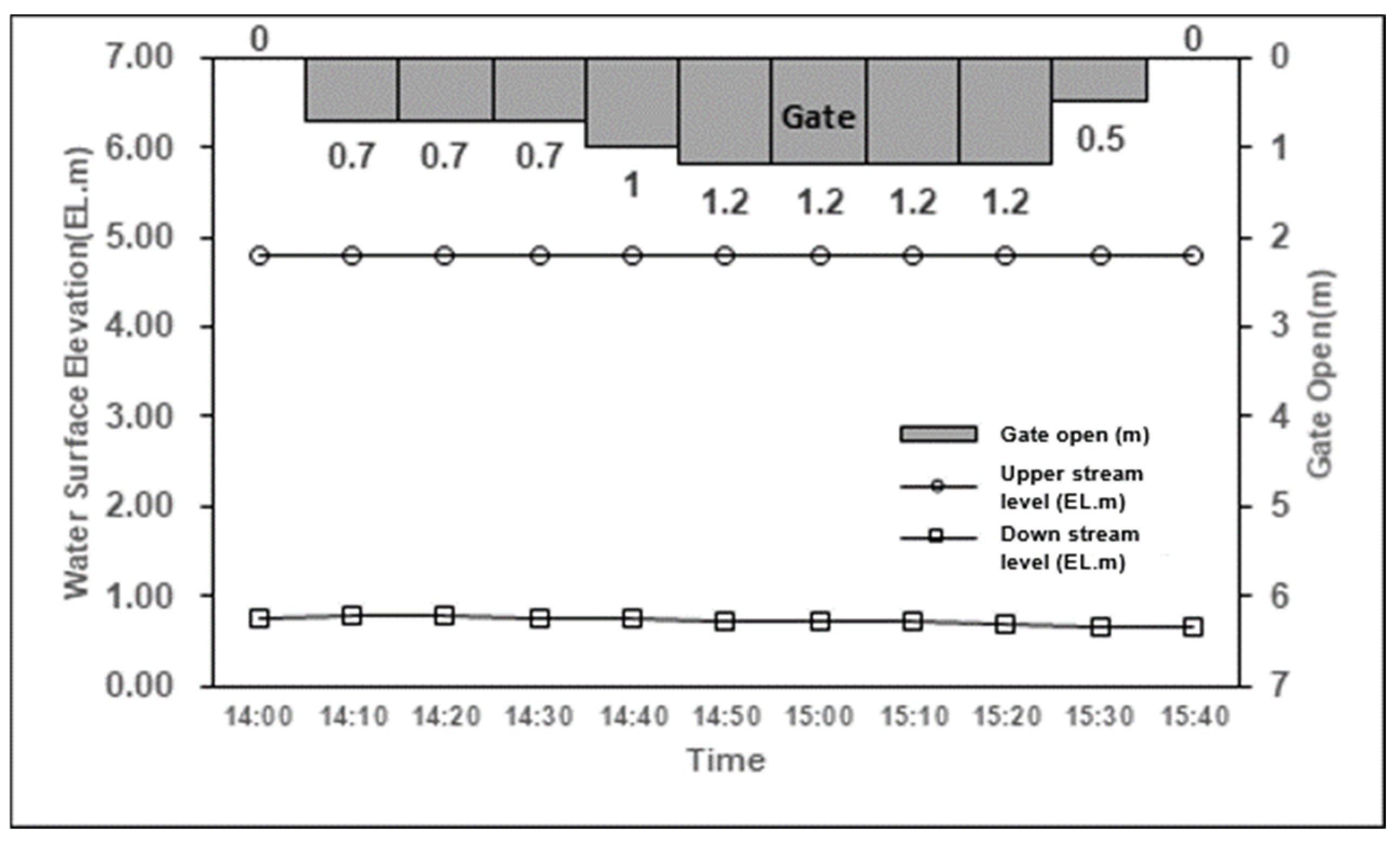
3.3. Field Discharge Experiment
3.4. Calibration of the Model
4. Analysis of 3D Flow Characteristics by Gate Operation Situation
4.1. Review Condition
4.2. Analysis Results
4.2.1. Case 3
4.2.2. Case 4
4.2.3. Case 5
4.2.4. Case 6
4.2.5. Comparison of Analysis Results
4.3. Comparison with Actual Operating Conditions
5. Conclusions
- (1)
- A three-dimensional flow analysis tool that can calculate the flow velocity according to the water depth with the capability to handle rapidly varying flow analysis is essential for high-accuracy research. Therefore, among the commercialized 3D CFD programs, Flow Science Inc.’s FLOW-3D software was used, which has various application cases for domestic rivers, whereas the Changnyeong-Haman weir of the Nakdong River in the ROK was selected as the channel for analysis model construction.
- (2)
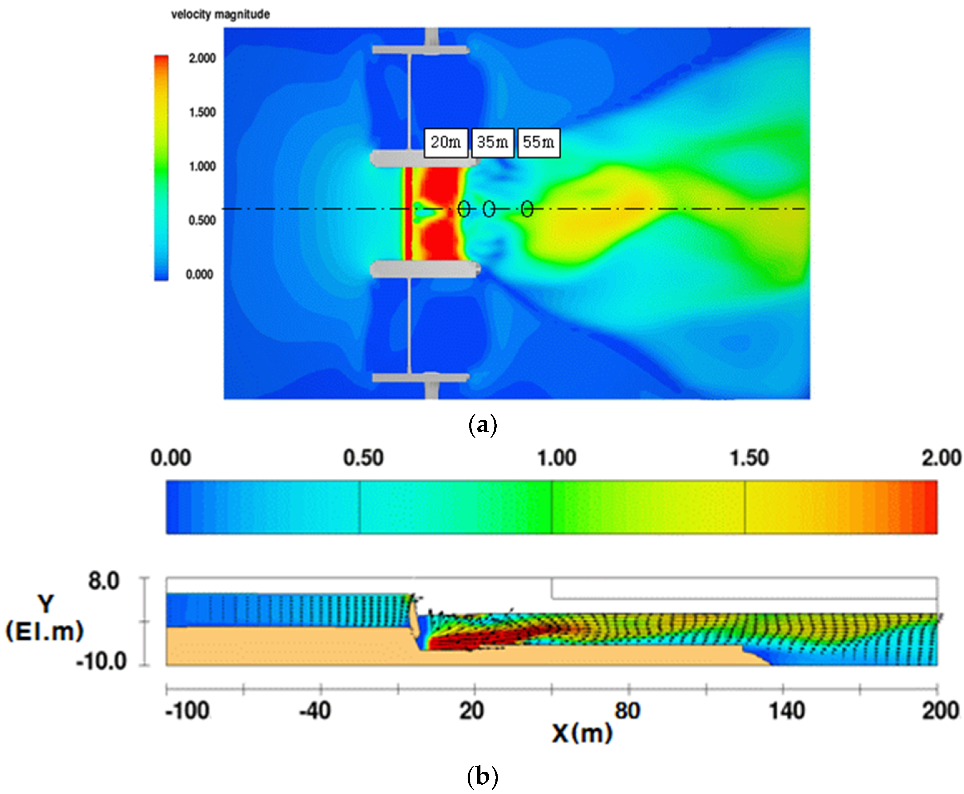
- A 3D flow analysis was performed by applying the same gate operating conditions as in a field gate discharge experiment. In the simulation results, the flow discharge differed from the measured value by 9–15 m3/s, from which the accuracy was evaluated to be 82–87%. The flow velocity was evaluated with an accuracy of 92% from a difference of 0.01 to 0.16 m/s. Accordingly, the suitability of the constructed analysis model was verified.
- (3)
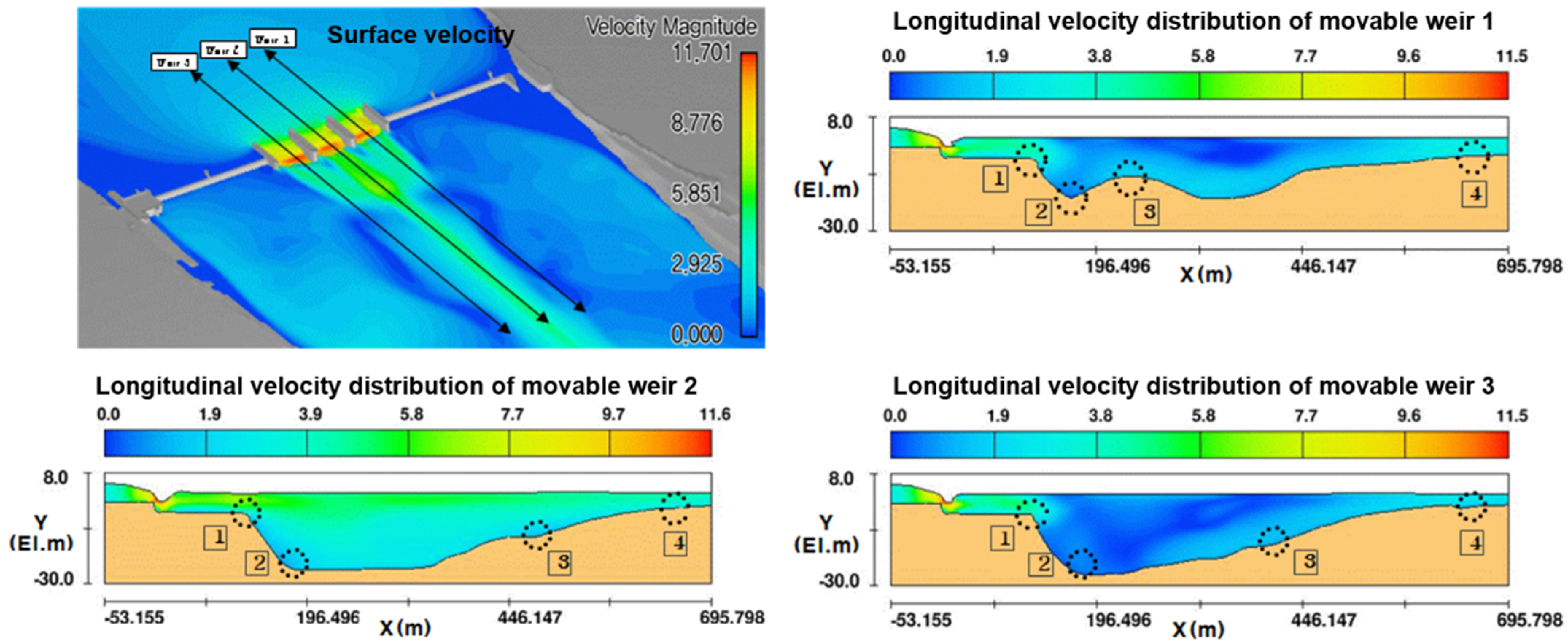
- Based on the verified analysis model, various boundary conditions and gate operating conditions were applied to analyze the flow characteristics downstream of the hydraulic structure, the results of which were compared with the field experiment results. Case 4, where the maximum flow rate occurred in the bed protection section, was analyzed as the worst condition for hydraulic structure design.
- (4)
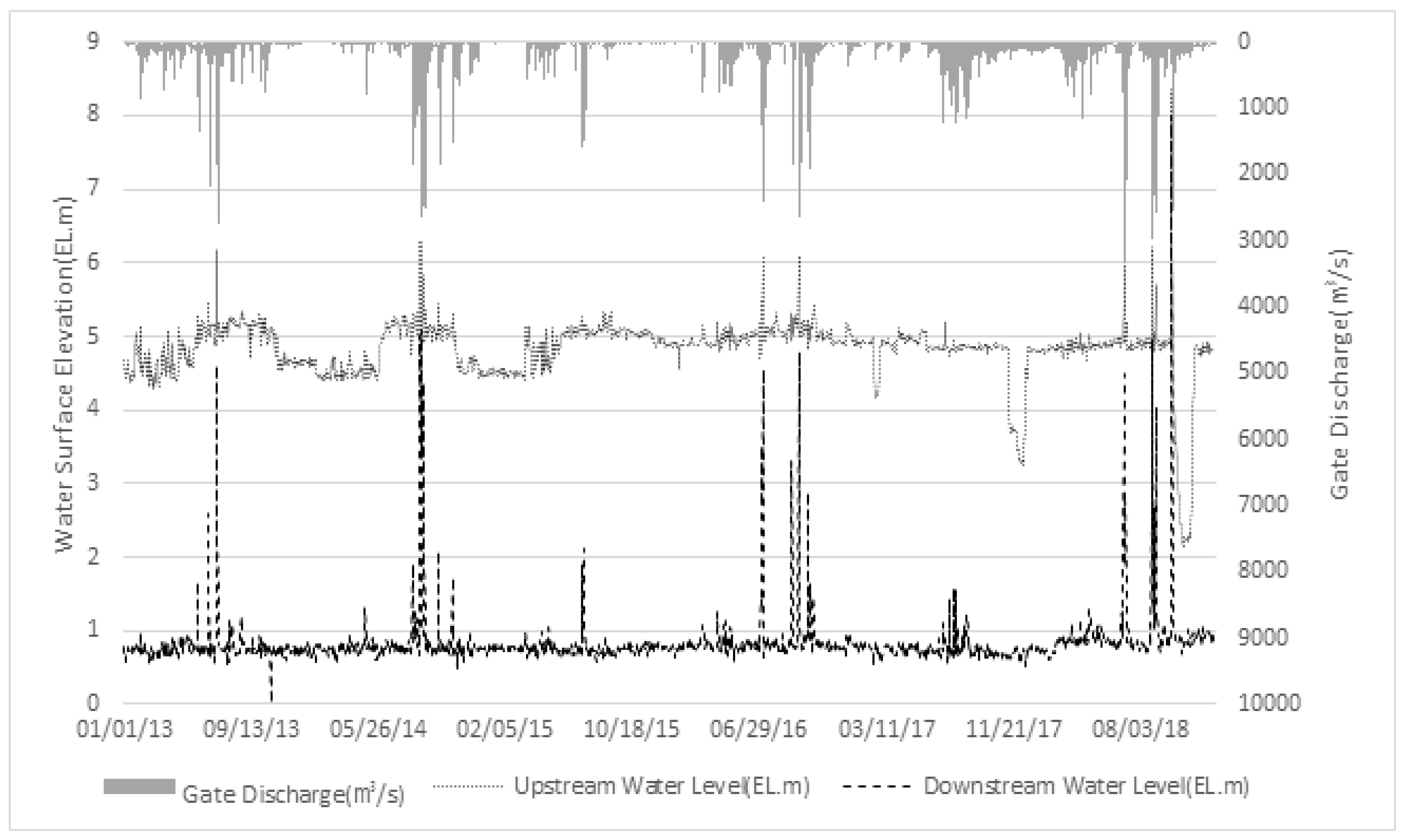
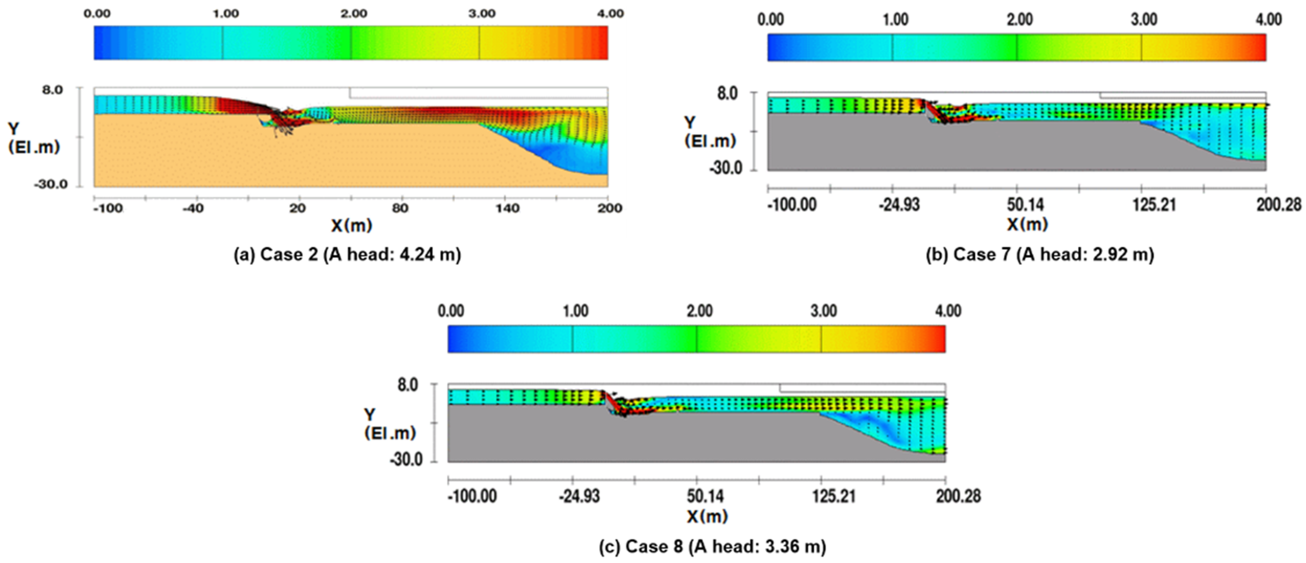
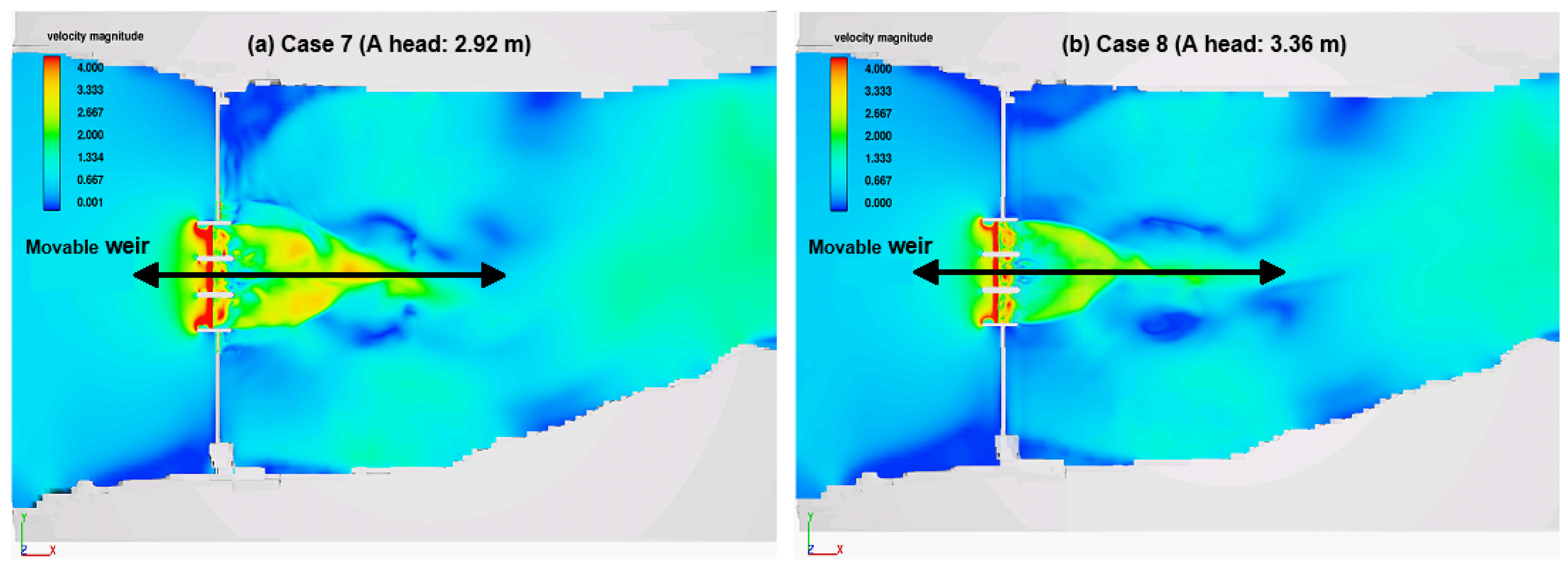
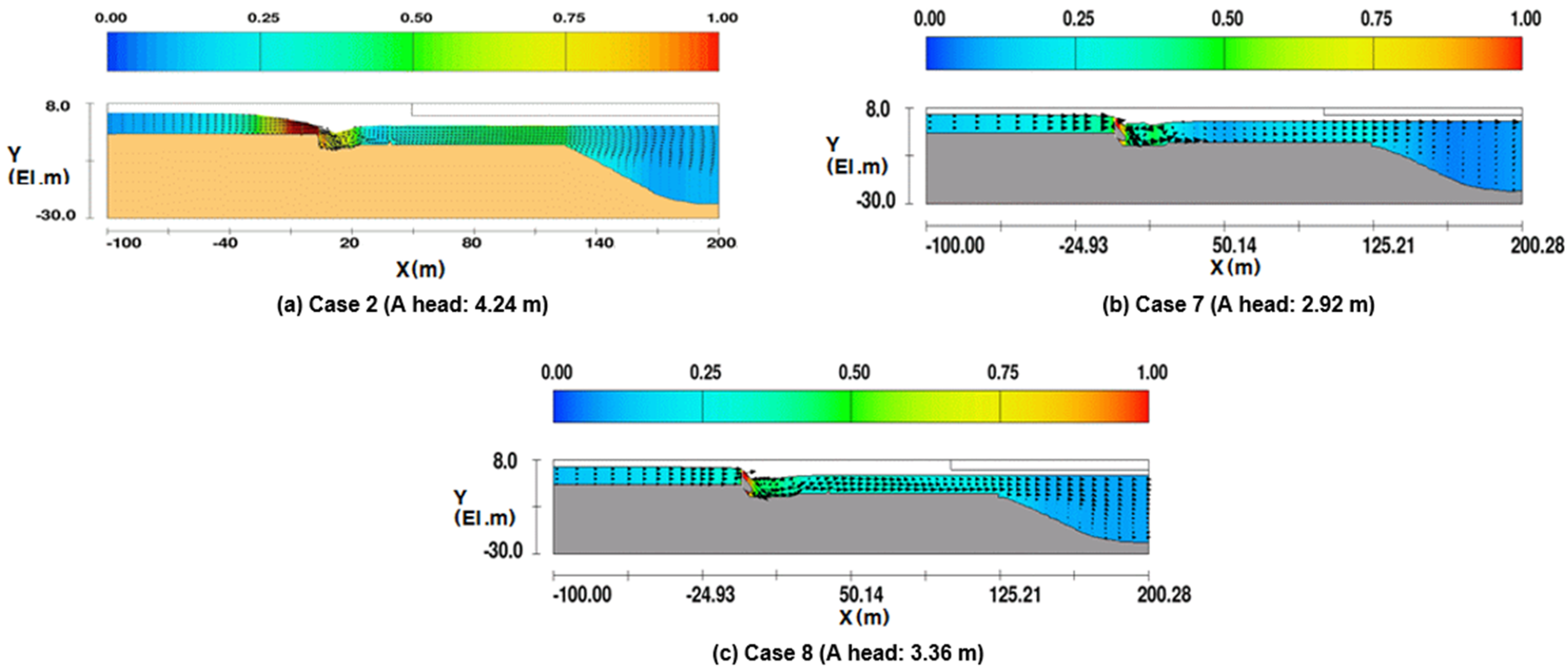
- Finally, by reviewing the gate operation performance of the Changnyeong-Haman weir from 2013 to 2018, two cases in which the sluice gate was opened by more than 50% under a large water level difference were selected, and the flow characteristics were analyzed. As a result of the analysis, the actual operating conditions showed that the velocity and the Froude number were lower than the optimal conditions, confirming that the selected design conditions were appropriate. Additionally, the flow velocity for the apron section was analyzed to be higher as the gate opening was larger. In the bed protection section, it was confirmed that the average flow velocity was high when the water level difference was large, and the bottom velocity was high when the gate opening was large.
Author Contributions
Funding
Institutional Review Board Statement
Informed Consent Statement
Data Availability Statement
Conflicts of Interest
References
- Wanoschek, R.; Hager, W.H. Hydraulic jump in trapezoidal channel. J. Hydraul. Res. 1989, 27, 429–446. [Google Scholar] [CrossRef]
- Bohr, T.; Dimon, P.; Putkaradze, V. Shallow-water approach to the circular hydraulic jump. J. Fluid Mech. 1993, 254, 635–648. [Google Scholar] [CrossRef]
- Chanson, H.; Brattberg, T. Experimental study of the air–water shear flow in a hydraulic jump. Int. J. Multiph. Flow 2000, 26, 583–607. [Google Scholar] [CrossRef]
- Dhamotharan, S.; Gulliver, J.S.; Stefan, H.G. Unsteady one-dimensional settling of suspended sediment. Water Resour. Res. 1981, 17, 1125–1132. [Google Scholar] [CrossRef]
- Ziegler, C.K.; Nisbet, B.S. Long-term simulation of fine-grained sediment transport in large reservoir. J. Hydraul. Eng. 1995, 121, 773–781. [Google Scholar] [CrossRef]
- Olsen, N.R.B. Two-dimensional numerical modelling of flushing processes in water reservoirs. J. Hydraul. Res. 1999, 37, 3–16. [Google Scholar] [CrossRef]
- Saad, N.Y.; Fattouh, E.M. Hydraulic characteristics of flow over weirs with circular openings. Ain Shams Eng. J. 2017, 8, 515–522. [Google Scholar] [CrossRef]
- Bagheri, S.; Kabiri-Samani, A.R. Hydraulic Characteristics of flow over the streamlined weirs. Modares Civ. Eng. J. 2018, 17, 29–42. [Google Scholar]
- Hussain, Z.; Khan, S.; Ullah, A.; Ayaz, M.; Ahmad, I.; Mashwani, W.K.; Chu, Y.-M. Extension of optimal homotopy asymptotic method with use of Daftardar–Jeffery polynomials to Hirota–Satsuma coupled system of Korteweg–de Vries equations. Open Phys. 2020, 18, 916–924. [Google Scholar] [CrossRef]
- Arifeen, S.U.; Haq, S.; Ghafoor, A.; Ullah, A.; Kumam, P.; Chaipanya, P. Numerical solutions of higher order boundary value problems via wavelet approach. Adv. Differ. Equ. 2021, 2021, 347. [Google Scholar] [CrossRef]
- Sharafati, A.; Haghbin, M.; Motta, D.; Yaseen, Z.M. The application of soft computing models and empirical formulations for hydraulic structure scouring depth simulation: A comprehensive review, assessment and possible future research direction. Arch. Comput. Methods Eng. 2021, 28, 423–447. [Google Scholar] [CrossRef]
- Khan, S.; Selim, M.M.; Khan, A.; Ullah, A.; Abdeljawad, T.; Ayaz, M.; Mashwani, W.K. On the analysis of the non-Newtonian fluid flow past a stretching/shrinking permeable surface with heat and mass transfer. Coatings 2021, 11, 566. [Google Scholar] [CrossRef]
- Khan, S.; Selim, M.M.; Gepreel, K.A.; Ullah, A.; Ayaz, M.; Mashwani, W.K.; Khan, E. An analytical investigation of the mixed convective Casson fluid flow past a yawed cylinder with heat transfer analysis. Open Phys. 2021, 19, 341–351. [Google Scholar] [CrossRef]
- Ullah, A.; Selim, M.M.; Abdeljawad, T.; Ayaz, M.; Mlaiki, N.; Ghafoor, A. A Magnetite–Water-Based Nanofluid Three-Dimensional Thin Film Flow on an Inclined Rotating Surface with Non-Linear Thermal Radiations and Couple Stress Effects. Energies 2021, 14, 5531. [Google Scholar] [CrossRef]
- Aamir, M.; Ahmad, Z.; Pandey, M.; Khan, M.A.; Aldrees, A.; Mohamed, A. The Effect of Rough Rigid Apron on Scour Downstream of Sluice Gates. Water 2022, 14, 2223. [Google Scholar] [CrossRef]
- Gharebagh, B.A.; Bazargan, J.; Mohammadi, M. Experimental Investigation of Bed Scour Rate in Flood Conditions. Environ. Water Eng. 2022; in press. [Google Scholar] [CrossRef]
- Laishram, K.; Devi, T.T.; Singh, N.B. Experimental Comparison of Hydraulic Jump Characteristics and Energy Dissipation Between Sluice Gate and Radial Gate. In Innovative Trends in Hydrological and Environmental Systems; Springer: Berlin/Heidelberg, Germany, 2022; pp. 207–218. [Google Scholar]
- Varaki, M.E.; Sedaghati, M.; Sabet, B.S. Effect of apron length on local scour at the downstream of grade control structures with labyrinth planform. Arab. J. Geosci. 2022, 15, 1240. [Google Scholar] [CrossRef]
- Rizk, D.; Ullah, A.; Elattar, S.; Alharbi, K.A.M.; Sohail, M.; Khan, R.; Khan, A.; Mlaiki, N. Impact of the KKL Correlation Model on the Activation of Thermal Energy for the Hybrid Nanofluid (GO+ ZnO+ Water) Flow through Permeable Vertically Rotating Surface. Energies 2022, 15, 2872. [Google Scholar] [CrossRef]
- Kim, K.H.; Choi, G.W.; Jo, J.B. An Experimental Study on the Stream Flow by Discharge Ratio. Korea Water Resour. Assoc. Acad. Conf. 2005, 05b, 377–382. [Google Scholar]
- Lee, D.S.; Yeo, H.G. An Experimental Study for Determination of the Material Diameter of Riprap Bed Protection Structure. Korea Water Resour. Assoc. Acad. Conf. 2005, 05b, 1036–1039. [Google Scholar]
- Choi, G.W.; Byeon, S.J.; Kim, Y.G.; Cho, S.U. The Flow Characteristic Variation by Installing a Movable Weir having Water Drainage Equipment on the Bottom. J. Korean Soc. Hazard Mitig. 2008, 8, 117–122. [Google Scholar]
- Jung, J.G. An Experimental Study for Estimation of Bed Protection Length. J. Korean Wetl. Soc. 2011, 13, 677–686. [Google Scholar]
- Kim, S.H.; Kim, W.; Lee, E.R.; Choi, G.H. Analysis of Hydraulic Effects of Singok Submerged Weir in the Lower Han River. J. Korean Water Resour. Assoc. 2005, 38, 401–413. [Google Scholar] [CrossRef]
- Kim, J.H.; Sim, M.P.; Choi, G.W.; Oh, J.M. Hydraulic Analysis of Air Entrainment by Weir Types. J. Korean Water Resour. Assoc. 2003, 36, 971–984. [Google Scholar] [CrossRef]
- Jeong, S.; Yeo, C.G.; Yun, G.S.; Lee, S.O. Analysis of Characteristics for Bank Scour around Low Dam using 3D Numerical Simulation. Korean Soc. Hazard Mitig. Acad. Conf. 2011, 02a, 102. [Google Scholar]
- Son, A.R.; Kim, B.H.; Moon, B.R.; Han, G.Y. An Analysis of Bed Change Characteristics by Bed Protection Work. J. Korean Soc. Civ. Eng. 2015, 35, 821–834. [Google Scholar]
- French, R.H.; French, R.H. Open-Channel Hydraulics; McGraw-Hill: New York, NY, USA, 1985; ISBN 0070221340. [Google Scholar]






| Division | X Axis (Left, Right) | Y Axis (Flow Direction+) | Z Axis (Vertical Direction) | |||
|---|---|---|---|---|---|---|
| Min | Max | Min | Max | Min | Max | |
| Coordinates | −800 | 600 | −1000 | 1700 | −30 | 18 |
| Division | X Size (m) | Y Size (m) | Z Size (m) | Grid Number | |||
|---|---|---|---|---|---|---|---|
| Min | Max | Min | Max | Min | Max | ||
| Surrounding structure | 0.25 | 0.25 | 0.50 | 0.50 | 0.23 | 0.26 | 153,600 |
| Upstream and downstream sections | 1.25 | 2.69 | 1.00 | 3.90 | 0.33 | 0.38 | 612,000 |
| Other | 2.00 | 12.20 | 4.00 | 9.40 | 0.90 | 1.20 | 775,200 |
| Total | 1,540,800 | ||||||
| Division | Gate Opening | Surface Velocity (m/s) | |||
|---|---|---|---|---|---|
| Review | 20 m Downstream | 35 m Downstream | 55 m Downstream | ||
| Case 1 | 0.7 m (9%) | Min | 1.208 | 0.934 | 0.448 |
| Max | 0.240 | 0.135 | 0.201 | ||
| Average | 0.810 | 0.290 | 0.310 | ||
| Case 2 | 1.2 m (15%) | Min | 0.625 | 1.272 | 1.071 |
| Max | 0.243 | 0.100 | 0.798 | ||
| Average | 0.420 | 0.690 | 0.960 | ||
| Division | Discharge (m3/s) | Surface Velocity (m/s) | ||
|---|---|---|---|---|
| 20 m Downstream | 35 m Downstream | 55 m Downstream | ||
| Field experiment | 50 | 0.81 | 0.29 | 0.31 |
| Numerical analysis | 59 | 0.80 | 0.33 | 0.34 |
| Difference | +9 | −0.01 | +0.04 | +0.03 |
| Accuracy | 82% | 99% | 86% | 90% |
| Division | Discharge (m3/s) | Surface Velocity (m/s) | ||
|---|---|---|---|---|
| 20 m Downstream | 35 m Downstream | 55 m Downstream | ||
| Field experiment | 112 | 0.42 | 0.69 | 0.96 |
| Numerical analysis | 127 | 0.41 | 0.72 | 1.12 |
| Difference | +15 | −0.01 | +0.03 | +0.16 |
| Accuracy | 87% | 98% | 96% | 83% |
| Division | Upstream Level (EL. m) | Downstream Level (EL. m) | Gate Operation | ||
|---|---|---|---|---|---|
| Virtual condition | Managementwater level | Case 3 | 5.00 | 0.76 | Full opening, three gates |
| Case 4 | 5.00 | 0.76 | Full opening, central gate | ||
| 100-year frequency | Case 5 | 12.80 | 12.03 | Full opening, three gates | |
| Case 6 | 12.80 | 12.03 | Full opening, central gate | ||
| Division | Flow Velocity (m/s) | Tractive Force (N/m2) | ||||
|---|---|---|---|---|---|---|
| Weir 1 | Weir 2 | Weir 3 | Weir 1 | Weir 2 | Weir 3 | |
| No. 1 point | 3.98 | 5.14 | 4.81 | 18.47 | 30.95 | 26.89 |
| No. 2 point | 0.84 | 1.86 | 0.60 | 0.57 | 2.57 | 0.26 |
| No. 3 point | 1.81 | 1.98 | 1.53 | 3.10 | 3.52 | 2.02 |
| No. 4 point | 1.73 | 3.58 | 2.35 | 8.32 | 14.97 | 7.26 |
| Division | Flow Velocity (m/s) | Tractive Force (N/m2) |
|---|---|---|
| Weir 2 | Weir 2 | |
| No. 1 point | 5.18 | 26.89 |
| No. 2 point | 1.17 | 0.26 |
| No. 3 point | 2.07 | 2.02 |
| No. 4 point | 1.32 | 7.26 |
| Division | Flow Velocity (m/s) | Tractive Force (N/m2) | ||||
|---|---|---|---|---|---|---|
| Weir 1 | Weir 2 | Weir 3 | Weir 1 | Weir 2 | Weir 3 | |
| No. 1 point | 3.98 | 5.14 | 4.81 | 18.47 | 30.95 | 26.89 |
| No. 2 point | 0.84 | 1.86 | 0.60 | 0.57 | 2.57 | 0.26 |
| No. 3 point | 1.81 | 1.98 | 1.53 | 3.10 | 3.52 | 2.02 |
| No. 4 point | 1.73 | 3.58 | 2.35 | 8.32 | 14.97 | 7.26 |
| Division | Flow Velocity (m/s) | Tractive Force (N/m2) |
|---|---|---|
| Weir 2 | Weir 2 | |
| No. 1 point | 4.36 | 16.07 |
| No. 2 point | 0.16 | 0.02 |
| No. 3 point | 1.66 | 2.06 |
| No. 4 point | 2.01 | 3.44 |
| Division | Weir Gate | Water Level (Upstream, m) | Water Level (Downstream, m) | Velocity (m/s) | Depth (m) | Tractive Force (N/m2) | Propagation Distance (m) |
|---|---|---|---|---|---|---|---|
| Case 3 | #1 | 5.00 | 0.76 | 3.98 | 6.80 | 18.47 | 700 |
| #2 | 5.14 | 6.70 | 30.95 | 700 | |||
| #3 | 4.81 | 6.83 | 26.89 | 700 | |||
| Case 4 | #2 | 5.00 | 0.76 | 5.81 | 6.38 | 40.53 | 200 |
| Case 5 | #1 | 12.80 | 12.03 | 2.13 | 18.07 | 3.83 | 700 |
| #2 | 2.99 | 18.08 | 7.49 | 700 | |||
| #3 | 2.61 | 18.06 | 5.73 | 700 | |||
| Case 6 | #2 | 12.80 | 12.03 | 4.36 | 17.78 | 16.07 | 200 |
| Division | Upstream Water Level (E.L. m) | Downstream Water Level (E.L. m) | Gate Operation | |
|---|---|---|---|---|
| Actual operating conditions | Case 7 | 5.50 | 2.58 | All gates, 54% open |
| Case 8 | 5.14 | 1.78 | All gates, 49% open | |
| Division | Observation Point (m) | |||||||||||||||
| −50 | −40 | −35 | −30 | −25 | −20 | −10 | 0 | 2.9 | 3.9 | 6.2 | 6.9 | 10 | 15 | |||
| Water level (EL. m) | Design | 4.83 | 4.69 | 4.58 | 4.38 | 4.10 | 3.69 | 2.61 | 1.20 | 0.46 | −0.39 | −1.57 | −1.45 | −1.06 | −0.12 | |
| Case 7 | 5.29 | 5.24 | 5.20 | 5.16 | 5.11 | 5.03 | 4.87 | 1.21 | 1.90 | 1.83 | 1.57 | 1.67 | 1.75 | 1.20 | ||
| Case 8 | 4.99 | 4.96 | 4.93 | 4.91 | 4.86 | 4.83 | 4.71 | 0.03 | 0.69 | 0.69 | 0.74 | 0.72 | 0.39 | 0.71 | ||
| Depth (m) | Design | 6.83 | 6.69 | 6.58 | 6.46 | 6.18 | 5.77 | 4.86 | 3.28 | 2.70 | 6.36 | 5.18 | 5.30 | 5.69 | 6.63 | |
| Case 7 | 7.29 | 7.24 | 7.20 | 7.24 | 7.17 | 7.11 | 6.96 | 3.66 | 8.65 | 8.58 | 8.32 | 8.42 | 8.50 | 7.95 | ||
| Case 8 | 6.99 | 6.96 | 6.93 | 6.99 | 6.94 | 6.91 | 6.80 | 2.93 | 7.44 | 7.44 | 7.49 | 7.47 | 7.14 | 7.46 | ||
| Velocity (m/s) | Average | Design | 1.68 | 2.34 | 2.78 | 3.43 | 4.17 | 5.07 | 6.65 | 9.09 | 11.6 | 6.69 | 6.77 | 6.45 | 5.73 | 5.25 |
| Case 7 | 1.98 | 2.23 | 2.42 | 2.55 | 2.81 | 3.02 | 3.30 | 7.50 | 3.79 | 3.58 | 3.33 | 3.30 | 3.44 | 4.04 | ||
| Case 8 | 1.63 | 1.82 | 1.96 | 2.07 | 2.29 | 2.46 | 2.68 | 8.00 | 3.61 | 3.42 | 3.52 | 3.54 | 3.95 | 3.50 | ||
| Bed | Design | 1.06 | 1.57 | 1.97 | 2.57 | 3.25 | 4.37 | 6.22 | 9.09 | 13.2 | 1.03 | 1.80 | 2.70 | 6.60 | 7.90 | |
| Case 7 | 1.52 | 1.72 | 1.92 | 1.96 | 2.21 | 2.42 | 2.20 | 6.36 | 1.06 | 1.89 | 4.36 | 4.87 | 6.42 | 6.32 | ||
| Case 8 | 1.24 | 1.38 | 1.53 | 1.57 | 1.79 | 1.97 | 1.71 | 8.34 | 1.97 | 3.37 | 5.29 | 5.60 | 6.93 | 6.28 | ||
| Froude number | Design | 0.20 | 0.29 | 0.35 | 0.43 | 0.54 | 0.67 | 0.97 | 1.60 | 2.25 | 0.85 | 0.95 | 0.90 | 0.77 | 0.65 | |
| Case 7 | 0.23 | 0.26 | 0.29 | 0.30 | 0.33 | 0.36 | 0.40 | 0.76 | 0.42 | 0.40 | 0.38 | 0.38 | 0.41 | 0.46 | ||
| Case 8 | 0.20 | 0.22 | 0.24 | 0.25 | 0.28 | 0.29 | 0.32 | 0.75 | 0.48 | 0.45 | 0.43 | 0.43 | 0.45 | 0.41 | ||
| Upstream bed protection | Concrete + gate | Downstream apron | ||||||||||||||
| Division | Observation point (m) | |||||||||||||||
| 20 | 25 | 30 | 50 | 60 | 70 | 80 | 90 | 100 | 110 | 120 | 150 | 175 | 200 | |||
| Water level (EL. m) | Design | −0.73 | 0.13 | 0.43 | 0.72 | 0.75 | 0.70 | 0.68 | 0.70 | 0.69 | 0.68 | 0.68 | 0.70 | 0.71 | 0.70 | |
| Case 7 | 1.97 | 2.28 | 2.41 | 2.52 | 2.59 | 2.57 | 2.53 | 2.55 | 2.57 | 2.55 | 2.50 | 2.57 | 2.59 | 2.57 | ||
| Case 8 | 1.18 | 1.42 | 1.62 | 1.74 | 1.79 | 1.82 | 1.79 | 1.74 | 1.72 | 1.72 | 1.72 | 1.73 | 1.79 | 1.80 | ||
| Depth (m) | Design | 6.02 | 5.83 | 6.13 | 6.42 | 6.45 | 6.40 | 6.38 | 6.40 | 6.39 | 6.38 | 6.38 | 15.90 | 24.26 | 26.07 | |
| Case 7 | 8.58 | 7.98 | 8.09 | 8.22 | 8.29 | 8.27 | 8.23 | 8.25 | 8.27 | 8.25 | 8.20 | 17.41 | 25.88 | 27.70 | ||
| Case 8 | 7.79 | 7.17 | 7.32 | 7.44 | 7.49 | 7.52 | 7.49 | 7.44 | 7.42 | 7.42 | 7.42 | 16.98 | 25.22 | 27.07 | ||
| Velocity (m/s) | Average | Design | 4.47 | 2.93 | 1.91 | 2.46 | 2.70 | 3.03 | 3.25 | 3.38 | 3.43 | 3.41 | 3.43 | 1.84 | 1.32 | 1.70 |
| Case 7 | 3.36 | 2.32 | 1.76 | 1.66 | 1.80 | 1.82 | 1.80 | 1.73 | 1.75 | 2.04 | 2.32 | 1.45 | 1.11 | 1.27 | ||
| Case 8 | 2.59 | 1.98 | 1.49 | 1.11 | 1.05 | 1.25 | 1.50 | 1.67 | 1.88 | 2.13 | 2.36 | 1.32 | 1.33 | 1.51 | ||
| Bed | Design | 5.80 | 5.76 | 4.08 | 1.52 | 1.69 | 1.96 | 2.13 | 2.20 | 2.18 | 2.11 | 2.19 | 0.18 | 0.35 | 0.42 | |
| Case 7 | 4.28 | 3.95 | 3.58 | 1.96 | 1.66 | 1.39 | 1.23 | 1.71 | 1.67 | 1.77 | 2.00 | 0.93 | 1.27 | 1.55 | ||
| Case 8 | 4.06 | 3.95 | 2.18 | 1.39 | 1.15 | 1.01 | 0.94 | 0.91 | 1.09 | 1.37 | 1.69 | 1.12 | 1.26 | 2.03 | ||
| Froude number | Design | 0.56 | 0.39 | 0.25 | 0.31 | 0.34 | 0.38 | 0.41 | 0.43 | 0.43 | 0.43 | 0.43 | 0.15 | 0.09 | 0.11 | |
| Case 7 | 0.35 | 0.26 | 0.20 | 0.19 | 0.20 | 0.20 | 0.20 | 0.19 | 0.19 | 0.23 | 0.26 | 0.11 | 0.07 | 0.08 | ||
| Case 8 | 0.37 | 0.35 | 0.32 | 0.32 | 0.33 | 0.33 | 0.29 | 0.28 | 0.27 | 0.27 | 0.27 | 0.10 | 0.10 | 0.10 | ||
| Downstream apron | Downstream bed protection | Stone reinforcement | ||||||||||||||
Publisher’s Note: MDPI stays neutral with regard to jurisdictional claims in published maps and institutional affiliations. |
© 2022 by the authors. Licensee MDPI, Basel, Switzerland. This article is an open access article distributed under the terms and conditions of the Creative Commons Attribution (CC BY) license (https://creativecommons.org/licenses/by/4.0/).
Share and Cite
Kim, B.-J.; Hwang, J.-H.; Kim, B. FLOW-3D Model Development for the Analysis of the Flow Characteristics of Downstream Hydraulic Structures. Sustainability 2022, 14, 10493. https://doi.org/10.3390/su141710493
Kim B-J, Hwang J-H, Kim B. FLOW-3D Model Development for the Analysis of the Flow Characteristics of Downstream Hydraulic Structures. Sustainability. 2022; 14(17):10493. https://doi.org/10.3390/su141710493
Chicago/Turabian StyleKim, Beom-Jin, Jae-Hong Hwang, and Byunghyun Kim. 2022. "FLOW-3D Model Development for the Analysis of the Flow Characteristics of Downstream Hydraulic Structures" Sustainability 14, no. 17: 10493. https://doi.org/10.3390/su141710493
APA StyleKim, B.-J., Hwang, J.-H., & Kim, B. (2022). FLOW-3D Model Development for the Analysis of the Flow Characteristics of Downstream Hydraulic Structures. Sustainability, 14(17), 10493. https://doi.org/10.3390/su141710493


