Capacity Evaluation Method of Ship Terminal Area Based on Network Maximum Flow
Abstract
:1. Introduction
1.1. Capacity Evaluation Methods Based on Mathematical Modeling
1.2. Capacity-Evaluation Methods Based on Historical Data
1.3. Capacity Evaluation Methods Based on Control Load
1.4. The Capacity Evaluation Method Based on Computer Simulation
2. Network Flow Model of Ship Terminal Area
2.1. Problem Description
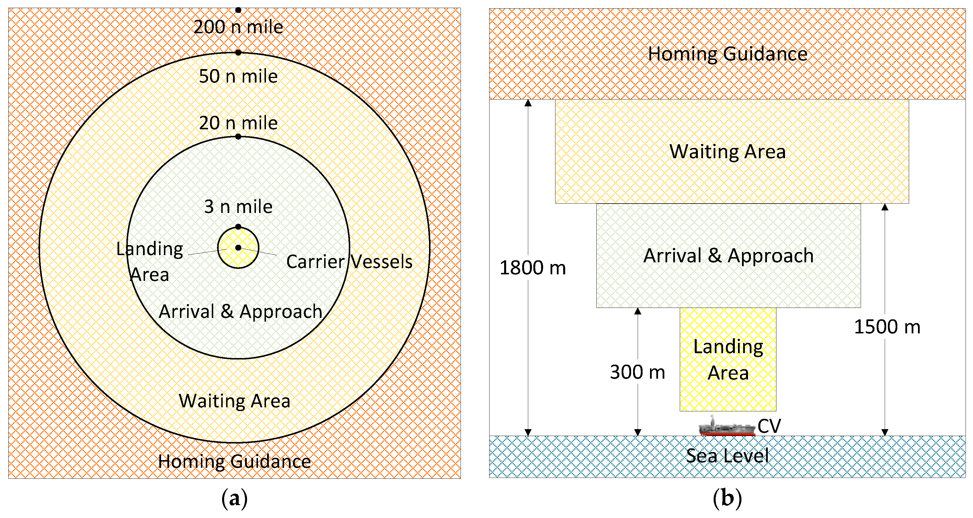
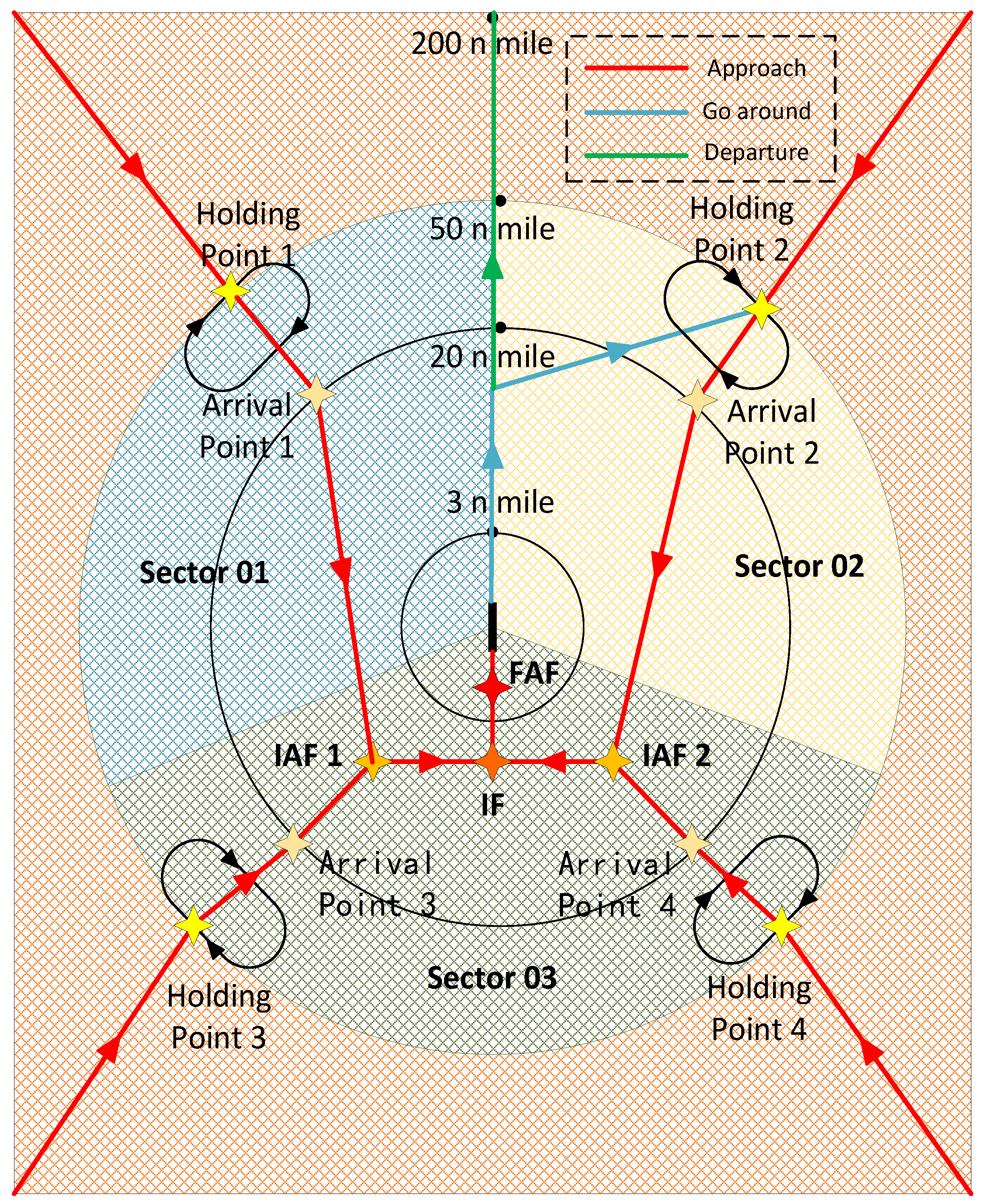
2.2. Airspace Structure Design of the Terminal Area
- For route design, the overall flight time should be as short as possible, and the airspace occupied should be as small as possible.
- In view of the flight characteristics of shipboard aircraft at different stages, the risk of a collision with ships and obstacles is considered to ensure that the shipboard aircraft has sufficient safety during landing.
- Shipboard aircraft routes should not cross multiple aircraft carrier control sectors in a short distance so as to avoid a large load on the aircraft carrier air traffic control center.
- The climb or descent phase of shipboard aircraft routes shall be avoided as far as possible near the boundary of the control sector, thereby avoiding the transfer of control during the climb or descent phase.
2.3. Shipboard Aircraft Arrival and Departure Network Flow
3. Capacity Evaluation Method Based on Network Flow Model
3.1. Assumption Conditions
- The same deck runway is used during the arrival and departure of the shipboard aircraft;
- The length and position of each segment in the arrival and departure route of the shipboard aircraft are known;
- The shipboard aircraft shall fly at a constant speed in each segment;
- A certain safety separation should be maintained between the shipboard aircraft;
- The shipboard aircraft executes a fixed length of holding route.
3.2. Model Establishment
3.2.1. Objective Function
3.2.2. Constraint Conditions
4. Algorithm Solution
| Algorithm 1: Ship terminal capacity calculation method based on simulated annealing |
| Input: Ship terminal network flow capacity matrix , including each segment capacity , deck runway capacity and capacity of gates ; flow constraint matrix . |
| Output: Ship terminal capacity based on SA . |
| Initialization: Set initial annealing temperature, termination annealing temperature , cooling parameter , inner loop length , step size in search , randomly generate decision vector in the capacity matrix range, including each segment flow and relaxation variable . |
| , according to the Formulas (1)–(3), the current network total flow is calculated, and the penalty function and the current objective function that the current flow configuration does not meet the constraints are calculated. |
| while |
| for |
| The random disturbance in decision vector is generated to obtain and calculate the objective function . |
| if |
| , |
| else |
| , Randomly generated real number of intervals [0, 1] |
| if |
| , |
| end |
| end |
| end |
| end |
| After annealing, find the best flow configuration , corresponding ship terminal area capacity |
5. Example Analysis
5.1. Parameter Settings
5.1.1. Ship Parameters
5.1.2. Shipboard Aircraft Parameters
5.1.3. Segment Parameters
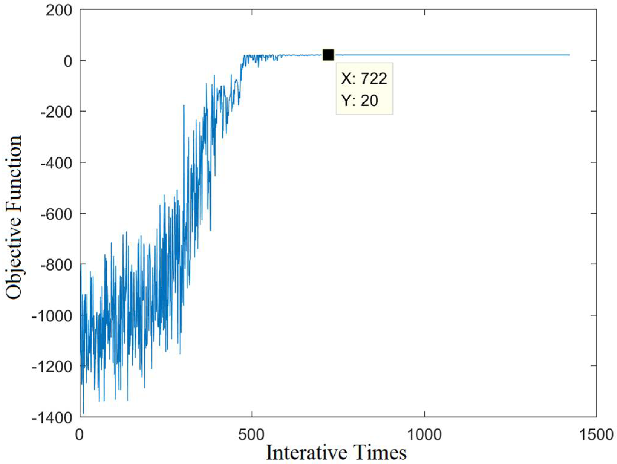
5.2. Result Analysis
5.2.1. Arc Capacity Analysis
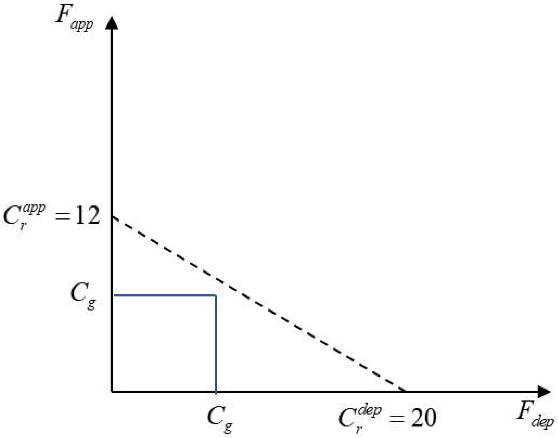
5.2.2. Analysis of Arrival and Departure Capacity
5.2.3. Sensitivity Analysis
- (1)
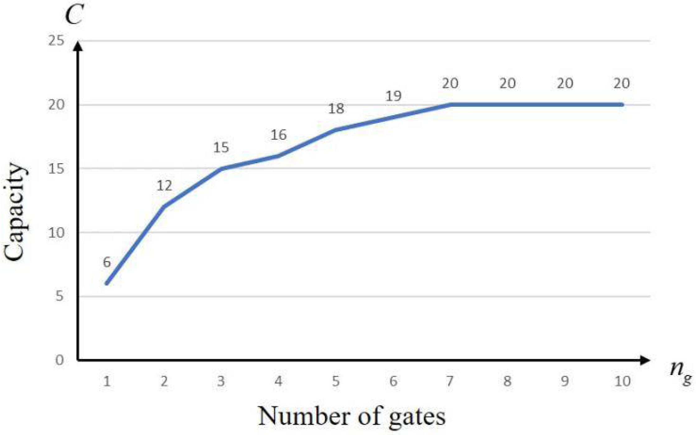
- Number of gates
- (2)
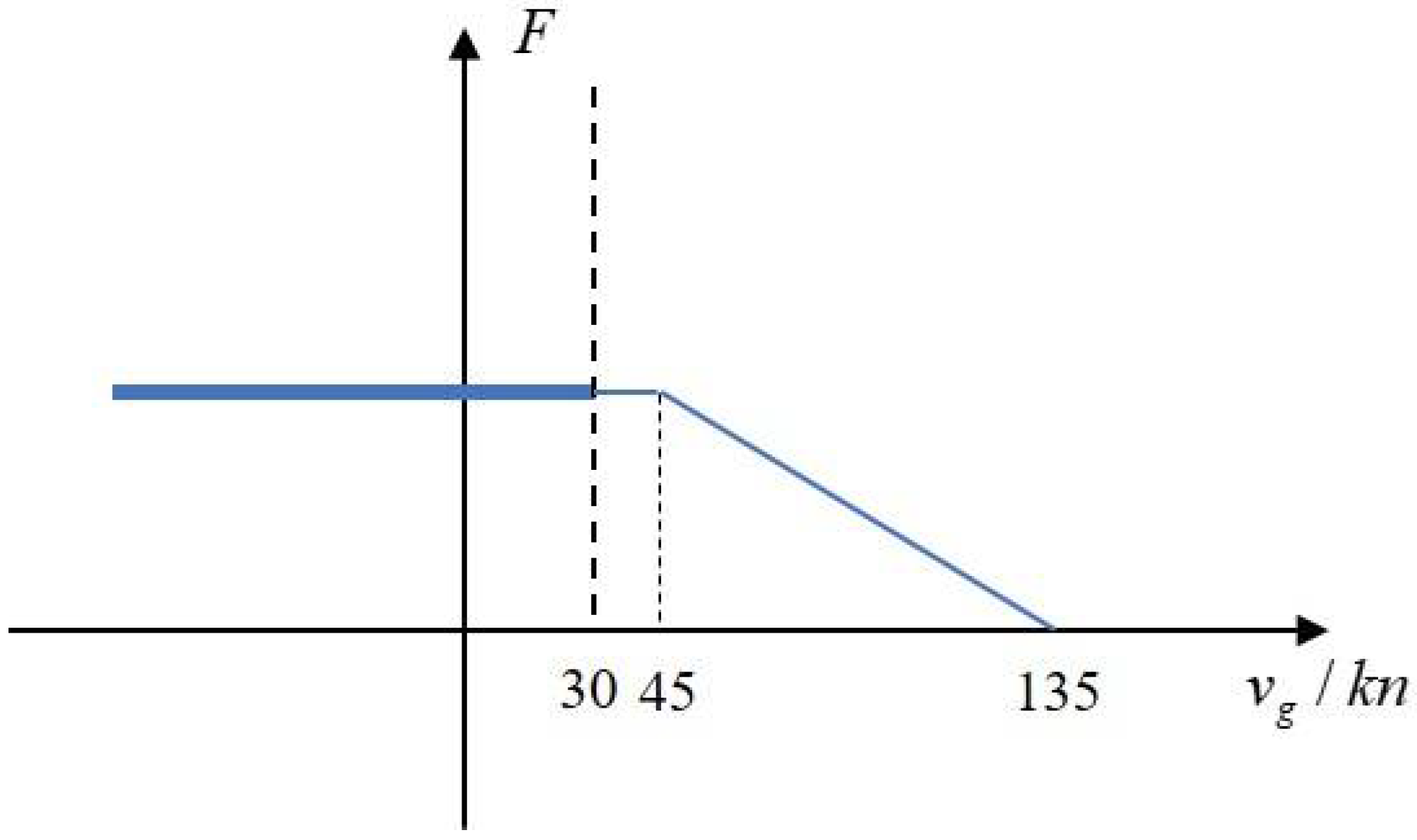
- Ship Moving Speed
6. Conclusions
Author Contributions
Funding
Institutional Review Board Statement
Informed Consent Statement
Data Availability Statement
Conflicts of Interest
References
- Coutard, L.; Chaumette, F.; Pflimlin, J.M. Automatic landing on aircraft carrier by visual servoing. In Proceedings of the IEEE/RSJ International Conference on Intelligent Robots & Systems, San Francisco, CA, USA, 25–30 September 2011. [Google Scholar]
- Schinwald, C.; Pltner, K.O.; Hornung, M. Evaluation of Airport Capacity Optimization Measures. In Proceedings of the AIAA Modeling and Simulation Technologies Conference, Grapevine, TX, USA, 9–13 January 2017. [Google Scholar]
- Bowen, E.; Pearcey, T. Delays in the Flow of Air Traffic. Aeronaut. J. 1948, 52, 251–258. [Google Scholar] [CrossRef]
- Tay, G.; Karpstein, R.; Hornung, M. Airport capacity evaluation of the Air Transportation Network in Selected Global Regions. In Proceedings of the 2018 Aviation Technology, Integration, and Operations Conference, Atlanta, GA, USA, 25–29 June 2018. [Google Scholar]
- Lee, D.A.; Nelson, C.; Shapiro, G. The Aviation System Analysis Capability Airport Capacity and Delay Models; NASA: Washington, WA, USA, 1998.
- Stamatopoulos, M.A.; Zografos, K.G.; Odoni, A.R. A decision support system for airport strategic planning. Transp. Res. Part C Emerg. Technol. 2004, 12, 91–117. [Google Scholar] [CrossRef]
- Mirmohammadsadeghi, N.; Hu, J.; Trani, A. Enhancements to the Runway Capacity Simulation Model Using the ASDE-X Data for Estimating Airports Throughput Under Various Wake Separation Systems. In Proceedings of the AIAA Aviation 2019 Forum, Dallas, TX, USA, 17–21 June 2019. [Google Scholar]
- Tien, S.L.; Taylor, C.; Vargo, E.; Wanke, C. Using Ensemble Weather Forecasts for Predicting Airport Arrival Capacity. In Proceedings of the 16th AIAA Aviation Technology, Integration, and Operations Conference, Washington, WA, USA, 13–17 June 2016. [Google Scholar]
- Callantine, T.J.; Palmer Everett, A. Fast-time simulation studies of terminal-area spacing and merging concepts. In Proceedings of the Digital Avionics Systems Conference, Indianapolis, IN, USA, 12–16 October 2003; San Jose State University: San Jose, CA, USA; NASA Ames Research Center: Mountain View, CA, USA, 2003. [Google Scholar]
- Tian, Y.; Yang, S.S.; Wan, L.L.; Yang, Y. Research on the method of sector dynamic capacity evaluation. Syst. Eng. -Theory Pract. 2014, 34, 2163–2169. [Google Scholar]
- Liu, L. Terminal Airspace Capacity Evaluation Model under Weather Condition from Perspective of a Controller. Int. J. Aerosp. Eng. 2018, 2018, 1–11. [Google Scholar] [CrossRef] [PubMed]
- Schinwald, C.; Pltner, K.O.; Hornung, M. Using Airport Fast-Time Simulation Models to Increase the Quality of Airport Capacity Utilization Studies. In Proceedings of the AIAA Modeling and Simulation Technologies Conference, Washington, DC, USA, 13–17 June 2016. [Google Scholar]
- Sood, N.; Wieland, F. Total airport and airspace model (TAAM) parallelization combining sequential and parallel algorithms for performance enhancement. In Proceedings of the 2003 Winter Simulation Conference, New Orleans, LA, USA, 7–10 December 2003. [Google Scholar]
- Urnes, J.; Hess, R.; Moomaw, R.; Huff, R. Development of the Navy H-Dot Automatic Carrier Landing System designed to give improved approach control in air turbulence. In Proceedings of the Guidance and Control Conference (AIAA), Boulder, CO, USA, 6–8 August 1979. [Google Scholar]
- Shafer, D.M.; Paul, R.C.; King, M.J.; Denham, J.W. Aircraft Carrier Landing Demonstration using Manual Control by a Ship-based Observer. In Proceedings of the AIAA Scitech 2019 Forum, San Diego, CA, USA, 7–11 January 2019. [Google Scholar]
- Bardera-Mora, R.; Garcia-Magarino, A.; Rodriguez-Sevillano, A.; Barcala-Montejano, M.A. Aerodynamic Flow Effects on Aircraft Carrier Takeoff Performance. J. Aircr. 2019, 56, 1005–1013. [Google Scholar] [CrossRef]
- Xia, G.; Dong, R.; Xu, J.; Zhu, Q. Linearized Model of shipboard aircraft Dynamics in Final-Approach Air Condition. J. Aircr. 2015, 53, 1–15. [Google Scholar]
- Ishimatsu, T.; Weck, O.D.; Hoffman, J.; Ohkami, Y.; Shishko, R. A Generalized Multi-Commodity Network Flow Model for Space Exploration Logistics. In Proceedings of the AIAA SPACE 2013 Conference and Exposition, San Diego, CA, USA, 10–12 September 2013. [Google Scholar]
- Mohammadi, M.; Hofman, W.; Tan, Y. Simulated Annealing-based Ontology Matching. ACM Trans. Manag. Inf. Syst. (TMIS) 2019, 10, 1–24. [Google Scholar] [CrossRef]


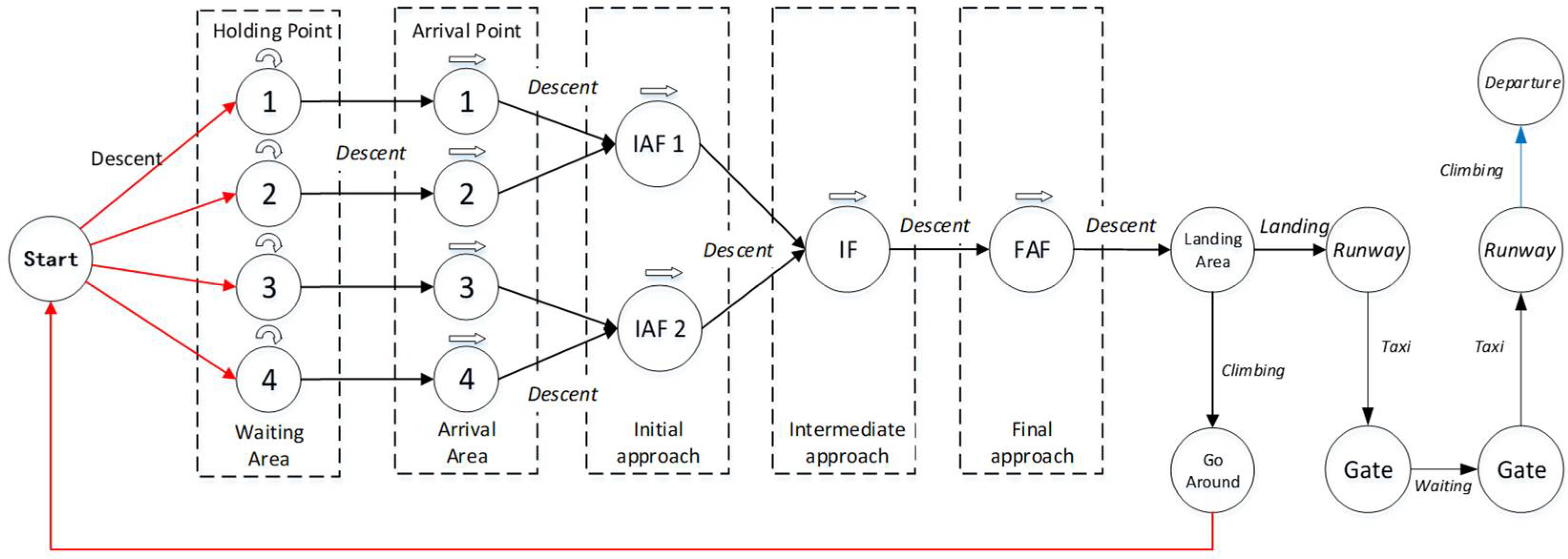
| Name | Meaning |
|---|---|
| Starting point | |
| Intermediate approach point | |
| Final approach point | |
| Missed approach point | |
| Ship landing area | |
| Ship runway | |
| Gates | |
| Departure point |
| Parameter | Number | Unit |
|---|---|---|
| Length of deck runway | 260 | m |
| Number of gates | 13 | / |
| Average maintenance time | 20 | min |
| Maximum speed | 30 | kn |
| Average landing time | 5 | min |
| Average take-off time | 3 | min |
| Parameter | Number | Unit |
|---|---|---|
| Take-off airspeed | 130 | kn |
| Final approach average airspeed | 140 | kn |
| Intermediate approach average airspeed | 140 | kn |
| Average initial approaching airspeed | 250 | kn |
| Average arrival airspeed | 250 | kn |
| Longitudinal safety separation | 5 | n mile |
| Parameter | Number | Unit |
|---|---|---|
| Length of descending segment | 150 | n mile |
| Average altitude of descending segment | 10,000 | ft |
| Length of holding segment | 8 | n mile |
| Average altitude of holding segment | 6000 | ft |
| Length of arrival segment | 30 | n mile |
| Average altitude of arrival segment | 6000 | ft |
| Length of initial approach segment | 7.5 | n mile |
| Average altitude of starting segment | 3100 | ft |
| Length of intermediate approach segment | 9.5 | n mile |
| Average altitude of intermediate segment | 1200 | ft |
| Length of last approach | 3 | n mile |
| Average altitude of final segment | 600 | ft |
| Length of departure segment | ∞ | n mile |
| Segment | Arc Capacity (Number) |
|---|---|
| Descending segment | 89 |
| Arrival segment | 53 |
| Initial approach segment | 48 |
| Intermediate approach segment | 31 |
| Final approach section | 27 |
| Missed approach segment | 45 |
| The deck runway (landing) | 12 |
| Gates | 39 |
| Deck runway (takeoff) | 20 |
| Departure segment | ∞ |
Publisher’s Note: MDPI stays neutral with regard to jurisdictional claims in published maps and institutional affiliations. |
© 2022 by the authors. Licensee MDPI, Basel, Switzerland. This article is an open access article distributed under the terms and conditions of the Creative Commons Attribution (CC BY) license (https://creativecommons.org/licenses/by/4.0/).
Share and Cite
Zhong, G.; Fei, Y.; Yi, J.; Feng, D.; Feng, O. Capacity Evaluation Method of Ship Terminal Area Based on Network Maximum Flow. Sustainability 2022, 14, 10470. https://doi.org/10.3390/su141710470
Zhong G, Fei Y, Yi J, Feng D, Feng O. Capacity Evaluation Method of Ship Terminal Area Based on Network Maximum Flow. Sustainability. 2022; 14(17):10470. https://doi.org/10.3390/su141710470
Chicago/Turabian StyleZhong, Gang, Yuhan Fei, Jia Yi, Dikun Feng, and Ouge Feng. 2022. "Capacity Evaluation Method of Ship Terminal Area Based on Network Maximum Flow" Sustainability 14, no. 17: 10470. https://doi.org/10.3390/su141710470
APA StyleZhong, G., Fei, Y., Yi, J., Feng, D., & Feng, O. (2022). Capacity Evaluation Method of Ship Terminal Area Based on Network Maximum Flow. Sustainability, 14(17), 10470. https://doi.org/10.3390/su141710470


