Article

Numerical Simulation of Fracture Propagation during Refracturing

1
School of Mechanical Engineering, Beijing Institute of Petrochemical Technology, Beijing 102617, China
2
John and Willie Leone Family Department of Energy and Mineral Engineering, The Pennsylvania State University, University Park, PA 16802, USA
3
Fracturing and Acidizing Technical Center, CNPC Research Institute of Petroleum Exploration & Development, Beijing 100083, China
*
Authors to whom correspondence should be addressed.
Sustainability 2022, 14(15), 9422; https://doi.org/10.3390/su14159422
Submission received: 1 June 2022 / Revised: 15 July 2022 / Accepted: 29 July 2022 / Published: 1 August 2022
(This article belongs to the Special Issue Numerical Analysis of Rock Mechanics and Crack Propagation)

Abstract

:
Hydraulic fracturing is repeated in some unconventional wells after production since the initial fracturing treatment. Due to prior production, the stress field around the existing fractures possibly rotates, and this impacts the refracturing operation. In this study, an extended finite element model (XFEM) including junction enrichments of intersecting fractures was proposed to simulate fracture propagation during refracturing in the cemented fractured reservoirs. In the XFEM model, a lubrication equation coupling both tangential and normal flow in hydraulic fractures (HFs) was used to describe the fluid flow behavior within the fractured elements, and the Newton-Raphson method was used to solve the nonlinear fluid–solid coupling system of the refracturing model. The effects of approaching angle, stress anisotropy, and production time were discussed. The results showed that the effects of these factors on improvement of fracture complexity during refracturing depend on the reservoir parameters and the stress field. The characteristics of the injection pressure curves during refracturing were analyzed.

1. Introduction

Hydraulic fracturing is a technology to enhance the recovery of unconventional resources such as tight sandstone oil and gas, shale gas, coalbed methane (CBM), and natural gas hydrate, most of which are stored in the naturally fractured formations [1,2,3]. In the process of hydraulic fracturing operation, large volumes of viscous fracturing fluids and proppant are pumped into the formation to create high conductivity channels for hydrocarbon production [4,5,6]. In the homogeneous formation, double-wing fractures are created. Nevertheless, the pre-existing weak planes such as cemented natural fractures (NFs) or joints affect the HF geometry, possibly due to their mechanical interaction [7,8,9]. Microseismic monitoring, transient pressure analysis, and laboratory core study show that complex fracture network patterns can be generated in hydraulic fracturing in fractured formations. Field application in Barnett shale showed that the production of wells is related to the HF complexity [10]. Therefore, it is feasible to increase the production in fractured wells by improving the HF complexity.
In past decades, various fracturing operations, such as pumping hesitation [11,12], diverter injection [13], and slickwater fracturing at a high injection rate [14], have been performed in tight low-permeability reservoirs. Among these operations, refracturing, which creates a secondary HF due to production-driven stress reorientation around original HFs, is feasible to enhance the HF complexity [1,15]. It has been verified in field tests and reservoir modeling that refracturing increases the production significantly [1,16,17]. The varying stress field around the original HF is contributed to the combined poroelastic and mechanical effects [18,19,20]. The production following the original fracturing treatment creates a significant pore pressure gradient near the wellbore, i.e., a pore pressure depletion zone [1,19]. This depletion leads to the variation in the value and orientation of stress, which affects the fracture re-initiation direction in refracturing. Therefore, the created secondary fracture can penetrate the un-stimulated zone deeply and enlarge the drainage area.
The fracture reorientation was verified in laboratory tests [21]. The experiments showed that HF initiation and propagation are influenced by the magnitude and direction of the pore pressure gradient. The HF is more likely to propagate into the regions with higher local pore pressure. Nevertheless, Berchenko and Detournay [22] suggested that the change in stress induced by pore fluid diffusion leads to variation in the fracture tip stress intensity factor during the injection and affects the HF growth velocity and propagation direction.
Theoretical analysis and numerical modeling have been carried out to understand the mechanism of fracture reorientation during refracturing. Based on the analytic solution of the induced stress field in a homogeneous domain with an infinitely long 2D fracture [18], Warpinski and Branagan proposed the concept of altered-stress fracturing [15]. They argued that the stress reversal occurs if σh + σx is higher than σH + σz, where σH and σh denote the original maximum and minimum horizontal principal stress, respectively, and σx and σz denote the induced stress in the σh and σH directions, respectively. The hydro-mechanical coupling effect is the most important factor affecting stress reorientation before refracturing. The stress reorientation occurs when fluids flow out of the poroelastic media during production of wells, which causes depletion in pore pressure and rock deformation, finally creating the induced stress field. Palmer [1] suggested that both high pressure and confined fracture height are beneficial for stress reversal in the CBM wells. Elbel and Mack [19] proposed the theory of fracture reorientation in refracturing. Numerical simulation shows that there is an optimum time window of the refracturing operation, which depends on the reservoir properties and the production of wells. A long original fracture helps create a fracture with the maximum penetration into the un-stimulated region when fracture reorientation occurs. The fracture perpendicular to the original fracture is beneficial to following production of wells as the new fracture can propagate into the undrained area with the lower pressure depletion. Once the secondary fracture propagates beyond the isotropic point, the new fracture can be diverted to the original σH direction, as illustrated in Figure 1 [16].
The azimuth and length of the secondary fracture (i.e., refracture) during refracturing are affected by pay zone thickness, horizontal permeability anisotropy, horizontal stress anisotropy, shear modulus contrast between pay zone and the bounding layers, production rate, etc., [16,20,23,24]. Numerical simulation shows that the refracturing effect is improved in the reservoir with a larger thickness, smaller stress anisotropy, a weaker boundary layer, and a larger degree of pressure depletion. Dimensionless time, dimensionless stress deviator, and dimensionless toughness are the main controlling factors in the refracturing process [16].
It has been shown in the field measurement that the angle between the new fracture and the original HF in five refractured wells is between 30°–60°, and the angle is larger than 60° in the infill wells [25,26]. Based on the field observations, Wang et al. [27] established a refracturing model that considers initiation angles respect to the original hydraulic fracture. Chen et al. [28] established a refracturing model in a conglomerate reservoir, which considers the temporary plugging effect during the refracturing process. In the naturally fractured reservoirs, HF propagation is complicated, and the multi-strand fracture network tends to be formed due to NFs or joints [7,8,11]. Nevertheless, these cemented NFs are not considered as the weak plane in hydraulic fracturing. Dahi-Taleghani [7] presented the fracture kink path, a refracture extension path, as a possible bifurcation mechanism in fracturing. In other words, the initiation point of the new HF should be only at fracture tips in the reservoirs which have been hydraulically fractured. According to mechanics, the stress singularity occurs in these kink points and only follows that at the tips of the major HF. Hence, the fractures can be re-initiated in these kink points during refracturing.
Based on mechanical analysis of fracture re-initiation, the XFEM leveraged by the cohesive zone method (CZM) was used to study the complex fracture configuration during refracturing in the fractured reservoirs. The CZM model is superior to the linear elastic fracture mechanics (LEFM) model when considering the interactions between fractures. Our results give new insights into the mechanism of improving fracture complexity during refracturing.

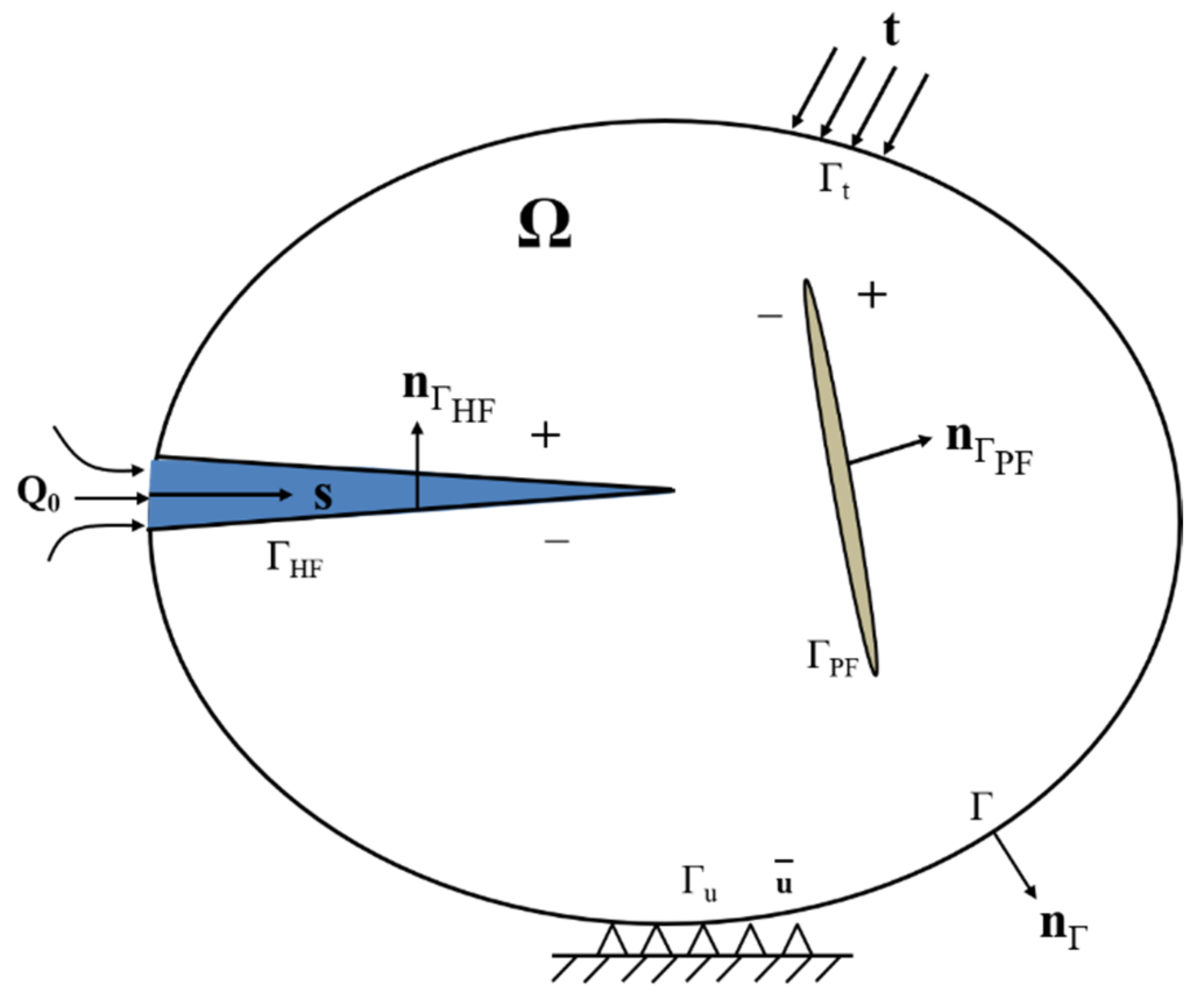
2. Method and Theory

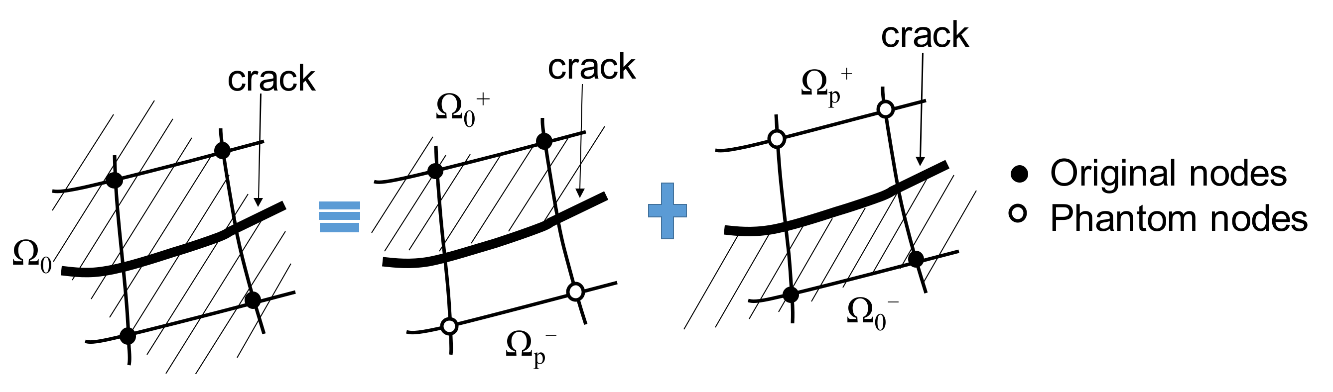
2.1. Enrichment Displacement Functions

In numerical simulation of stationary fracture with the standard finite element method, the generated mesh is conformed to the discontinuities of the displacement field due to the stress singularity near fracture tips. There is a large difficulty in creating a conforming mesh, and modeling of propagating HF requires an enormous amount of computation. The large amount of computation is because the mesh must be updated at each time step to match the geometric discontinuity as the HF propagates.
Through the partition of unity method [29], the XFEM, which was introduced by Belytschko and Black [30], is a useful technique to avoid using a conforming mesh. In XFEM, enrichment functions are integrated into a conventional displacement approximation which presents the discontinuity. Thus, XFEM does not require sufficient mesh refinement near the fracture tip. The enrichment displacement is expressed as
u = I = 1 N N I ( x ) [ u I + H ( x ) a I + α = 1 4 F α ( x ) b I α ]
where NI(x) are the standard basis functions; uI is the standard displacement field; aI is the nodal enriched degree of the freedom (DoF) vector where the basis function support is intersected by the fracture interior; b I α is the enriched DoF vector where the basis function support is cut by the crack tip; H(x) is the associated discontinuous step function across the fracture surface and is expressed as
H ( x ) = 1 ( x x * ) · n 0 1 otherwise
where x is a material point, x* is the crack point closest to x, and n is the unit normal vector to point outward to the crack surface at x*.
The associated elastic asymptotic fracture-tip function Fα(x) is expressed as
F α ( x ) = [ r sin θ 2 , r cos θ 2 , r sin θ sin θ 2 , r sin θ cos θ 2 ]
where (r,θ) is in polar coordinates with the origin at the fracture tip, and θ = 0° is tangent to the fracture tip. Nevertheless, the fracture singularity is dependent on the fracture location within the formation, and thus, capturing of the singularity near fracture tips requires continuous tracking of HF propagation, which leads to an enormous amount of computation. Therefore, the asymptotic singularity functions of HFs are not incorporated into ABAQUS Standard solver [31].
As shown in Figure 2, the phantom node method is used to describe the displacement jump of the fractured zones [32], and these nodes are superimposed with the original nodes.

2.2. Fluid Flow within HFs

To simulate the fluid flow within HFs, the pore pressure nodes are integrated into a fractured element, as illustrated in Figure 3. We presumed that the fluids inside the HFs are incompressible, and the fluid flow that is both tangential and normal to crack surfaces can occur within and across the fractured elements [33,34].
By using Darcy’s law, the tangential flow behavior is expressed as
q d = k t p
k t = d 3 12 μ
where q is the flow rate, kt is the tangential permeability along with HFs, and p is the pressure gradient along with HFs.
The normal flow across the fractured elements is defined as
q L = c L ( p i p L )
where qL is the leak-off rate; cL is the leak-off coefficient; pi and pL are the pressure within HFs and on the fracture surfaces, respectively.
According to linear poroelasticity in rocks, the constitutive equation between stress and strain in a rock matrix is defined as [35]:
σ i j σ i j 0 = E 1 + υ ε i j + υ 1 2 υ ε k k δ i j α p w p w 0 δ i j
where υ is Poisson’s ratio; σij and σ i j 0 are the Cauthy stress and original stress tensor, respectively; E is elastic modulus; pw and p w 0 are the pressure in the rock matrix and the original formation pressure, respectively; εij and εkk are the strain tensor and the volume strain, respectively; α is the Biot constant between 0–1; and δij is the Kronecker delta symbol.

2.3. Traction–Separation Constitutive Behavior

In ABAQUS, traction–separation cohesive behavior is integrated into the framework of XFEM, which was proposed by Barenblatt [36]. XFEM-based CZM is useful in modeling brittle and ductile fracture propagation. This method does not require a preset path such as cohesive elements. The fracture can freely extend independent of the mesh. Therefore, XFEM-based CZM provides a powerful technique for simulating non-planar fracture propagation. As shown in Figure 4, the elastic behavior is expressed as [36]:
t = t n t s = K n n 0 0 K s s δ n δ s = K δ
where t is the nominal traction vector with two components of tn and ts; δ is the separation vector with two components of δn and δs; K is the cohesive stiffness matrix with non-zero diagonal elements of Knn and Kss.
The maximum principal stress criterion is adopted to predict the fracture initiation direction, which is expressed as:
f = σ max σ max 0
where σ m a x 0 is the maximum principal stress; and the symbol <> is the Macaulay bracket, which indicates that damage cannot occur under a purely compressive stress state. It was assumed the damage occurs in rocks when the maximum principal stress ratio reaches the critical value of 1.
The nominal stress components, i.e., tn and ts, are, respectively, written as:
t n = ( 1 D ) T n , T n 0 T n , otherwise
t s = ( 1 D ) T s
where D is the damage factor between 0–1; Tn and Ts are normal and shear stress components without damage, respectively. To describe the damage evolution across the fracture, an effective separation δm is written as:
δ m = δ n 2 + δ s 2
To model the mixed-mode failure behavior, the BK law is expressed as [37]:
G e q u i v C = G I C + ( G I I C G I C ) ( G I I G I + G I I ) η
G e q u i v = G I + G I I
where Gequiv and GequivC are the equivalent and critical fracture energy release rate, respectively; GI and GII are the fracture energy release rate in the normal and shear directions, respectively; GIC and GIIC are the critical fracture energy release rate in the normal and shear directions, respectively; η is the power exponent constant. This model presents a power-law relationship that combines mixed-mode energy release rates with fracture criterion.

3. Numerical Simulation

The physical model of refracturing is shown in Figure 5, and a semi-symmetric finite element model was adopted to reduce the computational expense. The injection location was at the midpoint of the left boundary in the computational domain. Four steps were included in the whole computation process: (i). the geostatic equilibrium of the original in situ stress; (ii). the first fracturing; (iii). the post-frac production; and (iv). the refracturing. An original fracture is normal to the left edge from the injection point. An HF (denoted as ΓHF in Figure 5) propagates along the original fracture when the injected fluids flow into the wellbore in the first fracturing step. Then, the fractured wells are produced for some time, and the pore pressure depletion zone occurs due to the poroelastic effect. Meanwhile, the stress field is reorientated near the HF in the first fracturing. In the refracturing process, the HF interacts with a pre-existing fracture (PF) of different approaching angles (denoted as ΓPF) in the domain. The HF is re-initiated from the tips of pre-existing fractures (PFs) and propagates and diverts along a certain direction due to the production-induced stress field.
All the parameters of the refracturing model are given in Table 1. It was assumed that the fracturing fluid is in-compressible with a constant viscosity of 1 mPa·s, the leak-off coefficient across the HF is 5.879 × 10⁻¹³ Pa/(m·s), and the first fracturing and refracturing steps last for 100 s and 86,400 s at the rate of 2 × 10⁻³ m2/s and 2 × 10⁻⁴ m2/s, respectively. A total of 1089 quadrilateral pore pressure elements (CPE4P) were generated in the computational domain. The keyword “propagation mode = merging” was added to the ABAQUS input file to simulate the fracture re-initiation and propagation. It is worth noting that the flow rate Qinj was positive in the production step and is negative in the first fracturing and refracturing steps. A constant pore pressure and the roller displacement boundary conditions were set on the outer boundary in Figure 5.

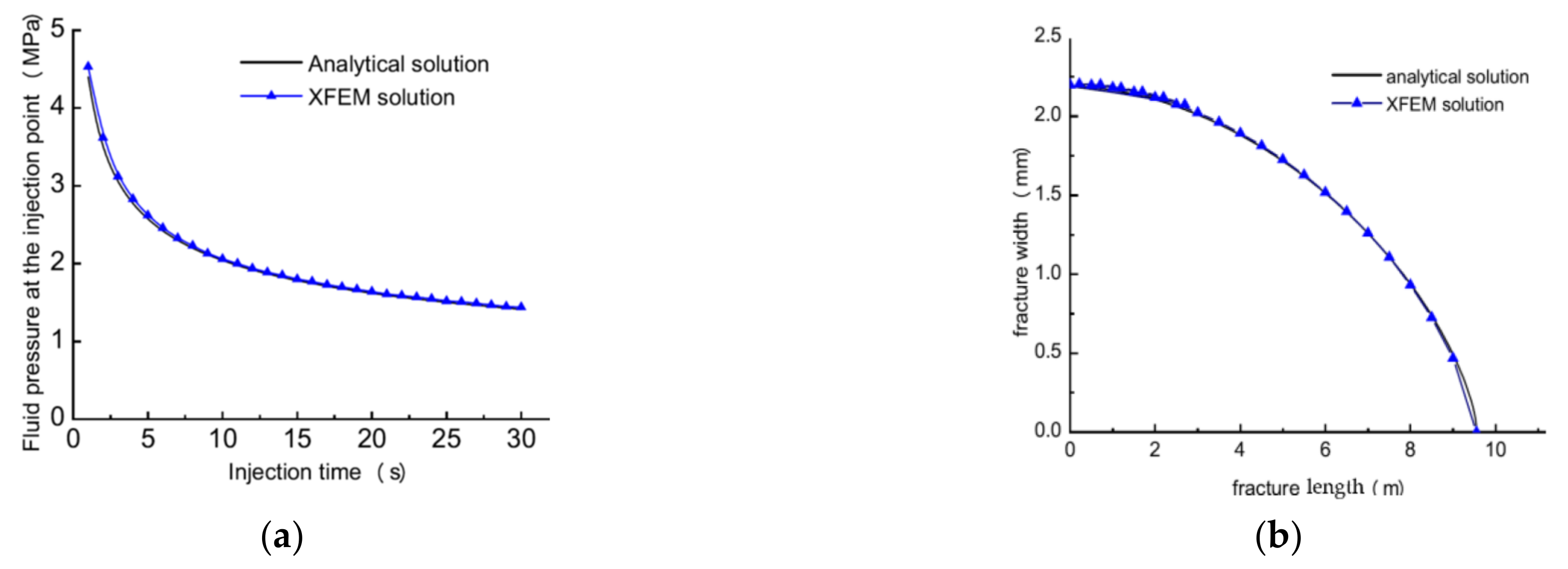
3.1. Model Verification

To verify the reliability of the model, the XFEM-based numerical solution of HF propagation and the 2D analytical solution from the plane strain Kristianovic-Geertsma-de Klerk (KGD) fracture model [38] were compared. During HF propagation, the energy from fluid pressurization is used to split the rock and overcome the fluid friction loss within the fracture [39]. Thus, according to the material parameters, the HF propagation mechanism is divided into toughness-dominated or viscosity-dominated regimes, which are described with the dimensionless fracture toughness Km, proposed by Bunger et al. [40], and expressed as:
K m = 4 2 π 1 / 2 K IC 1 v 2 E E 12 μ Q inj 1 v 2 1 / 4
HF propagation is toughness-dominated when Km > 4 and is viscosity-dominated when Km < 0.5.
In the XFEM model, a rectangular domain of 100 m by 180 m, is split into 3080 plane strain elements with pore pressure nodes (CPE4P), where the edge width is 180 m. The injection location is at the midpoint of the edge width. An original fracture is normal to the edge width, and an HF is initiated along the original fracture once the fluid is injected. To decrease the computing cost, the XFEM model was set to be symmetric about the edge width. The 1 mPa·s fracturing fluid was injected for 0.5 min at the rate of 0.06 m2/min. All the parameters of the XFEM model are given in Table 2. The dimensionless parameter Km in Equation (12) was 0.313, indicating HF propagation in the viscosity-dominated regime. The XFEM-based cohesive zone method (CZM) was applied in ABAQUS. The BK law is used to simulate the failure process in hydraulic fracturing [37]. The well-known Irwin formula was used to calculate the fracture energy according to the fracture toughness in Table 1 [41]. Figure 6 gives the numerical results of the fracture opening along with the HF and the injection pressure over the pumping time. The XFEM numerical results are consistent with the KGD analytical solution, indicating the reliability of the XFEM model.

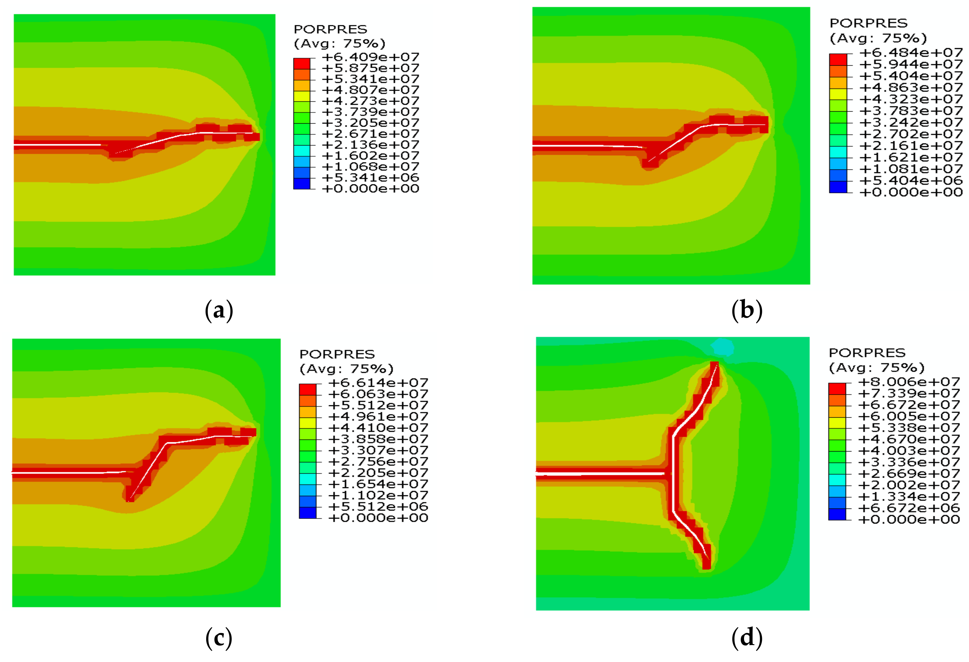
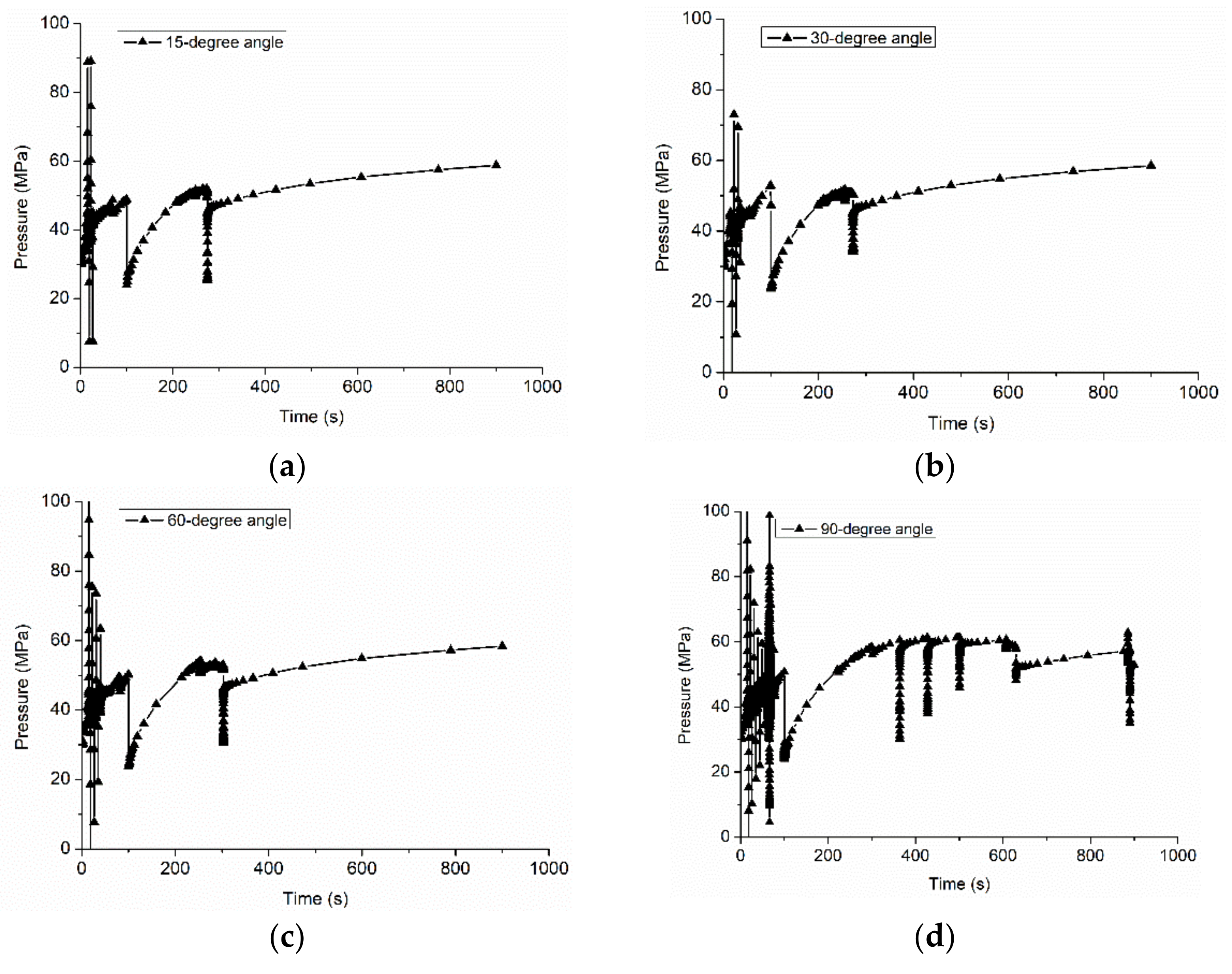
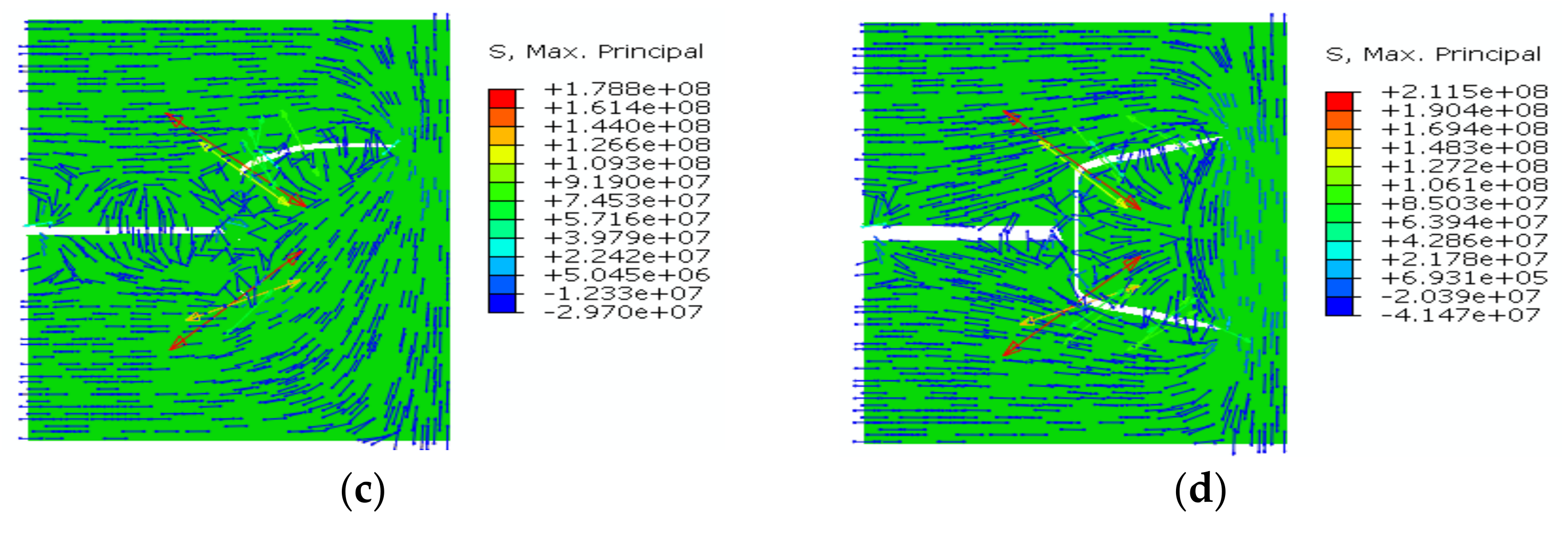
3.2. The Impact of Approaching Angle on Fracture Reorientation

The approaching angle is a key factor that affects HF propagation in naturally fractured formation [9]. It also affects HF re-initiation during refracturing in the naturally fractured reservoirs. The effects of approaching angles of 15°, 30°, 60°, and 90° on fracture reorientation were simulated, as shown in Figure 7, where PORPES is an abbreviation of the pore pressure. It was observed that the refracturing can be initiated from the tips of PFs and diverted into the direction of far-field stress. Moreover, an obvious pore pressure depletion zone occurred. The new fracture was only initiated from one tip of PFs at the approaching angle less than 90° and was initiated from both tips of PFs at the approaching angle of 90°. Thus, the new fracture can penetrate more reservoirs that are not stimulated in the first fracturing.
According to the σH direction at different approaching angles in Figure 8, stress reorientation occurred around HFs due to the poroelastic effect. With an approaching angle of 90°, the reversal stress zone appeared around the new fracture, and the local σH direction was consistent with the original direction of the far-field σh. When the fracture was diverted into the original far-field σH direction, the stress reorientation zone was not observed. The numerical results are consistent with the previous analysis of refracturing [19,20,42].
The injection pressure over the injection time at different approaching angles is shown in Figure 9. The first fracturing and refracturing steps lasted for 100 s and 900 s, respectively. It was observed that the injection pressure fluctuated more frequently as the approaching angle increased in the first fracturing step. In contrast, the injection pressure showed an upward trend but less fluctuation in the refracturing step. Moreover, the injection pressure in the refracturing was higher than that in the first fracturing, indicating that more energy is required to propagate the fracture to a new direction.

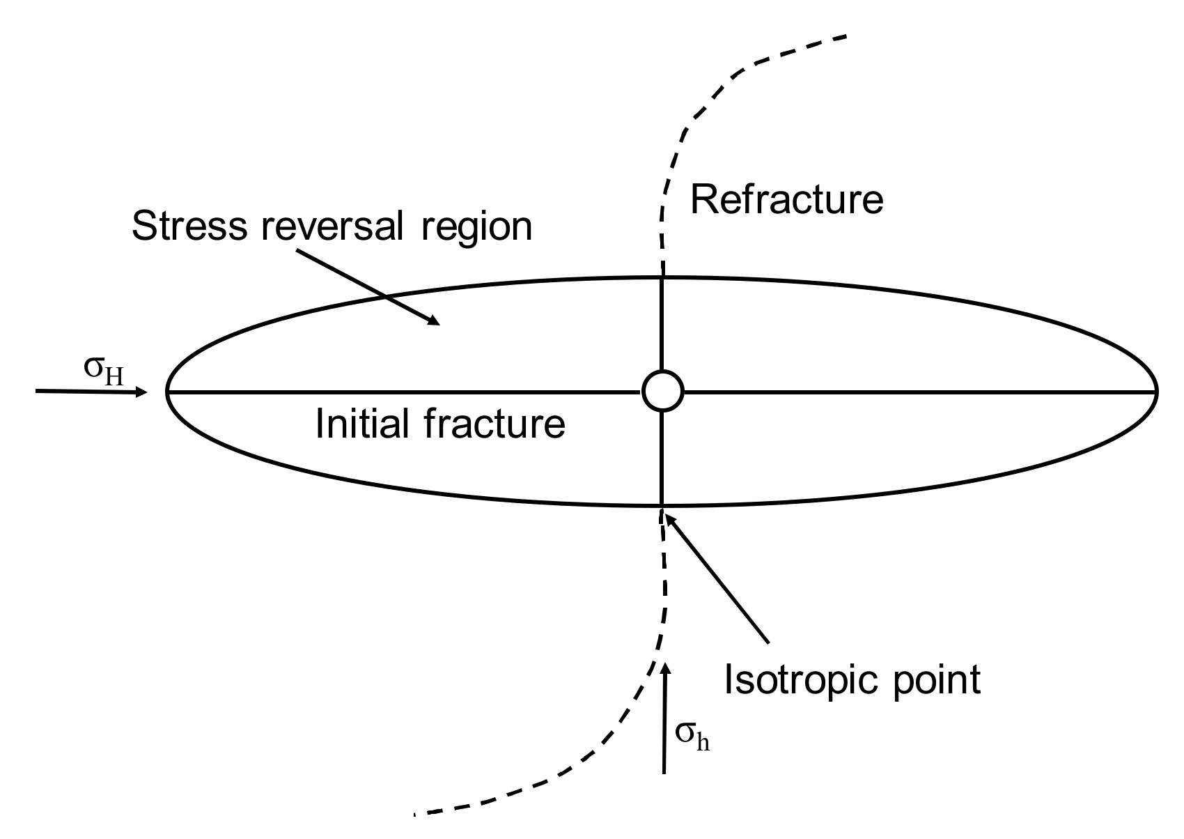
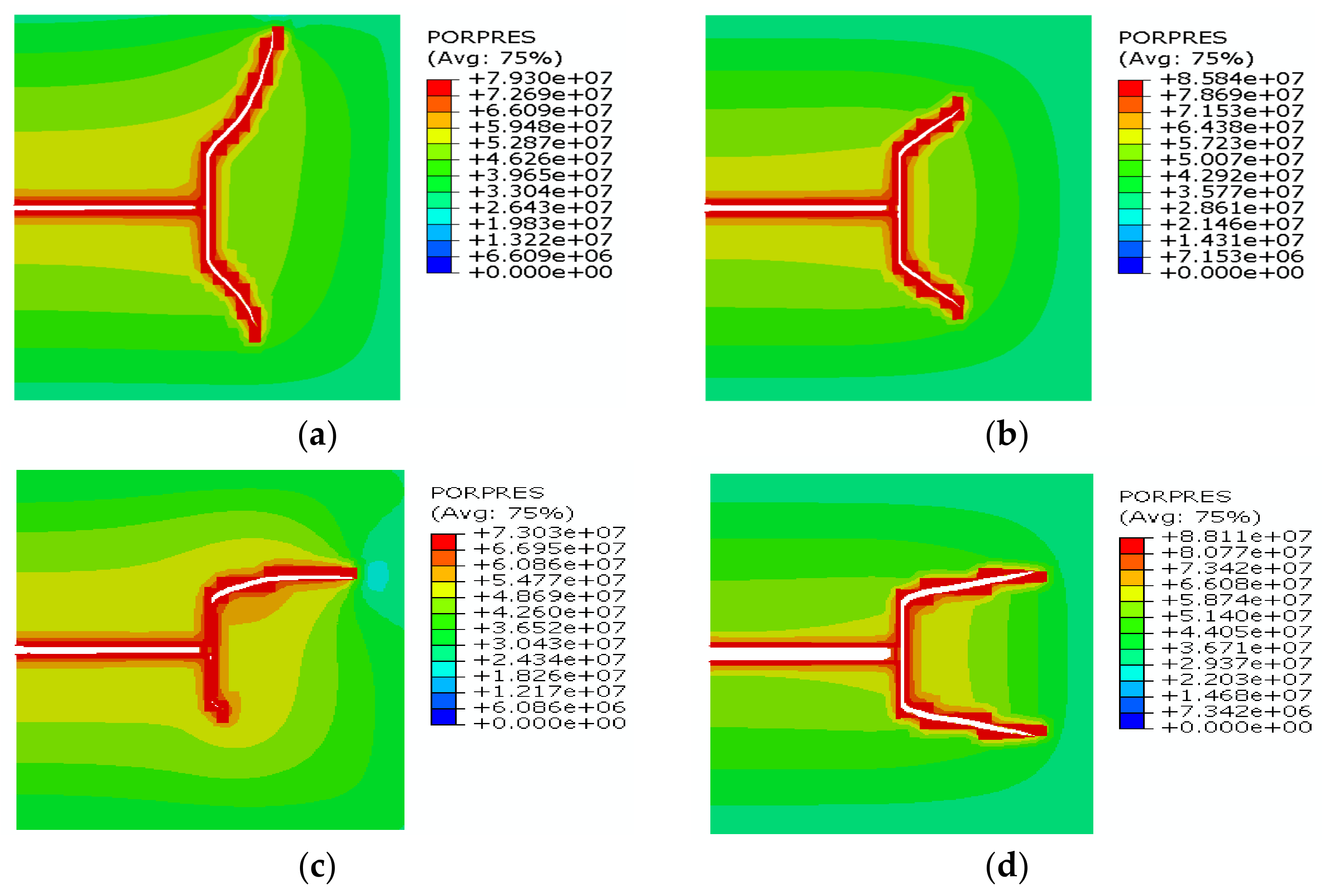
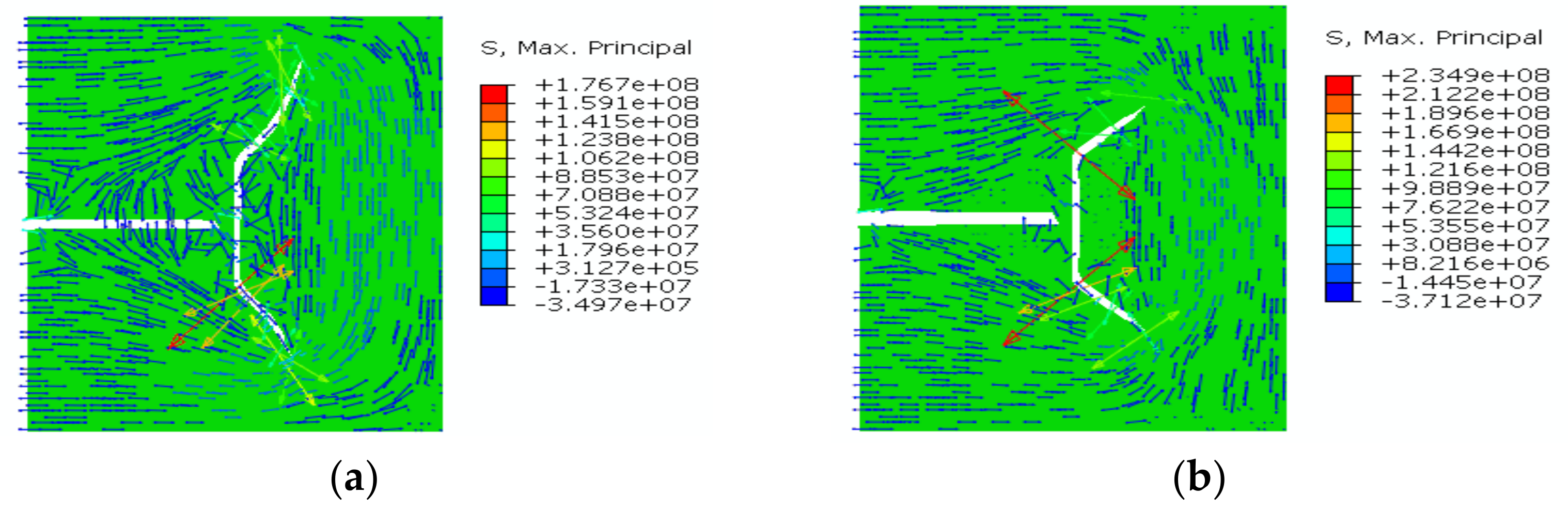
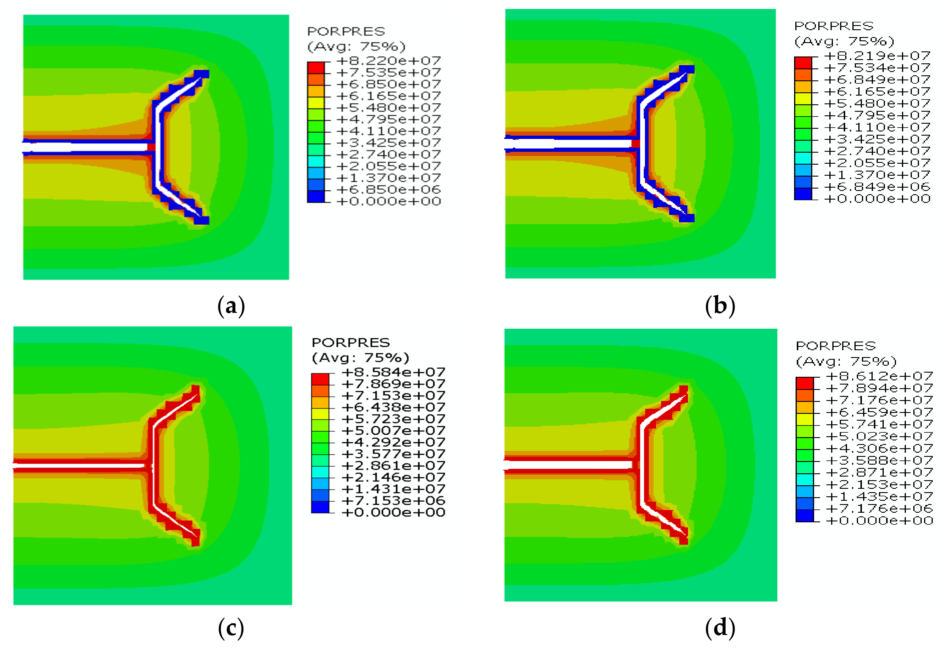
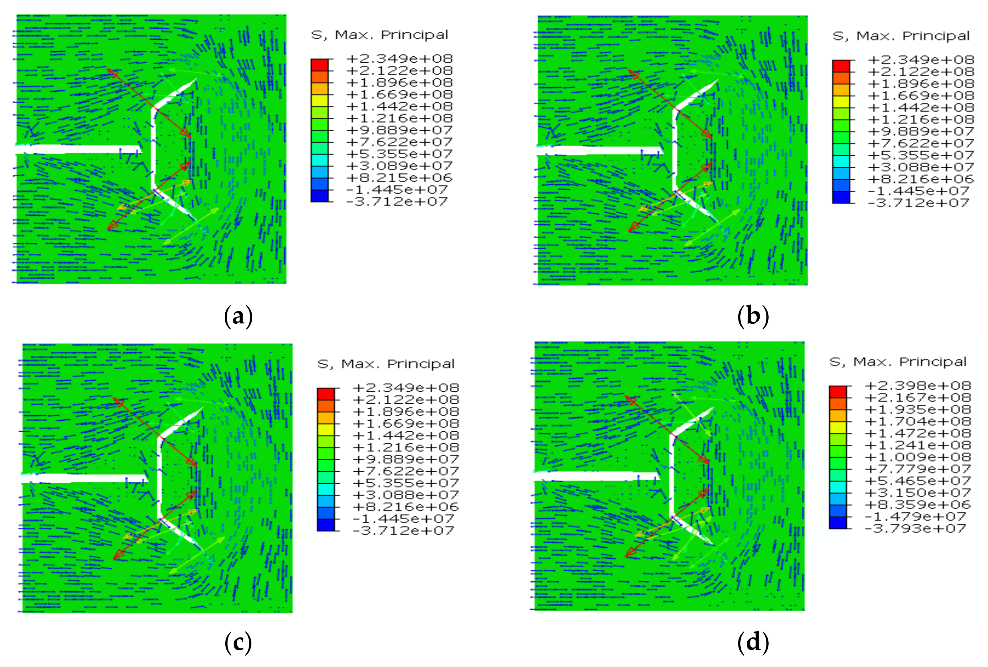
3.3. The Impact of Stress Difference on Fracture Reorientation

Stress anisotropy is also a key factor that affects HF propagation in naturally fractured formations. Thus, the impact of stress anisotropy on fracture reorientation during refracturing was simulated considering the stress differences of 0 MPa, 3 MPa, 6 MPa, and 9 MPa, as shown in Figure 10. It was observed that a fracture can be initiated from both tips of PFs and finally diverted into the far-field stress direction. This fracture diversion indicated that the fracture can be initiated from both new directions at different stress anisotropy at an approaching angle of 90°. Moreover, an obvious pore pressure depletion zone also occurred. The lower stress difference caused the stronger diversion capability of fracture. The numerical result indicated that the lower stress difference is beneficial for deeper penetration of the fracture to reservoirs.
According to the σH direction at various stress differences in Figure 11, stress reorientation occurred around HFs due to the poroelastic effect. With an approaching angle of 90 °, the reversal stress zone occurred around new fractures, and the local σH direction was consistent with the original far-field σh direction. The lower stress difference caused a relatively large stress reversal zone. The numerical results are consistent with the previous analysis of refracturing again [19,20,42].
The injection pressure over the injection time at different approaching angles is shown in Figure 12. The first fracturing and refracturing steps lasted for 100 s and 900 s, respectively. It was observed that the injection pressure fluctuated more frequently in the first fracturing step. In contrast, the injection pressure showed an upward trend but less fluctuation in the refracturing step. Moreover, the injection pressure in the refracturing step was higher than that in the first fracturing step, which indicated that more energy is required for fracture propagation to a new direction. The pressure drop in the refracturing step corresponded to new fracture initiation from both tips of PF.

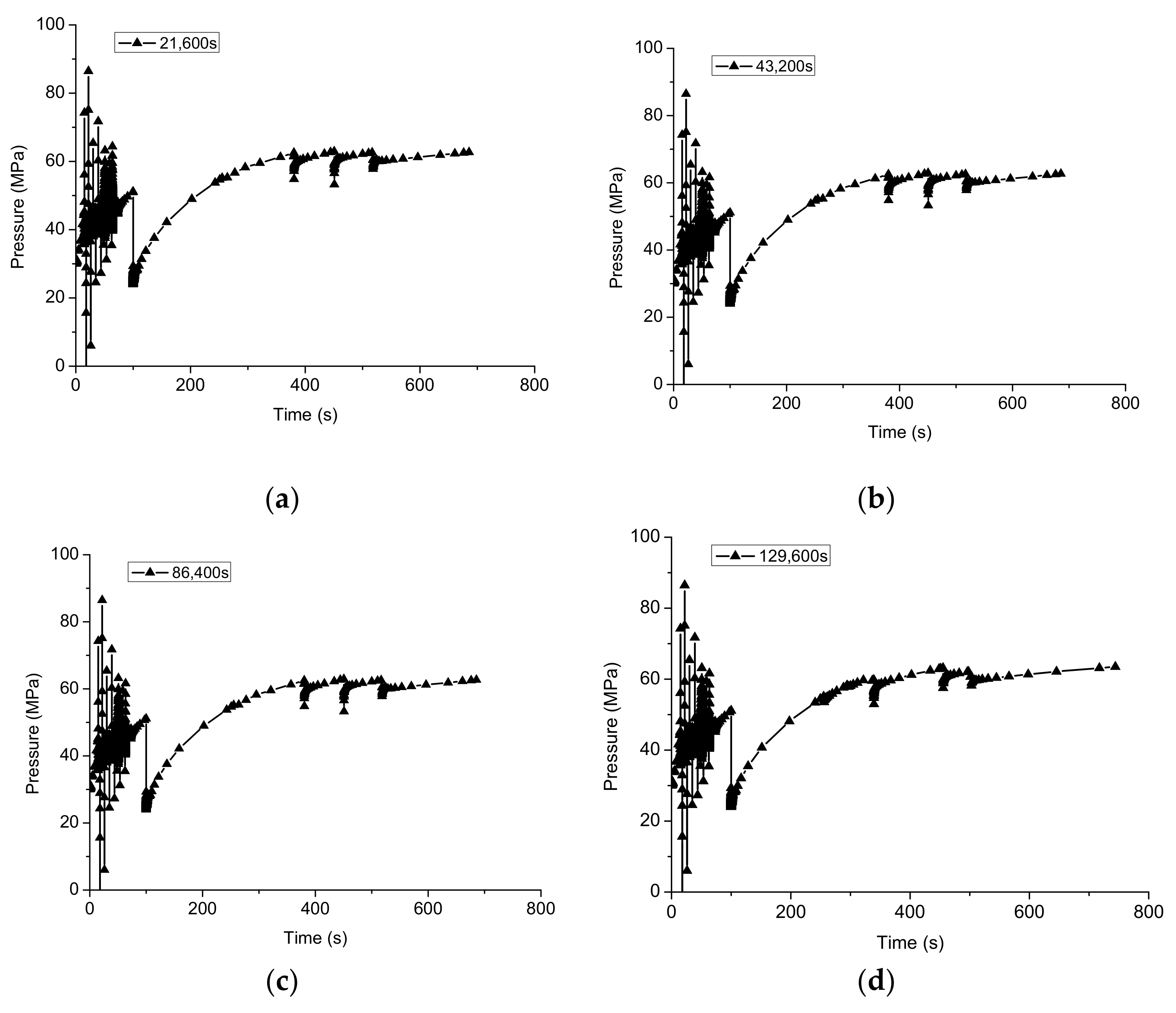
3.4. The Impact of Production Time on Fracture Reorientation

Here, the impact of production time on fracture reorientation during refracturing was simulated, considering the production time of 21,600 s, 43,200 s, 86,400 s, and 129,600 s, as shown in Figure 13. It was observed that new fracture can also be initiated from both tips of PFs and finally diverted into the far-field stress direction. The fracture diversion indicated that the new fracture can be initiated from both new directions at different production time at an approaching angle of 90°. Moreover, an obvious pore pressure depletion zone occurred. Nevertheless, the production time had no significant effect on new fracture propagation in these cases. The result was possibly due to the value of reservoir parameters in this simulation, the interaction between new and old fractures, and the stress field state.
The σH direction at different production time is illustrated in Figure 14. We observed that stress reorientation occurred around HFs due to the poroelastic effect, similar to the results illustrated above. This stress reversal zone was beneficial for the penetration of the fracture into unstimulated reservoirs.
The injection pressure over the injection time after different production times is illustrated in Figure 15. Similar to the results illustrated above, it was observed that the injection pressure fluctuated more frequently in the first fracturing step. In contrast, the injection pressure showed an upward trend but less fluctuation in the fracturing step. Moreover, the injection pressure in the fracturing step was higher than that in the first fracturing step, which indicates that more energy is required for new fracture propagation to a new direction. There was no distinct difference in injection pressure history, which led to the similar fracture propagation paths in Figure 13.

4. Conclusions

In this study, for the first time, numerical simulation was carried out using the XFEM-based CZM technique to illustrate how production-driven stress reorientation improves fracture complexity during refracturing. The junction enrichment function that reflects the mechanical interaction between HF and pre-existing fractures (PFs) was integrated into the XFEM-based refracturing model. The reliability of the XFEM refracturing model was verified by comparing the numerical results with the KGD analytical solution. The impact of approaching angle, stress difference, and production time on a new fracture initiation and propagation were discussed. The main conclusions are as follows:
The numeric simulation showed that both approaching angle and stress difference have more significant effects on refracture initiation and propagation than the production time. The impact of production time on stress reorientation was possibly due to the reservoir parameters, the interaction between HF and PF, and the stress state.
The stress reorientation was observed around refractures due to the poroelastic effect, which coincided with the previous analysis of refracturing. In particular, when the approaching angle was close to 90°, the stress reversal zone occurred, and the fracture complexity was improved because refractures could be initiated and diverted along with both tips of PFs. This fracture diversion was beneficial for contacting more reservoirs during refracturing.
The injection pressure fluctuated more frequently in the first fracturing step than in the refracturing step. Moreover, the injection pressure in the refracturing step showed an upward trend and it was higher than that in the first fracturing step, which indicated that more energy is required for refracture propagation to a new direction. The injection pressure drop in the refracturing step corresponded to the new fracture initiation from both tips of PFs. Our numerical simulation results give new insights into the mechanism of fracture complexity during refracturing.
The refracturing model simulated the production-induced stress orientation with XFEM. Nevertheless, the mechanical effect induced by proppant within the original hydraulic fractures was not considered in this paper, and it is our future work.

Author Contributions

Conceptualization, methodology, and supervision, A.D.T.; methodology, software, and writing—original draft preparation, D.W.; validation, M.W. and C.H.; writing—review and editing, B.Y. All authors have read and agreed to the published version of the manuscript.

Funding

Authors (except the second author) were supported financially by the Beijing Natural Science Foundation Project (3222030), the National Natural Science Foundation of China (51936001), and the PetroChina Science and Technology Innovation Foundation Project (2021DQ02-0201).

Institutional Review Board Statement

Not applicable.

Informed Consent Statement

Not applicable.

Data Availability Statement

Datasets related to this article can be found by connecting the corresponding author.

Conflicts of Interest

The authors declare no conflict of interest.

References

  1. Palmer, I.D. Induced Stresses Due to Propped Hydraulic Fracture in Coalbed Methane Wells. In Proceedings of the Society of Petroleum Engineers, Oklahoma City, OK, USA, 1 January 1993. [Google Scholar]
  2. Too, J.L.; Cheng, A.; Linga, P. Fracturing Methane Hydrate in Sand: A Review of the Current Status. In Proceedings of the Offshore Technology Conference, Houston, TX, USA, 20 March 2018. [Google Scholar]
  3. Gale, J.F.W.; Laubach, S.E.; Olson, J.E.; Eichhubl, P.; Fall, A. Natural Fractures in Shale: A Review and New Observations. AAPG Bull. 2014, 98, 2165–2216. [Google Scholar] [CrossRef]
  4. Economides, M.J.; Nolte, K.G. (Eds.) Reservoir Stimulation, 3rd ed.; Wiley: Chichester, UK; New York, NY, USA, 2000; ISBN 978-0-471-49192-7. [Google Scholar]
  5. Zhang, Q.; Hou, B.; Lin, B.; Liu, X.; Gao, Y. Integration of Discrete Fracture Reconstruction and Dual Porosity/Dual Permeability Models for Gas Production Analysis in a Deformable Fractured Shale Reservoir. J. Nat. Gas Sci. Eng. 2021, 93, 104028. [Google Scholar] [CrossRef]
  6. Hou, B.; Chang, Z.; Fu, W.; Muhadasi, Y.; Chen, M. Fracture Initiation and Propagation in a Deep Shale Gas Reservoir Subject to an Alternating-Fluid-Injection Hydraulic-Fracturing Treatment. SPE J. 2019, 24, 1839–1855. [Google Scholar] [CrossRef]
  7. Dahi-Taleghani, A. Fracture Re-Initiation As a Possible Branching Mechanism during Hydraulic Fracturing. In Proceedings of the American Rock Mechanics Association, Salt Lake City, UT, USA, 1 January 2010. [Google Scholar]
  8. Dahi-Taleghani, A.; Olson, J.E. How Natural Fractures Could Affect Hydraulic-Fracture Geometry. SPE J. 2014, 19, 161–171. [Google Scholar] [CrossRef]
  9. Dahi-Taleghani, A.; Olson, J.E. Numerical Modeling of Multistranded-Hydraulic-Fracture Propagation: Accounting for the Interaction between Induced and Natural Fractures. SPE J. 2011, 16, 575–581. [Google Scholar] [CrossRef]
  10. Maxwell, S.C.; Urbancic, T.I.; Steinsberger, N.; Zinno, R. Microseismic Imaging of Hydraulic Fracture Complexity in the Barnett Shale. In Proceedings of the Society of Petroleum Engineers, San Antonio, TX, USA, 1 January 2002. [Google Scholar]
  11. Yu, H.; Taleghani, A.D.; Lian, Z. On How Pumping Hesitations May Improve Complexity of Hydraulic Fractures, a Simulation Study. Fuel 2019, 249, 294–308. [Google Scholar] [CrossRef]
  12. Yu, H.; Dahi Taleghani, A.; Lian, Z.; Lin, T. On How Asymmetric Stimulated Rock Volume in Shales May Impact Casing Integrity. Energy Sci. Eng. 2020, 8, 1524–1540. [Google Scholar] [CrossRef]
  13. Zhou, F.; Liu, Y.; Yang, X.; Zhang, F.; Xiong, C.; Liu, X. Case Study: YM204 Obtained High Petroleum Production by Acid Fracture Treatment Combining Fluid Diversion and Fracture Reorientation. In Proceedings of the Society of Petroleum Engineers, Scheveningen, The Netherlands, 1 January 2009. [Google Scholar]
  14. Palisch, T.T.; Vincent, M.C.; Handren, P.J. Slickwater Fracturing: Food for Thought. In Proceedings of the Society of Petroleum Engineers, Alexandria, VA, USA, 1 January 2008. [Google Scholar]
  15. Warpinski, N.R.; Branagan, P.T. Altered-Stress Fracturing. J. Pet. Technol. 1989, 41, 990–997. [Google Scholar] [CrossRef]
  16. Siebrits, E.; Elbel, J.L.; Detournay, E.; Detournay-Piette, C.; Christianson, M.; Robinson, B.M.; Diyashev, I.R. Parameters Affecting Azimuth and Length of a Secondary Fracture During a Refracture Treatment. In Proceedings of the Society of Petroleum Engineers, New Orleans, LA, USA, 1 January 1998. [Google Scholar]
  17. Roussel, N.P.; Sharma, M.M. Quantifying Transient Effects in Altered-Stress Refracturing of Vertical Wells. SPE J. 2010, 15, 770–782. [Google Scholar] [CrossRef]
  18. Sneddon, I.N.; Elliot, H.A. The Opening of a Griffith Crack under Internal Pressure. Q. Appl. Math. 1946, 4, 262–267. [Google Scholar] [CrossRef] [Green Version]
  19. Elbel, J.L.; Mack, M.G. Refracturing: Observations and Theories. In Proceedings of the Society of Petroleum Engineers, Oklahoma City, OK, USA, 1 January 1993. [Google Scholar]
  20. Li, X.; Wang, J.; Elsworth, D. Stress Redistribution and Fracture Propagation during Restimulation of Gas Shale Reservoirs. J. Pet. Sci. Eng. 2017, 154, 150–160. [Google Scholar] [CrossRef]
  21. Bruno, M.S.; Nakagawa, F.M. Pore Pressure Influence on Tensile Fracture Propagation in Sedimentary Rock. Int. J. Rock Mech. Min. Sci. Geomech. Abstr. 1991, 28, 261–273. [Google Scholar] [CrossRef]
  22. Berchenko, I.; Detournay, E. Deviation of Hydraulic Fractures through Poroelastic Stress Changes Induced by Fluid Injection and Pumping. Int. J. Rock Mech. Min. Sci. 1997, 34, 1009–1019. [Google Scholar] [CrossRef]
  23. Boone, T.J.; Wawrzynek, P.A. Exploiting Poroelastic Effects and Permeability Contrasts to Control Fracture Orientation. In Proceedings of the Society of Petroleum Engineers, Delft, The Netherlands, 1 January 1994. [Google Scholar]
  24. Dalkhaa, C.; Azzolina, N.A.; Chakhmakhchev, A.; Kurz, B.A.; Sorensen, J.A.; Gorecki, C.D.; Harju, J.A. Refracturing in the Bakken—An Analysis of Data from Across North Dakota. In Proceedings of the OnePetro, Houston, TX, USA, 20 June 2022. [Google Scholar]
  25. Wright, C.A.; Conant, R.A. Hydraulic Fracture Reorientation in Primary and Secondary Recovery from Low-Permeability Reservoirs. In Proceedings of the Society of Petroleum Engineers, Dallas, TX, USA, 1 January 1995. [Google Scholar]
  26. Wang, Y.; Yao, Y.; Wang, L.; Hu, Y.; Wu, H.; Wang, H. Case Study: Analysis of Refracturing Crack Orientation-Angle and Extension-Length in Tight Gas Reservoir, Sulige Gasfield of China. In Proceedings of the OnePetro, Madrid, Spain, 6 June 2022. [Google Scholar]
  27. Wang, D.-B.; Zhou, F.-J.; Li, Y.-P.; Yu, B.; Martyushev, D.; Liu, X.-F.; Wang, M.; He, C.-M.; Han, D.-X.; Sun, D.-L. Numerical Simulation of Fracture Propagation in Russia Carbonate Reservoirs during Refracturing. Pet. Sci. 2022, in press. [Google Scholar] [CrossRef]
  28. Chen, J.; Zhang, Q.; Zhang, J. Numerical Simulations of Temporary Plugging-Refracturing Processes in a Conglomerate Reservoir Under Various In-Situ Stress Difference Conditions. Front. Phys. 2022, 9, 825. [Google Scholar] [CrossRef]
  29. Melenk, J.M.; Babuška, I. The Partition of Unity Finite Element Method: Basic Theory and Applications. Comput. Methods Appl. Mech. Eng. 1996, 139, 289–314. [Google Scholar] [CrossRef] [Green Version]
  30. Belytschko, T.; Black, T. Elastic Crack Growth in Finite Elements with Minimal Remeshing. Int. J. Numer. Methods Eng. 1999, 45, 601–620. [Google Scholar] [CrossRef]
  31. Abaqus 6.14-1 Documentation; Dassault Systemes Simulia Corporation: Providence, RI, USA, 2014.
  32. Song, J.; Areias, P.M.A.; Belytschko, T. A Method for Dynamic Crack and Shear Band Propagation with Phantom Nodes. Int. J. Numer. Methods Eng. 2006, 67, 868–893. [Google Scholar] [CrossRef]
  33. Ma, T.; Zhang, K.; Shen, W.; Guo, C.; Xu, H. Discontinuous and Continuous Galerkin Methods for Compressible Single-Phase and Two-Phase Flow in Fractured Porous Media. Adv. Water Resour. 2021, 156, 104039. [Google Scholar] [CrossRef]
  34. Xu, Y.; Sheng, G.; Zhao, H.; Hui, Y.; Zhou, Y.; Ma, J.; Rao, X.; Zhong, X.; Gong, J. A New Approach for Gas-Water Flow Simulation in Multi-Fractured Horizontal Wells of Shale Gas Reservoirs. J. Pet. Sci. Eng. 2021, 199, 108292. [Google Scholar] [CrossRef]
  35. Rice, J.R.; Cleary, M.P. Some Basic Stress Diffusion Solutions for Fluid—Saturated Elastic Porous Media with Compressible Constituents. Rev. Geophys. 1976, 14, 227–241. [Google Scholar] [CrossRef]
  36. Barenblatt, G.I. The Mathematical Theory of Equilibrium Cracks in Brittle Fracture. In Advances in Applied Mechanics; Dryden, H.L., von Kármán, T., Kuerti, G., van den Dungen, F.H., Howarth, L., Eds.; Elsevier: Amsterdam, The Netherlands, 1962; Volume 7, pp. 55–129. [Google Scholar]
  37. Benzeggagh, M.L.; Kenane, M. Measurement of Mixed-Mode Delamination Fracture Toughness of Unidirectional Glass/Epoxy Composites with Mixed-Mode Bending Apparatus. Compos. Sci. Technol. 1996, 56, 439–449. [Google Scholar] [CrossRef]
  38. Geertsma, J.; De Klerk, F. A Rapid Method of Predicting Width and Extent of Hydraulically Induced Fractures. J. Pet. Technol. 1969, 21, 1571–1581. [Google Scholar] [CrossRef]
  39. Detournay, E. Propagation Regimes of Fluid-Driven Fractures in Impermeable Rocks. Int. J. Geomech. 2004, 4, 35–45. [Google Scholar] [CrossRef]
  40. Bunger, A.P.; Detournay, E.; Garagash, D.I. Toughness-Dominated Hydraulic Fracture with Leak-Off. Int. J. Fract. 2005, 134, 175–190. [Google Scholar] [CrossRef]
  41. Irwin, G. Fracture Strength Relative to Onset and Arrest of Crack Propagation. In Proceedings of the Proc ASTM, Philadelphia, PA, USA, 1 January 1958; Volume 58, pp. 640–657. [Google Scholar]
  42. Roussel, N.P.; Sharma, M.M. Role of Stress Reorientation in the Success of Refracture Treatments in Tight Gas Sands. SPE Prod. Oper. 2012, 27, 346–355. [Google Scholar] [CrossRef]
Figure 1. Schematic of fracture reorientation during refracturing.
Sustainability 14 09422 g001
Figure 2. Principle of the phantom nodes’ method.
Sustainability 14 09422 g002
Figure 3. Fluid flow within a fractured element.
Sustainability 14 09422 g003
Figure 4. Typical linear traction–separation constitutive behavior.
Sustainability 14 09422 g004
Figure 5. Physical model of refracturing.
Sustainability 14 09422 g005
Figure 6. Numerical results of the analytical solution and the XFEM model: (a) injection pressure at the fracture mouth; (b) fracture opening.
Sustainability 14 09422 g006
Figure 7. The impact of approaching angle on fracture reorientation: (a) 15°; (b) 30°; (c) 60°; and (d) 90°. Deformation factor = 20.
Sustainability 14 09422 g007
Figure 8. Direction of σH at different approaching angles: (a) 15°; (b) 30°; (c) 60°; and (d) 90°. Deformation factor = 20.
Sustainability 14 09422 g008
Figure 9. Injection pressure at different approaching angles: (a) 15°; (b) 30°; (c) 60°; and (d) 90°.
Sustainability 14 09422 g009
Figure 10. The impact of stress difference on fracture reorientation: (a) 0 MPa; (b) 3 MPa; (c) 6 MPa; (d) 9 MPa. Deformation factor = 20.
Sustainability 14 09422 g010
Figure 11. Direction of σH at different stress differences: (a) 0 MPa; (b) 3 MPa; (c) 6 MPa; (d) 9 MPa. Deformation factor = 20.
Sustainability 14 09422 g011aSustainability 14 09422 g011b
Figure 12. Injection pressure over the injection time at different stress differences: (a) 0 MPa; (b) 3 MPa; (c) 6 MPa; (d) 9 MPa.
Sustainability 14 09422 g012
Figure 13. The impact of production time on fracture reorientation: (a) 21,600 s; (b) 43,200 s; (c) 86,400 s; (d) 129,600 s. Deformation factor = 20.
Sustainability 14 09422 g013
Figure 14. Direction of σH at different production time: (a) 21,600 s; (b) 43,200 s; (c) 86,400 s; (d) 129,600 s. Deformation factor = 20.
Sustainability 14 09422 g014
Figure 15. Injection pressure over injection time at different production time: (a) 21,600 s; (b) 43,200 s; (c) 86,400 s; (d) 129,600 s.
Sustainability 14 09422 g015
Table 1. Parameters of the refracturing simulation model.
ParametersValues
Elastic modulus, E15,000 MPa
Poisson’s ratio, ν0.25
Critical fracture energy, GC250 Pa·m
Injection rate, Qinj0.001 m2/s
Fluid viscosity, μ1 mPa·s
Tensile strength, Tmax3 MPa
Filtration coefficient, cL5.879 × 10−13 Pa/(m·s)
Rock porosity, ϕ 0.1
Rock permeability, k0.01 mD
Original pore pressure, pp30 MPa
Far-field stress, σH/σh/σv15/12/18 MPa
Injection rate, Qinj2 × 10−3 m2/s
Injection time, tinj100 s
Production rate, Qprod2 × 10−4 m2/s
Production time, tprod86,400 s
Table 2. Parameters of 2D hydraulic fracturing simulation.
ParametersValues
Elastic modulus, E20,000 MPa
Poisson’s ratio, ν0.22
Fracture toughness, KIC100 kPa·m1/2
Flow rate, Qinj0.06 m2/min
Fluid viscosity, μ100 mPa·s
Dimensionless parameter, Km0.313
Time, t0.5 min
Publisher’s Note: MDPI stays neutral with regard to jurisdictional claims in published maps and institutional affiliations.

