Article

Comparative Study on the Isothermal Reduction Kinetics of Iron Oxide Pellet Fines with Carbon-Bearing Materials

1
State Key Laboratory of Advanced Special Steel, Shanghai Key Laboratory of Advanced Ferrometallurgy, School of Materials Science and Engineering, Shanghai University, Shanghai 200444, China
2
Central Metallurgical Research and Development Institute (CMRDI), P.O. Box 87, Helwan 11722, Egypt
3
Process Metallurgy Research Group, Faculty of Technology, University of Oulu, 90100 Oulu, Finland
*
Authors to whom correspondence should be addressed.
Sustainability 2022, 14(14), 8647; https://doi.org/10.3390/su14148647
Submission received: 3 June 2022 / Revised: 4 July 2022 / Accepted: 12 July 2022 / Published: 14 July 2022

Abstract

:
The isothermal reduction of iron oxide pellet fines–carbon composites was investigated at temperatures of 900–1100 °C. The reduction reactions were monitored using the thermogravimetric (TG) technique. Alternatively, a Quadruple Mass Spectrometer (QMS) analyzed the CO and CO2 gases evolved from the reduction reactions. The effect of temperature, carbon source, and reaction time on the rate of reduction was extensively studied. The phase composition and the morphological structure of the reduced composites were identified by X-ray diffraction (XRD) and a scanning electron microscope (SEM). The results showed that the reduction rate was affected by the temperature and source of carbon. For all composite compacts, the reduction rate, as well as the conversion degree (α) increased with increasing temperature. Under the same temperature, the conversion degree and the reduction rate of composites were greater according to using the following carbon sources order: Activated charcoal > charcoal > coal. The reduction of the different composites was shown to occur stepwise from hematite to metallic iron. The reduction, either by activated charcoal or charcoal, is characterized by two behaviors. During the initial stage, the chemical reaction model (1 − α)−2 controls the reduction process whereas the final stage is controlled by gas diffusion [1 − (1 − α)1/2]2. In the case of reduction with coal, the reduction mechanism is regulated by the Avrami–Erofeev model [−ln (1−α)2] at the initial stage. The rate-controlling mechanism is the 3-D diffusion model (Z-L-T), namely [(1−α)−1/3−1]2 at the latter stage. The results indicated that using biomass carbon sources is favorable to replace fossil-origin carbon-bearing materials for the reduction of iron oxide pellet fines.

1. Introduction

Iron and steel-making are one of the most energy- and carbon-intensive, polluting, and greenhouse-gas-emitting sectors, accounting for 5–7 percent of the worldwide CO2 emissions [1]. The amount of CO2 released by steel-making plants is expected to rise to approximately 3.0 billion tonnes by 2050 [2]. Coke and other fossil fuels account for over 70% of crude steel production [3]. In the search for strategies to decrease the amount of emitted CO2, biomass is considered an important promising option. In the iron and steel industry, biomass has been recognized as one alternative raw resource for replacing part of fossil fuels [4]. Nowadays, the greatest issues facing steel-making are environmental pollution and CO2 emissions. As a result, the expansion of the steel sector needs the development of new techniques that are both commercially and environmentally viable [5]. In recent years, global population growth has necessitated increased industrial production and, as a result, rising energy demand. In this view, using renewable energy sources (such as biomass) as an alternative to fossil fuels appears to be a vital option for lowering greenhouse gas emissions [6,7]. According to Safarian et al. [8], biomass accounts for only 9.7 percent of primary energy, whereas fossil fuels account for 81.4 percent.
Biomass is a carbon-neutral and renewable energy source. The utilization of biomass for energy in the industry has the potential to minimize CO2 emissions and fossil fuel consumption. Coke and coal can be substituted in the ironmaking process due to the abundance of biomass sources. It has been stated that biomass has been used in iron ore sintering, blast furnaces, and some innovative iron-making processes [9,10,11,12]. Biomass can reduce coke breeze and SO2 emissions during sintering without affecting the sinter quality [9,10]. Biomass can also help to minimize the amount of coke used in a blast furnace [11]. Charcoal can substitute coke directly inside the blast furnace. An iron ore composite with biomass char can reduce coke indirectly in the furnace [12]. Biomass is employed in some novel technologies, such as two-step direct reduction ironmaking technology, in addition to applications in the traditional ironmaking process. Iron ore and biomass pellets are utilized as raw materials in this process, which results in sponge iron [13,14].
In addition to the energy issue, one of the major issues facing worldwide steel production is the handling of wastes such as slags, dust, mill scales, sludges, and fines generated at different stages of the iron and steel manufacturing process. The utilization of these wastes is a critical strategy for conserving resources and reducing pollution [15,16]. Moreover, replacing by-products with natural resources in manufacturing processes can save energy and enhance efficiency. This includes decreasing the exploitation of natural resources and pollution, as well as the utilization of environmentally friendly substitute raw materials [15,16,17,18].
Composites containing iron oxide as well as carbon sources have recently received a great deal of attention in the iron-making process [19,20]. The utilization of composite in the blast furnace (BF) was observed not only to decrease the use of coke but also to improve the performance, consequently increasing productivity [3]. The effect of carbon content on the reduction rate was previously investigated by different researchers [3,12,21,22,23,24,25,26,27]. Many researchers [28,29,30,31] reported that as the amount of carbon in the composite increased, the reduction rate increased monotonically at 1000 °C. Whereas others [24,31,32] have shown that raising the amount of carbon over the stoichiometric value has little impact on the reduction degree at temperatures over 1200 °C. Yang et al. [33] studied the effect of several variables on the reduction behavior of composites such as a temperature range of 1100–1400 °C, the gas flow rate, and the graphite particle size. It was found that direct reduction controlled the reduction reaction in the early stages of the reaction, while the reduction process was controlled by indirect reduction mixed with a carbon solution as the partial pressure of CO increased with temperature. Liu et al. [34] investigated the reduction of an iron ore–coal mixture. They concluded that the reduction of magnetite to wustite occurred between 740 and 870 °C. Wustite is reduced to metallic iron at approximately 870–1200 °C and the reduction rate is slower at 740–800 °C than at 800–870 °C. Sun et al. [35] studied the reduction kinetics of oolitic iron ore-coal at 1423–1573 K. They concluded that the C/O molar ratio and the temperature have a considerable impact on the reduction rate and reduction degree. The reduction reaction was divided into three steps, each with an apparent activation energy of 48.26, 69.80, and 127.58 kJ/mol, respectively. The reduction reaction during the first stages is regulated by the combined effect of the chemical reaction and gas diffusion. During the second step, the reduction process is dominated by the chemical reaction, whereas the coupled solid-state diffusion and boundary reaction control the final stage. The reduction of iron ore fines with different carbon sources was investigated non-isothermally using different heating rates by Hammam et al. [36]. It was concluded that the heating rates have a significant influence on the conversion degree and the rate of reduction. At the same heating rate, the reduction extent and rate of reduction were both greater when charcoal was used instead of coal. When utilizing coal, the reduction behavior progressed from Fe2O3 to Fe3O4, then from Fe3O4 to FeO, and ultimately from FeO to Fe. When using charcoal, the reduction reaction progressed from Fe2O3 to FeO, then from FeO to Fe. The reduction mechanism is dominated by gas diffusion at the earliest stages, while the later stages are controlled by the nucleation reaction.
Currently, researchers all over the world are interested in researching and finding future raw materials for the iron-making industry. Understanding the reaction kinetics of such materials, as well as their impact on process parameters and performance, has prompted scientists to continue their research to obtain better insight into the reduction kinetics of these materials. The current study is planned to investigate the isothermal reduction kinetics of fines rejected from iron oxide pellets in direct reduction (DR) plants with different biomass materials such as activated charcoal and charcoal. Composite compacts were tested at different temperatures (900–1100 °C) in the presence of an argon (Ar) atmosphere. The reduction kinetics was investigated for activated charcoal and charcoal and then compared with those of coal.

2. Experimental

2.1. Raw Materials

2.1.1. Iron Oxide Pellet Fines

Iron oxide pellet fines utilized in this research were obtained from the transportation and handling of iron oxide pellets in the DR plant (Al-Ezz El-Dekheila steel Company, Alexandria, Egypt). The chemical composition, mean particle size, and main phases of iron oxide pellet fines are illustrated elsewhere [36].

2.1.2. Carbon-Bearing Materials

Activated charcoal, charcoal, and coal are the carbon-bearing materials that are used as reductants. Their proximate analysis is given in Table 1. The activated charcoal has higher fixed carbon and lower ash content than charcoal and coal. The three reductants have nearly the same mean particle size of <100 μm. The surface area analyzer (Quantachrome, Nova 2000, Boynton Beach, FL, USA) was used to measure the specific surface area of the three reductants. The specific surface area of activated charcoal, charcoal, and coal are 817.3, 625.5, and 316.4 cm2/g, respectively.

Reactivity Behavior

The gasification behavior and the reactivity were assessed for the selected carbon-bearing materials in CO2 gas up to 1100 °C using a heating rate of 10 °C/min and holding time of 40 min as shown in Figure 1. It is clear that all of the carbon-bearing materials have exhibited three weight-loss steps (dehydration, de-volatilization, and gasification). The dehydration stage of the three types is nearly at the same temperature range up to 200 °C with mass loss values of 9, 4.5, and 4.5 wt.% for charcoal, activated charcoal, and coal, respectively. The de-volatilization stage indicates that the activated charcoal and charcoal have low volatiles with a mass loss of 12 wt.% and 14 wt.% at temperature ranges of approximately 200–700 °C and 200–780 °C, respectively, with small peaks in the DTG curve. Meanwhile, in the case of coal, the liberation of coal volatiles began at 200 and ended at approximately 800 °C with a mass loss of approximately 33 wt.% with a marked peak in the DTG curve. These volatiles cause the appearance of an intense peak of CO gas at the same temperature range. Finally, the gasification step (III) shows a difference in the starting temperature between the three types of carbon-bearing materials. The gasification temperature of activated charcoal starts at approximately 700 °C with a mass loss of 80 wt.% and a continuous marked stream of CO gas and stops after 20 min of holding at 1100 °C. Meanwhile, the gasification of charcoal starts at 780 °C with a mass loss of 73 wt.% and a detectable amount of CO gas and terminates after 10 min of holding time at 1100 °C. On the other hand, the gasification temperature of coal is shifted to a higher temperature at approximately 800 °C with the lowest mass loss of 57 wt.% and a low amount of CO gas. The results of the thermal analysis of the three carbon-bearing materials are consistently reliable with the proximate analysis, as shown in Table 1. It is worth mentioning that the difference in the gasification temperature of the carbon-bearing materials may be related to the variations in the specific surface area, active sites, porosity, as well as the amount of fixed carbon. Activated charcoal appears to be the most reactive carbon-bearing substance, followed by charcoal, and finally coal.

2.2. Compact Preparation

First, self-reducing mixtures were prepared by gentle but thorough blending of iron oxide pellet fines with activated charcoal, charcoal, or coal in an agate mortar and then in a ball mill for 1 h to ensure homogeneity. The quantity of carbon was computed and adjusted at a 3:1 molar ratio to guarantee that all reducible oxygen in the iron oxide pellet fines sample was eliminated. Compacts were formed by moistening the mixture with 6% distilled water, then compressing similar weights (1.5 g) in a cylindrical mold (d = 10 mm) at 20 kg/cm2 with a hydraulic press to achieve a uniform size and shape of compacts. The produced composite compacts were dried for 24 h at 110 °C before being kept in a desiccator for future testing. Three types of composite compacts, namely iron oxide pellet fines-activated charcoal, iron oxide pellet fines-charcoal, and iron oxide pellet fines-coal were produced and are hereinafter named composites I, II, and III, respectively.
The porosity of the different composites was measured by a mercury pore sizer (Micromeritics Pore Sizer 9320, Norcross, GA, USA). The relationship between the cumulative pore volumes and incremental volume against the pore diameter is shown in Figure 2. It can be seen that composite I and composite II give a wide range of pore sizes whereas composite III shows a relatively narrow range of pore sizes. The total porosity of composite I, composite II, and composite III is 39.63, 32.55, and 26.24%, respectively.
The reduction conversion (α) was determined by using the mass loss data in Equation (1)
α = W i     W t W i     W
where Wi is the initial weight of the sample, Wt is the actual weight of the sample at a particular time, and W∞ is the maximum theoretical weight loss.

2.3. Reduction System and Procedure

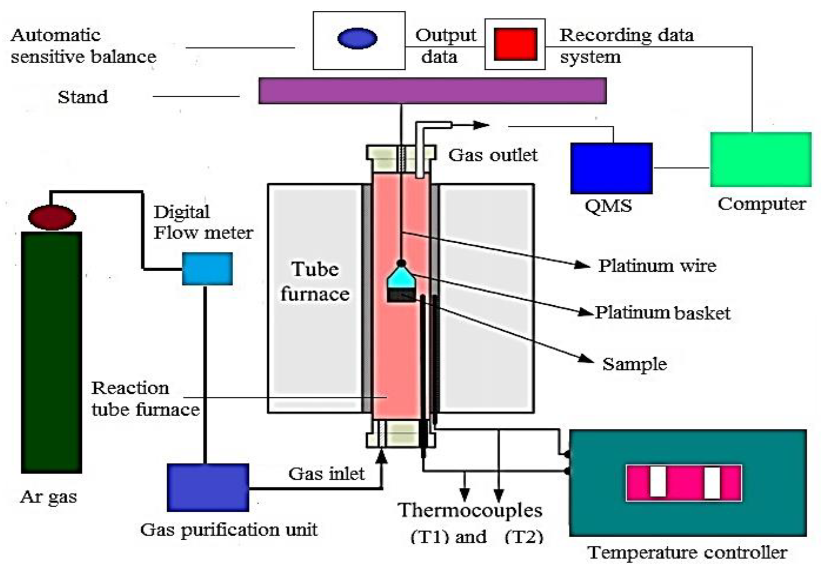
During the experiments, the total mass loss was continually recorded using the (TG) approach to follow the reduction reaction of composites. Furthermore, an advanced gas analyzer is employed to measure the amounts of carbon monoxide and carbon dioxide in the off-gases. The reduction apparatus is depicted schematically in Figure 3. The reduction system consists of a vertical tube furnace, equipped with an alumina reaction tube and an automated sensitive balance at the top. The output of the balance is coupled to the recording system for continual weight loss monitoring. The control parts consist of two different thermocouples (T1 and T2). Thermocouples T1 and T2 are used to measure the furnace and the sample temperatures, respectively.
Composites are isothermally reduced at 900–1100 °C in a purified argon atmosphere. The furnace is pre-heated to a specified temperature and kept there for approximately 5 min in each test. During the heating process of the furnace, argon gas is supplied at a flow rate of 500 mL/min and remained constant until the experiment is completed. The compact was then put in a platinum basket supported from the balance arm by platinum wire before being deposited in the hot zone of the furnace. During experiments, the weight loss was continually measured as a function of time until the sample weight remains constant. After the experiment was completed, the furnace was cooled down to ambient temperature and the reduced sample was quickly taken to avoid re-oxidation and stored in a desiccator for subsequent characterization.

3. Results and Discussion

3.1. Effect of Temperature on the Reduction of Composites

Figure 4a–c shows the variation in the calculated extents of reduction and the reaction time for composites I, II, and III at 900–1100 °C, respectively. It can be observed that the reduction rate was clearly affected by the temperature. For a given composite compact, the measured weight loss was more obvious at the initial stages of reduction up to specific extents based on the applied temperature. The high reduction rate was followed by a significant decrease at subsequent stages until the reduction reaction was completed, resulting in a plateau form at the last reduction stages. The reduction extent to which this plateau occurred increased with a rise in temperature. The reduction processes of hematite to magnetite and magnetite to wustite, as well as the gasification of carbon, are responsible for the high rate of reduction at the beginning and middle stages. In the last stages, the rate of reduction slows down due to the relatively slower reduction reaction of wustite to metallic iron, which is considered the rate-controlling step in the reduction process. The type of carbon-bearing material has a considerable impact on the reduction behavior at lower temperatures of 900 and 950 °C. At 1000 °C, the reduction rates of composites I and composite II are higher and close to each other, which is not the case with composite III where the reduction rate is relatively lower. As the temperature increased to 1100 °C, the difference between the rates of reduction for all composites was decreased and the reduction extents reached almost 100%. This indicated that the influence of temperature on the rate of reduction became more pronounced and the type of carbon source had a smaller effect at such high temperatures.

3.2. Kinetics Analysis

The rate of reduction reactions (r) can be described by the differential of the conversion degree (α) and time (t) as follows [37]:
r =   d α d t = k ( T ) f ( α )    
where k(T) represents the reaction rate constant depending on the applied temperature (T) and f(α) expresses the function of the mechanism that depicts the mechanism during the reduction reaction. There are numerous models tabulated elsewhere [37,38] for evaluating the most probable reduction mechanism and the kinetic parameters.
Vyazovkin et al. [39] proposed that the integral approach was the optimum method of analyzing the data resulting in thermal analysis (TG) to generalize kinetic calculations. As a result, the integral approach was used to evaluate the reduction data. Equation (2) is rearranged and integrated, and the equation below was derived (3).
G ( α ) = 0 a d ( a ) f ( a ) = 0 t k ( T ) d t = k ( T ) t
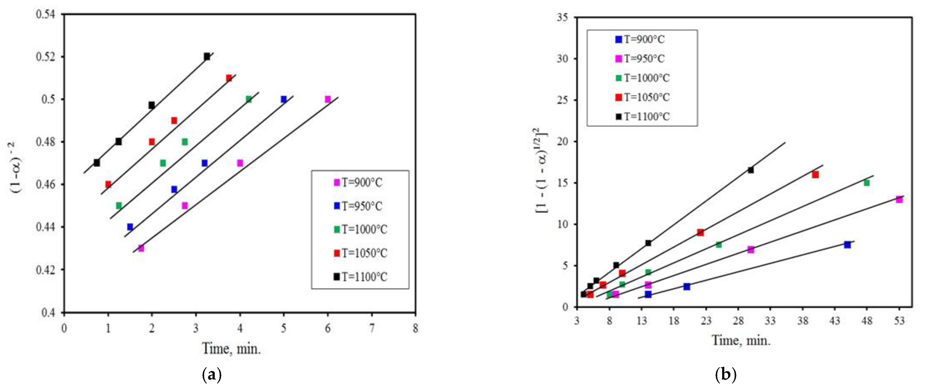
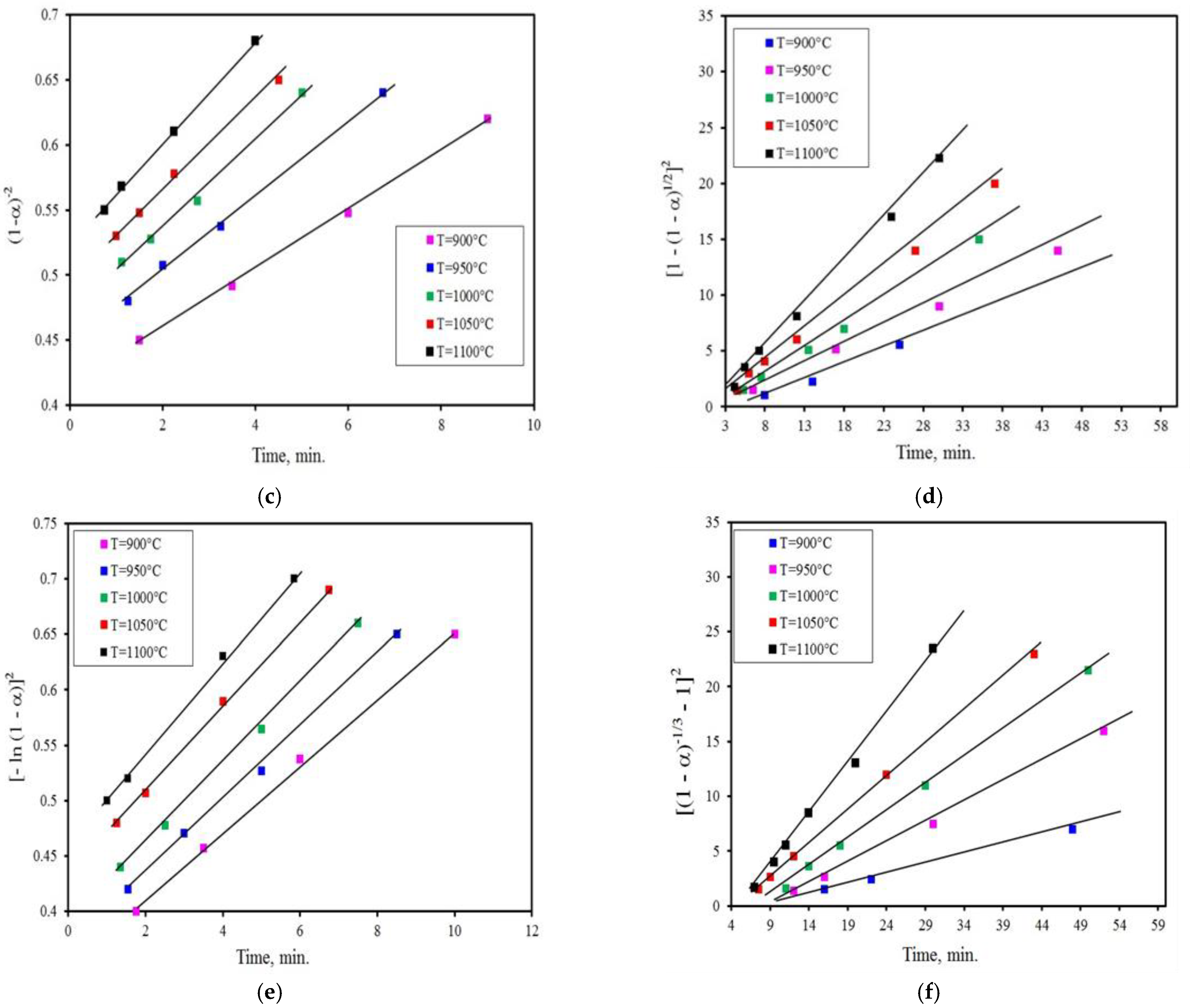
where G(α) denotes the integral expression of the mechanism function. Testing the linearity of G(α) against time can be used to establish the mechanism function. The slope represents the rate constant k(T), and the best-fitting equation is the most likely mechanism.
The rate-controlling mechanism of reduction can be predicted by the integral method. The chart of G(α) against time is shown in Figure 5. The reduction reaction, either by activated charcoal or charcoal, is characterized by two behaviors, as given in Figure 5. The first one is obtained up to conversion degree α ≤ 0.4 of the chemical reaction model, (n = 3) reaction order, namely (1−α)−2 provides the best statistical result (R = 0.99). This revealed that the chemical reaction is the regulating mechanism at this stage. The second stage is obtained up to the conversion degree of 0.4 < α ≤ 0.9 for the diffusion model, namely [1 − (1 − α)1/2]2 shows a liner pattern with R greater than 0.99 indicating that the gas diffusion regulates the reduction reaction. In the case of reduction with coal, the reduction is controlled by the Avrami–Erofeev Equation (m = ½) model [−ln (1 − α)2] at the initial stage. The rate-controlling mechanism is the 3-D diffusion model (Z-L-T), namely [(1−α)1/3−1]2 at the last stage. These findings were similar to those obtained by other researchers [1,6,35,37].

3.3. Determination of Activation Energy Values Ea

The Arrhenius equation (Equation (4)) was used to determine the activation energy values (Ea) for composite reduction processes.
k ( T ) = A exp ( E a R T )
where A represents the pre-exponential factor, Ea represents the apparent activation energy, R expresses the gas constant, and T refers to the absolute temperature.
Figure 6a–c depicts the Arrhenius plots in which the activation energy values (Ea) were calculated by graphing (lnk) vs. (1/T) at the early and final stages. Table 2 shows the obtained Ea values.
The lower Ea values computed for composite I and composite II compared to composite III are due to the larger surface area, higher fixed carbon, active sites, as well as higher porosity of activated charcoal and charcoal particles, which provide more opportunities for iron oxide reduction with carbon or carbon monoxide gas (direct and indirect reactions).
The morphological changes developed in reduced samples were evaluated under a scanning electron microscope (SEM). Figure 7 shows SEM images of composites I, II, and III reduced at 950 and 1050 °C, respectively. At 950 °C, Figure 7a–c depicts that the structure includes the creation of metallic iron whiskers, which decrease in number as the temperature increases. From Figure 7d–f, it can be seen that metallic iron grain growth occurs in a dense matrix structure, in which the number of whiskers greatly decreased. The structure formed becomes denser as the reduction temperature increases. This resulted from the metallic iron grains’ coalescence and connection with each other.
The various phases formed during the reduction of composite compacts were identified using X-ray diffraction. The XRD partial reduction patterns of the three different composites are shown in Figure 8. Hematite, magnetite, wustite, and metallic iron were clearly the predominant components in these samples. It was observed that the reduction of iron oxide pellet fines (Fe2O3) to metallic iron (Fe) occurs step by step (Fe2O3 → Fe3O4 → FeO → Fe), which was in agreement with the conclusions obtained by other researchers [20,40,41,42].

3.4. Measurements Based on (QMS) Analysis

The reduction mechanism was predicted by analyzing carbon monoxide and carbon dioxide in the output gas resulting from the reduction of iron oxide pellet fines/C composites. Figure 9a–c demonstrates the relationship between the gas composition CO and CO2 and the reduction time for composites I, II, and III at 1000 °C. The results show that the reduction of iron oxide pellet fines may be categorized into three successive reaction phases, which represent the reduction of Fe2O3 to Fe as follows:
i.
The reduction of Fe2O3 was accomplished in the first step by a direct interaction between Fe2O3 and carbon (3Fe2O3 + C = 2Fe3O4 + CO). As a result, CO gas was produced at the expense of nearby carbon particles. The CO gas generated in situ can also help in the reduction of hematite to magnetite (3Fe2O3 + CO = 2Fe3O4 + CO2). As a result, the amount of CO2 in the output gas increased.
ii.
In the second step, a portion of produced CO2 gas reacted with solid carbon to produce new and active CO gas (CO2 + C = 2CO). As a result, the CO concentration in the output gas increased. Depending on the gas concentration and the applied temperature, the produced CO gas could participate in the reduction of magnetite to wustite and part of FeO to metallic iron.
iii.
The unreduced FeO reacted with CO gas in the third step to form metallic iron (FeO + CO = Fe +CO2). The conversion of FeO to metallic iron took place at a rather modest pace. As a result, CO and CO2 concentrations in the output gas are comparatively low.

4. Conclusions

The current work was planned to study the reduction of fines rejected from iron pellets in DR plants with biomass carbon-bearing materials, namely activated charcoal and charcoal, which are isothermally reduced at 900–1100 °C in the presence of argon gas using TG and QMS techniques. The kinetic reduction results were compared with those of coal. The results obtained concluded the following:
  • The impact of a reducing agent on the reduction process is remarkable at relatively low temperatures.
  • The rate of reduction increased upon raising the temperature at the initial stage, and then progressively decreased during the final stages.
  • At the same temperature, the reduction rate and degree of reduction with activated charcoal and charcoal are higher than those with coal due to higher fixed carbon, surface area, and porosity.
  • The reduction reaction takes place step by step from hematite to metallic iron (Fe2O3 → Fe3O4 → FeO → Fe).
  • The reduction reaction, whether using activated charcoal or charcoal, has two different characteristics. The first one is obtained up to a conversion degree of α ≤ 0.4 and corresponds to the chemical reaction model (1−α)−2 indicating that the chemical reaction is the regulating mechanism at the first stage. At the latter stage, it occurs up to the conversion degree of 0.4 < α ≤ 0.9 for the gas diffusion model, namely [1 − (1 − α)1/2]2 is the rate-controlling mechanism. In the case of reduction with coal, the reduction reaction is regulated by the Avrame–Erofeev model [−ln(1 − α)2] in the early stage, whereas in the last stage, the rate-controlling mechanism is the 3-D diffusion model (Z-L-T), namely [(1 − α)−1/3 − 1]2.
  • The obtained activation energy values Ea for the reduction of composites I, II, and III at the initial stage are 62.39, 77.45, and 88.66 kJ/mole, respectively, while at the final stage, the computed Ea values are 172.29, 196.66, and 219.19 kJ/mole, respectively.
  • In QMS measurements, the examination of CO and CO2 concentrations reveals that the reduction process is significantly influenced by carbon gasification, which accelerates the rate of reduction.
  • The utilization of biomass carbon-bearing materials rather than fossil-origin resources is a vital option for the reduction of iron oxide pellet fines.

Author Contributions

Conceptualization, A.H. and Y.Y.; methodology, A.H., M.I.N. and M.H.E.-S.; software, A.H., Y.L., Y.X. and A.A.; validation, A.H., M.I.N., M.H.E.-S., and Y.Y.; formal analysis, A.H., M.H.E.-S. and M.O.; investigation, A.H., M.H.E.-S., M.O., M.I.N. and Y.Y.; resources, A.H., A.A., Y.L. and Y.X.; data curation, A.H., M.I.N. and M.H.E.-S. writing—original draft preparation, A.H.; writing—review and editing, Y.Y., M.O., A.H., M.I.N. and M.H.E.-S.; visualization; A.H., M.I.N., M.H.E.-S. and M.O. supervision; Y.Y.; project administration; Y.Y.; funding acquisition Y.Y. and M.O. All authors have read and agreed to the published version of the manuscript.

Funding

This research was funded by the Program for Professor of Special Appointment (Eastern Scholar) at Shanghai Institutions of Higher Learning (No. TP2015039), the National Natural Science Foundation of China (No. 51974182), the National 111 project, Grant/Award No. 17002, and CSC support for Ph.D. from the Belt and Road Countries.

Acknowledgments

We gratefully acknowledge the financial and scientific support from the Process Metallurgy Research Group, University of Oulu, Finland.

Conflicts of Interest

The authors declare no conflict of interest.

References

  1. Yuan, X.; Luo, F.; Liu, S.; Zhang, M.; Zhou, D. Comparative study on the kinetics of the isothermal reduction of iron ore composite pellets using coke, charcoal, and biomass as reducing agents. Metals 2021, 11, 340. [Google Scholar] [CrossRef]
  2. Gielen, D. Energy Technology Perspectives 2008: Scenarios and Strategies for CO2 Emissions Reduction. Int. J. Gas Turbine Propuls. Power Syst. 2010, 3, 1–9. [Google Scholar] [CrossRef]
  3. Ahmed, H. New trends in the application of carbon-bearing materials in blast furnace iron-making. Minerals 2018, 8, 561. [Google Scholar] [CrossRef] [Green Version]
  4. Suopajärvi, H.; Kemppainen, A.; Haapakangas, J.; Fabritius, T. Extensive review of the opportunities to use biomass-based fuels in iron and steelmaking processes. J. Clean. Prod. 2017, 148, 709–734. [Google Scholar] [CrossRef]
  5. Wang, X.; Lin, B. How to reduce CO2 emissions in China’s iron and steel industry. Renew. Sustain. Energy Rev. 2016, 57, 1496–1505. [Google Scholar] [CrossRef]
  6. Coleti, J.L.; Manfredi, G.V.P.; Vinhal, J.T.; Junca, E.; Espinosa, D.C.R.; Tenório, J.A.S. Kinetic investigation of self-reduction basic oxygen furnace dust briquettes using charcoals from different biomass. J. Mater. Res. Technol. 2020, 9, 13282–13293. [Google Scholar] [CrossRef]
  7. Xu, G.; Li, M.; Lu, P. Experimental investigation on flow properties of different biomass and torrefied biomass powders. Biomass-Bioenergy 2019, 122, 63–75. [Google Scholar] [CrossRef]
  8. Safarian, S.; Unnþórsson, R.; Richter, C. A review of biomass gasification modelling. Renew. Sustain. Energy Rev. 2019, 110, 378–391. [Google Scholar] [CrossRef]
  9. Zandi, M.; Martinez-Pacheco, M.; Fray, T.A. Biomass for iron ore sintering. Miner. Eng. 2010, 23, 1139–1145. [Google Scholar] [CrossRef]
  10. Lovel, R.; Vining, K.; Dell’Amico, M. Iron ore sintering with charcoal. Miner. Process. Extr. Metall. Rev. 2007, 116, 85–92. [Google Scholar] [CrossRef]
  11. Helle, H.; Helle, M.; Pettersson, F.; Saxén, H. Optimisation study of ironmaking using biomass. Ironmak. Steelmak. 2010, 37, 590–598. [Google Scholar] [CrossRef]
  12. Ueda, S.; Watanabe, K.; Yanagiya, K.; Inoue, R.; Ariyama, T. Improvement of reactivity of carbon iron ore composite with biomass char for blast furnace. ISIJ Int. 2009, 49, 1505–1512. [Google Scholar] [CrossRef] [Green Version]
  13. Luo, S.; Zhou, Y.; Yi, C. Two-step direct reduction of iron ore pellets by utilization of biomass: Effects of preheating temperature, pellet size and composition. J. Renew. Sustain. Energy 2013, 560, 441–446. [Google Scholar] [CrossRef]
  14. Luo, S.; Yi, C.; Zhou, Y. Direct reduction of mixed biomass—Fe2O3 briquettes using biomass-generated syngas. Renew. Energy 2011, 36, 3332–3336. [Google Scholar] [CrossRef]
  15. Barella, S.; Bondi, E.; Di Cecca, C.; Ciuffini, A.F.; Gruttadauria, A.; Mapelli, C.; Mombelli, D. New perspectivein steelmaking activity to increase competitiveness and reduce environmental impact. La Met. Ital. 2014, 16, 31–40. [Google Scholar]
  16. Sarkar, S.; Mazumder, D. Solid waste management in steel industry-challenges and opportunities. Eng. Technol. Int. J. Soc. Behav. Educ. Econ. Bus. Ind. Eng. 2015, 9, 978–981. [Google Scholar]
  17. Rieger, J.; Schenk, J.; Rieger, J.; Schenk, J. Residual processing in the European steel industry: A technological overview. J. Sustain. Met. 2019, 5, 295–309. [Google Scholar] [CrossRef]
  18. Branca, T.A.; Colla, V.; Algermissen, D.; Granbom, H.; Martini, U.; Morillon, A.; Pietruck, R.; Rosendahl, S. Reuse and recycling of by-products in the steel sector: Recent achievements paving the way to circular economy and industrial symbiosis in Europe. Metals 2020, 10, 345. [Google Scholar] [CrossRef] [Green Version]
  19. Ahmed, H.M.; Viswanathan, N.N.; Björkman, B. Isothermal reduction kinetics of self-reducing mixtures. Ironmak. Steelmak. 2016, 44, 66–75. [Google Scholar] [CrossRef]
  20. El-Geassy, A.A.; Halim, K.S.A.; Bahgat, M.; Mousa, E.A.; Shereafy, E.E.E.; El-Tawi, A.A. Carbothermic reduction of Fe2O3/C compacts: Comparative approach to kinetics and mechanism. Ironmak. Steelmak. 2013, 40, 534–544. [Google Scholar] [CrossRef]
  21. Chowdhury, G.M.; Roy, G.G.; Roy, S.K. Reduction kinetics of iron ore-graphite composite pellets in a packed-bed reactor under inert and reactive atmospheres. Metall. Mater. Trans. B 2008, 39, 160–178. [Google Scholar] [CrossRef]
  22. Ueda, S.; Yanagiya, K.; Watanabe, K.; Murakami, T.; Inoue, R.; Ariyama, T. Reaction model and reduction behavior of carbon iron ore composite in blast furnace. ISIJ Int. 2009, 49, 827–836. [Google Scholar] [CrossRef] [Green Version]
  23. Murakami, T.; Nishimura, T.; Kasai, E. Lowering reduction temperature of iron ore and carbon composite by using ores with high combined water content. ISIJ Int. 2009, 49, 1686–1693. [Google Scholar] [CrossRef] [Green Version]
  24. Matsui, Y.; Sawayama, M.; Kasai, A.; Yamagata, Y.; Noma, F. Reduction behavior of carbon composite iron ore hot briquette in shaft furnace and scope on blast furnace performance reinforcement. ISIJ Int. 2003, 43, 1904–1912. [Google Scholar] [CrossRef]
  25. Dutta, S.K.; Ghosh, A. A new method for measurement of degree of reduction in composite pellets of iron ore with carbonaceous matter. ISIJ Int. 1993, 33, 1104–1106. [Google Scholar] [CrossRef] [Green Version]
  26. Chu, M.; Nogami, H.; Yagi, J. Numerical analysis on charging carbon composite agglomerates into blast furnace. ISIJ Int. 2004, 44, 510–517. [Google Scholar] [CrossRef]
  27. Iguchi, Y.; Takada, Y. Rate of direct reactions measured in vacuum of iron ore-carbon composite pellets heated at high temperatures: Influence of carbonaceous materials, oxidation degree of iron oxides and temperature. ISIJ Int. 2004, 44, 673–681. [Google Scholar] [CrossRef]
  28. Narçin, N.; Aydln, S.; Şeşen, K.; Dikeç, F. Reduction of iron ore pellets with domestic lignite coal in a rotary tube furnace. Int. J. Miner. Process. 1995, 43, 49–59. [Google Scholar] [CrossRef]
  29. Jung, S. Effects of the Content and Particle Size of Char in the Composite on the Carbothermic Reduction of Titanomagnetite at 1100 °C. ISIJ Int. 2014, 54, 2933–2935. [Google Scholar] [CrossRef] [Green Version]
  30. Mishra, S.; Roy, G.G. Effect of Amount of Carbon on the Reduction Efficiency of Iron Ore-Coal Composite Pellets in Multi-layer Bed Rotary Hearth Furnace (RHF). Met. Mater. Trans. A 2016, 47, 2347–2356. [Google Scholar] [CrossRef] [Green Version]
  31. Sharma, T. Reduction of iron ore fines with coal fines. Ironmak. Steelmak. 1993, 20, 362–365. [Google Scholar]
  32. Kasai, E.; Kitajima, T.; Kawaguchi, T. Carbothermic reduction in the combustion bed packed with composite pellets of iron oxide and coal. ISIJ Int. 2000, 40, 842–849. [Google Scholar] [CrossRef] [Green Version]
  33. Yang, J.; Mori, T.; Kuwabara, M. Mechanism of Carbothermic Reduction of Hematite in Hematite–Carbon Composite Pellets. ISIJ Int. 2007, 47, 1394–1400. [Google Scholar] [CrossRef] [Green Version]
  34. Liu, G.; Strzov, V.; Lucas, J.A.; Wibberley, L.J. Thermal investigations of direct iron ore reduction with coal. Thermochem. Acta 2004, 410, 133. [Google Scholar] [CrossRef]
  35. Sun, Y.S.; Han, Y.X.; Gao, P.; Li, G.F. Investigation of kinetics of coal based reduction of oolitic iron ore. Ironmak. Steelmak. 2014, 41, 763–768. [Google Scholar] [CrossRef]
  36. Hammam, A.; Cao, Y.; El-Geassy, A.-H.; El-Sadek, M.; Li, Y.; Wei, H.; Omran, M.; Yu, Y. Non-Isothermal Reduction Kinetics of Iron Ore Fines with Carbon-Bearing Materials. Metals 2021, 11, 1137. [Google Scholar] [CrossRef]
  37. Sun, Y.; Han, Y.; Gao, P.; Wei, X.; Li, G. Thermogravimetric study of coal-based reduction of oolitic iron ore: Kinetics and mechanisms. Int. J. Miner. Processing 2015, 143, 87–97. [Google Scholar] [CrossRef]
  38. Tanaka, H. Thermal analysis and kinetics of solid state reactions. Thermochim. Acta 1995, 267, 29–44. [Google Scholar] [CrossRef]
  39. Vyazovkin, S.; Burnham, A.K.; Criado, J.M.; Pérez-Maqueda, L.A.; Popescu, C.; Sbirrazzuoli, N. ICTAC Kinetics Committee recommendations for performing kinetic computations on thermal analysis data. Thermochim. Acta 2011, 520, 1–19. [Google Scholar] [CrossRef]
  40. Park, H.; Sahajwalla, V. Effect of Alumina and Silica on the Reaction Kinetics of Carbon Composite Pellets at 1473 K. ISIJ Int. 2014, 54, 49–55. [Google Scholar] [CrossRef] [Green Version]
  41. Biswas, A.K. Principles of Blast Furnace Ironmaking; Cootha Publishing House: Brisbane, Australia, 1981. [Google Scholar]
  42. Fruehan, R.J. The rate of reduction of iron oxides by carbon. Met. Mater. Trans. A 1977, 8, 279–286. [Google Scholar] [CrossRef]
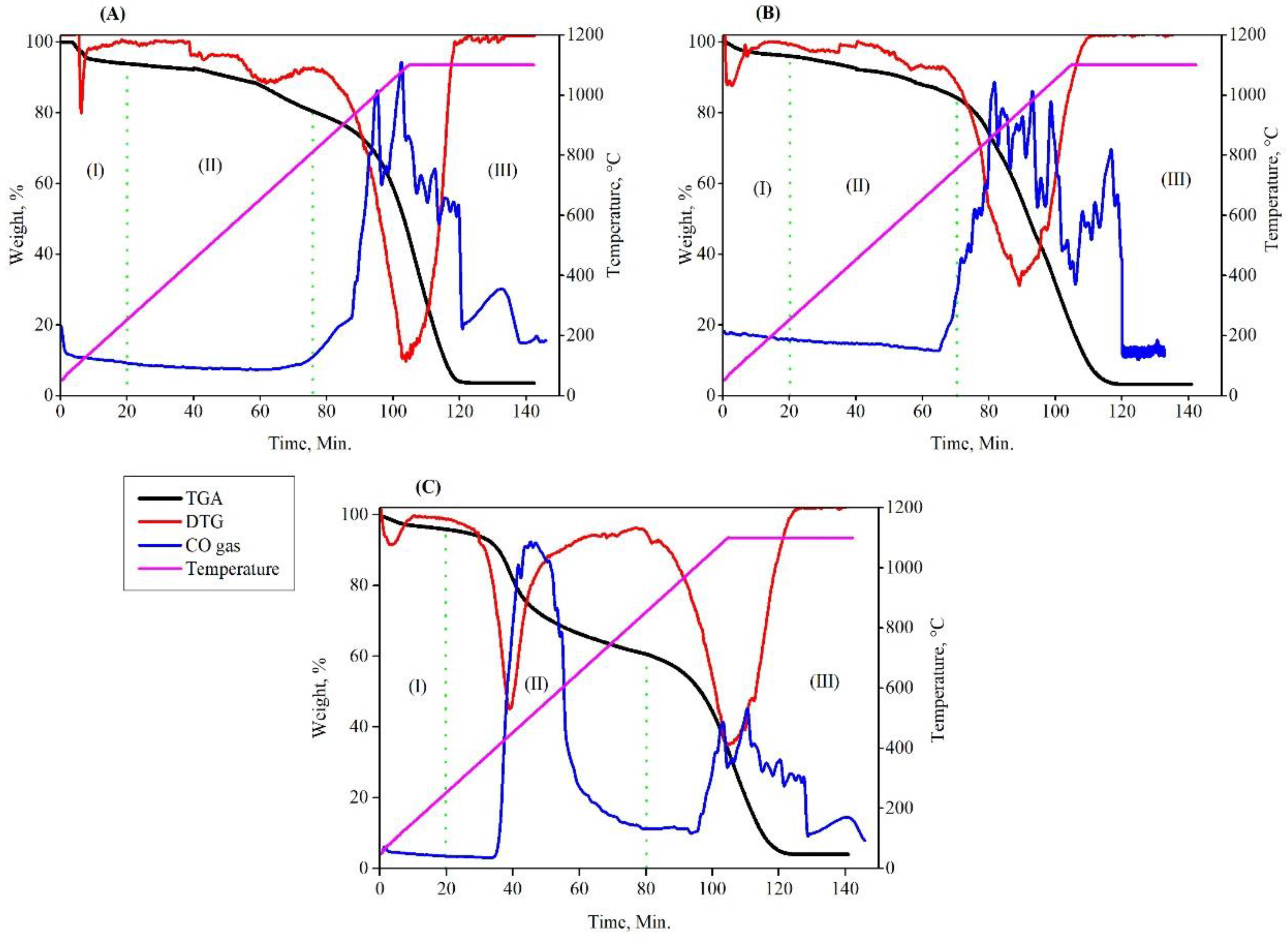
Figure 1. The gasification behavior of carbon-bearing materials being heated up to 1100 °C under CO2 atmosphere: (A) Charcoal, (B) activated charcoal, (C) coal.
Sustainability 14 08647 g001
Figure 2. Variation of cumulative pore volume and incremental volume with pore diameter for different composites.
Sustainability 14 08647 g002
Figure 3. Schematic diagram for the reduction system.
Sustainability 14 08647 g003
Figure 4. Effect of temperature on the total weight loss measured for (a) composite I, (b) composite II, (c) composite III.
Sustainability 14 08647 g004
Figure 5. Linear fitting of G(α) against time for composites I, II, and III in initial stage (a,c,e) and in final stage (b,d,f), respectively.
Sustainability 14 08647 g005aSustainability 14 08647 g005b
Figure 6. Arrhenius plots for the reduction of composites at initial and final stages: (a) Composite I, (b) composite II, (c) composite III.
Sustainability 14 08647 g006
Figure 7. SEM images of composites I, II, and III reduced at 950 °C (ac) and 1050 °C (df), respectively.
Sustainability 14 08647 g007
Figure 8. XRD patterns of partial reduction of iron oxide pellet fines composites at 1000 °C, (a) Composite I, (b) Composite II, (c) Composite III.
Sustainability 14 08647 g008aSustainability 14 08647 g008b
Figure 9. Variation of gas composition with reduction time for iron ore fines composites: (a) Composite I, (b) Composite II, (c) Composite III.
Sustainability 14 08647 g009
Table 1. Proximate analysis of carbon-bearing materials (wt.%).
Carbon SourceMoistureVolatilesAshFixed Carbon
Act. charcoal4.5122.581
Charcoal914374
Coal4.533.5458
Table 2. Computed Ea values for different composites.
Computed Ea (kJ/mol)At Initial StageAt Final Stage
Composite I62.39172.29
Composite II77.45196.48
Composite III88.66219.19
Publisher’s Note: MDPI stays neutral with regard to jurisdictional claims in published maps and institutional affiliations.